WO2013140834A1 - Dispositif de pliage, dispositif de posttraitement, et dispositif de formation d'images - Google Patents
Dispositif de pliage, dispositif de posttraitement, et dispositif de formation d'images Download PDFInfo
- Publication number
- WO2013140834A1 WO2013140834A1 PCT/JP2013/050590 JP2013050590W WO2013140834A1 WO 2013140834 A1 WO2013140834 A1 WO 2013140834A1 JP 2013050590 W JP2013050590 W JP 2013050590W WO 2013140834 A1 WO2013140834 A1 WO 2013140834A1
- Authority
- WO
- WIPO (PCT)
- Prior art keywords
- unit
- rotational
- rotation
- folding
- rotation drive
- Prior art date
- Legal status (The legal status is an assumption and is not a legal conclusion. Google has not performed a legal analysis and makes no representation as to the accuracy of the status listed.)
- Ceased
Links
Images


Classifications
-
- B—PERFORMING OPERATIONS; TRANSPORTING
- B65—CONVEYING; PACKING; STORING; HANDLING THIN OR FILAMENTARY MATERIAL
- B65H—HANDLING THIN OR FILAMENTARY MATERIAL, e.g. SHEETS, WEBS, CABLES
- B65H45/00—Folding thin material
- B65H45/02—Folding limp material without application of pressure to define or form crease lines
- B65H45/04—Folding sheets
-
- B—PERFORMING OPERATIONS; TRANSPORTING
- B65—CONVEYING; PACKING; STORING; HANDLING THIN OR FILAMENTARY MATERIAL
- B65H—HANDLING THIN OR FILAMENTARY MATERIAL, e.g. SHEETS, WEBS, CABLES
- B65H45/00—Folding thin material
- B65H45/12—Folding articles or webs with application of pressure to define or form crease lines
- B65H45/18—Oscillating or reciprocating blade folders
-
- B—PERFORMING OPERATIONS; TRANSPORTING
- B65—CONVEYING; PACKING; STORING; HANDLING THIN OR FILAMENTARY MATERIAL
- B65H—HANDLING THIN OR FILAMENTARY MATERIAL, e.g. SHEETS, WEBS, CABLES
- B65H37/00—Article or web delivery apparatus incorporating devices for performing specified auxiliary operations
- B65H37/06—Article or web delivery apparatus incorporating devices for performing specified auxiliary operations for folding
-
- B—PERFORMING OPERATIONS; TRANSPORTING
- B65—CONVEYING; PACKING; STORING; HANDLING THIN OR FILAMENTARY MATERIAL
- B65H—HANDLING THIN OR FILAMENTARY MATERIAL, e.g. SHEETS, WEBS, CABLES
- B65H43/00—Use of control, checking, or safety devices, e.g. automatic devices comprising an element for sensing a variable
-
- B—PERFORMING OPERATIONS; TRANSPORTING
- B65—CONVEYING; PACKING; STORING; HANDLING THIN OR FILAMENTARY MATERIAL
- B65H—HANDLING THIN OR FILAMENTARY MATERIAL, e.g. SHEETS, WEBS, CABLES
- B65H2403/00—Power transmission; Driving means
- B65H2403/50—Driving mechanisms
- B65H2403/51—Cam mechanisms
- B65H2403/512—Cam mechanisms involving radial plate cam
-
- B—PERFORMING OPERATIONS; TRANSPORTING
- B65—CONVEYING; PACKING; STORING; HANDLING THIN OR FILAMENTARY MATERIAL
- B65H—HANDLING THIN OR FILAMENTARY MATERIAL, e.g. SHEETS, WEBS, CABLES
- B65H2801/00—Application field
- B65H2801/24—Post -processing devices
- B65H2801/27—Devices located downstream of office-type machines
Definitions
- the present invention relates to a folding apparatus capable of folding a sheet member such as a sheet-like image forming material, a post-processing apparatus, and an image forming apparatus including the post-processing apparatus.
- post-processing apparatuses that can be connected to the image forming apparatus main body such as a copier or a multifunction peripheral.
- the post-processing device performs predetermined post-processing on the sheet (or a bundle of sheets) carried out from the image forming apparatus main body.
- Post-processing includes, for example, punching processing (punch processing) for sheets, stapling processing for sheet bundles, and processing for sheets (sheet bundles).
- the post-processing device having a folding processing function has a blade and a roller pair.
- the blade is bent in contact with the sheet (a bundle of sheets).
- the roller pair accepts the folded sheet (sheet bundle) so as to be sandwiched together with the blade, and makes a crease.
- a load may be applied to the blade and the blade may be damaged.
- Patent Document an image forming apparatus having a clutch unit that allows a roller pair to be driven and rotated in a state where a blade and a sheet (a bundle of sheets) are inserted between rollers.
- the blade may be damaged.
- the post-processing device stops the processing operation with the blade inserted between the rollers.
- the work load for returning from this state to the normal state is very large.
- the present invention includes a conveyance path, a placement unit, a penetrating unit, a first folding member, a second folding member, a drive mechanism, a rotational position detection mechanism, a signal receiving unit, a rotational drive control unit,
- the present invention relates to a folding device.
- the conveyance path is configured to be able to convey the sheet member in a predetermined conveyance direction.
- the placement section constitutes a part of the transport path and has a placement surface on which the sheet member can be placed.
- the penetrating portion is formed in the mounting portion, and is formed to penetrate from the mounting surface side to an opposite surface opposite to the mounting surface.
- the first folding member is disposed on the opposite surface side of the placement portion, an initial position where the tip portion is located at a predetermined position on the opposite surface side, and the tip portion is inserted through the penetrating portion.
- a first folding member that is movably disposed to a projecting position located at a predetermined position on the surface side, and moves from the initial position to the projecting position in a state where the sheet member is disposed on the mounting portion. Thus, the sheet member is moved while being bent.
- the second folding member is disposed on the placement surface side of the placement unit, and the first folding member is moved together with the folded sheet member in a state where the first folding member is located at the protruding position. Accept as if pinched.
- the drive mechanism includes a rotation drive unit capable of outputting a rotation drive force and a rotation member rotated by the rotation drive force from the rotation drive unit, and the first folding member is moved to the initial position and the protruding position. And reciprocate.
- the rotation position detection mechanism detects a rotation position of the rotation member and outputs rotation position information.
- the signal receiving unit receives a predetermined signal.
- the rotational drive control unit receives the rotational position information from the rotational position detection mechanism.
- the driving mechanism can output a rotational driving force.
- the drive mechanism includes a changing unit that changes the rotary motion of the rotary member to a reciprocating motion.
- the rotation drive unit can switch the direction of rotation drive.
- the rotating member is directly or indirectly connected to the rotation driving unit.
- the rotation drive control unit When the signal receiving unit receives the predetermined signal, the rotation drive control unit is in a state where the first folding member is moving from the initial position toward the protruding position based on the rotation position information. Alternatively, it is determined whether the first folding member is moving from the protruding position toward the initial position. The rotational drive control unit, when determining that the first folding member is moving from the initial position toward the protruding position, the rotational drive to switch the rotational drive direction to a reverse rotational direction. When the first folding member is determined to be moving from the protruding position toward the initial position, the rotational driving unit is controlled so as to maintain the rotational driving direction as it is.
- the present invention includes a conveyance path, a placement unit, a penetrating unit, a first folding member, a second folding member, a drive mechanism, a rotational position detection mechanism, a rotational load monitoring unit, and a rotational drive control unit. And a folding device.
- the conveyance path is configured to be able to convey the sheet member in a predetermined conveyance direction.
- the placement section constitutes a part of the transport path and has a placement surface on which the sheet member can be placed.
- the penetrating portion is formed in the mounting portion, and is formed to penetrate from the mounting surface side to an opposite surface opposite to the mounting surface.
- the first folding member is disposed on the opposite surface side of the placement portion, an initial position where the tip portion is located at a predetermined position on the opposite surface side, and the tip portion is inserted through the penetrating portion.
- a first folding member that is movably disposed to a projecting position located at a predetermined position on the surface side, and moves from the initial position to the projecting position in a state where the sheet member is disposed on the mounting portion. Thus, the sheet member is moved while being bent.
- the second folding member is disposed on the placement surface side of the placement unit, and the first folding member is moved together with the folded sheet member in a state where the first folding member is located at the protruding position. Accept as if pinched.
- the drive mechanism includes a rotation drive unit capable of outputting a rotation drive force and a rotation member rotated by the rotation drive force from the rotation drive unit, and the first folding member is moved to the initial position and the protruding position. And reciprocate.
- the rotation position detection mechanism detects a rotation position of the rotation member and outputs rotation position information.
- the rotation load monitoring unit detects a rotation load generated in the rotation driving unit and determines whether the rotation load is equal to or greater than a predetermined value.
- the rotational drive control unit receives the rotational position information from the rotational position detection mechanism.
- the driving mechanism can output a rotational driving force.
- the drive mechanism includes a changing unit that changes the rotary motion of the rotary member to a reciprocating motion.
- the rotation drive unit can switch the direction of rotation drive.
- the rotating member is directly or indirectly connected to the rotation driving unit.
- the rotational drive control unit moves the first folding member from the initial position toward the protruding position based on the rotational position information. Whether the first folding member is moving from the protruding position toward the initial position.
- the rotational drive control unit when determining that the first folding member is moving from the initial position toward the protruding position, the rotational drive to switch the rotational drive direction to a reverse rotational direction.
- the rotational driving unit is controlled so as to maintain the rotational driving direction as it is.
- FIG. 5 is a flowchart illustrating an operation in a folding processing unit in the copier according to the first embodiment. It is a figure explaining the state where the braid
- FIG. 10 is a flowchart illustrating an operation in a folding processing unit in the copier according to the second embodiment. It is a figure explaining the crank mechanism which comprises the folding process part in other embodiment. It is a figure explaining operation
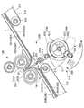
- FIG. 1 is a diagram for explaining the overall configuration of the copier according to the first embodiment.
- the copier 1 includes a copier main body 2 (image forming apparatus main body) and a post-processing apparatus 100.
- the copier main body 2 image forming apparatus main body
- the post-processing apparatus 100 is disposed on the paper discharge side of the copier body 2.
- the post-processing device 100 performs punching processing, stapling processing, and half-folding processing on a paper (image forming material, sheet member) T on which a toner image is formed.
- the copying machine main body 2 includes a document transport unit 10, a document reading unit 20, a first paper transport unit 30, a toner image forming unit 40, a transfer unit 50, and a fixing unit 60.
- the document transport unit 10 is an ADF (Auto Document Feeder), and includes a document placement unit 11, a first feed roller 12, a guide 13, a timing roller pair 14, and a document discharge unit 15.
- the first feed roller 12 supplies the document G placed on the document placement unit 11 to the timing roller pair 14 one by one in order.
- the timing roller pair 14 matches the timing at which the document reading unit 20 reads the document G with the timing at which the document G is supplied to the position where the document G is read by the document reading unit 20 (the position where the guide 13 is disposed). Then, the document G is transported or the transport of the document G is stopped.
- the guide 13 guides the conveyed document G to a first reading surface 21a described later.
- the document discharge unit 15 discharges the document G read by the document reading unit 20 (passed through the guide 13) to the outside of the copier body 2.
- a document stacking unit 16 is formed outside the copying machine main body 2 in the document discharge unit 15. In the document stacking unit 16, the documents G discharged from the document discharge unit 15 are stacked and stacked.
- the document reading unit 20 includes a first reading surface 21a and a second reading surface 22a.
- the first reading surface 21 a is formed along the upper surface of the first contact glass 21.
- the first contact glass 21 is disposed to face the guide 13.
- the first reading surface 21a is a surface for reading the document G.
- the second reading surface 22a is disposed adjacent to the first reading surface 21a.
- the second reading surface 22a extends over most of the right side of the first reading surface 21a in the case shown in FIG.
- the second reading surface 22 a is used when reading the document G without using the document transport unit 10.
- the second reading surface 22 a is formed along the upper surface of the second contact glass 22.
- a document G is placed on the second contact glass 22.
- the second reading surface 22a is a surface for reading the document G.
- the document reading unit 20 includes an illumination unit 23, a first mirror 24, a second mirror 25, a third mirror 26, an imaging lens 27, and an imaging unit 28.
- the illumination unit 23, the first mirror 24, the second mirror 25, the third mirror 26, the imaging lens 27, and the imaging unit 28 are disposed inside the copier body 2.
- the illumination unit 23 and the first mirror 24 move in the sub-scanning direction X, respectively.
- the second mirror 25 and the third mirror 26 are arranged on the left side of the illumination unit 23 and the first mirror 24 in FIG. Further, the second mirror 25 and the third mirror 26 each move in the sub-scanning direction X while keeping the distance (optical path length) from the first reading surface 21a or the second reading surface 22a to the imaging unit 28 constant.
- the distance (optical path length) from the first reading surface 21 a or the second reading surface 22 a to the imaging unit 28 is via the first mirror 24, the second mirror 25, the third mirror 26, and the imaging lens 27. Distance.
- the illumination unit 23 is a light source that irradiates the original G with light.
- the first mirror 24, the second mirror 25, and the third mirror 26 are mirrors for guiding the light reflected by the document G to the imaging lens 27 while keeping the optical path length constant.
- the imaging lens 27 focuses the light incident from the third mirror 26 on the imaging unit 28.
- the imaging unit 28 includes a plurality of imaging elements.
- the plurality of image sensors are arranged along the main scanning direction (a direction orthogonal to the sub-scanning direction X).
- the imaging element is an element for obtaining image data based on a formed optical image by converting incident light into an electrical signal, and is, for example, a charge coupled device (CCD).
- CCD charge coupled device
- the first paper transport unit 30 includes a second feed roller 31, a third feed roller 32, a registration roller pair 33, a switching unit 39, a first paper discharge unit 34, and a second paper discharge unit 38.
- the second feed roller 31 supplies the paper T stored in the paper feed cassette 36 to the transfer unit 50.
- the third feed roller 32 supplies the paper T placed on the manual feed tray 37 to the transfer unit 50.
- the registration roller pair 33 transports the paper T or stops the transport of the paper T in order to match the timing at which the toner image is formed on the transfer unit 50 and the timing at which the paper T is supplied to the transfer unit 50. .
- the registration roller pair 33 corrects skew (oblique paper feeding) of the paper T.
- the switching unit 39 switches the transport direction of the paper T so that the paper T carried out from the fixing unit 60 is transported to one of the first paper discharge unit 34 and the second paper discharge unit 38.
- the first paper discharge unit 34 and the second paper discharge unit 38 discharge the paper T on which the toner image is fixed to the outside of the copier body 2.
- a paper discharge stacking unit 35 is formed outside the copier body 2 in the first paper discharge unit 34. In the paper discharge stacking unit 35, the sheets T discharged from the first paper discharge unit 34 are stacked and stacked.
- the toner image forming unit 40 includes a photosensitive drum 41, a charging unit 42, a laser scanner unit 43, a developing device 44, a cleaning unit 45, a toner cartridge 46, a primary transfer roller 47, and an intermediate transfer belt 48. And a counter roller 49.
- the photoconductor drum 41 (41a, 41b, 41c, 41d) functions as a photoconductor or an image carrier in order to form toner images of black, cyan, magenta, and yellow, respectively.
- the charging unit 42, the laser scanner unit 43, and the developing unit 44 are sequentially arranged from the upstream side to the downstream side along the rotation direction of the photosensitive drum 41.
- a cleaning unit 45 is disposed.
- the charging unit 42 charges the surface of the photosensitive drum 41.
- the laser scanner unit 43 is arranged away from the surface of the photosensitive drum 41.
- the laser scanner unit 43 scans and exposes the surface of the photosensitive drum 41 based on the image data relating to the original G read by the original reading unit 20. As a result, the exposed portion of the charge is removed from the surface of the photosensitive drum 41 to form an electrostatic latent image.
- the developing unit 44 attaches toner to the electrostatic latent image formed on the surface of the photosensitive drum 41 to form a toner image.
- the cleaning unit 45 removes toner and the like remaining on the surface of the photosensitive drum 41 after being neutralized after the surface of the photosensitive drum 41 is neutralized by a static eliminator (not shown).
- the toner cartridge 46 stores toner of each color supplied to the developing device 44.
- the toner cartridge 46 and the developing device 44 are connected by a toner supply path (not shown).
- the primary transfer rollers 47 (47a, 47b, 47c, 47d) are arranged on the opposite sides of the intermediate transfer belt 48 from the photosensitive drums 41a, 41b, 41c, 41d, respectively.
- the intermediate transfer belt 48 is a belt that passes through the toner image forming unit 40 and the transfer unit 50. A part of the intermediate transfer belt 48 is sandwiched between the photosensitive drums 41a, 41b, 41c, and 41d and the primary transfer rollers 47a, 47b, 47c, and 47d. A toner image formed on the surface of each of the photosensitive drums 41a, 41b, 41c, and 41d is primarily transferred onto a part of the intermediate transfer belt 48.
- the opposing roller 49 is disposed inside the annular intermediate transfer belt 48.
- the facing roller 49 is a driving roller for causing the intermediate transfer belt 48 to advance in the direction of arrow A shown in FIG.
- the transfer unit 50 includes a secondary transfer roller 51.
- the secondary transfer roller 51 is disposed on the opposite side of the intermediate transfer belt 48 from the facing roller 49.
- the secondary transfer roller 51 sandwiches a part of the intermediate transfer belt 48 with the opposing roller 49. Further, the secondary transfer roller 51 secondarily transfers the toner image primarily transferred to the intermediate transfer belt 48 onto the paper T.
- the fixing unit 60 includes a heating rotator 61 and a pressure rotator 62.
- the heating rotator 61 and the pressure rotator 62 sandwich the paper T on which the toner image is secondarily transferred, melt and pressurize the toner, and fix the toner to the paper T.
- the post-processing apparatus 100 is configured to be connectable to the copier body 2.
- the post-processing apparatus 100 includes a second paper transport unit 110 (transport path), a punching unit 120, a stapling unit 130, and a folding processing unit 190.
- the second paper transport unit 110 includes a transport path 110a, a transport path 110b, a transport path 110c, a transport path 110d, and a transport path 110e.
- the second paper transport unit 110 is configured to transport the sheet-shaped paper T in a predetermined transport direction.
- the conveyance path 110 a includes a carry-in unit 111, a branch guide 112, and a first discharge unit 113.
- the carry-in unit 111 carries the paper T discharged from the second paper discharge unit 38 of the copier body 2 into the post-processing apparatus 100.
- the carry-in unit 111 conveys the paper T carried into the post-processing apparatus 100 to the punching unit 120.
- the branch guide 112 switches the conveyance direction of the paper T discharged from the punching unit 120 to one of the first discharge unit 113 and the stapling unit 130.
- the first discharge unit 113 discharges the paper T discharged from the punching unit 120 and the paper T discharged from the stapling unit 130 from the post-processing device 100.
- a main tray 114 is disposed outside the post-processing apparatus 100 in the first discharge unit 113.
- the sheets T discharged from the first discharge unit 113 are stacked and accumulated on the main tray 114.
- the punching unit 120 performs a series of processes related to the punching process.
- the punching process is a process of forming holes used for binding the paper T at predetermined positions on the paper.
- the stapling unit 130 binds the paper T with staples (stapling needles) and stops (staple processing).
- the staple unit 130 includes a paper tray 131, a receiving unit 132, a staple processing unit 133, and a conveyance roller 134.
- the paper tray 131, the receiving portion 132, and the transport roller 134 constitute a part of the transport path 110c.
- the paper tray 131 temporarily stores a plurality of papers T that are carried from the punching unit 120 by switching the branch guide 112.
- the receiving part 132 receives and holds the lower end part of the paper T carried into the paper receiving base 131.
- the staple processing unit 133 moves to the vicinity of the end portion or the central portion of the paper T temporarily stored in the paper receiving tray 131, and performs the stapling process near the end portion or the central portion of the paper T. Do.
- the transport roller 134 transports a bundle of sheets that have been stapled (saddle-stitched) near the center of the sheet T from the sheet receiving base 131 to the folding processing unit 190.
- the folding processing unit 190 for example, folds a bundle of sheets that are saddle-stitched from the vicinity of the center (folding process).
- the folding processing unit 190 will be described in detail below.
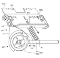
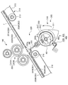
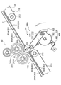
- FIG. 2 is a diagram for explaining the configuration of the folding processing unit constituting the post-processing apparatus.
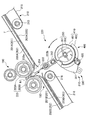
- FIG. 3A is a diagram illustrating a cam mechanism that constitutes a folding processing unit.
- FIG. 3B is a diagram illustrating a cam mechanism that constitutes the folding processing unit.
- paper T includes a bundle of paper T.
- the folding processing unit 190 is disposed on the downstream side of the second paper transport unit 110.
- a single sheet T or a bundle of sheets T on which the stapling process has been performed is introduced into the folding processing unit 190.
- the folding processing unit 190 performs a folding process on the introduced paper T.
- the folding processing unit 190 discharges the paper T on which the folding processing has been performed to the lower discharge tray 145.
- the lower discharge tray 145 is provided at the lower part of one side surface of the post-processing apparatus 100.
- the folding processing unit 190 includes a sheet carry-in path 200, a sheet placement member 201 (a placement portion) having a sheet placement surface 202 (a placement surface), a penetrating portion 204, an alignment portion 210, and an extrusion member 211.
- the receiving member 212, the folding part 220, and the second discharge part 230 are provided.
- the sheet carry-in path 200 is a carry-in path for carrying the paper T that has been conveyed through the conveyance path into the folding processing unit 190. As shown in FIG. 1, the sheet carry-in path 200 is disposed on the upper right side of the folding processing unit 190. The sheet carry-in path 200 conveys the paper T toward the sheet placement member 201 (sheet placement surface 202).
- the sheet placing member 201 constitutes a part of the conveyance path 110d (second paper conveyance unit 110).
- the sheet placement member 201 has a sheet placement surface 202 on which a sheet-like paper T can be placed.
- the sheet placing member 201 includes an upstream sheet placing member 201A, a downstream sheet placing member 201B, and a penetrating portion 204.
- the upstream sheet placement member 201A has an upstream sheet placement surface 202A.
- the downstream sheet placing member 201B has a downstream sheet placing surface 202B.
- the upstream sheet placing member 201 ⁇ / b> A and the downstream sheet placing member 201 ⁇ / b> B are members for placing the paper T in order to perform a folding process on the carried paper T.
- the upstream sheet placement member 201 ⁇ / b> A and the downstream sheet placement member 201 ⁇ / b> B are disposed so as to extend from the upper right side to the lower left side inside the folding processing unit 190.
- the upstream sheet placing member 201A and the downstream sheet placing member 201B are arranged with a through-hole 204 described later interposed therebetween.
- the upstream sheet placing member 201A and the downstream sheet placing member 201B are configured by plate-like members.
- the upstream sheet placing member 201A and the downstream sheet placing member 201B are arranged so as to be in a straight line in the sheet conveyance direction.
- the paper T placed on the upstream sheet placement member 201A and the downstream sheet placement member 201B is sent to the first nip N1 of the folding roller pair 223 by a blade member 222 (described later) inserted through the penetration portion 204. .
- the penetrating portion 204 is formed to penetrate from the sheet placement surface 202 side to the opposite surface 203 side opposite to the sheet placement surface 202.
- the penetrating portion 204 is disposed between the upstream sheet placing member 201A and the downstream sheet placing member 201B.
- the through portion 204 is a through hole through which the blade member 222 is inserted.
- the aligning unit 210 is provided to align the positions of the sheets T on the upstream sheet placing member 201A and the downstream sheet placing member 201B so that the folded sheet T can be accurately folded.
- the alignment unit 210 performs alignment of the paper T in a direction parallel to the transport direction of the paper T (downward direction in FIG. 1) and a direction orthogonal to the transport direction of the paper T.
- the pushing member 211 and the receiving member 212 are provided to align the front end and the rear end of the paper T in the transport direction of the paper T.
- the push-out member 211 is disposed on the upstream side in the sheet conveyance direction.
- the receiving member 212 is disposed on the downstream side in the sheet conveyance direction.
- the extruded member 211 is formed so that the cross section is substantially L-shaped.
- a drive pulley 213 and a driven pulley 214 are disposed below the upstream sheet placement member 201A.
- An endless belt 215 is stretched around the driving pulley 213 and the driven pulley 214.
- the pushing member 211 is attached to the endless belt 215. Further, the push-out member 211 protrudes from the upper part of the upstream sheet placement member 201A at a substantially central position in the width direction of the upstream sheet placement member 201A.
- the driving pulley 213 is disposed at a position corresponding to the substantially central portion in the sheet conveying direction in the upstream sheet placing member 201A.
- the driven pulley 214 is disposed in the vicinity of the upstream end of the upstream sheet placing member 201A. Further, a rotational driving force from a motor (not shown) is transmitted to the driving pulley 213 by a driving mechanism (not shown).
- the driving pulley 213 and the driven pulley 214 can freely rotate in the forward and reverse directions.
- the driven pulley 214 is driven and rotated via the endless belt 215.
- the pushing member 211 protrudes from the upper portion of the upstream sheet placing member 201A and moves in a direction parallel to the sheet conveying direction.
- the receiving member 212 is formed so that the cross section is substantially L-shaped.
- a driving pulley 216 and a driven pulley 217 are disposed below the downstream sheet placing member 201B.
- An endless belt 218 is stretched around the driving pulley 216 and the driven pulley 217.
- the receiving member 212 is attached to the endless belt 218. Further, the receiving member 212 protrudes from the upper part of the downstream sheet placing member 201B at a substantially central position in the width direction of the downstream sheet placing member 201B.
- the driving pulley 216 is disposed in the vicinity of the upstream end of the downstream sheet placing member 201B.
- the driven pulley 217 is disposed in the vicinity of the downstream end of the downstream sheet placing member 201B. Further, a rotational driving force from a motor (not shown) is transmitted to the driving pulley 216 by a driving mechanism (not shown).
- the driving pulley 216 and the driven pulley 217 can freely rotate in the forward and reverse directions.
- the driven pulley 217 is driven and rotated via the endless belt 218.
- the receiving member 212 protrudes from the upper part of the downstream sheet placing member 201B and moves in the direction parallel to the sheet conveying direction over the entire length of the downstream sheet placing member 201B.
- the upstream side sheet placement member 201A and the downstream side sheet placement member 201B By moving the push-out member 211 and the receiving member 212 in accordance with the size of the paper T (the length in the transport direction), the upstream side sheet placement member 201A and the downstream side sheet placement member 201B The position is aligned in a direction parallel to the sheet conveyance direction, that is, in the length direction of the paper T.
- the width adjusting member (not shown) is a member for aligning the paper T in the direction orthogonal to the transport direction of the paper T, that is, in the width direction of the paper T.
- a pair of width adjusting members is provided in a direction parallel to the transport direction of the paper T.
- the pair of width adjusting members are disposed on the upstream sheet placing member 201 ⁇ / b> A and the downstream sheet placing member 201 ⁇ / b> B at an interval in the width direction with the blade member 222 sandwiched in the sheet conveying direction.
- the width alignment of the paper T and the skew correction are performed by the pair of width alignment members.
- the pair of width adjusting members is provided on the upper side of the upstream sheet placing member 201A.
- the pair of width adjusting members has a rack and pinion mechanism (not shown). This rack and pinion mechanism is connected to and driven by a motor (not shown) that can freely rotate in the forward and reverse directions.
- the width adjusting unit is moved in accordance with the size (length in the width direction) of the paper T carried into the upper part of the upstream sheet mounting member 201A and the downstream sheet mounting member 201B. . Thereby, matching such as width adjustment of the paper T and correction of skew is performed.
- the folding unit 220 forms a crease in the paper T at a first nip N1 (described later). In addition, the folding unit 220 sends out the paper T on which the crease is formed toward the second discharge unit 230.
- the folding unit 220 includes a blade member 222 (first folding member) and a folding roller pair 223 (second folding member). Further, the folding unit 220 includes a drive mechanism 300 and a rotational position detection mechanism 400.
- the blade member 222 is a member for contacting the paper T and performing a folding process on the paper T.
- the blade member 222 has a leading end 222 a that abuts against the paper T.
- the end of the blade member 222 opposite to the tip end 222a is held by the holding member 222b.
- the blade member 222 is disposed on the surface 203 side opposite to the sheet placement surface 202 of the sheet placement member 201.
- the blade member 222 is movably disposed at an initial position HP (see FIG. 6) and a protruding position TP (see FIG. 8).
- the initial position HP see FIG. 6
- the tip end portion 222a of the blade member 222 is located at a predetermined position on the opposite surface 203 side.
- the tip end portion 222a of the blade member 222 is positioned at a predetermined position on the sheet placement surface 202 side through the penetrating portion 204.
- the blade member 222 moves while bending the paper T by moving from the initial position HP to the protruding position TP in a state where the paper T is disposed on the sheet placing member 201. Specifically, the blade member 222 abuts on the paper T so as to push out the paper T, and feeds the paper T into a first nip N1 (described later) while being bent (folded).
- the blade member 222 moves along a direction substantially orthogonal to the sheet placement surface 202 including the sheet conveyance direction and the sheet width direction.
- the folding roller pair 223 is disposed on the sheet placement surface 202 side of the sheet placement member 201.
- the folding roller pair 223 is disposed above the blade member 222 in the present embodiment.
- the folding roller pair 223 includes a first roller 223A and a second roller 223B. Both the first roller 223A and the second roller 223B constituting the folding roller pair 223 are rotationally driven via a rotation driving mechanism (not shown).
- a first nip N1 is formed between the first roller 223A and the second roller 223B.
- the folding roller pair 223 receives the folded sheet T and the blade member 222 in a state where the blade member 222 is located at the protruding position TP.
- the drive mechanism 300 is a drive mechanism that causes the blade member 222 to reciprocate between the initial position HP and the protruding position TP.
- the drive mechanism 300 includes a rotation drive unit 360 (see FIG. 4), a rotation member 350 (see FIG. 2), and a cam mechanism 310 (change unit).
- the rotation driving unit 360 can output a rotation driving force.
- the rotation drive unit 360 is configured to be able to switch the direction of rotation drive.
- the rotation driving unit 360 includes a motor and the like.
- the rotation driving unit 360 is configured to be able to switch the rotation direction between a normal rotation direction that is a normal rotation direction and a reverse rotation direction that is a rotation direction opposite to the normal rotation direction.
- the rotation drive unit 360 is controlled by a rotation drive control unit 370 (see FIG. 4A described later). For example, the rotation drive unit 360 determines that the rotation drive control unit 370 (drive control unit) receives a predetermined signal and the blade member 222 is moving from the initial position HP toward the protruding position TP. In this case, the rotation drive control unit 370 is controlled to switch the rotation drive direction to the reverse rotation direction. Further, in the rotation drive unit 360, the rotation drive control unit 370 (drive control unit) receives a predetermined signal and the blade member 222 is moving from the protruding position TP toward the initial position HP. If it is determined, the rotation drive control unit 370 controls to maintain the direction of rotation drive as it is.
- a rotation drive control unit 370 see FIG. 4A described later. For example, the rotation drive unit 360 determines that the rotation drive control unit 370 (drive control unit) receives a predetermined signal and the blade member 222 is moving from the initial position HP toward the protruding position TP. In this case, the
- the predetermined signal is, for example, a signal output when a jam detection unit (not shown) detects a paper jam or an overload from a monitoring unit (not shown) that monitors the load in the rotation drive unit 360. This is a signal or the like output when it is detected.
- the rotation drive unit 360 detects that the blade member 222 is positioned at the initial position HP based on rotation position information received from the rotation position detection mechanism 400 (described later) by the rotation drive control unit 370, the rotation drive unit 360 rotates.
- the drive control unit 370 is controlled to stop the rotational drive.
- the rotating member 350 is directly or indirectly connected to the rotation driving unit 360.
- the rotating member 350 includes a shaft member 351 and a rotating plate member 352 connected to one end of the shaft member 351.
- the rotating member 350 is rotated by the rotation driving force from the rotation driving unit 360. That is, the shaft member 351 is rotated by the rotational driving force from the rotational driving unit 360. Then, the rotating plate member 352 is rotated by the rotation driving force from the rotation driving unit 360 via the shaft member 351.
- the cam mechanism 310 is a drive mechanism that changes the rotary motion of the rotary member 350 to a reciprocating motion.
- the cam mechanism 310 changes the rotational motion to the reciprocating motion so that the blade member 222 reciprocates once when the rotating member 350 makes one revolution.
- the cam mechanism 310 includes a cam member 311, a contact member 312, and a spring member 380.
- the cam member 311 is connected to the shaft member 351 in the rotating member 350.
- the cam member 311 rotates integrally with the rotating member 350.
- the abutting member 312 is formed on the holding member 222b.
- the holding member 222b holds the blade member 222.
- the contact member 312 is disposed so as to contact the outer edge of the cam member 311.
- the contact member 312 is configured to reciprocate as the cam member 311 rotates.
- the blade member 222 is held by the holding member 222b where the contact member 312 is formed. Therefore, when the contact member 312 reciprocates, the blade member 222 also reciprocates.
- One end 381 of the spring member 380 is connected to the shaft member 351.
- the other end 383 of the spring member 380 is connected to the holding member 222b.
- the spring member 380 urges the contact member 312 toward the cam member 311 via the shaft member 351 and the holding member 222b.
- the spring member 380 maintains the state in which the contact member 312 is in contact with the outer edge of the cam member 311.
- the rotation position detection mechanism 400 detects the rotation position of the rotation member 350.
- the rotational position detection mechanism 400 outputs rotational position information.
- the rotational position detection mechanism 400 includes a detected part 410 and a detection sensor 420.
- the detected portion 410 is disposed on the outer edge of the rotating plate member 352 constituting the rotating member 350.
- the detected part 410 has a first region 401 (transmission region) and a second region 402 (non-transmission region).
- the first region 401 is a region located at a measurement position of the detection sensor 420 described later in a state where the blade member 222 is located between the initial position HP and immediately before the protruding position TP.
- the first region 401 is a region through which light output from the detection sensor 420 is transmitted.
- the second region 402 is a region located at a position to be measured by a detection sensor 420 described later in a state where the blade member 222 is located between the protruding position TP and immediately before the initial position HP.
- the second region 402 is a region that does not transmit light output from the detection sensor 420 (non-transmissive region, light shielding region).
- the aspect of the to-be-detected part 410 is not limited to the above-mentioned.
- the detection sensor 420 is disposed at a position corresponding to the detected part 410.
- the detection sensor 420 detects detection information (position information) regarding the detected part 410.
- the detection sensor 420 outputs detected detection information (position information). In other words, the detection sensor 420 detects the rotation position of the rotation member 350 (rotation plate member 352) and outputs rotation position information (position information).
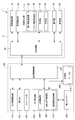
- FIG. 4A is a block diagram illustrating a functional configuration of the copier (post-processing apparatus) according to the first embodiment.
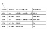
- FIG. 4B is a diagram illustrating a table stored in the storage unit.
- the copying machine main body 2 includes the above-described components (the document conveying unit 10, the document reading unit 20, the first sheet conveying unit 30, the toner image forming unit 40, the transfer unit 50, and the fixing unit 60).
- the image forming unit 3 includes a first paper transport unit 30, a toner image forming unit 40, a transfer unit 50, and a fixing unit 60.
- the description about the component mentioned above is abbreviate
- the copying machine main body 2 includes an operation unit 70, a storage unit 80, and a main control unit 90 in addition to the functional configuration described above.
- the operation unit 70 includes a numeric keypad (not shown), a touch panel (not shown), a start key (not shown), and the like.
- the numeric keypad is operated to input numbers such as the number of copies to be printed.
- the touch panel displays a plurality of keys to which various functions are assigned. As an example of various functions, there are a print magnification setting function, a function of allocating a plurality of pages to one sheet of paper T (such as 2 in 1), and a function of executing punching processing, stapling processing, or half-folding processing.
- the keys displayed on the touch panel are operated (touched) to cause the copier 1 to execute any of various functions.
- the start key is operated to execute printing. When any key is operated, the operation unit 70 supplies a signal indicating that the key is operated to the main control unit 90.
- the storage unit 80 includes a hard disk, a semiconductor memory, and the like.
- the storage unit 80 stores image data based on the document G read by the document reading unit 20.
- the storage unit 80 stores a control program used in the copier 1, data used by the control program, and the like.
- the main control unit 90 controls the document conveying unit 10, the document reading unit 20, the image forming unit 3, the touch panel that constitutes the operation unit 70, and the post-processing control unit 150.
- the post-processing apparatus 100 includes the above-described components (the second paper transport unit 110, the punching unit 120, the stapling unit 130, and the folding processing unit 190). In addition, the description about the component mentioned above is abbreviate
- the folding processing unit 190 includes a rotation drive unit 360, a signal reception unit 365, and a rotation drive control unit 370.
- the rotation drive unit 360 is as described above.
- the signal receiving unit 365 receives a predetermined signal. In addition, when receiving a predetermined signal, the signal receiving unit 365 notifies the rotation drive control unit 370 that the signal has been received.
- the signal is detected when an overload is detected from, for example, a signal output when a jam detection unit (not shown) detects a paper jam or a monitoring unit that monitors the load in the rotation drive unit 360. Signal etc. output in the case.
- the rotation drive control unit 370 controls the rotation drive unit 360.
- the rotational drive control unit 370 receives rotational position information from the rotational position detection mechanism 400 (detection sensor 420). Further, the rotation drive control unit 370 receives the notification from the signal receiving unit 365.
- the rotation drive control unit 370 is configured such that the blade member 222 protrudes from the initial position HP based on the received rotation position information. It is determined whether the blade member 222 is moving toward the TP or the blade member 222 is moving from the protruding position TP toward the initial position HP.
- the rotational drive control unit 370 determines that the blade member 222 is moving from the initial position HPk toward the protruding position TP, the rotational drive unit switches the rotational drive direction to the reverse rotational direction. 360 is controlled. Further, when it is determined that the blade member 222 is moving from the protruding position TP toward the initial position HP, the rotation drive control unit 370 controls the rotation drive unit 360 so as to maintain the direction of rotation drive as it is. To do. In addition, after performing the above-described control, the rotational drive control unit 370 causes the rotational drive unit 360 to stop the rotational drive when detecting that the blade member 222 is positioned at the initial position P based on the rotational position information. Control.
- the rotational drive control unit 370 is in a state where the blade member 222 is moving from the initial position HP toward the protruding position TP based on the received rotational position information, or the blade member 222 is It is determined whether or not the projecting position TP is moving toward the initial position HP.
- the rotation drive control unit 370 refers to a table 610 stored in the storage unit 600 described later, and makes the above determination based on the received rotation position information.
- the table 610 stored in the storage unit 600 stores the (current) rotation state, the detection state, the blade state (position), and the drive control content in association with each other.
- the rotational drive control unit 370 receives rotational position information including information of “no detection” from the detection sensor 420, the blade member 222 moves from the initial position HP toward the protruding position TP. It is determined that it is in a state. Then, the rotational drive control unit 370 controls the rotational drive unit 360 so as to switch the rotational drive direction to the reverse rotational direction.
- the rotational drive control unit 370 when the rotational drive control unit 370 receives rotational position information including “detected” information from the detection sensor 420, the blade member 222 moves from the protruding position TP toward the initial position HP. It is determined that it is in a state. Then, the rotational drive control unit 370 controls the rotational drive unit 360 so as to maintain the rotational drive direction as it is.
- the rotation drive control unit 370 switches the information received from the detection sensor 420 from “with detection” to “without detection” when the rotation direction in the rotation drive unit 360 is normal rotation. When this is detected, it is detected that the blade member 222 is located at the initial position HP. Then, the rotation drive control unit 370 controls the rotation drive unit 360 to stop the rotation drive. Further, after the above-described control, the rotation drive control unit 370 switches the information received from the detection sensor 420 from “no detection” to “detection” when the rotation direction in the rotation drive unit 360 is reverse rotation. When this is detected, it is detected that the blade member 222 has slightly passed the initial position P.
- the rotation drive control unit 370 controls the rotation drive unit 360 to stop the rotation drive.
- the initial position HP is set not inside the end portion of the first region 401 but inside the end portion of the first region 401 will be described.
- the rotation drive control unit 370 confirms that the information received from the detection sensor 420 is switched from “detected” to “not detected” when the rotation direction in the rotation drive unit 360 is normal rotation.
- the rotation drive unit 360 is controlled to stop the rotation drive after further performing a predetermined amount of forward rotation.
- the rotation drive control unit 370 switches the information received from the detection sensor 420 from “no detection” to “detection” when the rotation direction in the rotation drive unit 360 is reverse rotation.
- the rotational drive unit 360 is controlled so as to stop the reverse rotational drive and to rotate forward by a predetermined amount.
- the main control unit 90 detects that the start key is operated by receiving a signal indicating that the start key constituting the operation unit 70 has been operated.
- the main control unit 90 drives the first feed roller 12 of the document transport unit 10 to supply the document G to the first reading surface 21a.
- the main control unit 90 causes the document reading unit 20 to generate image data based on the document G supplied to the first reading surface 21a.
- the main control unit 90 temporarily stores the image data generated by the document reading unit 20 in the storage unit 80.
- the main control unit 90 forms a toner image on the paper T based on the image data temporarily stored in the storage unit 80.
- the main controller 90 controls the first paper transport unit 30, the toner image forming unit 40, the transfer unit 50, and the fixing unit 60 that constitute the image forming unit 3. That is, the main control unit 90 drives the second feed roller 31 or the third feed roller 32 to transport the paper T to the transfer unit 50. Further, the main control unit 90 supplies the image data generated for each color to the laser scanner unit 43 based on the image data.
- the main control unit 90 forms an electrostatic latent image on the photosensitive drum 41 by the laser light emitted from the laser scanner unit 43.
- the main controller 90 causes the developing device 44 to form a toner image on the photosensitive drum 41.
- the main control unit 90 primarily transfers the toner image formed on the photosensitive drum 41 to the intermediate transfer belt 48.
- the main controller 90 causes the secondary transfer roller 51 to secondarily transfer the toner image primarily transferred to the intermediate transfer belt 48 to the paper T.
- the main control unit 90 controls the heating rotator 61 to be heated to a predetermined temperature.
- the main control unit 90 causes the heating rotator 61 to melt the toner of the toner image secondarily transferred to the paper T.
- the main controller 90 fixes the toner onto the paper T by the pressure rotator 62 pressed against the heating rotator 61. Further, the main control unit 90 causes the first paper transport unit 30 to discharge the paper T on which the toner image is fixed from the second paper discharge unit 38.
- the main control unit 90 controls the post-processing control unit 150 to perform post-processing on the paper T discharged from the second paper discharge unit 38.
- the post-processing control unit 150 causes the paper T discharged from the second paper discharge unit 38 to be carried into the post-processing device 100 by the second paper transport unit 110. Then, the post-processing control unit 150 stops the transport of the paper T by the second paper transport unit 110 at the punching unit 120.
- the post-processing control unit 150 lowers the punching processing unit (not shown) of the punching unit 120 toward the paper T. Then, the post-processing control unit 150 forms perforations in the paper T.
- the post-processing control unit 150 causes the second paper transport unit 110 to transport the paper T on which the perforations are formed.
- the post-processing control unit 150 causes the first paper discharge unit 113 to discharge the paper T transported by the second paper transport unit 110.
- the post-processing control unit 150 switches the transport direction of the paper T carried into the post-processing apparatus 100 to a direction orthogonal to the transport direction of the paper T by the branch guide 112. Thereby, the post-processing control unit 150 temporarily stores the paper T in the paper receiving tray 131.
- the post-processing control unit 150 moves the staple processing unit 133 when a predetermined number of sheets T are temporarily stored in the sheet receiving tray 131. Then, the post-processing control unit 150 causes the staple processing unit 133 to perform stapling processing in the vicinity of the end portion or the central portion of the paper T.
- the post-processing control unit 150 causes the first discharge unit 113 to discharge the bundle of paper on which the staple processing has been performed.
- the post-processing control unit 150 converts the bundle of the saddle-stitched paper into the folding processing unit 190 (sheet placing member). 201).
- the rotation drive control unit 370 moves the blade member 222 toward the bundle of sheets (sheet T) placed on the sheet placement member 201 (sheet placement surface 202). 360 is controlled. Thereby, the blade member 222 moves the bundle of sheets toward the folding roller pair 223 while folding. The blade member 222 pushes the folded sheet bundle into the first nip N1. Then, the post-processing control unit 150 folds the bundle of sheets by the folding roller pair 223. Further, the post-processing control unit 150 controls various driving units (not shown) so as to convey the folded sheet bundle toward the second discharge unit 230.
- FIG. 5 is a flowchart for explaining the operation of the folding processing unit in the copier according to the first embodiment.
- FIG. 6 is a diagram illustrating a state where the blade is located at the initial position.
- FIG. 7 is a diagram illustrating a state where the blade is moving from the initial position to the protruding position.
- FIG. 8 is a diagram illustrating a state where the blade is located at the protruding position.
- FIG. 9 is a diagram illustrating a state in which the blade has moved from the protruding position to the initial position side.
- FIG. 6 is a diagram illustrating a state where the blade is located at the initial position.
- FIG. 7 is a diagram illustrating a state where the blade is moving from the initial position to the protruding position.
- FIG. 8 is a diagram illustrating a state where the blade is located at the protruding position.
- FIG. 9 is a diagram illustrating a state in which the blade has moved from the protruding position to the
- FIG. 10 is a diagram illustrating a state where the blade has returned to the initial position.
- FIG. 11 is a diagram for explaining a state in which the blade is further moved from the position of FIG. 7 to the protruding position side.
- FIG. 12 is a diagram illustrating a state in which the blade has moved further from the position of FIG. 8 to the initial position side.
- the paper T is carried into the folding processing unit 190 through the conveyance path 110d.
- the paper T carried into the folding processing section 190 is placed on the upstream sheet placement surface 202A of the upstream sheet placement member 201A and the downstream sheet placement surface 202B of the downstream sheet placement member 201B.
- the alignment unit 210 aligns the position of the paper T.
- the blade member 222 stands by in a state where it is located at the initial position HP. Specifically, the blade member 222 is below (on the opposite surface 203 side) the upstream sheet placement surface 202A of the upstream sheet placement member 201A and the downstream sheet placement surface 202B of the downstream sheet placement member 201B. Waiting to be located.
- the rotation drive control unit 370 controls the rotation drive unit 360 to rotate in the normal rotation direction.
- the rotating member 350 rotates forward and the cam member 311 connected to the rotating member 350 rotates forward.
- the tip end portion 222 a of the blade member 222 moves through the contact member 312, passes through the through portion 204, and moves toward the sheet placement surface 202.
- the blade member 222 moves from the initial position HP toward the protruding position TP. Accordingly, the blade member 222 abuts on the paper T and moves the paper T toward the folding roller pair 223 side while bending the paper T.
- the rotation drive control unit 370 controls the rotation drive unit 360 so as to continuously rotate in the normal rotation direction.
- the rotating member 350 further rotates forward
- the cam member 311 connected to the rotating member 350 further rotates forward.
- the tip end portion 222a of the blade member 222 further moves via the contact member 312 and moves (positions) to the protruding position TP. Accordingly, the blade member 222 pushes the folded paper T into the first nip N1 formed by the folding roller pair 223.
- the rotation drive control unit 370 controls the rotation drive unit 360 so as to continuously rotate in the normal rotation direction.
- the rotating member 350 further rotates forward
- the cam member 311 connected to the rotating member 350 further rotates forward.
- the tip end portion 222a of the blade member 222 is directed from the protruding position TP toward the initial position HP. Moving.
- the blade member 222 is separated from the folded paper T.
- the rotation drive control unit 370 controls the rotation drive unit 360 so as to continuously rotate in the normal rotation direction.
- the rotating member 350 further rotates forward, and the cam member 311 coupled to the rotating member 350 further rotates forward.
- the tip end portion 222a of the blade member 222 further moves toward the initial position HP (position) To do).
- the rotation drive control unit 370 detects that the blade member 222 is located at the initial position HP based on the position information from the detection sensor 420, the rotation drive control unit 370 controls the rotation drive unit 360 to stop the rotation drive.
- the pair of folding rollers 223 receives the paper T pushed by the blade member 222 and sends it out to the conveyance path 110e while making a crease in the paper T. Further, the sheet T that has been subjected to the folding process is discharged from the second discharge unit 230. Then, the post-processing device 100 (folding processing unit 190) stops the folding process (operation).
- step ST11 the rotation drive control unit 370 confirms whether a notification indicating that a predetermined signal has been received from the signal reception unit 365 has been received.
- step ST11, NO the rotation drive control unit 370 returns the process to before step ST11. If the rotation drive control unit 370 has received the notification (step ST11, YES), the process proceeds to step ST12.
- step ST12 the rotational drive control unit 370 determines whether or not the blade member 222 is moving from the initial position HP toward the protruding position TP based on the rotational position information received from the detection sensor 320. judge. For example, as illustrated in FIG. 11, the rotational drive control unit 370 determines that the blade member 222 is moving from the initial position HP toward the protruding position TP (YES in step ST12). Proceed to step ST13. For example, as illustrated in FIG. 12, the rotational drive control unit 370 determines that the blade member 222 is not in a state of moving from the initial position HP toward the protruding position TP (the blade member 222 is moved from the protruding position TP. When it is determined that the vehicle is moving toward the initial position HP (NO in step ST12), the process proceeds to step ST14.
- the rotation drive control unit 370 controls the rotation drive unit 360 to drive in the reverse rotation whose rotation direction is reverse (switch to the reverse rotation direction).
- the blade member 222 moves from the position shown in FIG. 11 to the initial position HP shown in FIG. 6 via the position shown in FIG.
- the blade member 222 returns to the initial position HP without being positioned at the protruding position TP on which more load is applied.
- the blade member 222 can return to the initial position HP with a low load.
- step ST14 the rotation drive control unit 370 controls the rotation drive unit 360 so as to maintain the normal rotation.
- the blade member 222 moves from the position shown in FIG. 12 to the initial position HP shown in FIG. 10 via the position shown in FIG.
- the blade member 222 has already exceeded the protruding position TP where more load is applied. Therefore, the blade member 222 can return to the initial position HP in a state where the load is low, when the rotation driving unit 360 is driven while being rotated in the forward direction.
- step ST15 the rotational drive control unit 370 confirms whether the blade member 222 is in the initial position HP based on the rotational position information. If the rotation drive control unit 370 does not confirm that the blade member 222 is positioned at the initial position HP (step ST15, NO), the process returns to step ST15. Further, when it is confirmed that the blade member 222 is located at the initial position HP (step ST15, YES), the rotation drive control unit 370 controls the rotation drive unit 360 to stop driving. Then, the post-processing device 100 (folding processing unit 190) stops the folding process (operation).
- the first embodiment it is possible to provide a post-processing apparatus that can suppress the breakage of the folding member and reduce the work burden on the operator when a failure occurs.
- an image forming apparatus including the post-processing apparatus can be provided.
- the post-processing device 100 (the copying machine 1) is a drive mechanism that reciprocates the blade member 222 between the initial position HP and the protruding position TP, and can output a rotational driving force.
- a rotation drive unit 360 capable of switching the direction of the rotation drive, a rotation member 350 connected directly or indirectly to the rotation drive unit 360 and rotated by a rotation drive force from the rotation drive unit 360, and a rotation member 350, a drive mechanism having a cam mechanism 310 that changes the rotational motion of the rotating member 350 to a reciprocating motion, and a rotational position detecting mechanism 400 that detects the rotational position of the rotating member 350 and outputs rotational position information.
- a signal receiving unit 365 that receives a predetermined signal, and a rotational drive control unit 370 that receives rotational position information from the rotational position detection mechanism 400, the signal receiving unit 365.
- the blade member 222 is moving from the initial position HP toward the protruding position TP based on the rotational position information, or the blade member 222 is moved from the protruding position TP toward the initial position HP. If the blade member 222 is determined to be moving from the initial position HP toward the protruding position TP, the rotational drive direction is switched to the reverse rotation direction.
- the rotation that controls the rotation drive unit 360 to maintain the rotation drive direction as it is.
- a drive control unit 370 As a result, the post-processing apparatus 100 (the copying machine 1) can return the blade member 222 to the initial position HP with a small load. Thereby, the post-processing apparatus 100 (the copy machine 1) can suppress (further) damage to the blade member 222. Further, the post-processing apparatus 100 (the copy machine 1) can suppress the work burden on the user.
- the rotational position detection mechanism 400 includes the detected part 410 arranged on the rotating member 350, and positional information about the detected part 410 that is arranged at a position corresponding to the detected part 410 ( Detection sensor 420 for detecting position information).
- the post-processing apparatus 100 can determine the position of the blade member 222 based on the detection information.
- the post-processing apparatus 100 is configured to be able to determine the position of the blade member 222 with a simple configuration.
- the cam mechanism 310 changes the rotational motion to the reciprocating motion so that the blade member reciprocates once when the rotating member 350 makes one revolution. Accordingly, the post-processing apparatus 100 (the copy machine 1) can accurately determine the position of the blade member 222 and the movement state of the blade member 222 by acquiring the rotational position information on the rotating member 350.
- the rotational drive control unit 370 detects that the blade member 222 is located at the initial position HP based on the rotational position information
- the rotational drive unit 360 stops the rotational drive.
- the post-processing device 100 the copying machine 1
- the post-processing apparatus 100 the copy machine 1 can suppress the work burden on the user.
- FIG. 13 is a block diagram illustrating a functional configuration of the copier (post-processing apparatus) according to the second embodiment.
- FIG. 14 is a flowchart for explaining the operation of the folding processing unit in the copier according to the second embodiment.
- the second embodiment will be described mainly with respect to differences from the first embodiment. For the points not specifically described in the second embodiment, the description of the first embodiment is appropriately applied or incorporated.
- the second embodiment of the present invention is mainly different from the first embodiment in that a rotation load monitoring unit 366 is provided instead of the signal receiving unit 365 in the first embodiment.
- the rotation driving unit 360 can output a rotation driving force.
- the rotation drive unit 360 is configured to be able to switch the direction of rotation drive.
- the rotation driving unit 360 includes a motor and the like.
- the rotation drive unit 360 is configured to be able to switch the rotation direction between a normal rotation direction that is a normal rotation direction and a reverse rotation direction that is a rotation direction opposite to the normal rotation direction.
- a motor etc. which comprise the rotation drive part 360
- various motors such as a stepping motor, a motor with a brush, a brushless motor, can be used, for example.
- a detection method according to the characteristics of each motor can be adopted as a detection method of the rotation load in the rotation load monitoring unit 366 described later.
- the rotation load monitoring unit 366 will be described later.
- the rotation drive unit 360 is controlled by a rotation drive control unit 370 (see FIG. 13 described later), as in the first embodiment.
- the rotational drive unit 360 determines that the rotational load in the rotational drive unit 360 is greater than or equal to a predetermined value by a rotational load monitoring unit 366 described later, and the rotational drive control unit 370 (drive control)
- the rotational drive control unit 370 controls the rotational drive direction to be switched to the reverse rotational direction.
- the rotational drive unit 360 determines that the rotational load in the rotational drive unit 360 is greater than or equal to a predetermined value by a rotational load monitoring unit 366 described later, and the blade member 222 protrudes by the rotational drive control unit 370 (drive control unit).
- the rotation drive control unit 370 controls the rotation drive direction to be maintained as it is.
- the folding processing unit 190 includes a rotation drive unit 360, a rotation load monitoring unit 366, and a rotation drive control unit 370.
- the rotation drive unit 360 is the same as that in the first embodiment.
- the rotational load monitoring unit 366 detects the rotational load in the rotational drive unit 360 and determines whether the rotational load is greater than or equal to a predetermined value. When the rotational load monitoring unit 366 determines that the rotational load in the rotational drive unit 360 is greater than or equal to a predetermined value, the rotational load monitoring unit 366 notifies the rotational drive control unit 370 to that effect.
- the rotational load monitoring unit 366 can detect the rotational load based on a predetermined parameter. For example, the rotation load monitoring unit 366 detects the rotation load using the current value, rotation speed, rotation cycle, counter electromotive force, and the like as parameters.
- the rotational load monitoring unit 366 determines that the rotational load in the rotation driving unit 360 has exceeded a predetermined value when the current value has changed a predetermined value, for example, when the current value has exceeded a predetermined value.
- the rotational load monitoring unit 366 may include, for example, a resistance element mounted on a substrate (not shown) and a current detection unit.
- the rotation driving unit 360 when the rotation driving unit 360 is a stepping motor, a brushed motor, a brushless motor, or the like, the rotation speed of the rotation driving unit 360 (motor) can be used as a parameter. Then, the rotation load monitoring unit 366 determines that the rotation load in the rotation driving unit 360 has become equal to or greater than a predetermined value when the rotation speed has changed by a predetermined value, for example, when the rotation speed has become equal to or less than the predetermined speed. In this case, the rotational load monitoring unit 366 calculates, for example, a rotational speed based on a plurality of through holes formed at predetermined intervals in the detected unit 410 and detection results from the detection sensor 320. And may be configured.
- the rotation load monitoring unit 265 determines that the rotation load in the rotation driving unit 360 is greater than or equal to a predetermined value when the rotation cycle changes a predetermined value, for example, when the rotation frequency is equal to or greater than a predetermined value.
- the rotation load monitoring unit 366 includes, for example, a rotation cycle calculation unit that calculates a rotation cycle based on one or a plurality of through holes formed in the detection unit 410 and a detection result from the detection sensor 320. It may be configured.
- the rotation driving unit 360 is configured to include a brushless motor
- the rotation load monitoring unit 366 calculates the rotation period based on the Hall element disposed on the substrate and the signal output from the Hall element. And a period calculation unit.
- the rotation drive control unit 370 controls the rotation drive unit 360.
- the rotational drive control unit 370 receives rotational position information from the rotational position detection mechanism 400 (detection sensor 420).
- the rotation drive control unit 370 receives the notification from the rotation load monitoring unit 366.
- the rotational drive control unit 370 detects the rotational load in the rotational drive unit 360 by the rotational load monitoring unit 366 and determines that the rotational load is greater than or equal to a predetermined value (rotational load monitoring unit). 366), the blade member 222 is moving from the initial position HP toward the protruding position TP based on the received rotational position information, or the blade member 222 is initially moved from the protruding position TP. It is determined whether the vehicle is moving toward the position HP.
- step ST21 control flow, see FIG. 14
- step ST11 control flow, see FIG. 5
- step ST ⁇ b> 21 the rotational drive control unit 370 confirms whether a notification that the rotational load has become equal to or greater than a predetermined value has been received from the rotational load monitoring unit 366. If the rotation drive control unit 370 has not received the notification (step ST21, NO), the process returns to step ST21. If the rotation drive control unit 370 has received the notification (step ST21, YES), the process proceeds to step ST22.
- step ST22 to step ST25 in the second embodiment Since the operation from step ST22 to step ST25 in the second embodiment is the same as the operation from step ST12 to step ST15 in the first embodiment, the description of the first embodiment is referred to and the description in the second embodiment is made. Is omitted.
- the post-processing device 100 is a drive mechanism that reciprocates the blade member 222 between the initial position HP and the protruding position TP, and can output a rotational driving force.
- a rotation drive unit 360 capable of switching the direction of rotation drive; a rotation member 350 that is directly or indirectly connected to the rotation drive unit 360 and rotated by a rotation drive force from the rotation drive unit 360;
- the rotational load monitoring unit 366 that detects the rotational load generated in the drive unit 360 and determines whether the rotational load is equal to or greater than a predetermined value, and the rotational position detection mechanism 400.
- the rotational drive control unit 370 receives the rotational position information and the rotational load monitoring unit 366 determines that the rotational load is greater than or equal to a predetermined value, the blade member 222 protrudes from the initial position HP based on the rotational position information. It is determined whether the blade member 222 is moving toward the position TP or the blade member 222 is moving from the protruding position TP toward the initial position HP, and the blade member 222 is moved from the initial position HP to the protruding position TP. When it is determined that the rotation is moving, the rotation drive unit is controlled to switch the rotation drive direction to the opposite rotation direction, and the blade member 222 moves from the protruding position TP toward the initial position HP.
- the post-processing device 100 (copy machine 1) can return the blade member 222 to the initial position HP with a low load, as in the first embodiment.
- the post-processing apparatus 100 (the copy machine 1) can suppress (further) damage to the blade member 222.
- the post-processing device 100 (the copy machine 1) can reduce the work load on the user.
- the rotational position detection mechanism 400 includes the detected part 410 arranged on the rotating member 350 and detection information related to the detected part 410 arranged at a position corresponding to the detected part 410. And a detection sensor 420 for detection.
- the post-processing device 100 (copy machine 1) can determine the position of the blade member 222 based on the detection information, as in the first embodiment. Accordingly, the post-processing apparatus 100 (the copying machine 1) is configured to be able to determine the position of the blade member 222 with a simple configuration.
- the preferred embodiment of the post-processing apparatus 100 (copy machine 1) according to the present invention has been described above, but the post-processing apparatus 100 (copy machine 1) according to the present invention is not limited to the above-described embodiment. It can be implemented in various forms.
- the drive mechanism is configured to include a cam mechanism as the changing unit, but is not limited thereto.
- the drive mechanism may have a crank mechanism, for example.
- the crank mechanism 310A will be described with reference to FIGS. 15A to 15D.
- FIG. 15A is a diagram illustrating a crank mechanism that constitutes a folding processing unit according to another embodiment.
- FIG. 15B is a diagram for explaining the operation of the crank mechanism.
- FIG. 15C is a diagram illustrating the operation of the crank mechanism.
- FIG. 15D is a diagram illustrating the operation of the crank mechanism.
- the drive mechanism 300A includes a crank mechanism 370.
- the crank mechanism 370 is a drive mechanism that changes the rotational motion of the crank portion 371 to reciprocating motion via the rod portion 372.
- the crank mechanism 370 changes the rotational motion to a reciprocating motion so that the blade member 222 reciprocates once when the crank portion 371 rotates once.
- the crank mechanism 370 includes a crank part 371 and a rod part 372.
- the crank part 371 is rotationally driven by the driving force from the rotational drive part 360.
- One end of the rod portion 372 is connected to a predetermined position on the outer peripheral side of the crank portion 371.
- the rod portion 372 changes the rotational motion in the crank portion 371 to reciprocating motion.
- a blade member 222 is attached to the other end of the rod portion 372.
- the crank mechanism 370 reciprocates the blade member 222 in the same manner as the cam mechanism 310 described above. Specifically, as shown in FIGS. 15B to 15D, the crank portion 371 is rotated by the rotational drive from the rotational drive portion 360. Then, when the crank portion 371 is rotated, the rod portion 372 reciprocates. Accordingly, the blade member 222 connected to the other end side of the rod portion 372 reciprocates between the initial position HP and the protruding position TP.
- the rotation drive control unit 370 is included on the post-processing apparatus 100 side, but is not limited to this, and may be included on the copier body 2 side.
- a detection sensor is a type which detects transmitted light, it is not limited to this, For example, the type which detects reflected light and the type which measures a rotation angle directly may be sufficient.
- a to-be-detected part is a type which has the light transmissive part and light shielding part which continued the predetermined area
- the post-processing device having the folding treatment unit has been described.
- the present disclosure also discloses the invention of the folding device having the folding processing unit.
- the toner image is transferred to the paper T via the intermediate transfer belt 48 (indirect transfer method).
- the present invention is not limited to this form, and is formed on the photosensitive drum.
- the transferred toner image may be directly transferred to a sheet (direct transfer method).
- the copier 1 of the above embodiment is configured to print one side of the paper T, but is not limited to this, and may be configured to print both sides of the paper.
- the copying machine 1 of the above embodiment is a color copying machine, but is not limited to this form, and may be a monochrome copying machine. Further, the image forming apparatus of the present invention is not limited to the copying machine 1 described above. In other words, the image forming apparatus of the present invention may be a multi-function machine having a copy function, a facsimile function, a printer function, and a scanner function, or may be a facsimile or a printer.
- the image forming material on which the toner image is fixed by the image forming apparatus of the present invention is not limited to the paper T, and may be a film sheet such as an OHP (overhead projector) sheet.
- the folding device of the present invention performs a folding process on a sheet member including a sheet-like image forming material, a film sheet, and the like.
- SYMBOLS 1 Copy machine (image forming apparatus), 2 ... Copier main body (image forming apparatus main body), 100 ... Post-processing apparatus, 110 ... 2nd paper conveyance part (conveyance part), 201 ... Sheet
Landscapes
- Folding Of Thin Sheet-Like Materials, Special Discharging Devices, And Others (AREA)
Priority Applications (4)
| Application Number | Priority Date | Filing Date | Title |
|---|---|---|---|
| EP13763689.0A EP2829497B1 (fr) | 2012-03-22 | 2013-01-15 | Dispositif de pliage, dispositif de posttraitement, et dispositif de formation d'images |
| JP2014506053A JP5805302B2 (ja) | 2012-03-22 | 2013-01-15 | 折り装置、後処理装置及び画像形成装置 |
| CN201380012565.5A CN104169203B (zh) | 2012-03-22 | 2013-01-15 | 折叠装置、后处理装置以及图像形成装置 |
| US14/386,700 US9845218B2 (en) | 2012-03-22 | 2013-01-15 | Folding device, post-processing device and image forming apparatus |
Applications Claiming Priority (4)
| Application Number | Priority Date | Filing Date | Title |
|---|---|---|---|
| JP2012066355 | 2012-03-22 | ||
| JP2012066356 | 2012-03-22 | ||
| JP2012-066355 | 2012-03-22 | ||
| JP2012-066356 | 2012-03-22 |
Publications (1)
| Publication Number | Publication Date |
|---|---|
| WO2013140834A1 true WO2013140834A1 (fr) | 2013-09-26 |
Family
ID=49222302
Family Applications (1)
| Application Number | Title | Priority Date | Filing Date |
|---|---|---|---|
| PCT/JP2013/050590 Ceased WO2013140834A1 (fr) | 2012-03-22 | 2013-01-15 | Dispositif de pliage, dispositif de posttraitement, et dispositif de formation d'images |
Country Status (5)
| Country | Link |
|---|---|
| US (1) | US9845218B2 (fr) |
| EP (1) | EP2829497B1 (fr) |
| JP (1) | JP5805302B2 (fr) |
| CN (1) | CN104169203B (fr) |
| WO (1) | WO2013140834A1 (fr) |
Cited By (2)
| Publication number | Priority date | Publication date | Assignee | Title |
|---|---|---|---|---|
| JP2017132604A (ja) * | 2016-01-29 | 2017-08-03 | コニカミノルタ株式会社 | 後処理装置およびこれを備えた画像形成装置 |
| JP7673420B2 (ja) | 2021-02-18 | 2025-05-09 | 富士フイルムビジネスイノベーション株式会社 | 後処理装置及び画像形成装置 |
Families Citing this family (6)
| Publication number | Priority date | Publication date | Assignee | Title |
|---|---|---|---|---|
| US9203994B2 (en) * | 2012-05-07 | 2015-12-01 | Canon Kabushiki Kaisha | Image forming apparatus |
| DE102014211295B3 (de) * | 2014-06-13 | 2015-07-09 | Roth + Weber Gmbh | Faltmaschine zur Verarbeitung von großformatigen Dokumenten |
| JP6269584B2 (ja) * | 2015-06-12 | 2018-01-31 | 京セラドキュメントソリューションズ株式会社 | シート折り装置、画像形成装置およびギア連結機構 |
| CN104986610B (zh) * | 2015-07-03 | 2017-06-13 | 绍兴联德机械设备有限公司 | 一种无纺布分切折叠机 |
| JP6736922B2 (ja) * | 2016-03-15 | 2020-08-05 | ブラザー工業株式会社 | 画像形成装置 |
| CN110844680A (zh) * | 2019-12-11 | 2020-02-28 | 江西美宝利实业有限公司 | 一种基于人体工程学的纱布片折叠机 |
Citations (6)
| Publication number | Priority date | Publication date | Assignee | Title |
|---|---|---|---|---|
| JP2007076830A (ja) * | 2005-09-14 | 2007-03-29 | Ricoh Co Ltd | 折り機構、並びに、該機構を備えた、シート折り装置、シート後処理装置、及び、画像形成装置、折り機構のシート折り方法 |
| JP2007084171A (ja) * | 2005-09-20 | 2007-04-05 | Konica Minolta Business Technologies Inc | 後処理装置、後処理方法 |
| JP2008044689A (ja) * | 2006-08-10 | 2008-02-28 | Canon Finetech Inc | シート束折り装置と画像形成装置 |
| JP2008184324A (ja) | 2007-01-31 | 2008-08-14 | Nisca Corp | シート折り装置及びこれを備えた後処理装置並びに画像形成システム |
| JP2008247535A (ja) | 2007-03-29 | 2008-10-16 | Nisca Corp | シート折り装置及びこれを備えた後処理装置並びに画像形成システム |
| JP2010030762A (ja) * | 2008-07-30 | 2010-02-12 | Canon Inc | シート処理装置 |
Family Cites Families (12)
| Publication number | Priority date | Publication date | Assignee | Title |
|---|---|---|---|---|
| US8025280B2 (en) * | 2007-06-19 | 2011-09-27 | Kabushiki Kaisha Toshiba | Sheet processing apparatus and sheet processing method |
| US8061701B2 (en) * | 2008-02-08 | 2011-11-22 | Kabushiki Kaisha Toshiba | Sheet folding apparatus, image forming apparatus using the same, and sheet folding method |
| US7909316B2 (en) * | 2008-02-27 | 2011-03-22 | Kabushiki Kaisha Toshiba | Sheet folding apparatus and image forming apparatus using the same |
| JP5279540B2 (ja) * | 2008-02-29 | 2013-09-04 | キヤノン株式会社 | シート処理装置及び画像形成装置 |
| US8201815B2 (en) * | 2008-11-12 | 2012-06-19 | Kabushiki Kaisha Toshiba | Sheet folding apparatus, image forming apparatus using the same, and sheet folding method |
| DE102009003235B3 (de) * | 2009-03-27 | 2010-07-08 | Koenig & Bauer Aktiengesellschaft | Verfahren zum Betreiben eines ein Falzmesser und einen Falztisch aufweisenden Längsfalzapparates und ein Längsfalzapparat |
| JP4930551B2 (ja) * | 2009-06-19 | 2012-05-16 | コニカミノルタビジネステクノロジーズ株式会社 | 用紙後処理装置 |
| JP5511446B2 (ja) * | 2010-03-11 | 2014-06-04 | キヤノン株式会社 | シート処理装置及び画像形成装置 |
| JP5631056B2 (ja) * | 2010-05-14 | 2014-11-26 | キヤノン株式会社 | シート処理装置 |
| US8529423B2 (en) * | 2010-05-28 | 2013-09-10 | Nisca Corporation | Sheet folding and image formation apparatus |
| JP5111562B2 (ja) * | 2010-05-31 | 2013-01-09 | 京セラドキュメントソリューションズ株式会社 | カム駆動機構及びそれを備えたベルト搬送装置並びに画像形成装置 |
| JP5726130B2 (ja) * | 2012-05-17 | 2015-05-27 | 京セラドキュメントソリューションズ株式会社 | 折り装置、後処理装置及び画像形成装置 |
-
2013
- 2013-01-15 EP EP13763689.0A patent/EP2829497B1/fr not_active Not-in-force
- 2013-01-15 WO PCT/JP2013/050590 patent/WO2013140834A1/fr not_active Ceased
- 2013-01-15 CN CN201380012565.5A patent/CN104169203B/zh not_active Expired - Fee Related
- 2013-01-15 US US14/386,700 patent/US9845218B2/en active Active
- 2013-01-15 JP JP2014506053A patent/JP5805302B2/ja active Active
Patent Citations (6)
| Publication number | Priority date | Publication date | Assignee | Title |
|---|---|---|---|---|
| JP2007076830A (ja) * | 2005-09-14 | 2007-03-29 | Ricoh Co Ltd | 折り機構、並びに、該機構を備えた、シート折り装置、シート後処理装置、及び、画像形成装置、折り機構のシート折り方法 |
| JP2007084171A (ja) * | 2005-09-20 | 2007-04-05 | Konica Minolta Business Technologies Inc | 後処理装置、後処理方法 |
| JP2008044689A (ja) * | 2006-08-10 | 2008-02-28 | Canon Finetech Inc | シート束折り装置と画像形成装置 |
| JP2008184324A (ja) | 2007-01-31 | 2008-08-14 | Nisca Corp | シート折り装置及びこれを備えた後処理装置並びに画像形成システム |
| JP2008247535A (ja) | 2007-03-29 | 2008-10-16 | Nisca Corp | シート折り装置及びこれを備えた後処理装置並びに画像形成システム |
| JP2010030762A (ja) * | 2008-07-30 | 2010-02-12 | Canon Inc | シート処理装置 |
Cited By (2)
| Publication number | Priority date | Publication date | Assignee | Title |
|---|---|---|---|---|
| JP2017132604A (ja) * | 2016-01-29 | 2017-08-03 | コニカミノルタ株式会社 | 後処理装置およびこれを備えた画像形成装置 |
| JP7673420B2 (ja) | 2021-02-18 | 2025-05-09 | 富士フイルムビジネスイノベーション株式会社 | 後処理装置及び画像形成装置 |
Also Published As
| Publication number | Publication date |
|---|---|
| EP2829497A4 (fr) | 2016-06-29 |
| CN104169203B (zh) | 2016-05-11 |
| JP5805302B2 (ja) | 2015-11-04 |
| JPWO2013140834A1 (ja) | 2015-08-03 |
| CN104169203A (zh) | 2014-11-26 |
| EP2829497A1 (fr) | 2015-01-28 |
| EP2829497B1 (fr) | 2018-04-18 |
| US20150080201A1 (en) | 2015-03-19 |
| US9845218B2 (en) | 2017-12-19 |
Similar Documents
| Publication | Publication Date | Title |
|---|---|---|
| JP5805302B2 (ja) | 折り装置、後処理装置及び画像形成装置 | |
| JP5726130B2 (ja) | 折り装置、後処理装置及び画像形成装置 | |
| US9061433B2 (en) | Punching apparatus, post-processing apparatus, and image forming apparatus | |
| JP2008056464A (ja) | シート搬送装置、および、それを備えた原稿搬送装置、画像処理装置 | |
| US8439340B2 (en) | Sheet processing apparatus and image forming system | |
| US20120320399A1 (en) | Image forming apparatus, image forming system, and post-processing apparatus which perform skew feeding correction | |
| JP5081935B2 (ja) | 後処理装置及び画像形成装置 | |
| JP5538453B2 (ja) | 後処理装置及び画像形成装置 | |
| JP4827690B2 (ja) | シート処理装置及び画像形成装置 | |
| JP5709798B2 (ja) | 後処理装置及び画像形成装置 | |
| JP5400725B2 (ja) | 後処理装置及びそれを備える画像形成装置 | |
| JP5213895B2 (ja) | 画像形成装置 | |
| JP5748703B2 (ja) | 後処理装置及び画像形成装置 | |
| JP5646002B2 (ja) | 後処理装置及びそれを備える画像形成装置 | |
| JP5586767B2 (ja) | 後処理装置及びそれを備える画像形成装置 | |
| JP5481578B2 (ja) | 後処理装置 | |
| JP6226657B2 (ja) | シート処理装置及び画像形成装置 | |
| JP2020044788A (ja) | 画像形成装置 | |
| JP2006030693A (ja) | 画像形成装置 |
Legal Events
| Date | Code | Title | Description |
|---|---|---|---|
| WWE | Wipo information: entry into national phase |
Ref document number: 201380012565.5 Country of ref document: CN |
|
| 121 | Ep: the epo has been informed by wipo that ep was designated in this application |
Ref document number: 13763689 Country of ref document: EP Kind code of ref document: A1 |
|
| ENP | Entry into the national phase |
Ref document number: 2014506053 Country of ref document: JP Kind code of ref document: A |
|
| WWE | Wipo information: entry into national phase |
Ref document number: 14386700 Country of ref document: US |
|
| WWE | Wipo information: entry into national phase |
Ref document number: 2013763689 Country of ref document: EP |
|
| NENP | Non-entry into the national phase |
Ref country code: DE |