WO2013140864A1 - Capteur de couple - Google Patents
Capteur de couple Download PDFInfo
- Publication number
- WO2013140864A1 WO2013140864A1 PCT/JP2013/052257 JP2013052257W WO2013140864A1 WO 2013140864 A1 WO2013140864 A1 WO 2013140864A1 JP 2013052257 W JP2013052257 W JP 2013052257W WO 2013140864 A1 WO2013140864 A1 WO 2013140864A1
- Authority
- WO
- WIPO (PCT)
- Prior art keywords
- magnetic
- ring
- torque sensor
- magnetism collecting
- magnetism
- Prior art date
- Legal status (The legal status is an assumption and is not a legal conclusion. Google has not performed a legal analysis and makes no representation as to the accuracy of the status listed.)
- Ceased
Links
Images









Classifications
-
- G—PHYSICS
- G01—MEASURING; TESTING
- G01L—MEASURING FORCE, STRESS, TORQUE, WORK, MECHANICAL POWER, MECHANICAL EFFICIENCY, OR FLUID PRESSURE
- G01L3/00—Measuring torque, work, mechanical power, or mechanical efficiency, in general
- G01L3/02—Rotary-transmission dynamometers
- G01L3/04—Rotary-transmission dynamometers wherein the torque-transmitting element comprises a torsionally-flexible shaft
- G01L3/10—Rotary-transmission dynamometers wherein the torque-transmitting element comprises a torsionally-flexible shaft involving electric or magnetic means for indicating
- G01L3/101—Rotary-transmission dynamometers wherein the torque-transmitting element comprises a torsionally-flexible shaft involving electric or magnetic means for indicating involving magnetic or electromagnetic means
-
- B—PERFORMING OPERATIONS; TRANSPORTING
- B62—LAND VEHICLES FOR TRAVELLING OTHERWISE THAN ON RAILS
- B62D—MOTOR VEHICLES; TRAILERS
- B62D15/00—Steering not otherwise provided for
- B62D15/02—Steering position indicators ; Steering position determination; Steering aids
-
- G—PHYSICS
- G01—MEASURING; TESTING
- G01L—MEASURING FORCE, STRESS, TORQUE, WORK, MECHANICAL POWER, MECHANICAL EFFICIENCY, OR FLUID PRESSURE
- G01L5/00—Apparatus for, or methods of, measuring force, work, mechanical power, or torque, specially adapted for specific purposes
- G01L5/22—Apparatus for, or methods of, measuring force, work, mechanical power, or torque, specially adapted for specific purposes for measuring the force applied to control members, e.g. control members of vehicles, triggers
- G01L5/221—Apparatus for, or methods of, measuring force, work, mechanical power, or torque, specially adapted for specific purposes for measuring the force applied to control members, e.g. control members of vehicles, triggers to steering wheels, e.g. for power assisted steering
-
- G—PHYSICS
- G01—MEASURING; TESTING
- G01D—MEASURING NOT SPECIALLY ADAPTED FOR A SPECIFIC VARIABLE; ARRANGEMENTS FOR MEASURING TWO OR MORE VARIABLES NOT COVERED IN A SINGLE OTHER SUBCLASS; TARIFF METERING APPARATUS; MEASURING OR TESTING NOT OTHERWISE PROVIDED FOR
- G01D5/00—Mechanical means for transferring the output of a sensing member; Means for converting the output of a sensing member to another variable where the form or nature of the sensing member does not constrain the means for converting; Transducers not specially adapted for a specific variable
- G01D5/12—Mechanical means for transferring the output of a sensing member; Means for converting the output of a sensing member to another variable where the form or nature of the sensing member does not constrain the means for converting; Transducers not specially adapted for a specific variable using electric or magnetic means
- G01D5/14—Mechanical means for transferring the output of a sensing member; Means for converting the output of a sensing member to another variable where the form or nature of the sensing member does not constrain the means for converting; Transducers not specially adapted for a specific variable using electric or magnetic means influencing the magnitude of a current or voltage
- G01D5/142—Mechanical means for transferring the output of a sensing member; Means for converting the output of a sensing member to another variable where the form or nature of the sensing member does not constrain the means for converting; Transducers not specially adapted for a specific variable using electric or magnetic means influencing the magnitude of a current or voltage using Hall-effect devices
- G01D5/145—Mechanical means for transferring the output of a sensing member; Means for converting the output of a sensing member to another variable where the form or nature of the sensing member does not constrain the means for converting; Transducers not specially adapted for a specific variable using electric or magnetic means influencing the magnitude of a current or voltage using Hall-effect devices influenced by the relative movement between the Hall device and magnetic fields
-
- G—PHYSICS
- G01—MEASURING; TESTING
- G01L—MEASURING FORCE, STRESS, TORQUE, WORK, MECHANICAL POWER, MECHANICAL EFFICIENCY, OR FLUID PRESSURE
- G01L3/00—Measuring torque, work, mechanical power, or mechanical efficiency, in general
- G01L3/02—Rotary-transmission dynamometers
- G01L3/04—Rotary-transmission dynamometers wherein the torque-transmitting element comprises a torsionally-flexible shaft
- G01L3/10—Rotary-transmission dynamometers wherein the torque-transmitting element comprises a torsionally-flexible shaft involving electric or magnetic means for indicating
- G01L3/101—Rotary-transmission dynamometers wherein the torque-transmitting element comprises a torsionally-flexible shaft involving electric or magnetic means for indicating involving magnetic or electromagnetic means
- G01L3/105—Rotary-transmission dynamometers wherein the torque-transmitting element comprises a torsionally-flexible shaft involving electric or magnetic means for indicating involving magnetic or electromagnetic means involving inductive means
Definitions
- the present invention relates to a torque sensor that detects torque acting on a torsion bar.
- a non-contact type sensor that detects a steering torque acting on a steering shaft by a magnetic force is known as a torque sensor provided in a vehicle steering device.
- JP2009-244205A includes a magnetic generator fixed to an input shaft, a rotating magnetic circuit fixed to an output shaft, a fixed magnetic circuit fixed to a housing, and a magnetic flux density guided to the fixed magnetic circuit.
- a torque sensor comprising a magnetic sensor for detection is disclosed.
- the path of magnetic flux accompanying torsional deformation of the torsion bar will be described.
- the path of the magnetic flux between the rotating magnetic circuit unit and the fixed magnetic circuit unit is shown by a straight arrow in FIG. 23 from the north pole of the permanent magnet 91 of the magnetism generating unit to the first soft magnetic ring of the rotating magnetic circuit unit.
- 92 a first magnetism collecting ring (not shown) of the fixed magnetic circuit section, a first magnetism collecting yoke 93, a second magnetism collecting yoke 94, a second magnetism collecting ring (not shown), and a second soft magnetism of the rotating magnetic circuit section.
- This is a path toward the south pole of the permanent magnet 91 via the ring 95.
- the magnetic sensor 96 is disposed between the first magnetism collecting yoke 93 and the second magnetism collecting yoke 94.
- a leakage magnetic flux exists between the first soft magnetic ring 92 and the second soft magnetic ring 95.
- the magnetic sensor 96 is brought close to the input / output shaft for the purpose of downsizing the device, the magnetic sensor 96 is exposed to the leakage magnetic flux of the rotating magnetic circuit section and is affected by the leakage magnetic flux, so that a detection error occurs in the torque sensor. To do.
- the present invention has been made in view of the above problems, and an object thereof is to increase the detection accuracy of a torque sensor.
- a torque sensor that detects a torque acting on a torsion bar that connects a first shaft and a second shaft that are rotatably supported in a housing, and rotates with the first shaft.
- a rotating magnetic circuit unit rotating with the second shaft, a fixed magnetic circuit unit fixed to the housing, and the rotating magnetic circuit unit from the magnetic generating unit in accordance with torsional deformation of the torsion bar.
- a magnetic detector that detects a magnetic flux density guided to the fixed magnetic circuit unit through a shielding plate that is disposed between the rotating magnetic circuit unit and the magnetic detector and shields the magnetic detector magnetically.
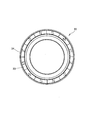
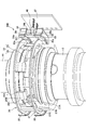
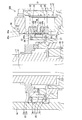
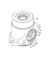
- FIG. 1 is a longitudinal sectional view of an electric power steering apparatus to which a torque sensor according to a first embodiment of the present invention is applied. It is the elements on larger scale of FIG. It is a bottom view of a magnetism generation part. It is a perspective view of the torque sensor which concerns on 1st Embodiment of this invention, and is a figure of the state which removed the housing. It is a perspective view of a rotating magnetic circuit part. It is a perspective view of a sensor holder. It is a perspective view of a magnetism collection yoke.
- the steering shaft 10 and the output shaft 12 rotate in conjunction with the steering wheel, and the wheels are moved by moving the rack shaft meshing with the pinion provided at the lower end of the output shaft 12 in the axial direction. To steer.
- the electric power steering apparatus 1 includes a worm wheel coupled to the output shaft 12, a worm meshing with the worm wheel, and an electric motor that rotationally drives the worm as an assist mechanism that assists in providing steering torque. Prepare.
- the electric power steering device 1 applies steering assist torque to the output shaft 12 by an electric motor.
- the steering shaft 10 includes an input shaft 11 as a first shaft and a torsion bar 21 connected to the input shaft 11.
- the input shaft 11 is rotatably supported by the housing 30 via a rolling bearing 37.
- the output shaft 12 as the second shaft is rotatably supported by the housing 49 via the rolling bearing 38.
- a sliding bearing 39 is interposed between the lower end side of the input shaft 11 and the upper end side of the output shaft 12.
- the input shaft 11 and the output shaft 12 are supported by the housings 30 and 49 so as to be rotatable on the same axis.
- the input shaft 11 is formed in a cylindrical shape, and a torsion bar 21 is accommodated coaxially inside the input shaft 11.
- the upper end portion of the torsion bar 21 is connected to the upper end portion of the input shaft 11 via a pin 28.
- a lower end portion of the torsion bar 21 protrudes from a lower end opening portion of the input shaft 11 and is connected to the output shaft 12 via a serration 29.
- the torsion bar 21 transmits the steering torque input to the input shaft 11 to the output shaft 12 via the steering wheel, and is torsionally deformed around the rotation axis O in accordance with the steering torque.
- the electric power steering apparatus 1 is provided with a non-contact type torque sensor 100 that detects a steering torque acting on a torsion bar 21 that connects the input shaft 11 and the output shaft 12.
- a non-contact type torque sensor 100 that detects a steering torque acting on a torsion bar 21 that connects the input shaft 11 and the output shaft 12.
- the torque sensor 100 includes a magnetic generator 22 that is fixed to the input shaft 11 and rotates with the input shaft 11, a rotating magnetic circuit unit 25 that is fixed to the output shaft 12 and rotates with the output shaft 12, and a fixed magnet that is fixed to the housing 30.
- the torque sensor 100 detects the steering torque acting on the torsion bar 21 based on the output of the magnetic sensor 48.
- the magnetism generating unit 22 may be fixed to the output shaft 12 so as to rotate with the output shaft 12, and the rotating magnetic circuit unit 25 may be fixed to the input shaft 11 so as to rotate with the input shaft 11. .
- the magnetism generator 22 includes an annular back yoke 24 that is press-fitted into the input shaft 11, and an annular ring magnet 23 that is coupled to the lower end surface of the back yoke 24.
- the ring magnet 23 is an annular permanent magnet that generates magnetism in the direction of the rotation axis O of the input shaft 11.
- the ring magnet 23 is a multipolar magnet formed by magnetizing a hard magnetic material in the direction of the rotation axis O, and has 12 magnetic poles formed with an equal width in the circumferential direction. That is, on the upper end surface and the lower end surface of the ring magnet 23, six N poles and six S poles are alternately arranged in the circumferential direction.
- the number of magnetic poles formed on the end face of the ring magnet 23 is arbitrarily set within a range of 2 or more.
- the upper magnetic pole surface which is the upper end surface of the ring magnet 23 is fixed to the lower end surface of the back yoke 24 via an adhesive. Further, since the back yoke 24 is formed of a soft magnetic material, it is magnetized by the magnetic field exerted by the ring magnet 23 and is attracted to the ring magnet 23. Thus, the ring magnet 23 and the back yoke 24 are coupled by the adhesive force and magnetic force of the adhesive.
- the back yoke 24 has a function as a connecting member for connecting the ring magnet 23 to the input shaft 11 and a function as a yoke for connecting the magnetic poles adjacent to the ring magnet 23 to guide the magnetic flux.
- the magnetic force is concentrated on the lower magnetic pole surface which is the end face.
- the rotating magnetic circuit unit 25 includes a first soft magnetic ring 26 and a second soft magnetism to which a magnetic flux generated from the ring magnet 23 of the magnetism generating unit 22 is guided.
- the first soft magnetic ring 26 includes an annular first magnetic path ring portion 26C, six first magnetic path column portions 26B protruding downward from the first magnetic path ring portion 26C, and each first magnetic path column portion.
- a first magnetic path front end portion 26A that refracts inward from the lower end of 26B and faces the lower end surface of the ring magnet 23.
- the second soft magnetic ring 27 includes an annular second magnetic path ring portion 27C, six second magnetic path column portions 27B protruding upward from the second magnetic path ring portion 27C, and each second magnetic path column portion.
- the second magnetic path tip portion 27A is refracted inward from the upper end of 27B and faces the lower end surface of the ring magnet 23.
- the first soft magnetic ring 26 and the second soft magnetic ring 27 are each formed by pressing.
- the first soft magnetic ring 26 and the second soft magnetic ring 27 are not limited to pressing, and may be formed by casting, sintering, or the like.
- the first magnetic path tip portion 26A and the second magnetic path tip portion 27A are formed in a flat plate shape.
- the first magnetic path tip end portion 26A and the second magnetic path tip end portion 27A are arranged on the same plane orthogonal to the rotation axis O of the torsion bar 21 alternately at equal intervals in the circumferential direction around the rotation axis O.
- first magnetic path tip portion 26A and the second magnetic path tip portion 27A are in a neutral state where no torque acts on the torsion bar 21, and the respective center lines extending in the radial direction of the torsion bar 21 are the ring magnets 23. It arrange
- the first magnetic path column portion 26B and the second magnetic path column portion 27B are each formed in a flat plate shape and extend in the direction of the rotation axis O.
- the first magnetic path column portion 26 ⁇ / b> B is disposed so as to surround the outer peripheral surface of the ring magnet 23 with a predetermined gap.
- the first magnetic path column part 26 ⁇ / b> B is provided so as not to short-circuit the magnetic flux of the ring magnet 23.
- the second magnetic path column portion 27B extends along the rotation axis O in the direction opposite to the first magnetic path column portion 26B.
- the first magnetic path ring portion 26C and the second magnetic path ring portion 27C are arranged on a plane orthogonal to the rotation axis O, and are formed in an annular shape with the entire circumference connected.
- the first magnetic path ring portion 26 ⁇ / b> C and the second magnetic path ring portion 27 ⁇ / b> C are not limited to this shape, and may be a C shape in which a slit is partially formed.
- the first magnetic path ring portion 26C is disposed above the lower end surface of the ring magnet 23, and the second magnetic path ring portion 27C is disposed below the ring magnet 23. That is, the ring magnet 23 is disposed between the first magnetic path ring portion 26C and the second magnetic path ring portion 27C in the rotation axis O direction.
- the fixed magnetic circuit portion 31 is provided along the outer periphery of the first magnetic path ring portion 26 ⁇ / b> C of the first soft magnetic ring 26.
- a magnetic yoke 34 and a second magnetic collecting yoke 35 connected to the second magnetic collecting ring 33 are provided.
- FIG. 4 a part of the first magnetism collecting ring 32 and the second magnetism collecting ring 33 is not shown.
- the first magnetism collecting ring 32 and the second magnetism collecting ring 33 have a C shape in which slits are partially formed, and are caulked and fixed to the inner peripheral surface of the housing 30.
- the inner peripheral surface of the first magnetic flux collecting ring 32 faces the first magnetic path ring portion 26C of the first soft magnetic ring 26, and the inner peripheral surface of the second magnetic flux collecting ring 33 is the second magnetic field of the second soft magnetic ring 27. It faces the road ring portion 27C.
- the first magnetism collecting ring 32 and the second magnetism collecting ring 33 are arranged on the outer periphery of the rotating magnetic circuit unit 25, and alleviate the influence of rotational shake and eccentricity of the rotating magnetic circuit unit 25, thereby reducing the magnetic sensor 48 side. Has the function of guiding the magnetic flux to the
- the first magnetic flux collecting yoke 34 is formed in a block shape having an arc-shaped inner circumferential surface 34 a that abuts the outer circumferential surface of the first magnetic flux collecting ring 32, and the second magnetic flux collecting yoke 35 is an outer circumferential surface of the second magnetic flux collecting ring 33. Is formed in a block shape having an arcuate inner peripheral surface 35a that abuts on the inner surface.
- the first magnetic flux collecting yoke 34 has a pair of magnetic flux collecting projections 34b extending in the direction of the rotational axis O
- the second magnetic flux collecting yoke 35 has a pair of magnetic flux collecting convex portions 35b extending in the direction of the rotational axis O.
- the pair of magnetic flux collecting convex portions 34b of the first magnetic flux collecting yoke 34 and the pair of magnetic flux collecting convex portions 35b of the second magnetic flux collecting yoke 35 face each other with a magnetic gap that is a predetermined gap. That is, a pair of magnetic gaps arranged in the circumferential direction is formed between the first magnetism collecting yoke 34 and the second magnetism collecting yoke 35.
- a magnetic sensor 48 is installed in each magnetic gap.
- the first magnetism collecting yoke 34 and the second magnetism collecting yoke 35 have a function of collecting the magnetic flux from the rotating magnetic circuit unit 25 to the magnetic sensor 48 via the first magnetism collecting ring 32 and the second magnetism collecting ring 33.
- the first magnetism collecting yoke 34, the second magnetism collecting yoke 35, the magnetic sensor 48, and the substrate 47 are fixed to the sensor holder 40 through a mold resin.
- the resin-made sensor holder 40 is attached to the metal housing 30 via a bolt inserted into the fastening hole 40b while the cylindrical portion 40a is fitted into the opening 30a of the housing 30.
- a Hall element is used for the magnetic sensor 48 for detecting magnetism.
- the hall element outputs a voltage corresponding to the magnetic flux density passing therethrough as a signal.
- the magnetic sensor 48 outputs a voltage corresponding to the magnitude and direction of the magnetic field of the magnetic gap through the substrate 47 and the terminal 44.
- the terminal 44 is connected to the controller via wiring connected to the sensor holder 40.
- the magnetic sensor 48 may include a circuit that amplifies a Hall element signal, a temperature compensation circuit, and a noise filter circuit.
- a pair of magnetic sensors 48 are provided corresponding to a pair of magnetic gaps arranged in the circumferential direction formed between the first magnetism collecting yoke 34 and the second magnetism collecting yoke 35, one being a main system and the other being a sub system.
- an output voltage output from the magnetic sensor 48 of the main system is used.
- the output voltage output from the magnetic sensor 48 of the sub system is used for diagnosing abnormality of the torque sensor 100 by the controller. Specifically, the controller compares the steering torque detected in the main system and the steering torque detected in the sub system, and determines that the difference is greater than or equal to a predetermined tolerance. It is determined that an abnormality has occurred in the torque sensor 100.
- the first magnetic path tip end portion 26 A of the first soft magnetic ring 26 and the second magnetic path tip end portion 27 A of the second soft magnetic ring 27 are respectively N of the ring magnet 23. Opposite the pole and the S pole with the same area and magnetically short-circuit both. Therefore, the magnetic flux is not guided to the rotating magnetic circuit unit 25 and the fixed magnetic circuit unit 31.
- the torsion bar 21 When a torque in a specific direction acts on the torsion bar 21 by the steering wheel operation by the driver, the torsion bar 21 is twisted and deformed according to the direction of the torque.
- the first magnetic path tip 26A faces the N pole with a larger area than the S pole, while the second magnetic path tip 27A has a larger area at the S pole than the N pole. Confront.
- the magnetic flux from the ring magnet 23 is guided to the fixed magnetic circuit unit 31 through the rotating magnetic circuit unit 25.
- the first soft magnetic ring 26, the first magnetic flux collecting ring 32, the first magnetic flux collecting yoke 34, the second magnetic flux collecting yoke 35, the second magnetic flux collecting ring 33, and the second soft magnetic ring 27 are arranged from the N pole. This is a route that goes to the south pole.
- the magnetic sensor 48 installed in the magnetic gap between the first magnetic collecting yoke 34 and the second magnetic collecting yoke 35 outputs a signal corresponding to the magnitude and direction of the magnetic flux.
- the torsion bar 21 when a torque in the opposite direction to the above acts on the torsion bar 21 by the operation of the steering wheel by the driver, the torsion bar 21 is twisted and deformed in the opposite direction according to the direction of the torque.
- the first magnetic path tip 26A opposes with a larger area than the N pole with the S pole, while the second magnetic path tip 27A has a larger area with the N pole than the S pole.
- the magnetic flux from the ring magnet 23 is guided to the fixed magnetic circuit unit 31 through the rotating magnetic circuit unit 25, but has a path opposite to the above.
- the second soft magnetic ring 27, the second magnetic flux collecting ring 33, the second magnetic flux collecting yoke 35, the first magnetic flux collecting yoke 34, the first magnetic flux collecting ring 32, and the first soft magnetic ring 26 are arranged from the N pole. This is a route that goes to the south pole.
- the magnetic sensor 48 installed in the magnetic gap between the first magnetic collecting yoke 34 and the second magnetic collecting yoke 35 outputs a signal corresponding to the magnitude and direction of the magnetic flux.
- the magnetic flux induced in the gap increases and the output signal of the magnetic sensor 48 also increases. Therefore, the magnetic flux density guided to the magnetic sensor 48 can be increased by increasing the number of magnetic poles of the ring magnet 23.
- the torsion bar 21 is torsionally deformed, and the first magnetic path tip 26A of the first soft magnetic ring 26 faces with a larger area from the S pole to the N pole, and the second soft magnetic ring 27
- a solid line arrow shows the path
- a dotted line arrow shows the path
- Leakage magnetic flux is guided from the first soft magnetic ring 26 to the second soft magnetic ring 27 by bypassing the magnetic sensor 48.
- the leakage magnetic flux path (indicated by the curved arrow in FIG. 23) that short-circuits the first soft magnetic ring 26 and the second soft magnetic ring 27 in the rotating magnetic circuit unit 25. Route) exists.
- the ring magnet 23 has six pairs of N poles and S poles, there are six magnetic flux paths that short-circuit the first soft magnetic ring 26 and the second soft magnetic ring 27.
- FIG. 9 is a graph showing the detection error of the torque sensor 100 due to the influence of the leakage magnetic flux.
- the horizontal axis in FIG. 9 is the rotation angle of the input shaft 11, and the vertical axis is the steering torque (detected torque) detected by the torque sensor 100.
- the solid line is the detected torque of the main system, and the dotted line is the detected torque of the sub system.
- FIG. 9 shows the detected torque of the torque sensor 100 when the input shaft 11 is rotated once so that the steering torque acting on the torsion bar 21 is constant. Since the steering torque acting on the torsion bar 21 is constant, the torque detected by the torque sensor 100 should be constant. However, the torque detected by the torque sensor 100 changes at a cycle of 60 ° as shown in FIG. This is because there are six paths of leakage flux that short-circuit the first soft magnetic ring 26 and the second soft magnetic ring 27 as described above, and the six leakage fluxes become lighter and darker as the input shaft 11 rotates. This is because it was detected. As described above, the torque sensor 100 also detects a change in leakage flux that depends on the rotation angle of the input shaft 11, that is, a change in leakage flux that is not related to the torsional deformation of the torsion bar 14.
- the magnetic sensor 48 detects a change (error component) in the leakage magnetic flux that is not related to the torsional deformation of the torsion bar 14, the magnetic sensor 48 twists the torsion bar 14 to the true magnetic flux density accompanying the torsional deformation of the torsion bar 14. Therefore, a magnetic flux density on which a change in leakage magnetic flux that is irrelevant is superimposed is detected, and a detection error occurs in the torque sensor 100.
- a detection error occurs in the torque sensor 100, an error occurs in the steering assist torque applied to the output shaft 12 by the electric motor. Therefore, when high-precision control is required by the electric power steering apparatus 1, it is necessary to prevent a detection error of the torque sensor 100 due to a change in leakage magnetic flux that is unrelated to the torsional deformation of the torsion bar 14.
- a shielding plate 50 for guiding the leakage flux and magnetically shielding the magnetic sensor 48 against the leakage flux is disposed.
- the shielding plate 50 has an arc shape having substantially the same radius of curvature as the inner peripheral surfaces 34a and 35a of the first magnetism collecting yoke 34 and the second magnetism collecting yoke 35, and is made of a magnetic material, specifically a soft magnetic material. Formed.
- the shielding plate 50 is integrally formed with the first magnetism collecting yoke 34 and the second magnetism collecting yoke 35 in the sensor holder 40 (see FIG. 6) via a molding resin. Specifically, the shielding plate 50 is fixed to a mold resin 51 (see FIG. 2) that is formed between the first magnetism collecting yoke 34 and the second magnetism collecting yoke 35 and supports both.
- the shielding plate 50 and the mold resin 51 are integrally molded by insert molding or outsert molding.
- the shielding plate 50 has a predetermined gap 52, 53 between the first magnetic flux collecting yoke 34 and the second magnetic flux collecting yoke 35 so that the inner circumferential surface 50a is flush with the inner circumferential surfaces 34a, 35a. It is arranged with a gap.
- the shielding plate 50 By arranging the shielding plate 50 between the first magnetism collecting yoke 34 and the second magnetism collecting yoke 35, leakage magnetic flux in the rotary magnetic circuit unit 25 is guided to the shielding plate 50 and does not reach the magnetic sensor 48. .
- the magnetic sensor 48 since the magnetic sensor 48 is magnetically shielded against the leakage magnetic flux in the rotating magnetic circuit unit 25 by the shielding plate 50, the change in the leakage magnetic flux not related to the torsional deformation of the torsion bar 14 is detected. Unaffected. Therefore, the detection error of the torque sensor 100 is eliminated, and the detection accuracy of the torque sensor 100 is increased.
- the gaps 52 and 53 are set to dimensions that can magnetically shield the magnetic sensor 48 against leakage magnetic flux in the rotating magnetic circuit unit 25 while suppressing a decrease in the detected magnetic flux density of the magnetic sensor 48. Is done.
- the leakage magnetic flux in the rotary magnetic circuit unit 25 is guided to the shielding plate 55 and is then transmitted from the first magnetism collecting yoke 34 to the first magnetism collecting yoke 34.
- the magnetic sensor 48 is guided to the second magnetic flux collecting yoke 35 or from the second magnetic flux collecting yoke 35 to the first magnetic flux collecting yoke 34.
- the shielding plate 50 by providing the shielding plate 50, the detection error of the torque sensor 100 due to the leakage magnetic flux in the rotating magnetic circuit unit 25 is eliminated, so that the magnetic sensor 48 can be disposed close to the input / output shafts 11 and 12. Thus, the torque sensor 100 can be reduced in size.
- the torque sensor 200 is different from the first embodiment in the configuration of the shielding plate 60 that induces a leakage flux between the first magnetism collecting yoke 34 and the second magnetism collecting yoke 35.
- the shielding plate 50 is formed separately from the first magnetism collecting yoke 34 and the second magnetism collecting yoke 35, but the shielding plate 60 in the torque sensor 200 is the first magnetism collecting yoke 34.
- the magnetic yoke 34 and the second magnetic flux collecting yoke 35 are integrally formed.
- the shielding plate 60 will be described in detail.
- Each of the first magnetism collecting yoke 34 and the second magnetism collecting yoke 35 has a first extension portion 34c and a second extension portion 35c formed by extending a part thereof.
- the first extension part 34c and the second extension part 35c are formed to extend toward each other, and are arranged to face each other with a predetermined gap 61 therebetween.
- the shielding plate 60 includes a first extension portion 34 c and a second extension portion 35 c that are arranged to face each other with a predetermined gap 61 therebetween, and is arranged between the rotating magnetic circuit unit 25 and the magnetic sensor 48.
- the shielding plate 60 has the same function as the shielding plate 50 in the first embodiment. That is, the shielding plate 60 induces a leakage flux between the first magnetism collecting yoke 34 and the second magnetism collecting yoke 35 and magnetically shields the magnetic sensor 48 against the leakage flux.
- the gap 61 between the first extension 34c and the second extension 35c prevents the leakage flux in the rotating magnetic circuit unit 25 while suppressing a decrease in the detected magnetic flux density of the magnetic sensor 48.
- the dimension is set such that the magnetic sensor 48 can be shielded magnetically.
- the shielding plate 55 formed integrally with the first magnetism collecting yoke 34 and the second magnetism collecting yoke 35 By providing the shielding plate 55 formed integrally with the first magnetism collecting yoke 34 and the second magnetism collecting yoke 35, the leakage magnetic flux in the rotary magnetic circuit section 25 is guided to the shielding plate 55, and the first magnetism collecting yoke.
- the magnetic sensor 48 is bypassed and guided from 34 to the second magnetic collecting yoke 35 or from the second magnetic collecting yoke 35 to the first magnetic collecting yoke 34.
- the magnetic sensor 48 since the leakage magnetic flux in the rotating magnetic circuit unit 25 does not reach the magnetic sensor 48, the magnetic sensor 48 is not affected by the change of the leakage magnetic flux that is not related to the torsional deformation of the torsion bar 14. Therefore, the detection error of the torque sensor 100 due to the leakage magnetic flux in the rotating magnetic circuit unit 25 is eliminated, and the detection accuracy of the torque sensor 100 is increased.
- the shielding plate 60 by providing the shielding plate 60, the detection error of the torque sensor 200 due to the leakage magnetic flux in the rotary magnetic circuit unit 25 is eliminated, so that the magnetic sensor 48 can be disposed close to the input / output shafts 11 and 12. Thus, the torque sensor 200 can be reduced in size.
- the shielding plate 60 includes a first extending portion 34c and a second extending portion 35c obtained by extending a part of the first and second magnetic collecting yokes 34 and 35, the shielding plate 50 is provided with the first collecting yoke.
- the torque sensor 100 according to the first embodiment provided separately from the 34 and the second magnetism collecting yoke 35 the number of parts can be reduced.
- a torque sensor 300 according to a third embodiment of the present invention will be described with reference to FIGS.
- the same components as those in the first embodiment will be denoted by the same reference numerals and description thereof will be omitted.
- a shielding plate 55 is disposed.
- the shielding plate 55 has an arc shape having substantially the same radius of curvature as the first magnetism collecting ring 32 and the second magnetism collecting ring 33, and has the same thickness as the first magnetism collecting ring 32 and the second magnetism collecting ring 33.
- the shielding plate 55 is made of a magnetic material, specifically, a soft magnetic material.
- the shielding plate 55 is integrally formed with the housing 30. Specifically, as shown in FIG. 6, the shielding plate 55 is fixed to a resin material 56 that is coupled to the inner peripheral surface of the opening 30a of the housing 30 and is formed so as to cross the opening 30a.
- the shielding plate 55 and the resin material 56 are integrally formed by insert molding or outsert molding. At both ends of the shielding plate 55, notches 55a into which pins for positioning the shielding plate 55 are fitted when the shielding plate 55 and the resin material 56 are integrally molded are formed.
- the shielding plate 55 may be integrally molded with the sensor holder 40. In that case, the shielding plate 55 is fixed to a mold resin 51 (see FIG. 2) that is formed between the first magnetism collecting yoke 34 and the second magnetism collecting yoke 35 and supports both.
- the shield plate 55 is disposed between the first magnetism collecting ring 32 and the second magnetism collecting ring 33 with predetermined gaps 57 and 58 therebetween.
- the shielding plate 55 By arranging the shielding plate 55 between the first magnetism collecting ring 32 and the second magnetism collecting ring 33, leakage magnetic flux in the rotating magnetic circuit unit 25 is guided to the shielding plate 55 and does not reach the magnetic sensor 48. .
- the magnetic sensor 48 is magnetically shielded against the leakage magnetic flux in the rotating magnetic circuit unit 25 by the shielding plate 55, the change in the leakage magnetic flux not related to the torsional deformation of the torsion bar 14 is caused. Unaffected. Therefore, the detection error of the torque sensor 300 is eliminated, and the detection accuracy of the torque sensor 300 is increased.
- the gaps 57 and 58 are set to dimensions capable of magnetically shielding the magnetic sensor 48 against leakage magnetic flux in the rotating magnetic circuit unit 25 while suppressing a decrease in the detected magnetic flux density of the magnetic sensor 48. Is done.
- the leakage magnetic flux in the rotary magnetic circuit unit 25 is guided to the shielding plate 55 and is then transmitted from the first magnetism collecting ring 32.
- the magnetic sensor 48 is guided to the second magnetism collecting ring 33 or from the second magnetism collecting ring 33 to the first magnetism collecting ring 32.
- the magnetic sensor 48 can be disposed close to the input / output shafts 11 and 12.
- the torque sensor 300 can be reduced in size.
- the torque sensor 400 is different from the third embodiment in the configuration of the shielding plate 65 that induces a leakage flux between the first magnetism collecting ring 32 and the second magnetism collecting ring 33.
- the shielding plate 55 is formed separately from the first magnetism collecting ring 32 and the second magnetism collecting ring 33, but the shielding plate 65 in the torque sensor 400 is the first magnetism collecting ring 32.
- the magnetic ring 32 and the second magnetic flux collecting ring 33 are integrally formed.
- the shielding plate 65 will be described in detail.
- Each of the first magnetism collecting ring 32 and the second magnetism collecting ring 33 has a first extension part 32a and a second extension part 33a formed by extending a part thereof.
- the first extension portion 32a and the second extension portion 33a are formed so as to extend toward each other, and are disposed to face each other with a predetermined gap 66 therebetween.
- the shielding plate 65 includes a first extension portion 32 a and a second extension portion 33 a that are arranged to face each other with a predetermined gap 66 therebetween, and is arranged between the rotating magnetic circuit portion 25 and the magnetic sensor 48.
- the shielding plate 65 has the same function as the shielding plate 55 in the first embodiment. That is, the shielding plate 65 induces a leakage flux between the first magnetism collecting ring 32 and the second magnetism collecting ring 33 and magnetically shields the magnetic sensor 48 against the leakage flux.
- the gap 66 between the first extension portion 32a and the second extension portion 33a suppresses a decrease in the detected magnetic flux density of the magnetic sensor 48, and prevents leakage magnetic flux in the rotating magnetic circuit portion 25.
- the dimension is set such that the magnetic sensor 48 can be shielded magnetically.
- the leakage flux in the rotary magnetic circuit unit 25 is induced to the shielding plate 55 and the first magnetism collecting ring.
- the magnetic sensor 48 is guided by bypassing the magnetic sensor 48 from the second magnetic flux collecting ring 33 to the second magnetic flux collecting ring 33 or from the second magnetic flux collecting ring 33 to the first magnetic flux collecting ring 32.
- the magnetic sensor 48 since the leakage magnetic flux in the rotating magnetic circuit unit 25 does not reach the magnetic sensor 48, the magnetic sensor 48 is not affected by the change of the leakage magnetic flux that is not related to the torsional deformation of the torsion bar 14. Therefore, the detection error of the torque sensor 400 due to the leakage magnetic flux in the rotating magnetic circuit unit 25 is eliminated, and the detection accuracy of the torque sensor 400 is increased.
- the shielding plate 65 by providing the shielding plate 65, the detection error of the torque sensor 400 caused by the leakage magnetic flux in the rotating magnetic circuit unit 25 is eliminated, so that the magnetic sensor 48 can be disposed close to the input / output shafts 11 and 12. Thus, the torque sensor 400 can be reduced in size.
- the shielding plate 65 includes a first extension portion 32a and a second extension portion 33a obtained by extending a part of the first magnetism collecting ring 32 and the second magnetism collecting ring 33, the shielding plate 55 serves as the first magnetism collecting ring. 32 and the second magnetism collecting ring 33, the number of parts can be reduced as compared with the torque sensor 300 according to the third embodiment provided separately.
- the present invention can be used as a torque sensor used in an electric power steering device that assists a steering force applied by a driver to a steering wheel.
Landscapes
- Physics & Mathematics (AREA)
- General Physics & Mathematics (AREA)
- Engineering & Computer Science (AREA)
- Electromagnetism (AREA)
- Chemical & Material Sciences (AREA)
- Combustion & Propulsion (AREA)
- Transportation (AREA)
- Mechanical Engineering (AREA)
- Power Steering Mechanism (AREA)
Abstract
La présente invention concerne un capteur de couple comportant : une section génératrice de magnétisme, qui tourne avec un premier arbre ; une section tournante de circuit magnétique, qui tourne avec un deuxième arbre ; une section fixe de circuit magnétique, qui est fixée à un carter ; un détecteur magnétique, qui détecte la densité d'un flux magnétique qui est acheminé de la section génératrice de magnétisme à la section fixe de circuit magnétique par l'intermédiaire de la section tournante de circuit magnétique en raison d'une déformation de torsion d'une barre de torsion ; et une plaque d'occultation, qui est disposée entre la section tournante de circuit magnétique et le détecteur magnétique et qui occulte magnétiquement le détecteur magnétique.
Priority Applications (3)
| Application Number | Priority Date | Filing Date | Title |
|---|---|---|---|
| CN201380013190.4A CN104169701B (zh) | 2012-03-22 | 2013-01-31 | 力矩传感器 |
| US14/386,397 US9435703B2 (en) | 2012-03-22 | 2013-01-31 | Torque sensor |
| EP13763845.8A EP2829858B1 (fr) | 2012-03-22 | 2013-01-31 | Capteur de couple |
Applications Claiming Priority (4)
| Application Number | Priority Date | Filing Date | Title |
|---|---|---|---|
| JP2012065765A JP5852485B2 (ja) | 2012-03-22 | 2012-03-22 | トルクセンサ |
| JP2012-065755 | 2012-03-22 | ||
| JP2012065755A JP5852484B2 (ja) | 2012-03-22 | 2012-03-22 | トルクセンサ |
| JP2012-065765 | 2012-03-22 |
Publications (1)
| Publication Number | Publication Date |
|---|---|
| WO2013140864A1 true WO2013140864A1 (fr) | 2013-09-26 |
Family
ID=49222331
Family Applications (1)
| Application Number | Title | Priority Date | Filing Date |
|---|---|---|---|
| PCT/JP2013/052257 Ceased WO2013140864A1 (fr) | 2012-03-22 | 2013-01-31 | Capteur de couple |
Country Status (4)
| Country | Link |
|---|---|
| US (1) | US9435703B2 (fr) |
| EP (1) | EP2829858B1 (fr) |
| CN (1) | CN104169701B (fr) |
| WO (1) | WO2013140864A1 (fr) |
Cited By (1)
| Publication number | Priority date | Publication date | Assignee | Title |
|---|---|---|---|---|
| JP2022515161A (ja) * | 2018-12-21 | 2022-02-17 | エルジー イノテック カンパニー リミテッド | センシング装置 |
Families Citing this family (14)
| Publication number | Priority date | Publication date | Assignee | Title |
|---|---|---|---|---|
| US10466121B2 (en) * | 2014-03-06 | 2019-11-05 | Joyson Safety Systems Acquisition Llc | Force-based detection systems and methods |
| CN106794870B (zh) * | 2014-08-28 | 2019-04-19 | 乐星汽车科技有限公司 | 扭矩传感器设备 |
| EP3196101A1 (fr) * | 2014-08-28 | 2017-07-26 | LS Automotive Corp | Dispositif capteur de couple |
| FR3035504B1 (fr) * | 2015-04-21 | 2017-04-21 | Continental Automotive France | Capteur de mesure du couple d'un arbre d'entrainement |
| JP6565065B2 (ja) * | 2016-06-08 | 2019-08-28 | 日立オートモティブシステムズ株式会社 | トルクセンサ |
| JP6791065B2 (ja) * | 2017-04-28 | 2020-11-25 | 株式会社Soken | トルク検出装置及びセンサモジュール |
| JP6791912B2 (ja) * | 2017-09-01 | 2020-11-25 | 株式会社Soken | トルク検出装置、及び、磁気センサモジュール |
| JP7124566B2 (ja) * | 2018-08-29 | 2022-08-24 | 株式会社ジェイテクト | センサ装置 |
| CN111256897A (zh) * | 2018-11-30 | 2020-06-09 | 长城汽车股份有限公司 | 扭矩传感器以及车辆 |
| DE102018131712A1 (de) * | 2018-12-11 | 2020-06-18 | Thyssenkrupp Ag | Magnetische Abschirmung eines Drehmomentsensors für eine elektromechanische Hilfskraftlenkung eines Kraftfahrzeugs |
| JP6988851B2 (ja) * | 2019-03-20 | 2022-01-05 | Tdk株式会社 | 磁界発生ユニット、位置検出装置及び磁界発生ユニットの製造方法 |
| FR3112524B1 (fr) * | 2020-07-20 | 2024-02-23 | Moving Magnet Tech | Organe d’entrainement de cycle presentant un capteur de couple |
| EP4163597A1 (fr) * | 2021-10-06 | 2023-04-12 | thyssenkrupp Presta Aktiengesellschaft | Système de direction pour véhicule automobile |
| KR20240103429A (ko) * | 2022-12-27 | 2024-07-04 | 엘지이노텍 주식회사 | 센서 장치 |
Citations (6)
| Publication number | Priority date | Publication date | Assignee | Title |
|---|---|---|---|---|
| JPH0348714U (fr) * | 1989-09-19 | 1991-05-10 | ||
| JP2004309463A (ja) * | 2003-04-04 | 2004-11-04 | Valeo Schalter & Sensoren Gmbh | シャフトに加えられるトルクを測定する装置 |
| JP2006162557A (ja) * | 2004-12-10 | 2006-06-22 | Kayaba Ind Co Ltd | トルクセンサ |
| JP2008203176A (ja) * | 2007-02-22 | 2008-09-04 | Nsk Ltd | トルクセンサ及びこれを使用した電動パワーステアリング装置 |
| JP2009244205A (ja) | 2008-03-31 | 2009-10-22 | Kayaba Ind Co Ltd | トルクセンサ |
| JP2011209005A (ja) * | 2010-03-29 | 2011-10-20 | Hitachi Cable Ltd | トルクインデックスセンサ |
Family Cites Families (9)
| Publication number | Priority date | Publication date | Assignee | Title |
|---|---|---|---|---|
| US4984474A (en) | 1988-09-30 | 1991-01-15 | Copal Company Limited | Torque sensor |
| US6926115B2 (en) * | 2002-07-31 | 2005-08-09 | Hitachi Cable, Ltd. | Angle sensor, angle-torque sensor and electric power steering unit using same |
| JP4190849B2 (ja) * | 2002-10-07 | 2008-12-03 | 株式会社日本自動車部品総合研究所 | トルクセンサ |
| JP4871014B2 (ja) * | 2006-04-24 | 2012-02-08 | カヤバ工業株式会社 | トルクセンサ |
| JP2011013133A (ja) * | 2009-07-03 | 2011-01-20 | Kyb Co Ltd | トルクセンサ |
| JP5513902B2 (ja) * | 2010-01-12 | 2014-06-04 | カヤバ工業株式会社 | トルクセンサ |
| JP5994264B2 (ja) * | 2012-02-01 | 2016-09-21 | 株式会社ジェイテクト | トルク検出装置およびその製造方法 |
| JP5994286B2 (ja) * | 2012-02-28 | 2016-09-21 | 株式会社ジェイテクト | トルク検出装置およびその製造方法 |
| JP5675700B2 (ja) * | 2012-05-25 | 2015-02-25 | 株式会社日本自動車部品総合研究所 | トルクセンサ |
-
2013
- 2013-01-31 CN CN201380013190.4A patent/CN104169701B/zh active Active
- 2013-01-31 US US14/386,397 patent/US9435703B2/en active Active
- 2013-01-31 WO PCT/JP2013/052257 patent/WO2013140864A1/fr not_active Ceased
- 2013-01-31 EP EP13763845.8A patent/EP2829858B1/fr active Active
Patent Citations (6)
| Publication number | Priority date | Publication date | Assignee | Title |
|---|---|---|---|---|
| JPH0348714U (fr) * | 1989-09-19 | 1991-05-10 | ||
| JP2004309463A (ja) * | 2003-04-04 | 2004-11-04 | Valeo Schalter & Sensoren Gmbh | シャフトに加えられるトルクを測定する装置 |
| JP2006162557A (ja) * | 2004-12-10 | 2006-06-22 | Kayaba Ind Co Ltd | トルクセンサ |
| JP2008203176A (ja) * | 2007-02-22 | 2008-09-04 | Nsk Ltd | トルクセンサ及びこれを使用した電動パワーステアリング装置 |
| JP2009244205A (ja) | 2008-03-31 | 2009-10-22 | Kayaba Ind Co Ltd | トルクセンサ |
| JP2011209005A (ja) * | 2010-03-29 | 2011-10-20 | Hitachi Cable Ltd | トルクインデックスセンサ |
Cited By (2)
| Publication number | Priority date | Publication date | Assignee | Title |
|---|---|---|---|---|
| JP2022515161A (ja) * | 2018-12-21 | 2022-02-17 | エルジー イノテック カンパニー リミテッド | センシング装置 |
| JP7510421B2 (ja) | 2018-12-21 | 2024-07-03 | エルジー イノテック カンパニー リミテッド | センシング装置 |
Also Published As
| Publication number | Publication date |
|---|---|
| CN104169701B (zh) | 2016-03-30 |
| US20150040686A1 (en) | 2015-02-12 |
| EP2829858A1 (fr) | 2015-01-28 |
| EP2829858A4 (fr) | 2015-09-30 |
| CN104169701A (zh) | 2014-11-26 |
| US9435703B2 (en) | 2016-09-06 |
| EP2829858B1 (fr) | 2019-09-11 |
Similar Documents
| Publication | Publication Date | Title |
|---|---|---|
| EP2829858B1 (fr) | Capteur de couple | |
| CN101213431B (zh) | 用于检测角度差的传感器装置 | |
| US9302700B2 (en) | Torque sensor and power steering system using the torque sensor | |
| US9400290B2 (en) | Torque index sensor | |
| EP2314499B1 (fr) | Dispositif à direction assistée | |
| US11180193B2 (en) | Sensor device | |
| JP6144459B2 (ja) | 電動パワーステアリング装置 | |
| JP2018072086A (ja) | 回転角検出装置 | |
| CA2708517A1 (fr) | Detecteur de couple | |
| JP6726593B2 (ja) | トルクセンサ | |
| US20200047790A1 (en) | Magnetic detection device, torque sensor and electric power steering device | |
| JP2014066561A (ja) | 回転角度・トルク検出装置 | |
| JP5852484B2 (ja) | トルクセンサ | |
| EP2868551B1 (fr) | Détecteur embarqué | |
| JP5948100B2 (ja) | トルクセンサ | |
| JP6691071B2 (ja) | トルクセンサ | |
| KR101882550B1 (ko) | 토크 센서 장치 | |
| JP5852485B2 (ja) | トルクセンサ | |
| KR102068187B1 (ko) | 토크앵글센서 | |
| KR20160029989A (ko) | 토크 센서 장치 | |
| JP2018059741A (ja) | トルクセンサの製造方法 | |
| CN110723208A (zh) | 转向辅助装置 | |
| JP2014065367A (ja) | 回転角度・トルク検出装置 | |
| JP2018059740A (ja) | トルクセンサ | |
| JP2014041044A (ja) | トルクセンサ |
Legal Events
| Date | Code | Title | Description |
|---|---|---|---|
| WWE | Wipo information: entry into national phase |
Ref document number: 201380013190.4 Country of ref document: CN |
|
| 121 | Ep: the epo has been informed by wipo that ep was designated in this application |
Ref document number: 13763845 Country of ref document: EP Kind code of ref document: A1 |
|
| WWE | Wipo information: entry into national phase |
Ref document number: 14386397 Country of ref document: US |
|
| WWE | Wipo information: entry into national phase |
Ref document number: 2013763845 Country of ref document: EP |
|
| NENP | Non-entry into the national phase |
Ref country code: DE |