WO2013140924A1 - Unité optique, dispositif de détection de fluorescence, et procédé de détection de fluorescence - Google Patents
Unité optique, dispositif de détection de fluorescence, et procédé de détection de fluorescence Download PDFInfo
- Publication number
- WO2013140924A1 WO2013140924A1 PCT/JP2013/054144 JP2013054144W WO2013140924A1 WO 2013140924 A1 WO2013140924 A1 WO 2013140924A1 JP 2013054144 W JP2013054144 W JP 2013054144W WO 2013140924 A1 WO2013140924 A1 WO 2013140924A1
- Authority
- WO
- WIPO (PCT)
- Prior art keywords
- light
- objective lens
- fluorescence
- lens
- incident
- Prior art date
- Legal status (The legal status is an assumption and is not a legal conclusion. Google has not performed a legal analysis and makes no representation as to the accuracy of the status listed.)
- Ceased
Links
Images




Classifications
-
- G—PHYSICS
- G01—MEASURING; TESTING
- G01N—INVESTIGATING OR ANALYSING MATERIALS BY DETERMINING THEIR CHEMICAL OR PHYSICAL PROPERTIES
- G01N21/00—Investigating or analysing materials by the use of optical means, i.e. using sub-millimetre waves, infrared, visible or ultraviolet light
- G01N21/62—Systems in which the material investigated is excited whereby it emits light or causes a change in wavelength of the incident light
- G01N21/63—Systems in which the material investigated is excited whereby it emits light or causes a change in wavelength of the incident light optically excited
- G01N21/64—Fluorescence; Phosphorescence
- G01N21/645—Specially adapted constructive features of fluorimeters
-
- G—PHYSICS
- G01—MEASURING; TESTING
- G01N—INVESTIGATING OR ANALYSING MATERIALS BY DETERMINING THEIR CHEMICAL OR PHYSICAL PROPERTIES
- G01N21/00—Investigating or analysing materials by the use of optical means, i.e. using sub-millimetre waves, infrared, visible or ultraviolet light
- G01N21/62—Systems in which the material investigated is excited whereby it emits light or causes a change in wavelength of the incident light
- G01N21/63—Systems in which the material investigated is excited whereby it emits light or causes a change in wavelength of the incident light optically excited
- G01N21/64—Fluorescence; Phosphorescence
- G01N21/645—Specially adapted constructive features of fluorimeters
- G01N21/6456—Spatial resolved fluorescence measurements; Imaging
-
- G—PHYSICS
- G01—MEASURING; TESTING
- G01N—INVESTIGATING OR ANALYSING MATERIALS BY DETERMINING THEIR CHEMICAL OR PHYSICAL PROPERTIES
- G01N21/00—Investigating or analysing materials by the use of optical means, i.e. using sub-millimetre waves, infrared, visible or ultraviolet light
- G01N21/62—Systems in which the material investigated is excited whereby it emits light or causes a change in wavelength of the incident light
- G01N21/63—Systems in which the material investigated is excited whereby it emits light or causes a change in wavelength of the incident light optically excited
- G01N21/64—Fluorescence; Phosphorescence
- G01N21/6486—Measuring fluorescence of biological material, e.g. DNA, RNA, cells
-
- G—PHYSICS
- G02—OPTICS
- G02B—OPTICAL ELEMENTS, SYSTEMS OR APPARATUS
- G02B19/00—Condensers, e.g. light collectors or similar non-imaging optics
- G02B19/0004—Condensers, e.g. light collectors or similar non-imaging optics characterised by the optical means employed
- G02B19/0028—Condensers, e.g. light collectors or similar non-imaging optics characterised by the optical means employed refractive and reflective surfaces, e.g. non-imaging catadioptric systems
-
- G—PHYSICS
- G02—OPTICS
- G02B—OPTICAL ELEMENTS, SYSTEMS OR APPARATUS
- G02B19/00—Condensers, e.g. light collectors or similar non-imaging optics
- G02B19/0033—Condensers, e.g. light collectors or similar non-imaging optics characterised by the use
- G02B19/0076—Condensers, e.g. light collectors or similar non-imaging optics characterised by the use for use with a detector
-
- G—PHYSICS
- G02—OPTICS
- G02B—OPTICAL ELEMENTS, SYSTEMS OR APPARATUS
- G02B19/00—Condensers, e.g. light collectors or similar non-imaging optics
- G02B19/0033—Condensers, e.g. light collectors or similar non-imaging optics characterised by the use
- G02B19/0076—Condensers, e.g. light collectors or similar non-imaging optics characterised by the use for use with a detector
- G02B19/008—Condensers, e.g. light collectors or similar non-imaging optics characterised by the use for use with a detector adapted to collect light from a complete hemisphere or a plane extending 360 degrees around the detector
-
- G—PHYSICS
- G02—OPTICS
- G02B—OPTICAL ELEMENTS, SYSTEMS OR APPARATUS
- G02B19/00—Condensers, e.g. light collectors or similar non-imaging optics
- G02B19/0033—Condensers, e.g. light collectors or similar non-imaging optics characterised by the use
- G02B19/0085—Condensers, e.g. light collectors or similar non-imaging optics characterised by the use for use with both a detector and a source
-
- G—PHYSICS
- G02—OPTICS
- G02B—OPTICAL ELEMENTS, SYSTEMS OR APPARATUS
- G02B21/00—Microscopes
- G02B21/0004—Microscopes specially adapted for specific applications
- G02B21/002—Scanning microscopes
- G02B21/0024—Confocal scanning microscopes (CSOMs) or confocal "macroscopes"; Accessories which are not restricted to use with CSOMs, e.g. sample holders
- G02B21/0052—Optical details of the image generation
- G02B21/0076—Optical details of the image generation arrangements using fluorescence or luminescence
-
- G—PHYSICS
- G01—MEASURING; TESTING
- G01N—INVESTIGATING OR ANALYSING MATERIALS BY DETERMINING THEIR CHEMICAL OR PHYSICAL PROPERTIES
- G01N21/00—Investigating or analysing materials by the use of optical means, i.e. using sub-millimetre waves, infrared, visible or ultraviolet light
- G01N21/62—Systems in which the material investigated is excited whereby it emits light or causes a change in wavelength of the incident light
- G01N21/63—Systems in which the material investigated is excited whereby it emits light or causes a change in wavelength of the incident light optically excited
- G01N21/64—Fluorescence; Phosphorescence
- G01N21/645—Specially adapted constructive features of fluorimeters
- G01N2021/6463—Optics
- G01N2021/6471—Special filters, filter wheel
-
- G—PHYSICS
- G01—MEASURING; TESTING
- G01N—INVESTIGATING OR ANALYSING MATERIALS BY DETERMINING THEIR CHEMICAL OR PHYSICAL PROPERTIES
- G01N21/00—Investigating or analysing materials by the use of optical means, i.e. using sub-millimetre waves, infrared, visible or ultraviolet light
- G01N21/62—Systems in which the material investigated is excited whereby it emits light or causes a change in wavelength of the incident light
- G01N21/63—Systems in which the material investigated is excited whereby it emits light or causes a change in wavelength of the incident light optically excited
- G01N21/64—Fluorescence; Phosphorescence
- G01N21/645—Specially adapted constructive features of fluorimeters
- G01N2021/6463—Optics
- G01N2021/6478—Special lenses
-
- G—PHYSICS
- G01—MEASURING; TESTING
- G01N—INVESTIGATING OR ANALYSING MATERIALS BY DETERMINING THEIR CHEMICAL OR PHYSICAL PROPERTIES
- G01N2201/00—Features of devices classified in G01N21/00
- G01N2201/06—Illumination; Optics
- G01N2201/061—Sources
- G01N2201/06113—Coherent sources; lasers
-
- G—PHYSICS
- G01—MEASURING; TESTING
- G01N—INVESTIGATING OR ANALYSING MATERIALS BY DETERMINING THEIR CHEMICAL OR PHYSICAL PROPERTIES
- G01N2201/00—Features of devices classified in G01N21/00
- G01N2201/10—Scanning
-
- G—PHYSICS
- G01—MEASURING; TESTING
- G01N—INVESTIGATING OR ANALYSING MATERIALS BY DETERMINING THEIR CHEMICAL OR PHYSICAL PROPERTIES
- G01N2201/00—Features of devices classified in G01N21/00
- G01N2201/10—Scanning
- G01N2201/103—Scanning by mechanical motion of stage
-
- G—PHYSICS
- G01—MEASURING; TESTING
- G01N—INVESTIGATING OR ANALYSING MATERIALS BY DETERMINING THEIR CHEMICAL OR PHYSICAL PROPERTIES
- G01N2201/00—Features of devices classified in G01N21/00
- G01N2201/10—Scanning
- G01N2201/105—Purely optical scan
-
- G—PHYSICS
- G02—OPTICS
- G02B—OPTICAL ELEMENTS, SYSTEMS OR APPARATUS
- G02B2207/00—Coding scheme for general features or characteristics of optical elements and systems of subclass G02B, but not including elements and systems which would be classified in G02B6/00 and subgroups
- G02B2207/113—Fluorescence
Definitions
- the present invention relates to an optical unit, a fluorescence detection apparatus including the optical unit, and a fluorescence detection method using the optical unit.
- a fluorescence detection system using a fluorescent dye as a labeling substance has been widely used in the fields of biochemistry and molecular biology.
- this fluorescence detection system it is possible to evaluate gene sequences, gene mutation / polymorphism analysis, protein separation and identification, and the like, which are used for development of drugs and the like.
- a method is often used in which biological compounds such as proteins are distributed in a gel by electrophoresis and the distribution of the biological compounds is obtained by fluorescence detection. ing.
- an electrode is placed in a solution such as a buffer solution, and an electric field gradient is generated in the solution by flowing a direct current.
- DNA Deoxyribonucleic acid
- RNA ribonucleic acid
- Two-dimensional electrophoresis which is one of the evaluation methods using electrophoresis, is an evaluation method that distributes biomolecules two-dimensionally in a gel by combining two types of electrophoresis methods. Proteomic analysis It is considered the most effective way to do it.
- Examples of the combination of the electrophoresis include, for example, “isoelectric focusing using the difference in isoelectric point of each protein” as the first dimension and “SDS that performs separation based on the molecular weight of the protein” as the second dimension.
- -PAGE sodium dodecyl sulfate-polyacrylamide gel electrophoresis
- a fluorescent dye is applied to the protein as the biomolecule thus separated before or after electrophoresis.
- the gel support on which the biomolecules (proteins) prepared as described above are two-dimensionally distributed is irradiated with excitation light, and the generated fluorescence intensity is obtained, and the fluorescence distribution (protein Distribution) Image readers that display images are widely used in the fields of biochemistry and molecular biology.
- the gel As a method for maintaining the two-dimensional distribution of the biomolecules, not only the gel is retained in the gel, but also the protein is separated from the gel and then the membrane is separated from the gel using electrophoresis or capillary action. There is also a method of transferring to the surface. In that case, as in the case of image reading using the gel support, the fluorescence distribution on the transfer support, which is the membrane, can be imaged by an image reading device.
- Patent Document 1 Japanese Patent Laid-Open No. 10-3134
- a mirror having a hole in the center is mounted on an optical head moved in the main scanning direction, and a transfer support on which electrophoresis of denatured DNA labeled with a fluorescent substance is recorded is recorded.
- a laser beam (excitation light) having a wavelength corresponding to the wavelength of the fluorescent material from the light source is irradiated through the hole of the mirror. Then, the fluorescence emitted when the fluorescent dye in the transfer support is excited is reflected around the hole of the mirror, and is detected by being photoelectrically converted by a multiplier.
- image data for one line is stored in the line buffer.
- Patent Document 2 Japanese Patent Laid-Open No. 2000-162126
- a mirror having a hole formed in the center is mounted on an optical head moved in the main scanning direction, and a transfer support on which a biological substance labeled with a fluorescent dye is distributed, Laser light having a wavelength for exciting the fluorescent dye from the laser light source is irradiated upward through the hole of the mirror. Then, the fluorescent dye in the transfer support is excited and the fluorescence emitted downward reaches the mirror. On the other hand, the fluorescence emitted upward from the transfer support is reflected by the inner surface of the concave mirror, travels downward, passes through the transfer support, and reaches the mirror in the optical head.
- the two fluorescent lights that have reached the mirror are reflected around the hole of the mirror and are detected by being photoelectrically converted by the multiplier.
- image data for one line is stored in the line buffer.
- the amount of fluorescent light detected by the multiplier can be increased, and the S / N of the photoelectrically detected signal (image information) can be improved.
- the conventional image information reading apparatus has the following problems.
- the concave mirror disposed above the transfer support also needs to be moved in the same direction in synchronization with the movement of the optical head in the main search direction and the sub-scanning direction. There is a problem that becomes complicated.
- the fluorescence is emitted from the transfer support at a wide angle, it is necessary to collect the fluorescence emitted at a wide angle on the multiplier in order to detect the fluorescence efficiently.
- a method for collecting fluorescence emitted at a wide angle as efficiently as possible there is a method using an objective lens having a high NA (numerical aperture), but the lens element becomes large.
- an image reading apparatus that scans an optical system including an optical head has a problem that the overall size increases as the optical element increases in size. In particular, when the entire detection system including the multiplier is mounted on the optical head and scanned, there is a concern that the weight of the scanning unit becomes heavy and scanning at a high speed becomes impossible.
- the biomolecule distribution can be achieved by placing the gel support on which the biomolecules (proteins) are two-dimensionally distributed and the transfer support on which the pattern of the gel support is transferred onto the membrane directly on the glass plate.
- the gel support on which the biomolecule (protein) is two-dimensionally distributed is placed on a glass plate in a state of being enclosed in a two-dimensional electrophoresis substrate, and the biomolecule is placed.
- the distance from the objective lens to the support body of the two-dimensional distribution differs by the thickness below the sealed support body in the two-dimensional electrophoresis substrate, The second case is longer than the first case.
- the position of the optical system including the objective lens in the optical axis direction is set to be optimal in the first case, the fluorescence from the gel support is reflected in the multiplier in the second case.
- the light is not collected.
- an objective lens having a high numerical aperture NA is used, the above-described problem becomes significant at the outer periphery of the objective lens.
- an object of the present invention is to provide an optical unit capable of accurately detecting the distribution of light from the measurement object even when the distance from the objective lens to the measurement object is different, and fluorescence detection including the optical unit.
- the present invention provides an apparatus and a fluorescence detection method using the optical unit.
- the optical unit of the present invention is: An objective lens element that collects light from the measurement object; A conversion lens that converts the light collected by the objective lens element into substantially parallel light;
- the objective lens element includes a total reflection portion that is located in the peripheral portion and collects light by total reflection on the side surface,
- the conversion lens is A plurality of regions where light from the total reflection portion of the objective lens element is incident according to the distance between the objective lens element and the measurement object;
- the present invention is characterized in that light from the objective lens element incident on all locations including the plurality of regions is converted into the parallel light substantially parallel to the optical axis.
- the objective lens element that condenses the light from the measurement object has the total reflection portion that condenses the light by total reflection on the side surface in the peripheral portion.
- the conversion lens that converts the light collected by the objective lens element into substantially parallel light has a region where the reflected light from the total reflection portion is incident on the objective lens element and the measurement object.
- the distance between there are multiple. Therefore, for example, when the measurement object is placed directly on the sample table and when the measurement object is sealed in a substrate and placed on the sample table, the objective Totally reflected light from the total reflection portion of the objective lens element that is easily affected by a change in the distance between the lens element and the measurement object is incident on a different region in the conversion lens.
- the conversion lens converts any light incident on the different regions into the parallel light substantially parallel to the optical axis.
- the distance between the objective lens element and the measurement object is For example, even if the amount differs depending on the thickness of the substrate, parallel light substantially parallel to the optical axis is similarly emitted from the conversion lens. For this reason, it is possible to perform the operation in the detection optical system at the subsequent stage more accurately than the conversion lens regardless of the change in the distance between the objective lens element and the measurement object.
- the light from the total reflection portion of the objective lens element that is input to the plurality of regions in the conversion lens has a spread angle that varies depending on the distance between the objective lens element and the measurement object. And Each of the plurality of regions in the conversion lens converts the incident light having the different divergence angles into light having the divergence angle of substantially 0 degrees.
- the conversion lens converts any light incident on the different areas into light having a spread angle of substantially 0 degrees. Therefore, even if the distance between the objective lens element and the measurement object is different, not only the central ray in each region but also the entire ray is on the optical axis from each region of the conversion lens. On the other hand, substantially parallel light is emitted. Therefore, it is possible to perform the operation in the detection optical system at the subsequent stage more accurately than the conversion lens regardless of the change in the distance between the objective lens element and the measurement object.
- Each of the plurality of regions in the conversion lens is When the spread angle of the incident light is an angle representing convergence, the sum of the curvature of the incident surface and the curvature of the output surface is the curvature for diverging the incident light, while the spread angle of the incident light is Is the angle representing the divergence, the sum of the curvature of the entrance surface and the curvature of the exit surface is the curvature that focuses the incident light.
- each of the plurality of regions in the conversion lens diverges incident light when the input light is focused light, while the input light is divergent light. Focuses the incident light. Therefore, even if the spread angle of incident light is an angle representing convergence or an angle representing divergence, the spread angle can be converted into light having a substantially zero degree. become.
- the objective lens element has a refracting part that collects light by refraction while being located in the center part.
- the said conversion lens has the said area
- the influence of the change in the distance between the objective lens element and the object to be measured on the incident position of the incident light on the conversion lens is that the peripheral portion of the objective lens element is more than the light emitted from the central refracting portion.
- the outgoing light from the total reflection part is larger.
- the region where the light from the total reflection portion of the objective lens element is incident is provided in the peripheral portion. Therefore, the outgoing light from the refracting portion of the objective lens element that enters the central portion of the conversion lens is converted into substantially parallel parallel light without passing through the region.
- the outgoing light from the total reflection portion of the objective lens element that enters the peripheral portion of the conversion lens is converted into substantially parallel parallel light by the region. In this way, all the emitted light from the objective lens element can be converted into substantially parallel parallel light.
- the total reflection portion in the objective lens element has a concentric shape with respect to the optical axis
- the plurality of regions in the conversion lens have a concentric shape with respect to the optical axis.
- the light source on the object to be measured is a point light source
- the emitted light from the total reflection portion of the objective lens element is accurately converted by substantially parallel parallel light. Is possible.
- the measurement object is loaded on a sample table having light transmittance
- the objective lens element and the conversion lens are disposed to face a surface on the opposite side of the surface on which the measurement object is stacked in the sample table,
- the objective lens element condenses light emitted from the measurement object via the sample stage.
- the measurement object is mounted on a light transmissive sample stage, and the objective lens element collects light from the measurement object through the sample stage.
- the measurement object is placed directly on the sample table, and when the measurement object is sealed in a substrate and placed on the sample table, the objective lens element, the measurement object, and The distance between will be different. Even in that case, similarly, parallel light substantially parallel to the optical axis is emitted from the conversion lens. For this reason, it is possible to perform the operation in the detection optical system at the subsequent stage more accurately than the conversion lens regardless of the change in the distance between the objective lens element and the measurement object.
- the fluorescence detection device of the present invention is A light source unit that irradiates a measurement object with excitation light that excites fluorescence; Fluorescence emitted from the measurement object is incident on the basis of the excitation light irradiation, and the optical unit of the invention converts the incident fluorescence into substantially parallel fluorescence.
- a wavelength filter that attenuates light having a wavelength component equivalent to the wavelength of the excitation light, and substantially parallel fluorescence from the optical unit is incident;
- a light detection element for detecting fluorescence from the wavelength filter The objective lens element of the optical unit has an excitation light transmission part that transmits the excitation light from the light source part in a central portion, and the excitation light from the light source part is passed through the excitation light transmission part.
- the measurement object is irradiated and the fluorescence from the measurement object is condensed.
- the optical unit of the present invention can emit parallel light substantially parallel to the optical axis regardless of a change in the distance between the objective lens element and the measurement object.
- the objective lens element of the optical unit irradiates the measurement object with the excitation light from the light source part via the excitation light transmission part at the center, and collects the fluorescence emitted from the measurement object. ing. Therefore, the conversion lens of the optical unit emits fluorescence substantially parallel to the optical axis regardless of a change in the distance between the objective lens element and the measurement object, and enters the wavelength filter at the subsequent stage.
- stray light having a wavelength component equivalent to the wavelength of the excitation light by the wavelength filter can be accurately cut.
- the fluorescence detection method of the present invention comprises: Excitation light that excites fluorescence is emitted from the light source unit, Excitation light from the light source part is transmitted through the central portion of the objective lens element in the optical unit of the present invention, and irradiated to a measurement object, Fluorescence emitted from the measurement object based on the excitation light irradiation is collected by the objective lens element, By the conversion lens in the optical unit, the fluorescence condensed by the objective lens element is converted into substantially parallel light, The wavelength filter attenuates light having a wavelength component equivalent to the wavelength of the excitation light from the substantially parallel fluorescence converted by the conversion lens, Fluorescence from the wavelength filter is detected by a light detection element.
- the optical unit of the present invention can emit parallel light substantially parallel to the optical axis regardless of a change in the distance between the objective lens element and the measurement object.
- the central portion of the objective lens element transmits the excitation light from the light source section to irradiate the measurement object, and the fluorescence emitted from the measurement object is condensed by the objective lens element. . Therefore, the conversion lens of the optical unit emits fluorescence substantially parallel to the optical axis regardless of a change in the distance between the objective lens element and the measurement object, and enters the wavelength filter at the subsequent stage.
- stray light having a wavelength component equivalent to the wavelength of the excitation light by the wavelength filter can be accurately cut.
- the optical unit of the present invention is provided with a total reflection part that collects light by total reflection in the peripheral part of the objective lens element, and light from the total reflection part is incident on the conversion lens.
- the conversion lens is provided with a plurality of regions according to the distance between the objective lens element and the measurement object, and the conversion lens substantially transmits any light incident on the different regions with respect to the optical axis. Is converted into the above parallel light.
- the distance between the objective lens element and the measurement object is For example, even if the measurement object differs by an amount corresponding to the thickness of the substrate on which the measurement target is enclosed, parallel light substantially parallel to the optical axis can be emitted from the conversion lens. As a result, regardless of the change in the distance between the objective lens element and the measurement object, it is possible to perform the operation in the detection optical system at the subsequent stage with respect to the conversion lens with high accuracy.
- the fluorescence detection apparatus and the fluorescence detection method according to the present invention can emit parallel light substantially parallel to the optical axis regardless of a change in the distance between the objective lens element and the measurement object.
- An optical unit is provided, and a central portion of the objective lens element in the optical unit is transmitted through the excitation light from the light source unit to irradiate the measurement object, and the fluorescence emitted from the measurement object is emitted from the objective lens element So that the light is condensed. Therefore, the conversion lens of the optical unit emits fluorescence substantially parallel to the optical axis regardless of a change in the distance between the objective lens element and the measurement object, and enters the wavelength filter at the subsequent stage.
- stray light having a wavelength component equivalent to the wavelength of the excitation light by the wavelength filter can be accurately cut.
- FIG. 4 is a ray diagram from an objective lens to a second lens when the first lens is replaced with a normal concave lens in FIG. 3.
- FIG. 7 is a ray diagram when a sample is sealed in a two-dimensional electrophoresis substrate in FIG. 6. It is a perspective view of the 1st lens in FIG. It is sectional drawing of the said 1st lens.
- FIG. 4 is a ray diagram from an objective lens to a pinhole when a sample is sealed in a two-dimensional electrophoresis substrate in FIG. 3. It is a light ray figure at the time of mounting a sample directly in FIG.
- FIG. 1 is an external view of a fluorescence detection apparatus provided with the optical unit of the present embodiment.
- the fluorescence detection apparatus 1 is roughly configured by a main body 2 that forms a casing and a lid 3 that covers an upper surface of the main body 2.
- a sample table 4 made of glass is provided on the upper surface of the main body 2, and a transfer support such as a gel support or a membrane on which a biological material labeled with a fluorescent material is distributed (both on the sample stand 4). (Not shown) is set as a sample (measuring object).
- An optical system is arranged below the sample table 4, and the sample set on the sample table 4 is irradiated with excitation light from below through the sample table 4 by the light irradiation optical system.
- the fluorescence from the sample passing through the table 4 is detected by the detection optical system.
- the detection optical system is connected to an external terminal such as a personal computer (PC) 5 and controls measurement conditions from the PC 5. Further, the PC 5 creates a fluorescence image of the sample based on the detection data, and displays the created fluorescence image or the like on the built-in display screen.
- PC personal computer
- FIG. 2 shows an external view of the scanning stage 6 installed at the lower part of the sample table 4.
- the scanning stage 6 includes a first stage 7 serving as a reference and a second stage 8 placed on the first stage 7.
- a scanning module 9 is placed on the second stage 8.
- the detection optical system for detecting the fluorescence is stored in the scanning module 9.
- the first stage 7 constituting the scanning stage 6 is provided with two guide rails 10a and 10b extending in the first scanning direction and facing each other at a constant interval.
- the second stage 8 is guided by the guide rail 10a of the first stage 7 and reciprocates in the first scanning direction.
- the second stage 8 is guided by the guide rail 10b and reciprocates in the first scanning direction.
- a second guide member 12 that moves.
- the second stage 8 extends in the second scanning direction orthogonal to the first scanning direction and faces each other at a constant interval.
- Two guide rails 13a and 13b are provided.
- the scanning module 9 is guided by the guide rail 13a and reciprocates in the second scanning direction, and the second guide is guided by the guide rail 13b and reciprocates in the second scanning direction.
- Member 15
- the first guide member 11 and the second guide member 12 of the second stage 8 are guided by the guide rails 10a and 10b and moved in the first scanning direction.
- the positioning of the second stage 8 with respect to the first stage 7 is performed.
- the first guide member 14 and the second guide member 15 of the scanning module 9 are guided by the guide rails 13a and 13b and moved in the second scanning direction, so that the scanning module 9 is positioned with respect to the second stage 8. Done.
- the above operation is repeated to scan the sample 16 two-dimensionally.
- the moving means in the first scanning direction is constituted by the guide rails 10a and 10b and the first and second guide members 11 and 12, and the moving means in the second scanning direction.
- the guide rails 13a and 13b and the first and second guide members 14 and 15 are configured.
- first and second guide members 11 and 12 of the second stage 8 are provided below the scanning stage 6 below the sample stage 4 of the main body 2 constituting the casing.
- motors, drive belts, ball screws, gears, control boards, power supplies, wirings, etc. for moving the first and second guide members 14, 15 of the scanning module 9 in the second scanning direction A drive unit is installed.
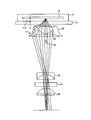
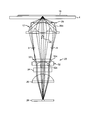
- FIG. 3 is a longitudinal sectional view showing a schematic configuration of the scanning module 9 placed on the second stage 8.
- an objective lens 17 that collects fluorescence from the sample 16 set on the sample table 4 is arranged in the upper part of the scanning module 9 in the vicinity of the sample table (glass) 4. Yes.
- excitation light such as laser light emitted from the light source 18 and condensed by a lens group 19 composed of a plurality of lenses.
- the reflection mirror 20 that reflects the light beam so as to enter the objective lens 17 is disposed.
- the objective lens 17 is housed in a lens holder 21, and the lens holder 21 can be moved in the direction of the optical axis of the objective lens 17 by a drive unit 22 such as a stepping motor. Thus, the objective lens 17 can move in the optical axis direction together with the lens holder 21.
- a first lens 23 for converting fluorescence from the sample 16 collected by the objective lens 17 into parallel light in order from the reflection mirror 20 side An excitation light cutting wavelength filter 24, a second lens 25 for condensing the fluorescence that has passed through the wavelength filter 24, and a pinhole 26 for cutting off the stray light of the fluorescence that has passed through the second lens 25 are disposed. Further, a detector 27 that detects fluorescence that has passed through the pinhole 26 is disposed below the pinhole 26 on the optical axis of the objective lens 17.
- the first lens 23 constitutes the conversion lens in the claims.
- the excitation light emitted from the light source 18 is focused by the lens group 19, then reflected by the reflection mirror 20, passes through the objective lens 17 and the sample stage 4, and the lower surface of the sample 16. Focused on one point.
- the length of the reflection mirror 20 in the longitudinal direction (direction perpendicular to the optical axis of the lens group 19) is short, the width in the direction perpendicular to the longitudinal direction is narrow, and the excitation light from the light source 18 is the objective light. Only the vicinity of the optical axis of the lens 17 (excitation light transmitting portion) passes therethrough.
- the light source 18, the lens group 19, and the reflection mirror 20 constitute the light source unit in the claims.
- the fluorescence is isotropically emitted from the portion of the sample 16 irradiated with the excitation light to the surroundings.
- the component of the emitted fluorescent light that has passed through the sample stage 4 made of glass and entered the objective lens 17 passes through the objective lens 17, the first lens 23, the wavelength filter 24, the second lens 25, and the pinhole 26. Passed and detected by detector 27.
- the detection signal from the detector 27 is sent to the PC 5 after being subjected to processing such as AD conversion by a built-in AD converter (not shown) or the like. In this way, the fluorescence intensity distribution at each measurement point on the sample 16 is recorded in the internal memory or the like.
- the fluorescence that has passed through the objective lens 17 becomes focused light and is guided in the direction of the first lens 23. Then, the light is refracted by the first lens 23 so as to be substantially parallel to the optical axis.
- the second lens 25 condenses the fluorescence.
- the pinhole 26 is arrange
- the excitation light cutting wavelength filter 24 is disposed, for example, in a rotating folder (not shown) or the like, and can be replaced with a filter of another wavelength according to the wavelength of the excitation light.
- FIG. 4 shows a perspective view of the objective lens 17.
- FIG. 4A is a perspective view seen from the reflection mirror 20 side.
- FIG. 4B is a perspective view seen from the sample table 4 side.
- FIG. 5 is a longitudinal sectional view of the objective lens 17.
- the objective lens 17 has a shape like an ashtray.
- the central portion including the optical axis includes an upper convex surface 28a and a lower convex surface 28b protruding in a spherical shape along the optical axis, and has a function of a normal convex lens (light is deflected only by refraction). 28.
- the fluorescence a having a small emission angle passes through the convex lens portion 28 and is condensed toward the detector 27.
- the periphery of the convex lens portion 28 in the objective lens 17 is a truncated cone-shaped cylindrical body 29 that opens downward. Then, of the fluorescence emitted from the sample 16, the fluorescence b having a large radiation angle that does not enter the convex lens portion 28 enters the cylindrical body 29 from the upper end surface 29 a of the cylindrical body 29, and the cylindrical body The light is totally reflected by the side surface 29b of 29, deflected toward the optical axis, and emitted from the lower end surface 29c of the cylindrical body 29 toward the detector 27.
- the convex lens portion 28 constitutes the refracting portion in the claims, and the cylindrical body 29 constitutes the total reflection portion.
- the lens element itself can be formed more compactly than the objective lens of the present fluorescence detection apparatus 1 can be achieved by realizing the NA equivalent to the objective lens 17 with a normal convex lens.
- the fluorescence condensed through the objective lens 17 is made into a state close to parallel light by the first lens 23 and is incident on the wavelength filter 24.
- the diameter of the fluorescent beam becomes large, leading to an increase in the size of the optical element below the first lens 23.
- the objective lens 17 having the convex lens portion 28 in the central portion and the frustoconical cylindrical body 29 around the convex lens portion 28 as described above the first lens 23, the wavelength filter 24, and Each optical element of the second lens 25 can be reduced in size, and the scanning module 9 can be reduced in size and weight.
- the first lens 23 for making the fluorescent light collected through the objective lens 17 incident on the wavelength filter 24 in a state close to parallel light is constituted by a normal concave lens 30 having only one curved surface.
- a ray diagram of fluorescence emitted from the sample 16 and passing from the objective lens 17 to the second lens 25 is as shown in FIG.
- the position of the objective lens 17 is set by the drive unit 22 so as to focus on the position of the sample 16 (the gel support or the transfer support) placed directly on the sample table (glass) 4.
- the light of the objective lens 17 is condensed so that the light passing through the convex lens portion 28 of the objective lens 17 and the light passing through the cylindrical body 29 are condensed at substantially the same position (position of the hole of the pinhole 26). Assume that the shape is optimized.
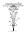
- the gel support as the sample 16 is sealed in the two-dimensional electrophoresis substrate 31 as shown in FIG.
- the distance from the objective lens 17 to the sample 16 is greater than the enclosed sample 16 in the two-dimensional electrophoresis substrate 31.
- the lower portion 31a is longer than the case of FIG. 6 by the thickness t. Therefore, even if the position of the objective lens 17 is set so as to focus on the position of the encapsulated sample 16 in the two-dimensional electrophoresis substrate 31, the light passing through the convex lens portion 28 of the objective lens 17 and the cylindrical body 29.
- the light passing through the pin hole 26 is not condensed at the position of the pin hole 26.
- the incident angle of the incident light to the wavelength filter 24 is not parallel to the optical axis, and the stray light cutting performance is deteriorated.
- FIG. 8 shows a perspective view of the first lens 23.
- FIG. 8A is a perspective view seen from the wavelength filter 24 side.
- FIG. 8B is a perspective view seen from the reflection mirror 20 side.
- FIG. 9 is a longitudinal sectional view of the first lens 23.
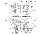
- FIG. 9A includes a ray diagram of fluorescence when the sample 16 is placed directly on the sample stage 4 (hereinafter referred to as “first case”).
- FIG. 9B shows a fluorescent ray diagram when the sample 16 is enclosed in the two-dimensional electrophoresis substrate 31 and placed on the sample table 4 (hereinafter referred to as “second case”). Contains.
- the first lens 23 includes a concave lens portion 32 in which a concave curved surface 32c is formed on a plane 32a of two planes 32a and 32b facing each other, and two planes facing each other.
- the fluorescence a that has passed through the convex lens portion 28 of the objective lens 17 is a convex lens in both the first case and the second case. It passes through a flat surface 33 b in the portion 33 and a concave curved surface 32 c in the concave lens portion 32.
- the fluorescence b totally reflected by the cylindrical body 29 of the objective lens 17 is as shown in FIG. 9A in the first case.
- the convex lens portion 33 passes through the convex curved surface 33c and the concave lens portion 32 passes through the concave curved surface 32c.
- the light passes through a flat surface 33 b in the convex lens portion 33 and a concave curved surface 32 c in the concave lens portion 32.
- the first lens 23 may be formed by simply laminating the concave lens portion 32 and the convex lens portion 33 with each other, or may be formed by bonding the concave lens portion 32 and the convex lens portion 33. . Or you may comprise the concave lens part 32 and the convex lens part 33 integrally.
- the measurement target in the present embodiment is a fluorescent portion in a spot of excitation light that is emitted from the light source 18, converged by the lens group 19, reflected by the reflection mirror 20, and collected at one point on the lower surface of the sample 16. It is. Therefore, it can be regarded as a point light source.
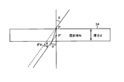
- a point light source as shown in FIG. 10, the light incident on the light transmission plate 34 at an incident angle ⁇ ′ from the point light source P on the surface of the light transmission plate 34 having a refractive index N and a thickness d is Then, the light is refracted on the back surface of the light transmission plate 34 and is emitted at the emission angle ⁇ .
- the light emitted from the back surface of the light transmission plate 34 seems to have been emitted using the point P ′ in the light transmission plate 34 as a light source.
- a deviation of the distance ⁇ occurs between the point light source P and the apparent light source P ′.
- FIG. 11 shows the inside of the cylindrical body 29 from the point Q on the upper end surface 29a of the cylindrical body 29 among the fluorescent light b having a large value of (d ⁇ ) that is totally reflected by the cylindrical body 29 of the objective lens 17. Shows the optical path of the light incident on.
- the optical path L1 is the optical path of the “first case”
- the optical path L2 is the optical path of the “second case”.
- the deviation ⁇ is larger in the “second case” than in the “first case”.
- the objective lens 17 is moved to the sample 16 side by the thickness t of the lower portion 31a of the two-dimensional electrophoresis substrate 31 in the optical axis direction by the drive unit 22.
- the influence of the deviation distance ⁇ on the fluorescence a passing through the 17 convex lens portions 28 is canceled, but the influence on the fluorescence b totally reflected by the cylindrical body 29 remains.
- the apparent light source P′1 of the light incident on the point Q in the “first case” is more than the apparent light source P′2 of the light incident on the point Q in the “second case”. Is far from the upper end of the objective lens 17.
- the incident angle ⁇ and the refraction angle ⁇ at the point Q are larger in the “second case” than in the “first case” ( ⁇ 2> ⁇ 1, ⁇ 2> ⁇ 1), and the cylindrical body 29
- the reflection angle ⁇ at the side surface 29b is small ( ⁇ 2 ⁇ 1).
- the incident angle of the incident light on the wavelength filter 24 is not parallel to the optical axis, and is not condensed at the position of the pinhole 26.
- the total reflected light L2 on the side surface 29b in the “second case” is incident on the wavelength filter 24 in parallel with the light that has passed through the convex lens portion 28.
- the reflected light L1 on the side surface 29b in the “first case” is also incident on the wavelength filter 24 in parallel with the light that has passed through the convex lens portion 28.
- the fluorescence a refracted by the convex lens portion 28 in the objective lens 17 is The fluorescent light b incident on the first region passing through the region A1 of the flat surface 33b and the region B1 of the concave curved surface 32c in the one lens 23 and totally reflected by the side surface 29b is the region A2 of the flat surface 33b and the concave curved surface in the first lens 23.
- the angle of the reflecting surface (side surface) 29b of the objective lens 17 and the curvature of the surface through which the totally reflected light passes, so as to satisfy the condition 1 that is incident on the second region passing through the region B2 of 32c, and the first lens 23 Set the shape and.
- the convex lens portion 33 of the first lens 23 simply functions in the same manner as a glass plate. Accordingly, the light rays of the fluorescent light a and b incident on the flat surface 33b of the convex lens portion 33 while being condensed are refracted and become parallel to the optical axis, and are diverged and become more parallel to each other (the spread angle is 0 degree). Near). The light beams of the fluorescent light a and b further pass through the concave curved surface 32c of the concave lens portion 32, so that they are substantially parallel to the optical axis (the spread angle is substantially 0 degree). That is, the fluorescence b incident on the first lens 23 undergoes a diverging action as a whole.
- the convergent light totally reflected by the cylindrical body 29 of the objective lens 17 is incident on the second region of the first lens 23, first, the light parallel to the optical axis.
- the inclination angle with respect to the optical axis of the incident surface (A2 of the flat surface 33b) and the inclination angle of the output surface (B2 of the concave curved surface 32c) with respect to the optical axis are set so as to be refracted into the second region.
- the sum of the curvature of the incident surface (A2 of the flat surface 33b) and the curvature of the outgoing surface (B2 of the concave curved surface 32c) in the second region diverges incident light.
- the fluorescent light a and b incident on the first lens 23 are converted into light. It is converted into light substantially parallel to the axis.
- the fluorescence b totally reflected by the side surface 29b of the objective lens 17 out of the fluorescence from the sample 16 is temporarily After the light is condensed, the reflecting surface (side surface) 29b of the objective lens 17 is satisfied so as to satisfy the condition 2 that is incident on the third region passing through the region A3 of the convex curved surface 33c and the region B3 of the concave curved surface 32c. And the curvature of the surface through which the totally reflected light passes, and the shape of the first lens 23 are set.
- the fluorescence a refracted by the convex lens portion 28 in the objective lens 17 is hardly affected by a change in the distance between the objective lens 17 and the sample 16, as in the “second case”,
- the first lens 23 is incident on the first region passing through the region A1 of the flat surface 33b and the region B1 of the concave curved surface 32c.
- the convex lens portion 33 of the first lens 23 functions in the same manner as the convex lens. Therefore, the fluorescent b beams incident on the convex curved surface 33c of the convex lens portion 33 while diverging are refracted and become parallel to the optical axis, and are condensed and more parallel to each other (the spread angle is closer to 0 degree). ) Being. Each light beam of the fluorescent light b further passes through the concave curved surface 32c of the concave lens portion 32 and becomes substantially parallel to the optical axis (the spread angle is substantially 0 degree). That is, the fluorescence b incident on the first lens 23 is subjected to a condensing action as a whole.
- the sum of the curvature of the incident surface (A3 of the convex curved surface 33c) and the curvature of the outgoing surface (B3 of the concave curved surface 32c) in the third region focuses the incident light. It is set so that the curvature is the desired one.
- the curvature of A3 of the convex curved surface 33c is “curvature for focusing incident light”
- the curvature of B3 of the concave curved surface 32c is “curvature for diverging incident light”.
- the curvature is made smaller than the curvature of A3 of the convex curved surface 33c, and the total curvature is set to a curvature for focusing the incident light.
- the fluorescence b incident on the first lens 23 becomes light It is converted into light substantially parallel to the axis.
- the curvature of the entrance surface and the exit surface in the first to third regions of the first lens 23 is set to “0”, that is, when each region is constituted by a part of a triangular prism, Although the spread angle of incident light can be improved to some extent by the angle formed by the incident surface and the exit surface, the spread angle cannot be controlled to substantially 0 degrees. Therefore, in the present embodiment, as described above, the curvature of at least one of the entrance surface and the exit surface in each region is set to a curvature other than “0”, and the total curvature is incident. The curvature is to converge or diverge the light.
- the shape including the inclination angle and the curvature with respect to the regions B1 to B3 of the concave curved surface 32c is set so as to satisfy the above conditions 1 and 2. Therefore, the “first case” in which the sample 16 is directly placed on the sample stage 4 and the “second case” in which the sample 16 is enclosed in the two-dimensional electrophoresis substrate 31 and placed on the sample stage 4.
- the light beams of the fluorescent light a refracted by the convex lens portion 28 of the objective lens 17 and the fluorescent light b totally reflected by the side surface 29b are approximately aligned with the optical axis when emitted from the first lens 23. Can be parallel. Therefore, the stray light can be accurately cut by the wavelength filter 24.
- the inclination angle and the curvature are obtained by using both the entrance surface and the exit surface.
- an appropriate value is set. That is, the “inclination angle” and “curvature” in each region are important for the total value of the entrance surface and the exit surface. Therefore, first, the “inclination angle” and the “curvature” are set to be different between the incident surface A2 of the second region and the incident surface A3 of the third region. Second, the “inclination angle” and the “curvature” are set to be different between the exit surface B2 of the second region and the exit surface B3 of the third region. By doing so, both the entrance surface and the exit surface can be used in both regions, and the degree of freedom in designing the “inclination angle” and “curvature” can be increased.
- the fluorescence condensed by the objective lens 17 is made substantially parallel light.
- a detection optical system including a first lens 23, a wavelength filter 24 for cutting excitation light, a second lens 25 for collecting fluorescence, a pinhole 26 for cutting stray light, and a detector 27 for detecting fluorescence is integrated. It is stored.
- the objective lens 17 is configured to have a convex lens portion 28 at the central portion and a truncated cone-shaped cylindrical body 29 around the convex lens portion 28. Therefore, of the fluorescence emitted from the sample 16, the fluorescence b having a large emission angle that does not enter the convex lens portion 28 can be totally reflected by the side surface 29 b of the cylindrical body 29 and condensed. Light with a large radiation angle that cannot be collected by a convex lens can also be collected. As a result, the concentration ratio of the fluorescence can be increased, and a decrease in S / N due to the presence of fluorescence that is blocked by the prism 20 disposed on the optical axis of the objective lens 17 and is not detected by the detector 27 is prevented. Thus, a highly sensitive fluorescence information reader can be realized.
- the scanning module 9 is moved. There is no need to move the concave mirror in the same direction in synchronization with the. For this reason, the scanning mechanism for the two-dimensional scanning is not complicated.
- the objective lens 17 can be made smaller than the case where the fluorescence b having a large radiation angle is collected by a normal convex lens having a high NA. Further, since the objective lens 17 condenses the fluorescence from the sample 16 and enters the first lens 23, the first lens 23, the wavelength filter 24, and the second that are installed on the optical path that guides the fluorescence to the detector 27. Optical elements such as the lens 25 can also be reduced in size.
- the scanning module 9 in which the light irradiation optical system and the detection optical system are mounted.
- Weight can be reduced. Accordingly, the configuration of the scanning mechanism can be simplified, the weight can be reduced, and the scanning module 9 can be scanned at high speed. Therefore, it is possible to detect a two-dimensional fluorescence distribution at a plurality of different positions in the sample 16 at high speed.
- the first lens 23 is configured in a shape having a concave lens portion 32 in which a concave curved surface 32c is formed at the center of a flat surface 32a and a convex lens portion 33 in which a convex curved surface 33c is formed around a flat surface 33b.
- region are provided toward the outer side from the center part.
- the first region and the second region are regions passing through the flat surface 33b of the convex lens portion 33 and the concave curved surface 32c of the concave lens portion 32, and the incident light beam is made parallel by the optical axis and diverges as a total. It is an area to be made.
- the third region is a region that passes through the convex curved surface 33c of the convex lens portion 33 and the concave curved surface 32c of the concave lens portion 32, and is a region that collimates the incident light beam by the optical axis and collects it as a total. is there.
- the optical path L2 after total reflection by the objective lens 17 is on the optical axis side (center).
- the fluorescence b totally reflected by the objective lens 17 is caused to enter the second region of the first lens 23.
- the second region is a region for making incident light rays parallel to the optical axis and diverging as a total. Therefore, if the light totally reflected by the objective lens 17 is collected, the light beams of the fluorescence b emitted from the second region of the first lens 23 are substantially parallel to each other and with respect to the optical axis. But they are almost parallel.
- the fluorescence b totally reflected by the objective lens 17 is made incident on the third region of the first lens 23.
- the third region is a region that collimates incident light rays by the optical axis and collects them as a total. Therefore, if light that is totally reflected by the objective lens 17 and incident on the first lens 23 is diverged, the light beams of the fluorescence b emitted from the third region of the first lens 23 are substantially parallel to each other. In addition, it is substantially parallel to the optical axis.
- the light totally reflected by the objective lens 17 is made to enter the first lens 23 as shown in FIG. It may be once condensed before being incident.
- the light totally reflected by the objective lens 17 can be incident on the second region of the first lens 23 while being condensed, and the “ In the “first case”, the reflection surface of the objective lens 17 is arranged so that the light totally reflected by the objective lens 17 can be incident on the third region of the first lens 23 while being diverged and then diverged. (Surface)
- the angle of 29b, the curvature of the surface through which the totally reflected light passes, and the shape including the inclination angle and curvature of the convex curved surface 33c and the concave curved surface 32c of the first lens 23 are set.
- the sample 16 is placed directly on the sample stage 4 and a case where the sample 16 is enclosed in the two-dimensional electrophoresis substrate 31 and placed on the sample stage 4.
- the fluorescence b totally reflected by the side surface 29b of the objective lens 17 is reflected on the optical axis when emitted from the first lens 23. It can be made substantially parallel. Therefore, the stray light can be accurately cut by the wavelength filter 24.
- the fluorescent light a refracted by the convex lens portion 28 of the objective lens 17 and the fluorescent light b totally reflected by the side surface 29 b can be condensed at the position of the pinhole 26 via the first lens 23. . Therefore, even when the distance from the objective lens 17 to the apparent light source P ′ is different, it is possible to detect the fluorescence with the stable detector 27 while keeping the light collection state constant.
- the fluorescence emitted from the sample 16 using the objective lens 17 having the convex lens portion 28 in the central portion and the cylindrical body 29 having the truncated cone shape around the convex lens portion 28 when condensing fluorescence with a large radiation angle that cannot be collected by a normal convex lens to increase the concentration ratio of the fluorescence, the distance from the objective lens 17 to the apparent light source P ′ is different. However, the fluorescence can be detected accurately and stably.
- the second region and the third region are the regions where the light totally reflected by the cylindrical body 29 of the objective lens 17 is incident on the first lens 23. And two areas.
- the present invention is not limited to two regions, and three or more regions may be provided according to the number of changes in the distance between the objective lens 17 and the sample 16.
Landscapes
- Physics & Mathematics (AREA)
- General Physics & Mathematics (AREA)
- Health & Medical Sciences (AREA)
- Optics & Photonics (AREA)
- Chemical & Material Sciences (AREA)
- Analytical Chemistry (AREA)
- Life Sciences & Earth Sciences (AREA)
- Biochemistry (AREA)
- General Health & Medical Sciences (AREA)
- Immunology (AREA)
- Pathology (AREA)
- Nuclear Medicine, Radiotherapy & Molecular Imaging (AREA)
- Engineering & Computer Science (AREA)
- Biomedical Technology (AREA)
- Molecular Biology (AREA)
- Investigating, Analyzing Materials By Fluorescence Or Luminescence (AREA)
- Microscoopes, Condenser (AREA)
Abstract
Par la présente invention, même lorsque la distance à partir d'une lentille de focalisation à un échantillon varie de fluorescence, la distribution de la lumière provenant de l'échantillon peut être détectée avec une bonne précision. Une première lentille (23) servant à former de la lumière à partir d'une lentille de focalisation dans un faisceau parallèle est configurée à partir d'une partie de lentille concave (32) dans laquelle une surface concave (32c) est formée au centre d'une surface plate (32a), et une partie de lentille convexe (33) dans laquelle une surface convexe (33c) est formée sur la périphérie d'une surface plate (33b). Les première et seconde régions pour amener la lumière divergent à travers la surface plane (33b) et la surface concave (32c), et une troisième région pour focaliser la lumière à travers la surface convexe (33c) et la surface concave (32c) sont en outre prévus Lorsqu'un échantillon est scellé dans un substrat pour l'électrophorèse bidimensionnelle et monté sur un étage d'échantillon, l, la lumière qui est totalement réfléchie par une surface latérale de la lentille d'objectif est incidente sur la seconde région, et lorsque l'échantillon est monté directement sur l'étage d'échantillon, la lumière est incidente sur la troisième région. En conséquence, dans tous les cas, les faisceaux lumineux de la lumière (d) émise à partir de la première lentille (23) un sont sensiblement parallèles l'un à l'autre et également sensiblement parallèles à l'axe optique.
Priority Applications (2)
| Application Number | Priority Date | Filing Date | Title |
|---|---|---|---|
| EP13763578.5A EP2829901B1 (fr) | 2012-03-21 | 2013-02-20 | Unité optique, dispositif de détection de fluorescence, et procédé de détection de fluorescence |
| US14/378,674 US9006687B2 (en) | 2012-03-21 | 2013-02-20 | Optical unit, fluorescence detection device, and fluorescence detection method |
Applications Claiming Priority (2)
| Application Number | Priority Date | Filing Date | Title |
|---|---|---|---|
| JP2012-063445 | 2012-03-21 | ||
| JP2012063445A JP5497088B2 (ja) | 2012-03-21 | 2012-03-21 | 光学ユニット、蛍光検出装置、および、蛍光検出方法 |
Publications (1)
| Publication Number | Publication Date |
|---|---|
| WO2013140924A1 true WO2013140924A1 (fr) | 2013-09-26 |
Family
ID=49222389
Family Applications (1)
| Application Number | Title | Priority Date | Filing Date |
|---|---|---|---|
| PCT/JP2013/054144 Ceased WO2013140924A1 (fr) | 2012-03-21 | 2013-02-20 | Unité optique, dispositif de détection de fluorescence, et procédé de détection de fluorescence |
Country Status (4)
| Country | Link |
|---|---|
| US (1) | US9006687B2 (fr) |
| EP (1) | EP2829901B1 (fr) |
| JP (1) | JP5497088B2 (fr) |
| WO (1) | WO2013140924A1 (fr) |
Families Citing this family (8)
| Publication number | Priority date | Publication date | Assignee | Title |
|---|---|---|---|---|
| JP5575159B2 (ja) * | 2012-01-26 | 2014-08-20 | シャープ株式会社 | 蛍光情報読み取り装置および蛍光情報読み取り方法 |
| BR112015028910A2 (pt) * | 2013-07-09 | 2017-07-25 | Halliburton Energy Services Inc | elementos computacionais integrados com filtros espectrais lateralmente distribuídos |
| JP2017156694A (ja) * | 2016-03-04 | 2017-09-07 | 株式会社フォブ | 光学顕微鏡、及び観察方法 |
| CN106949383B (zh) * | 2017-04-01 | 2023-03-21 | 安徽仁和光电科技有限公司 | 一种利用激光诱导荧光的照明系统 |
| DE102019106267A1 (de) | 2019-03-12 | 2020-09-17 | Valeo Schalter Und Sensoren Gmbh | Lichtsignalumlenkeinrichtung für ein optisches Messsystem zur Erfassung von Objekten, Messsystem und Verfahren zum Betreiben einer Lichtsignalumlenkeinrichtung |
| JP7439438B2 (ja) * | 2019-09-30 | 2024-02-28 | ソニーグループ株式会社 | 生体粒子分析用マイクロチップ、生体粒子分析装置、微小粒子分析用マイクロチップ、及び微小粒子分析装置 |
| CN114063375B (zh) * | 2020-08-10 | 2024-01-23 | 成都极米科技股份有限公司 | 一种光源系统 |
| KR20230046616A (ko) * | 2021-09-30 | 2023-04-06 | 주식회사 씨젠 | Tir 렌즈를 포함하는 타깃 분석물 검출장치 |
Citations (5)
| Publication number | Priority date | Publication date | Assignee | Title |
|---|---|---|---|---|
| JPH0783900A (ja) * | 1993-06-28 | 1995-03-31 | Canon Inc | 流体検査装置 |
| JPH103134A (ja) | 1996-06-18 | 1998-01-06 | Fuji Photo Film Co Ltd | 画像読み取り装置 |
| JP2000162126A (ja) | 1998-11-25 | 2000-06-16 | Fuji Photo Film Co Ltd | 画像情報読取装置 |
| JP2001074657A (ja) * | 1999-09-09 | 2001-03-23 | Fuji Photo Film Co Ltd | 光計測方法および装置 |
| JP2007248063A (ja) * | 2006-03-13 | 2007-09-27 | Hitachi Ltd | 光検出装置 |
Family Cites Families (4)
| Publication number | Priority date | Publication date | Assignee | Title |
|---|---|---|---|---|
| US2224178A (en) * | 1940-05-08 | 1940-12-10 | Ralph E Bitner | Catadioptrical lens system |
| US6362923B1 (en) * | 2000-03-10 | 2002-03-26 | Kla-Tencor | Lens for microscopic inspection |
| JP2002207009A (ja) * | 2001-01-11 | 2002-07-26 | Nikon Corp | 走査型蛍光測定装置 |
| US7798677B2 (en) * | 2008-04-29 | 2010-09-21 | Himax Display, Inc. | Illumination unit for projection systems |
-
2012
- 2012-03-21 JP JP2012063445A patent/JP5497088B2/ja not_active Expired - Fee Related
-
2013
- 2013-02-20 US US14/378,674 patent/US9006687B2/en not_active Expired - Fee Related
- 2013-02-20 WO PCT/JP2013/054144 patent/WO2013140924A1/fr not_active Ceased
- 2013-02-20 EP EP13763578.5A patent/EP2829901B1/fr not_active Not-in-force
Patent Citations (5)
| Publication number | Priority date | Publication date | Assignee | Title |
|---|---|---|---|---|
| JPH0783900A (ja) * | 1993-06-28 | 1995-03-31 | Canon Inc | 流体検査装置 |
| JPH103134A (ja) | 1996-06-18 | 1998-01-06 | Fuji Photo Film Co Ltd | 画像読み取り装置 |
| JP2000162126A (ja) | 1998-11-25 | 2000-06-16 | Fuji Photo Film Co Ltd | 画像情報読取装置 |
| JP2001074657A (ja) * | 1999-09-09 | 2001-03-23 | Fuji Photo Film Co Ltd | 光計測方法および装置 |
| JP2007248063A (ja) * | 2006-03-13 | 2007-09-27 | Hitachi Ltd | 光検出装置 |
Non-Patent Citations (1)
| Title |
|---|
| See also references of EP2829901A4 |
Also Published As
| Publication number | Publication date |
|---|---|
| EP2829901A4 (fr) | 2015-03-25 |
| US20150028226A1 (en) | 2015-01-29 |
| EP2829901A1 (fr) | 2015-01-28 |
| US9006687B2 (en) | 2015-04-14 |
| EP2829901B1 (fr) | 2016-12-14 |
| JP5497088B2 (ja) | 2014-05-21 |
| JP2013195760A (ja) | 2013-09-30 |
Similar Documents
| Publication | Publication Date | Title |
|---|---|---|
| JP5497088B2 (ja) | 光学ユニット、蛍光検出装置、および、蛍光検出方法 | |
| US6355934B1 (en) | Imaging system for an optical scanner | |
| US8686376B2 (en) | Microarray characterization system and method | |
| JP4945025B2 (ja) | 軸方向高解像度を有する走査型顕微鏡方法 | |
| JP5575159B2 (ja) | 蛍光情報読み取り装置および蛍光情報読み取り方法 | |
| JP6058977B2 (ja) | 蛍光検出装置 | |
| US7016087B2 (en) | Photon efficient scanner | |
| CN101868752B (zh) | 用于利用线束照射样本的光学照射装置 | |
| CN100338445C (zh) | 光学部件、使用该部件的光检测装置和方法、及分析方法 | |
| CN111788473B (zh) | 用于检测结合亲和力的装置 | |
| JP2007248063A (ja) | 光検出装置 | |
| US7728980B2 (en) | Optical unit | |
| JP3846397B2 (ja) | 共焦点光学系を備えたバイオチップ | |
| JP2007132792A (ja) | 光計測装置と試料との光結合系 | |
| WO2014064993A1 (fr) | Élément lentille | |
| JP5745492B2 (ja) | 光検出装置 | |
| JP2009002774A (ja) | 生体物質検出装置 | |
| KR20140021620A (ko) | 콤팩트한 무 라벨 이미징 시스템 | |
| JP5899038B2 (ja) | 蛍光検出装置および蛍光検出方法 | |
| JP2010117240A (ja) | 蛍光検出装置 | |
| JP2014052252A (ja) | 蛍光検出装置 | |
| WO2012074472A1 (fr) | Scanneur de détection de luminescence et procédé servant à détecter la luminescence | |
| JP2014071059A (ja) | 光検出装置 | |
| WO2013191040A1 (fr) | Dispositif de détection de fluorescence |
Legal Events
| Date | Code | Title | Description |
|---|---|---|---|
| 121 | Ep: the epo has been informed by wipo that ep was designated in this application |
Ref document number: 13763578 Country of ref document: EP Kind code of ref document: A1 |
|
| WWE | Wipo information: entry into national phase |
Ref document number: 14378674 Country of ref document: US |
|
| REEP | Request for entry into the european phase |
Ref document number: 2013763578 Country of ref document: EP |
|
| WWE | Wipo information: entry into national phase |
Ref document number: 2013763578 Country of ref document: EP |
|
| NENP | Non-entry into the national phase |
Ref country code: DE |