WO2013140948A1 - Dispositif de retenue pour un roulement à rouleaux, et structure de roulement à rouleaux - Google Patents
Dispositif de retenue pour un roulement à rouleaux, et structure de roulement à rouleaux Download PDFInfo
- Publication number
- WO2013140948A1 WO2013140948A1 PCT/JP2013/054687 JP2013054687W WO2013140948A1 WO 2013140948 A1 WO2013140948 A1 WO 2013140948A1 JP 2013054687 W JP2013054687 W JP 2013054687W WO 2013140948 A1 WO2013140948 A1 WO 2013140948A1
- Authority
- WO
- WIPO (PCT)
- Prior art keywords
- roller
- diameter side
- cage
- outer diameter
- inner diameter
- Prior art date
- Legal status (The legal status is an assumption and is not a legal conclusion. Google has not performed a legal analysis and makes no representation as to the accuracy of the status listed.)
- Ceased
Links
Images


Classifications
-
- F—MECHANICAL ENGINEERING; LIGHTING; HEATING; WEAPONS; BLASTING
- F16—ENGINEERING ELEMENTS AND UNITS; GENERAL MEASURES FOR PRODUCING AND MAINTAINING EFFECTIVE FUNCTIONING OF MACHINES OR INSTALLATIONS; THERMAL INSULATION IN GENERAL
- F16C—SHAFTS; FLEXIBLE SHAFTS; ELEMENTS OR CRANKSHAFT MECHANISMS; ROTARY BODIES OTHER THAN GEARING ELEMENTS; BEARINGS
- F16C33/00—Parts of bearings; Special methods for making bearings or parts thereof
- F16C33/30—Parts of ball or roller bearings
- F16C33/46—Cages for rollers or needles
- F16C33/4605—Details of interaction of cage and race, e.g. retention or centring
-
- F—MECHANICAL ENGINEERING; LIGHTING; HEATING; WEAPONS; BLASTING
- F16—ENGINEERING ELEMENTS AND UNITS; GENERAL MEASURES FOR PRODUCING AND MAINTAINING EFFECTIVE FUNCTIONING OF MACHINES OR INSTALLATIONS; THERMAL INSULATION IN GENERAL
- F16C—SHAFTS; FLEXIBLE SHAFTS; ELEMENTS OR CRANKSHAFT MECHANISMS; ROTARY BODIES OTHER THAN GEARING ELEMENTS; BEARINGS
- F16C33/00—Parts of bearings; Special methods for making bearings or parts thereof
- F16C33/30—Parts of ball or roller bearings
- F16C33/46—Cages for rollers or needles
- F16C33/467—Details of individual pockets, e.g. shape or roller retaining means
- F16C33/4676—Details of individual pockets, e.g. shape or roller retaining means of the stays separating adjacent cage pockets, e.g. guide means for the bearing-surface of the rollers
-
- F—MECHANICAL ENGINEERING; LIGHTING; HEATING; WEAPONS; BLASTING
- F16—ENGINEERING ELEMENTS AND UNITS; GENERAL MEASURES FOR PRODUCING AND MAINTAINING EFFECTIVE FUNCTIONING OF MACHINES OR INSTALLATIONS; THERMAL INSULATION IN GENERAL
- F16C—SHAFTS; FLEXIBLE SHAFTS; ELEMENTS OR CRANKSHAFT MECHANISMS; ROTARY BODIES OTHER THAN GEARING ELEMENTS; BEARINGS
- F16C19/00—Bearings with rolling contact, for exclusively rotary movement
- F16C19/22—Bearings with rolling contact, for exclusively rotary movement with bearing rollers essentially of the same size in one or more circular rows, e.g. needle bearings
- F16C19/24—Bearings with rolling contact, for exclusively rotary movement with bearing rollers essentially of the same size in one or more circular rows, e.g. needle bearings for radial load mainly
- F16C19/26—Bearings with rolling contact, for exclusively rotary movement with bearing rollers essentially of the same size in one or more circular rows, e.g. needle bearings for radial load mainly with a single row of rollers
-
- F—MECHANICAL ENGINEERING; LIGHTING; HEATING; WEAPONS; BLASTING
- F16—ENGINEERING ELEMENTS AND UNITS; GENERAL MEASURES FOR PRODUCING AND MAINTAINING EFFECTIVE FUNCTIONING OF MACHINES OR INSTALLATIONS; THERMAL INSULATION IN GENERAL
- F16C—SHAFTS; FLEXIBLE SHAFTS; ELEMENTS OR CRANKSHAFT MECHANISMS; ROTARY BODIES OTHER THAN GEARING ELEMENTS; BEARINGS
- F16C33/00—Parts of bearings; Special methods for making bearings or parts thereof
- F16C33/30—Parts of ball or roller bearings
- F16C33/46—Cages for rollers or needles
- F16C33/4617—Massive or moulded cages having cage pockets surrounding the rollers, e.g. machined window cages
- F16C33/4623—Massive or moulded cages having cage pockets surrounding the rollers, e.g. machined window cages formed as one-piece cages, i.e. monoblock cages
-
- F—MECHANICAL ENGINEERING; LIGHTING; HEATING; WEAPONS; BLASTING
- F16—ENGINEERING ELEMENTS AND UNITS; GENERAL MEASURES FOR PRODUCING AND MAINTAINING EFFECTIVE FUNCTIONING OF MACHINES OR INSTALLATIONS; THERMAL INSULATION IN GENERAL
- F16C—SHAFTS; FLEXIBLE SHAFTS; ELEMENTS OR CRANKSHAFT MECHANISMS; ROTARY BODIES OTHER THAN GEARING ELEMENTS; BEARINGS
- F16C33/00—Parts of bearings; Special methods for making bearings or parts thereof
- F16C33/30—Parts of ball or roller bearings
- F16C33/46—Cages for rollers or needles
- F16C33/467—Details of individual pockets, e.g. shape or roller retaining means
-
- F—MECHANICAL ENGINEERING; LIGHTING; HEATING; WEAPONS; BLASTING
- F16—ENGINEERING ELEMENTS AND UNITS; GENERAL MEASURES FOR PRODUCING AND MAINTAINING EFFECTIVE FUNCTIONING OF MACHINES OR INSTALLATIONS; THERMAL INSULATION IN GENERAL
- F16C—SHAFTS; FLEXIBLE SHAFTS; ELEMENTS OR CRANKSHAFT MECHANISMS; ROTARY BODIES OTHER THAN GEARING ELEMENTS; BEARINGS
- F16C19/00—Bearings with rolling contact, for exclusively rotary movement
- F16C19/22—Bearings with rolling contact, for exclusively rotary movement with bearing rollers essentially of the same size in one or more circular rows, e.g. needle bearings
- F16C19/44—Needle bearings
- F16C19/46—Needle bearings with one row or needles
- F16C19/463—Needle bearings with one row or needles consisting of needle rollers held in a cage, i.e. subunit without race rings
-
- F—MECHANICAL ENGINEERING; LIGHTING; HEATING; WEAPONS; BLASTING
- F16—ENGINEERING ELEMENTS AND UNITS; GENERAL MEASURES FOR PRODUCING AND MAINTAINING EFFECTIVE FUNCTIONING OF MACHINES OR INSTALLATIONS; THERMAL INSULATION IN GENERAL
- F16C—SHAFTS; FLEXIBLE SHAFTS; ELEMENTS OR CRANKSHAFT MECHANISMS; ROTARY BODIES OTHER THAN GEARING ELEMENTS; BEARINGS
- F16C2300/00—Application independent of particular apparatuses
- F16C2300/02—General use or purpose, i.e. no use, purpose, special adaptation or modification indicated or a wide variety of uses mentioned
Definitions
- the present invention relates to a cage having a plurality of pockets for accommodating rollers.
- Roller bearings such as cylindrical rollers and needle rollers include a plurality of rollers that roll between the outer raceway surface and the inner raceway surface, and a cage that holds these rollers at equal intervals in the circumferential direction.
- a cage that is used for a roller with a cage and holds the roller in each pocket, if the molding die is forcibly removed from the pocket, there will be inconveniences such as a burr resulting in a change in the shape of the cage. .
- Patent Document 1 Japanese Patent Laid-Open No. 2000-145790
- Patent Document 1 relates to a needle roller with a cage, and forms a holding ridge for roller stopper extending in the axial direction on the wall surface of a pillar portion of the cage facing the pocket.
- the protrusions are arranged on the outer diameter side and the inner diameter side of the cage to prevent the rollers from falling off.
- the cross-sectional shape of the distal end portion of the outer diameter side holding protrusion arranged on the outer diameter side of the cage is rounded into an arc shape, and the radius of the arc is set to 0 of the protruding height of the outer diameter side holding protrusion. It is larger than 5 times and smaller than 1.5 times.
- both easy removal and a roller drop-off effect can be realized. Further, when assembling the roller with cage, the roller can be easily inserted into the pocket from the outer diameter side.
- the present inventor has found that there is a point to be further improved in the conventional cage.
- the smaller the inclination angle of the inner diameter side inclined surface of the outer diameter side holding ridge the more the rollers are sandwiched between the pair of outer diameter side holding ridges facing each other through the pocket, and the rollers do not rotate smoothly. A possibility arises.
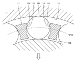
- FIG. 12 is a cross-sectional view showing a conventional roller with cage, and is an enlarged view of the roller accommodated in the pocket.
- the roller with cage provided in the annular space defined by the outer raceway surface 131 and the inner raceway surface 132, when the cage 111 moves eccentrically from the neutral position in the direction of the arrow, The rolling surface 121 comes into contact with the outer diameter side holding protrusion 115. And the roller 121 will be pinched
- the roller 121 is formed like a wedge between a pair of inner diameter side inclined surfaces 115i that are formed on the inner diameter side of the outer diameter side holding projection 115 and become thinner like a tapered surface toward the outer diameter side.
- the rotation of the roller 121 is obstructed, which may hinder smooth rotation.
- an object of the present invention is to provide a cage capable of solving the problem that a roller is caught by a holding projection for stopping a roller.
- a roller bearing retainer comprises a pair of ring portions and a plurality of column portions extending in the axial direction so as to connect the pair of ring portions and form a pocket for accommodating the rollers.
- the pillar part is provided on the outer diameter side of the wall surface of the pillar part facing the pocket and protrudes in the circumferential direction, and the outer diameter side protrusion part that restricts the movement of the roller to the outer diameter side, and the pillar part facing the pocket Provided on the inner diameter side of the wall surface of the roller and projecting in the circumferential direction, and having an inner diameter side protrusion that restricts the movement of the roller toward the inner diameter side, the outer diameter side from the pitch circle of the roller allowed by the outer diameter side protrusion
- the relationship between the allowable movement amount Lo to the inner diameter side and the allowable movement amount Li from the pitch circle of the roller allowed by the inner diameter side protrusion to the inner diameter side satisfies the relationship Lo> Li.
- the roller at the neutral position where the cage is concentric with the pitch circle of the roller, the roller does not contact both the outer diameter side protrusion and the inner diameter side protrusion. Since the inner diameter side allowable movement amount Li of the roller is smaller than the outer diameter side allowable movement amount Lo, when the cage deviates from the neutral position and moves eccentrically, the roller contacts the inner diameter side protrusion. As a result, contact between the roller and the outer diameter side protrusion is avoided. Therefore, the roller is not sandwiched between the pair of outer diameter side protrusions.
- the inner diameter side allowable movement amount Li of the roller is opposed to the distance from the pitch circle to the inner diameter side protrusion, the inclination angle between the wall surface of the column portion and the outer diameter side inclined surface of the inner diameter side protrusion, or 1 through the pocket. It is determined by the distance between the pair of inner diameter side protrusions. Specifically, the smaller the distance from the pitch circle to the inner diameter side protrusion, and the larger the inclination angle between the wall surface of the column portion and the outer diameter side inclined surface of the inner diameter side protrusion, the pair of inner diameter side protrusions. The smaller the distance between them, the smaller the inner diameter side allowable movement amount Li.
- the outer diameter side allowable movement amount Lo of the roller is the distance from the pitch circle to the outer diameter side protrusion, the inclination angle between the wall surface of the column portion and the inner diameter side inclined surface of the outer diameter side protrusion, and the pocket. It is determined by the distance between a pair of outer diameter side protrusions facing each other. Specifically, the larger the distance from the pitch circle to the outer diameter side protrusion, and the larger the inclination angle between the wall surface of the column and the inner diameter side inclined surface of the outer diameter side protrusion, the more the pair of outer diameter sides The smaller the distance between the protrusions, the smaller the outer diameter side allowable movement amount Lo.
- the cage is made of resin or metal.
- the cage is made of polyamide resin or iron-based metal.
- the inner diameter side inclined surface of the outer diameter side projection is relatively It is good to make it gentle slope.
- the outer diameter side inclined surface of the inner diameter side protrusion is relatively steep.
- the relationship between the distance Bo between the outer diameter side projections facing each other across the pocket and the distance Bi between the inner diameter side projections facing each other across the pocket satisfies the relationship Bo> Bi. Good.
- the relationship Lo> Li can be satisfied.
- the shape of the outer diameter side protrusion and the inner diameter side protrusion is not particularly limited.
- at least one of the outer-diameter side protrusion and the inner-diameter side protrusion is arranged in a plurality at intervals in the axial direction of the cage.
- the protrusions are provided at intervals in the axial direction, the lubricating oil of the roller bearing flows between the adjacent protrusions in the axial direction and flows in the radial direction of the roller bearing. it can. Therefore, the flow rate of the lubricating oil flowing into the pocket can be increased.
- the protrusion may be a protrusion that extends continuously in the axial direction.
- the roller bearing structure of the present invention includes the cage described above, a roller accommodated in a pocket of the cage, and a housing having an outer raceway surface on which the roller rolls.
- the chamfered roller chamfer dimension Rr formed at the axial end portion of the roller and the chamfered housing chamfer dimension Rh formed at the axial end portion of the outer raceway surface satisfy the relationship Lo ⁇ Rr + Rh. According to this embodiment, when assembling the roller with a cage into the housing, the assembling work can be smoothly performed even if the roller moves in the outer diameter direction from the pitch circle.
- the roller bearing structure of the present invention includes the cage described above, a roller accommodated in the pocket of the cage, and a shaft having an inner raceway surface on which the roller rolls, and is formed at an axial end portion of the roller.
- the chamfering roller chamfering dimension Rr and the chamfering axial chamfering dimension Rs formed at the end in the axial direction of the inner raceway surface satisfy the relationship Li ⁇ Rr + Rs. According to this embodiment, when assembling the roller with cage into the shaft, the assembling work can be smoothly performed even if the roller moves in the inner diameter direction from the pitch circle.
- the roller in the cage that holds the roller so as not to fall out into the pocket, the roller can be prevented from being pinched like a wedge in the outer diameter side protruding portion. Therefore, it is possible to reduce the rolling resistance of the roller and reduce the rotational resistance of the roller bearing.
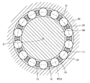
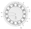
- FIG. 1 is a cross-sectional view showing a roller bearing structure according to an embodiment of the present invention, and shows a cross section in a plane orthogonal to the axis of the roller bearing.
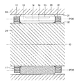
- FIG. 2 is a longitudinal sectional view showing the roller bearing structure of the embodiment, and shows a cross section in a plane including the axis of the roller bearing.
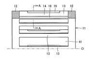
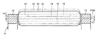
- FIG. 3 is a longitudinal sectional view showing the cage of the same embodiment, and displays the upper half portion of the cage represented by a one-dot chain line.
- the roller bearing structure of this embodiment includes a cage 11, rollers 21, an outer raceway surface 31, and an inner raceway surface 32.
- the outer raceway surface 31 is an inner circumferential surface of the housing 33
- the inner raceway surface 32 is an outer circumferential surface of the shaft 34.
- a plurality of rollers 21 and a cage 11 are provided in an annular space defined by the outer raceway surface 31 and the inner raceway surface 32.
- the roller 21 is a rolling element, and is a needle roller that rolls on the outer raceway surface 31 and rolls on the inner raceway surface 32.
- the cage 11 holds the rollers 21 at equal intervals in the circumferential direction.
- the housing 33 holds the shaft 34 rotatably via the plurality of rollers 21.
- the cage 11 holds the roller 21 so as not to drop off, so that the cage 11 and the roller 21 constitute a roller with a cage.
- the cage 11 is in the neutral position when the axis of the cage 11 coincides with the axis of the shaft 34.
- the cage 11 in the neutral position is theoretically concentric with the outer raceway surface 31 and the inner raceway surface 32.
- the cage 11 in the neutral position is concentric with a pitch circle PCD, which is a theoretical circle drawn by the center of the roller 21 rolling on the outer raceway surface 31 and the inner raceway surface 32.
- the cage 11 has a cylindrical shape, and a plurality of columns that extend in the direction of the axis O and connect the pair of rings 12 and 12 that are arranged in one and the other in the direction of the axis O. Part 13.
- the column portions 13 are arranged at equal intervals in the circumferential direction, and form pockets 41 for accommodating the rollers 21 between the adjacent column portions 13 and 13. Since the inner diameter of the cage 11 is larger than the outer diameter of the inner raceway surface 32 and the outer diameter of the cage 11 is smaller than the inner diameter of the outer raceway surface 31, the rolling surface of the roller 21 is the inner circumferential surface of the cage 11. And protrude from the outer peripheral surface.
- the wall surface 14 of the column 13 facing the pocket 41 faces the rolling surface of the roller 21 accommodated in the pocket 41 through a sufficient gap.
- An outer diameter side protrusion 15 projecting in the circumferential direction is formed on the outer diameter side of the wall surface 14, and an inner diameter side protrusion 16 protruding in the circumferential direction is formed on the inner diameter side of the wall surface 14.
- the outer diameter side protrusion 15 is a protrusion provided in the central region in the axial direction of the column portion 13 and extending in the axial direction.
- the axial end of the outer diameter side protrusion 15 extends from the ring portion 12. is seperated.
- the inner diameter side protrusion 16 is a protrusion extending in the axial direction, and the end of the inner diameter side protrusion 16 in the axial direction is connected to a pair of ring portions 12 and 12, respectively.
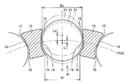
- FIG. 4 is an enlarged cross-sectional view of the roller with cage according to the embodiment.
- the cross-sectional shape of the pillar portion 13 shown in FIG. 4 represents the AA cross section of FIG.
- FIG. 5 is an enlarged longitudinal sectional view showing the roller with cage according to the embodiment.
- the distance Bo between the pair of outer diameter side protrusions 15 that face each other via the pocket 41 is smaller than the diameter of the roller 21, thereby preventing the outer diameter side protrusion 15 from falling off the roller 21 in the outer diameter direction.
- the distance Bi between the pair of inner diameter side protrusions 16 facing each other through the pocket 41 is smaller than the diameter of the roller 21, thereby preventing the inner diameter side protrusion 16 from falling off in the inner diameter direction of the roller 21.
- the roller 21 is held in the pocket 41.
- the cage 11 is in a neutral position, and a pitch circle PCD which is a theoretical circle drawn by the center of the roller 21 rolling on the outer raceway surface 31 and the inner raceway surface 32 becomes a concentric circle.
- the roller 21 is in a position indicated by a solid line in FIG.
- the roller 21 has not moved to either the outer diameter side or the inner diameter side of the cage, and the outer diameter side protruding portion 15 and the inner diameter side protruding portion 16 are rolled on the outer peripheral surface of the roller 21 through a gap. Facing the moving surface.
- the position of the roller 21 indicated by a solid line in FIG. 4 is set as a reference position of the roller 21 in the cage 11.
- the roller 21 can move from the reference position of the solid line to the outer diameter side until it comes into contact with the pair of outer diameter side protrusions 15 as indicated by a two-dot chain line in FIG. 4.
- the maximum amount of movement of the roller 21 allowed by the outer diameter side protrusion 15 is indicated by Lo from a predetermined pitch circle PCD.
- the roller 21 can move from the reference position of the solid line to the inner diameter side until it comes into contact with the pair of inner diameter side protrusions 16, as indicated by a broken line in FIG.
- the maximum amount of movement of the roller 21 allowed by the inner diameter side protrusion 16 is indicated by Li from a predetermined pitch circle PCD.
- the relationship between the allowable movement amount Lo and the allowable movement amount Li satisfies the relationship Lo> Li.
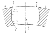
- FIG. 6 is an enlarged cross-sectional view of the cage of the same embodiment.
- the wall surface 14 is parallel to the virtual plane reference plane C including the axis O of the cage 11 and passing through the circumferential center of the pocket 41.
- the inclination angle ⁇ of the inclined surface 15i on the inner diameter side of the outer diameter side protrusion 15 as viewed from the reference surface C is set so that the molding die can be easily forcibly removed toward the outer diameter side when the retainer 11 is molded, and the roller 21 has an outer diameter.
- the slope is gentle so that it can be easily inserted from the side.
- the inclination angle ⁇ of the inclined surface 16o on the outer diameter side of the inner diameter side protrusion 16 viewed from the reference surface C is relatively steep.
- the inclination angle ⁇ of the inclined surface 15 i and the inclination angle ⁇ of the inclined surface 16 o satisfy ⁇ ⁇ . That is, the taper angle of the pair of inclined surfaces 16o that come in contact with the roller 21 relatively on the inner diameter side is steeper than the taper angle of the pair of inclined surfaces 15i that contact the roller 21 relatively on the outer diameter side. Is done.
- FIG. 7 is a cross-sectional view showing a state in which the cage is eccentrically moved from the neutral position in the direction of the arrow.
- FIG. 8 is an enlarged cross-sectional view of a portion VIII surrounded by a two-dot chain line of the roller with cage of FIG.
- FIG. 9 is an enlarged cross-sectional view of a portion IX surrounded by a two-dot chain line of the roller with cage of FIG.
- the roller 21 on the eccentric movement direction side moves from the reference position to the Li inner diameter side and contacts the inner diameter side protrusion 16. Further, as shown in FIG. 9, the roller 21 on the opposite side to the eccentric movement direction moves from the reference position to the Li outer diameter side.
- the roller 21 since the relationship of the allowable movement amount Lo> the allowable movement amount Li is satisfied, the roller 21 does not come into contact with the outer diameter side protruding portion 15, and the rolling surface of the roller 21 and the outer diameter side protruding portion 15 There is a gap between them.
- allowable movement amount Lo> allowable movement amount Li since the relationship of allowable movement amount Lo> allowable movement amount Li is satisfied, even if the cage 11 moves eccentrically, the maximum eccentric movement amount is restricted to Li. As a result, it is possible to prevent the rollers 21 from being sandwiched between the pair of inclined surfaces 15i having a gently inclined taper angle and being sandwiched between the outer diameter side protruding portions 15 like a wedge. Therefore, the rolling resistance of the roller 21 can be reduced, and the rotational resistance of the roller bearing can be reduced.
- the cage 11 of the roller with cage and the outer raceway surface 31 that is the inner circumferential surface of the housing 33 are aligned so as to be coaxial, and one end surface of the cage 11 And the other end face of the housing 33 face each other.
- a roller with a cage comprising the cage 11 and a plurality of rollers 21 is inserted into the outer raceway surface 31 of the housing 33 in the direction of the arrow and incorporated into the housing 33, the roller 21 is moved from the reference position to the outside of the cage 11. It is assumed that the allowable movement amount Lo has moved to the radial side.
- Chamfering is provided at both ends of the roller 21 in the axial direction. This chamfering is a roundness provided at the corner between the rolling surface that becomes the outer peripheral surface of the roller 21 and the end face of the roller 21, and the radius of curvature of the rounding is a radius Rr in a side view of the roller 21. Further, a chamfer is provided at the axial end of the housing 33. This chamfering is roundness provided at the corner between the outer raceway surface 31 that is the inner peripheral surface of the housing 33 and the end face of the housing 33, and the radius of curvature of the rounding is a radius Rh when viewed in the direction perpendicular to the axis of the roller bearing.
- the allowable movement amount Lo is a chamfering radius Rr provided at both axial ends of the roller 21 and a chamfering radius Rh of the housing 33 provided at the axial end of the outer raceway surface 31. It is made smaller than the sum (Lo ⁇ Rr + Rh). According to this embodiment, even when the roller 21 is moved to the outer diameter side of the retainer 21 in the assembling work of the roller with retainer, the chamfering of the roller 21 comes into contact with the chamfering of the housing 33, and the roller 21. Can be guided to the outer raceway surface 31 of the housing 33. Therefore, the assembling work can be performed efficiently.
- the cage 11 of the roller with cage and the inner raceway surface 32 that is the outer peripheral surface of the shaft 34 are aligned so as to be coaxial, and one end surface of the cage 11 The other end face of the shaft 34 is faced. Then, when the roller with retainer made up of the retainer 11 and the plurality of rollers 21 is inserted in the direction of the arrow into the inner raceway surface 32 that becomes the outer peripheral surface of the shaft 34 and incorporated in the shaft 34, the roller 21 is held from the reference position. It is assumed that the allowable movement amount Li is moved to the inner diameter side of the container 11.
- Chamfering is provided at the axial end of the shaft 34. This chamfering is roundness provided at the corner between the inner raceway surface 32 that becomes the outer peripheral surface of the shaft 34 and the end surface of the shaft 34, and the radius of curvature of the rounding is a radius Rs when viewed in the direction perpendicular to the axis of the roller bearing.
- the allowable movement amount Li is a chamfering radius Rr provided at both axial ends of the roller 21 and a chamfering radius Rs of the shaft 34 provided at the axial end of the inner raceway surface 32. It is made smaller than the sum (Li ⁇ Rr + Rs). According to this embodiment, even when the roller 21 is moved to the inner diameter side of the cage 21 in the assembling work of the roller with cage, the chamfering of the roller 21 comes into contact with the chamfering of the shaft 34 and the roller 21 is moved. It can be led to the inner raceway surface 32 of the shaft 34. Therefore, the assembling work can be performed efficiently.
- the roller 21 may be a roller other than a needle roller, for example, a cylindrical roller.
- the outer diameter side protrusion 15 and the inner diameter side protrusion 16 of the present embodiment are protrusions extending continuously in the direction of the axis O, the outer diameter side protrusion 15 and the inner diameter are not shown.
- a plurality of at least one of the side protrusions 16 may be arranged at intervals in the direction of the axis O of the cage 11.
- roller bearing cage according to the present invention is advantageously used in rolling bearings.
Landscapes
- Engineering & Computer Science (AREA)
- General Engineering & Computer Science (AREA)
- Mechanical Engineering (AREA)
- Rolling Contact Bearings (AREA)
Priority Applications (3)
| Application Number | Priority Date | Filing Date | Title |
|---|---|---|---|
| CN201380015683.1A CN104204577B (zh) | 2012-03-23 | 2013-02-25 | 滚子轴承的保持器及滚子轴承结构 |
| US14/386,058 US9388857B2 (en) | 2012-03-23 | 2013-02-25 | Cage of roller bearing and roller bearing structure |
| EP13763789.8A EP2829753B1 (fr) | 2012-03-23 | 2013-02-25 | Dispositif de retenue pour un roulement à rouleaux, et structure de roulement à rouleaux |
Applications Claiming Priority (2)
| Application Number | Priority Date | Filing Date | Title |
|---|---|---|---|
| JP2012-067337 | 2012-03-23 | ||
| JP2012067337A JP6422625B2 (ja) | 2012-03-23 | 2012-03-23 | 針状ころ軸受の保持器および針状ころ軸受構造 |
Publications (1)
| Publication Number | Publication Date |
|---|---|
| WO2013140948A1 true WO2013140948A1 (fr) | 2013-09-26 |
Family
ID=49222411
Family Applications (1)
| Application Number | Title | Priority Date | Filing Date |
|---|---|---|---|
| PCT/JP2013/054687 Ceased WO2013140948A1 (fr) | 2012-03-23 | 2013-02-25 | Dispositif de retenue pour un roulement à rouleaux, et structure de roulement à rouleaux |
Country Status (5)
| Country | Link |
|---|---|
| US (1) | US9388857B2 (fr) |
| EP (1) | EP2829753B1 (fr) |
| JP (1) | JP6422625B2 (fr) |
| CN (1) | CN104204577B (fr) |
| WO (1) | WO2013140948A1 (fr) |
Families Citing this family (9)
| Publication number | Priority date | Publication date | Assignee | Title |
|---|---|---|---|---|
| JP6369083B2 (ja) * | 2013-11-25 | 2018-08-08 | 株式会社ジェイテクト | 分割保持器及びころ軸受 |
| WO2015129709A1 (fr) * | 2014-02-25 | 2015-09-03 | Ntn株式会社 | Roulement à rouleaux coniques |
| JP6266401B2 (ja) * | 2014-02-25 | 2018-01-24 | Ntn株式会社 | 円すいころ軸受 |
| US10415429B2 (en) * | 2015-09-25 | 2019-09-17 | General Electric Company | Planet gearbox with cylindrical roller bearing with high density roller packing |
| JP6815107B2 (ja) * | 2016-07-06 | 2021-01-20 | 日本トムソン株式会社 | 保持器ずれ防止機構を備えた有限直動案内ユニット |
| JP2018080718A (ja) | 2016-11-14 | 2018-05-24 | 日本精工株式会社 | 円筒ころ軸受 |
| JP2017125616A (ja) * | 2017-04-24 | 2017-07-20 | Ntn株式会社 | ころ軸受の保持器およびころ軸受構造 |
| JP2019056387A (ja) * | 2017-09-20 | 2019-04-11 | Ntn株式会社 | 保持器付きころ |
| JP2024168656A (ja) * | 2023-05-24 | 2024-12-05 | 日本精工株式会社 | 円筒ころ軸受 |
Citations (5)
| Publication number | Priority date | Publication date | Assignee | Title |
|---|---|---|---|---|
| JPH07103240A (ja) * | 1993-09-30 | 1995-04-18 | Ntn Corp | 保持器付き針状ころ |
| JP2000145790A (ja) | 1998-11-11 | 2000-05-26 | Ntn Corp | 保持器付き針状ころ |
| JP2000205271A (ja) * | 1999-01-20 | 2000-07-25 | Hitachi Constr Mach Co Ltd | ころ軸受用保持器 |
| JP2005140269A (ja) * | 2003-11-07 | 2005-06-02 | Ntn Corp | 円筒ころ軸受 |
| JP2006242284A (ja) * | 2005-03-03 | 2006-09-14 | Nsk Ltd | 鍔付円筒ころ軸受 |
Family Cites Families (9)
| Publication number | Priority date | Publication date | Assignee | Title |
|---|---|---|---|---|
| US2883245A (en) * | 1956-11-28 | 1959-04-21 | Norma Hoffmann Bearings Corp | Retainer for anti-friction bearings |
| SE432977B (sv) * | 1982-06-09 | 1984-04-30 | Skf Ab | Rullager med gjuten plasthallare |
| JPS61146622U (fr) * | 1985-03-05 | 1986-09-10 | ||
| JP2528882Y2 (ja) * | 1990-08-03 | 1997-03-12 | 日本トムソン株式会社 | エンジン用ころ軸受 |
| JP3668274B2 (ja) * | 1995-02-08 | 2005-07-06 | 日本トムソン株式会社 | 保持器付きころ |
| JP3926865B2 (ja) * | 1996-02-16 | 2007-06-06 | 株式会社ジェイテクト | ころ軸受用の合成樹脂製保持器 |
| DE19754836A1 (de) * | 1997-12-10 | 1999-06-17 | Schaeffler Waelzlager Ohg | Nadellagerkäfig und Verfahren zu seiner Herstellung |
| DE102004046789B4 (de) * | 2003-09-30 | 2014-10-09 | Ntn Corp. | Zylinderrollenlager |
| CN101187399B (zh) * | 2003-09-30 | 2010-06-02 | Ntn株式会社 | 圆柱滚子轴承 |
-
2012
- 2012-03-23 JP JP2012067337A patent/JP6422625B2/ja active Active
-
2013
- 2013-02-25 EP EP13763789.8A patent/EP2829753B1/fr not_active Not-in-force
- 2013-02-25 WO PCT/JP2013/054687 patent/WO2013140948A1/fr not_active Ceased
- 2013-02-25 CN CN201380015683.1A patent/CN104204577B/zh active Active
- 2013-02-25 US US14/386,058 patent/US9388857B2/en active Active
Patent Citations (5)
| Publication number | Priority date | Publication date | Assignee | Title |
|---|---|---|---|---|
| JPH07103240A (ja) * | 1993-09-30 | 1995-04-18 | Ntn Corp | 保持器付き針状ころ |
| JP2000145790A (ja) | 1998-11-11 | 2000-05-26 | Ntn Corp | 保持器付き針状ころ |
| JP2000205271A (ja) * | 1999-01-20 | 2000-07-25 | Hitachi Constr Mach Co Ltd | ころ軸受用保持器 |
| JP2005140269A (ja) * | 2003-11-07 | 2005-06-02 | Ntn Corp | 円筒ころ軸受 |
| JP2006242284A (ja) * | 2005-03-03 | 2006-09-14 | Nsk Ltd | 鍔付円筒ころ軸受 |
Non-Patent Citations (1)
| Title |
|---|
| See also references of EP2829753A4 |
Also Published As
| Publication number | Publication date |
|---|---|
| EP2829753A1 (fr) | 2015-01-28 |
| EP2829753A4 (fr) | 2016-01-13 |
| JP2013199955A (ja) | 2013-10-03 |
| JP6422625B2 (ja) | 2018-11-14 |
| CN104204577A (zh) | 2014-12-10 |
| US9388857B2 (en) | 2016-07-12 |
| US20150043862A1 (en) | 2015-02-12 |
| CN104204577B (zh) | 2017-06-09 |
| EP2829753B1 (fr) | 2017-09-06 |
Similar Documents
| Publication | Publication Date | Title |
|---|---|---|
| JP6422625B2 (ja) | 針状ころ軸受の保持器および針状ころ軸受構造 | |
| US8858086B2 (en) | Rolling bearing | |
| JP6212923B2 (ja) | 円すいころ軸受 | |
| CN102549284B (zh) | 单剖分式保持架 | |
| JP6507764B2 (ja) | 円すいころ軸受 | |
| US20190368540A1 (en) | Rolling bearing cage and rolling bearing | |
| EP3385552B1 (fr) | Palier à rouleaux à alignement automatique | |
| WO2017047727A1 (fr) | Roulement à rouleaux coniques et procédé de fabrication pour roulement à rouleaux coniques | |
| US8007184B2 (en) | Self-aligning roller bearing with retainer and manufacturing method for self-aligning roller bearing retainer | |
| JP2013145012A (ja) | スラストころ軸受およびスラストころ軸受装置 | |
| WO2015129709A1 (fr) | Roulement à rouleaux coniques | |
| JP2008215475A (ja) | 保持器付ころ | |
| US9587676B2 (en) | Self-aligning roller bearing | |
| JP2005069282A (ja) | 円筒ころ軸受 | |
| JP6790517B2 (ja) | 円すいころ軸受 | |
| JP2017125616A (ja) | ころ軸受の保持器およびころ軸受構造 | |
| WO2019138937A1 (fr) | Rouleau équipé d'un dispositif de retenue et structure de support d'engrenage planétaire | |
| JP2012219994A (ja) | ころがり軸受 | |
| WO2023063043A1 (fr) | Roulement à rouleaux cylindriques | |
| US9689423B2 (en) | Rolling bearing | |
| JP6266401B2 (ja) | 円すいころ軸受 | |
| JP5909893B2 (ja) | ラジアルニードル軸受 | |
| JP2017125616A5 (fr) | ||
| JP2016089914A (ja) | 自動調心ころ軸受 | |
| JP6003022B2 (ja) | 転がり軸受用保持器 |
Legal Events
| Date | Code | Title | Description |
|---|---|---|---|
| 121 | Ep: the epo has been informed by wipo that ep was designated in this application |
Ref document number: 13763789 Country of ref document: EP Kind code of ref document: A1 |
|
| REEP | Request for entry into the european phase |
Ref document number: 2013763789 Country of ref document: EP |
|
| WWE | Wipo information: entry into national phase |
Ref document number: 2013763789 Country of ref document: EP |
|
| WWE | Wipo information: entry into national phase |
Ref document number: 14386058 Country of ref document: US |
|
| NENP | Non-entry into the national phase |
Ref country code: DE |