WO2013140990A1 - Cycle de réfrigération et vitrine de réfrigération - Google Patents
Cycle de réfrigération et vitrine de réfrigération Download PDFInfo
- Publication number
- WO2013140990A1 WO2013140990A1 PCT/JP2013/055508 JP2013055508W WO2013140990A1 WO 2013140990 A1 WO2013140990 A1 WO 2013140990A1 JP 2013055508 W JP2013055508 W JP 2013055508W WO 2013140990 A1 WO2013140990 A1 WO 2013140990A1
- Authority
- WO
- WIPO (PCT)
- Prior art keywords
- refrigerant
- condenser
- compressor
- ejector
- expansion valve
- Prior art date
- Legal status (The legal status is an assumption and is not a legal conclusion. Google has not performed a legal analysis and makes no representation as to the accuracy of the status listed.)
- Ceased
Links
Images



Classifications
-
- F—MECHANICAL ENGINEERING; LIGHTING; HEATING; WEAPONS; BLASTING
- F25—REFRIGERATION OR COOLING; COMBINED HEATING AND REFRIGERATION SYSTEMS; HEAT PUMP SYSTEMS; MANUFACTURE OR STORAGE OF ICE; LIQUEFACTION SOLIDIFICATION OF GASES
- F25B—REFRIGERATION MACHINES, PLANTS OR SYSTEMS; COMBINED HEATING AND REFRIGERATION SYSTEMS; HEAT PUMP SYSTEMS
- F25B40/00—Subcoolers, desuperheaters or superheaters
-
- F—MECHANICAL ENGINEERING; LIGHTING; HEATING; WEAPONS; BLASTING
- F25—REFRIGERATION OR COOLING; COMBINED HEATING AND REFRIGERATION SYSTEMS; HEAT PUMP SYSTEMS; MANUFACTURE OR STORAGE OF ICE; LIQUEFACTION SOLIDIFICATION OF GASES
- F25B—REFRIGERATION MACHINES, PLANTS OR SYSTEMS; COMBINED HEATING AND REFRIGERATION SYSTEMS; HEAT PUMP SYSTEMS
- F25B41/00—Fluid-circulation arrangements
-
- F—MECHANICAL ENGINEERING; LIGHTING; HEATING; WEAPONS; BLASTING
- F25—REFRIGERATION OR COOLING; COMBINED HEATING AND REFRIGERATION SYSTEMS; HEAT PUMP SYSTEMS; MANUFACTURE OR STORAGE OF ICE; LIQUEFACTION SOLIDIFICATION OF GASES
- F25B—REFRIGERATION MACHINES, PLANTS OR SYSTEMS; COMBINED HEATING AND REFRIGERATION SYSTEMS; HEAT PUMP SYSTEMS
- F25B2341/00—Details of ejectors not being used as compression device; Details of flow restrictors or expansion valves
- F25B2341/001—Ejectors not being used as compression device
- F25B2341/0011—Ejectors with the cooled primary flow at reduced or low pressure
-
- F—MECHANICAL ENGINEERING; LIGHTING; HEATING; WEAPONS; BLASTING
- F25—REFRIGERATION OR COOLING; COMBINED HEATING AND REFRIGERATION SYSTEMS; HEAT PUMP SYSTEMS; MANUFACTURE OR STORAGE OF ICE; LIQUEFACTION SOLIDIFICATION OF GASES
- F25B—REFRIGERATION MACHINES, PLANTS OR SYSTEMS; COMBINED HEATING AND REFRIGERATION SYSTEMS; HEAT PUMP SYSTEMS
- F25B2341/00—Details of ejectors not being used as compression device; Details of flow restrictors or expansion valves
- F25B2341/001—Ejectors not being used as compression device
- F25B2341/0012—Ejectors with the cooled primary flow at high pressure
-
- F—MECHANICAL ENGINEERING; LIGHTING; HEATING; WEAPONS; BLASTING
- F25—REFRIGERATION OR COOLING; COMBINED HEATING AND REFRIGERATION SYSTEMS; HEAT PUMP SYSTEMS; MANUFACTURE OR STORAGE OF ICE; LIQUEFACTION SOLIDIFICATION OF GASES
- F25B—REFRIGERATION MACHINES, PLANTS OR SYSTEMS; COMBINED HEATING AND REFRIGERATION SYSTEMS; HEAT PUMP SYSTEMS
- F25B2341/00—Details of ejectors not being used as compression device; Details of flow restrictors or expansion valves
- F25B2341/001—Ejectors not being used as compression device
- F25B2341/0014—Ejectors with a high pressure hot primary flow from a compressor discharge
-
- F—MECHANICAL ENGINEERING; LIGHTING; HEATING; WEAPONS; BLASTING
- F25—REFRIGERATION OR COOLING; COMBINED HEATING AND REFRIGERATION SYSTEMS; HEAT PUMP SYSTEMS; MANUFACTURE OR STORAGE OF ICE; LIQUEFACTION SOLIDIFICATION OF GASES
- F25B—REFRIGERATION MACHINES, PLANTS OR SYSTEMS; COMBINED HEATING AND REFRIGERATION SYSTEMS; HEAT PUMP SYSTEMS
- F25B2341/00—Details of ejectors not being used as compression device; Details of flow restrictors or expansion valves
- F25B2341/001—Ejectors not being used as compression device
- F25B2341/0015—Ejectors not being used as compression device using two or more ejectors
Definitions
- the present invention relates to a refrigeration cycle and a refrigeration showcase provided with an ejector. Specifically, an ejector is provided between a compressor and a condenser, and refrigerant compressed by the compressor is used as a drive flow of the ejector.
- the present invention relates to a refrigeration cycle and a refrigeration showcase in which low-pressure refrigerant upstream of a compressor can be sucked and supplied to a condenser due to the generated static pressure drop.
- An internal heat exchanger that exchanges heat with the refrigerant before the heat treatment, an evaporator that evaporates the refrigerant expanded by the first expansion valve by heat exchange, and a refrigerant that has passed through the second expansion valve and the internal heat exchanger are used as a driving flow.
- an ejector that mixes the drive flow and the suction flow and supplies them to the compressor using the refrigerant that has passed through the internal heat exchanger and the first expansion valve as a suction flow (for example, Patent Document 1). reference).
- the problem to be solved by the present invention that addresses such problems is to provide a refrigeration cycle and a refrigeration showcase that can improve the efficiency by using the kinetic energy of the refrigerant compressed by the compressor. There is to do.
- a refrigeration cycle includes a compressor that compresses a refrigerant, a condenser that condenses the refrigerant compressed by the compressor, and evaporates the refrigerant condensed by the condenser.
- the refrigeration cycle according to the present invention may include an expansion valve that expands the refrigerant condensed in the condenser and supplies the refrigerant to the evaporator.
- the refrigeration cycle according to the present invention includes a first expansion valve that expands one of the refrigerant branched downstream of the condenser and supplies the refrigerant to the evaporator, and the other of the refrigerant branched downstream of the condenser.
- You may comprise including the 2nd expansion valve to expand, and the heat exchanger which evaporates the refrigerant
- the refrigeration cycle according to the present invention includes a first expansion valve that expands one of the refrigerant branched downstream of the condenser and supplies the refrigerant to the evaporator, and the other of the refrigerant branched downstream of the condenser.
- the suction flow may be configured to include another ejector that mixes the driving flow and the suction flow and supplies the mixed flow to the compressor.
- the refrigeration cycle according to the present invention includes another ejector that uses the refrigerant condensed in the condenser as a drive flow, mixes the drive flow and the suction flow, and supplies the mixture to the compressor, and the compressor from the other ejector to the compressor.
- a gas-liquid separator that separates a liquid-phase refrigerant from a refrigerant supplied to the refrigerant, and the liquid-phase refrigerant separated by the gas-liquid separator is evaporated by the evaporator and used as a suction flow of the other ejector You may comprise so that it may supply.
- the refrigeration cycle according to the present invention includes an expansion valve that expands one of the refrigerants branched downstream of the condenser, and the other of the refrigerants branched downstream of the condenser as a driving flow, and a driving flow and a suction flow.
- a first evaporator that mixes and supplies to the compressor, the evaporator evaporates the refrigerant expanded by the expansion valve and supplies the refrigerant as a suction flow of the other ejector, You may comprise including the 2nd evaporator which evaporates the refrigerant
- the refrigeration showcase according to the present invention includes the refrigeration cycle according to the present invention.
- an ejector is provided between the compressor and the condenser, the refrigerant compressed by the compressor is used as a drive flow of the ejector, and the pressure is lower than the refrigerant compressed by the compressor.
- FIG. 1 a condenser 1, an expansion valve 2, an evaporator 3, a compressor 4 and The ejector 5 includes refrigerant pipes A to E that connect them.
- the condenser 1 cools and condenses the refrigerant compressed by the compressor 4 by heat exchange with the outside air.
- the state of the refrigerant moves from E to A in FIG.
- the refrigerant condensed in the condenser 1 is supplied to the expansion valve 2 through the refrigerant pipe A.
- the expansion valve 2 expands the refrigerant condensed in the condenser 1 by reducing the pressure.
- the state of the refrigerant moves from A to B in FIG.
- the refrigerant expanded by the expansion valve 2 is supplied to the evaporator 3 through the refrigerant pipe B.
- the evaporator 3 cools air and evaporates the refrigerant by exchanging heat between the refrigerant that has passed through the expansion valve 2 and the air.
- the refrigerant is preferably heat-exchanged (heated) so as to have a predetermined degree of superheat when it passes through the evaporator 3.
- the state of the refrigerant moves from B to C in FIG.
- the refrigerant evaporated in the evaporator 3 passes through the refrigerant pipe C and is branched into the refrigerant pipes C 1 and C 2 at the branch point S downstream of the evaporator 3.
- Refrigerant branched into refrigerant pipe C 1 is supplied to the compressor 4.
- the compressor 4 compresses the refrigerant and raises the temperature and pressure, and can be selected from known compressors such as a reciprocating compressor, a swash plate compressor, a screw compressor, and a scroll compressor.
- the refrigerant compressed by the compressor 4 is supplied as a driving flow to the ejector 5 through the refrigerant pipe D.
- Branched refrigerant to the refrigerant pipe C 2 is supplied as a suction flow into the ejector 5.
- the ejector 5 is provided between the compressor 4 and the condenser 1, uses the refrigerant compressed by the compressor 4 as a driving flow, and at least one of the refrigerant evaporated in the evaporator 3 due to a decrease in static pressure caused by the driving flow. Are sucked through the refrigerant pipe C 2 , and the driving flow and the suction flow are mixed and supplied to the condenser 1. As shown in FIG. 2, the refrigerant evaporated in the evaporator 3 supplied as a suction flow has a lower pressure than the refrigerant compressed in the compressor 4 supplied as a drive flow, and the drive flow and the suction flow are mixed. Then, the state of the refrigerant moves from C and D to E in FIG. The refrigerant mixed in the ejector 5 is supplied to the condenser 1 through the refrigerant pipe E.
- the refrigeration cycle includes a compressor 4 that compresses the refrigerant, a condenser 1 that condenses the refrigerant compressed by the compressor 4, and an expansion valve 2 that expands the refrigerant condensed by the condenser 1. And an evaporator 3 that evaporates the refrigerant expanded by the expansion valve 2 and supplies the evaporated refrigerant to the compressor 4, and an ejector 5 provided between the compressor 4 and the condenser 1.
- the compressor 4 refrigerant and driven flow, at least a portion of the low-pressure refrigerant than refrigerant compressed by the compressor 4 (the refrigerant is branched into refrigerant pipe C 2) and the suction flow, driven flow And the suction flow are mixed and supplied to the condenser 1, using the kinetic energy of the refrigerant compressed by the compressor 4, at least a part of the low-pressure refrigerant is bypassed by the compressor 4 and the condenser 1 can be supplied. Therefore, the work of the compressor 4 can be reduced and the efficiency of the refrigeration cycle can be improved.
- the ejector 5 at least a portion of the refrigerant evaporated in the evaporator 3 a (refrigerant branched into refrigerant pipe C 2) for the suction flow, to improve the efficiency of the ejector 5 Can do.
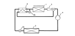
- This refrigeration cycle includes a condenser 1, a heat exchanger 6, a first expansion valve 2a, an evaporator 3, a compressor 4, an ejector 5, a second expansion valve 2b, and a refrigerant pipe connecting them.
- a to H are included.
- a different part from 1st Embodiment is demonstrated.
- the refrigerant condensed in the condenser 1 is supplied to the heat exchanger 6 through the refrigerant pipe A.
- the heat exchanger 6 further cools the refrigerant condensed in the condenser 1 by exchanging heat between the refrigerant condensed in the condenser 1 and the refrigerant expanded in the second expansion valve 2b, and expands in the second expansion valve 2b.
- the evaporated refrigerant is evaporated.
- the refrigerant cooled by the heat exchanger 6 passes through the refrigerant pipe F and is branched into the refrigerant pipes F 1 and F 2 at the branch point S downstream of the condenser 1.
- Refrigerant branched into refrigerant piping F 1 is supplied to the first expansion valve 2a, expanded in the first expansion valve 2a, it is supplied to the evaporator 3 through the refrigerant pipe B, and evaporated in the evaporator 3, the refrigerant
- the refrigerant is supplied to the compressor 4 through the pipe C, compressed by the compressor 4, and supplied to the ejector 5 through the refrigerant pipe D as a driving flow.
- the flow rate of the refrigerant is branched into refrigerant piping F 1 can be controlled by adjusting the first expansion valve 2a, the respective degree of opening of the second expansion valve 2b.
- Branched refrigerant to the refrigerant pipe F 2 is supplied to the second expansion valve 2b.
- the second expansion valve 2b expands the refrigerant condensed in the condenser 1 by reducing the pressure.
- the refrigerant expanded by the second expansion valve 2b is supplied to the heat exchanger 6 through the refrigerant pipe G.
- the flow rate of the refrigerant is branched into refrigerant piping F 2 can be controlled by adjusting the first expansion valve 2a, the respective degree of opening of the second expansion valve 2b.
- the heat exchanger 6 evaporates the refrigerant supplied to the heat exchanger 6 by exchanging heat with the refrigerant upstream from the branch point S condensed by the condenser 1.
- the refrigerant evaporated in the heat exchanger 6 is supplied as a suction flow to the ejector 5 through the refrigerant pipe H.
- the ejector 5 is provided between the compressor 4 and the condenser 1, uses the refrigerant compressed by the compressor 4 as a driving flow, and is a compressor evaporated in the heat exchanger 6 due to a decrease in static pressure caused by the driving flow.
- a refrigerant having a pressure lower than that of the refrigerant compressed in 4 is sucked through the refrigerant pipe H, and the driving flow and the suction flow are mixed and supplied to the condenser 1.
- the refrigeration cycle includes the compressor 4 that compresses the refrigerant, the condenser 1 that condenses the refrigerant compressed by the compressor 4, and the refrigerant branched at the branch point S downstream of the condenser 1.
- the heat exchanger 6 for evaporating the gas and the ejector 5 provided between the compressor 4 and the condenser 1 are configured, and the ejector 5 uses the refrigerant compressed by the compressor 4 as a driving flow, In order to supply at least a part of the refrigerant having a pressure lower than that of the refrigerant compressed by the compressor 4 (the refrigerant evaporated in the heat exchanger 6) as the suction flow, and mix the drive flow and the suction flow to the condenser 1, Low-pressure refrigerant using kinetic energy of refrigerant compressed by compressor 4 At least a portion, to bypass the compressor 4 can be supplied to the condenser 1.
- the work of the compressor 4 can be reduced and the efficiency of the refrigeration cycle can be improved. Moreover, since the kinetic energy of the refrigerant
- the ejector 5 since the ejector 5 uses the refrigerant evaporated in the heat exchanger 6 as the suction flow, the suction flow becomes only the gas-phase refrigerant, and the efficiency of the ejector 5 can be improved.
- the heat exchanger 6 evaporates the refrigerant expanded by the second expansion valve 2b by heat exchange with the refrigerant condensed by the condenser 1. That is, the refrigerant condensed by the condenser 2 is further cooled by the refrigerant expanded by the second expansion valve 2b. Therefore, the supercooling degree of the refrigerant condensed in the condenser 1 can be increased, and the efficiency of the refrigeration cycle can be improved.
- the heat exchanger 6 evaporates the refrigerant expanded by the second expansion valve 2 b by heat exchange with the refrigerant before branching at the branch point S downstream of the condenser 1. That is, the refrigerant condensed in the condenser 1 is further cooled by the refrigerant that has been cooled in advance by the heat exchanger 6. Therefore, the supercooling degree of the refrigerant condensed in the condenser 1 can be increased, and the efficiency of the refrigeration cycle can be improved.
- the heat exchanger 6 evaporates the refrigerant expanded by the second expansion valve 2b by heat exchange with the refrigerant before branching at the branch point S downstream of the condenser 1.
- the refrigerant expanded by the second expansion valve 2b evaporates by heat exchange with the refrigerant before branching at the branch point S downstream of the condenser 1 and expanding at the first expansion valve 2a.
- a configuration may be adopted.
- the opening degree of the first expansion valve 2a and the second expansion valve 2b may be configured to be controlled by a control means (not shown) according to the operation state of the refrigeration cycle.
- the operating state of the refrigeration cycle includes, but is not limited to, the outside air temperature and the temperature / pressure of the refrigerant in each part of the refrigeration cycle.
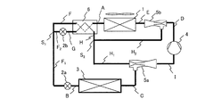
- This refrigeration cycle includes a condenser 1, a heat exchanger 6, a first expansion valve 2a, an evaporator 3, a second expansion valve 2b, a first ejector 5a (another ejector), a compressor 4, The second ejector 5b and the refrigerant pipes A to I connecting them are configured.
- a different part from 1st Embodiment and 2nd Embodiment is demonstrated.
- the refrigerant condensed in the condenser 1 passes through the refrigerant pipe A is fed to the heat exchanger 6, it is cooled in heat exchanger 6, through the refrigerant piping F, the refrigerant downstream of the branch point S 1 of the heat exchanger 6 Branches to the pipes F 1 and F 2 .
- Refrigerant branched into refrigerant piping F 1 is expanded in the first expansion valve 2a, is supplied to the evaporator 3 through the refrigerant pipe B, evaporated in the evaporator 3, the first ejector 5a through the refrigerant pipe C As a suction flow.
- Refrigerant branched into refrigerant piping F 2 is expanded in the second expansion valve 2b, through the refrigerant pipe G is supplied to the heat exchanger 6, and evaporated in the heat exchanger 6 through the refrigerant pipe H, the heat exchanger
- the refrigerant pipes H 1 and H 2 are branched at a branch point S 2 downstream of the vessel 6.
- Refrigerant branched into refrigerant pipe H 1 is supplied as a drive current to the first ejector 5a.
- the first ejector 5a uses the refrigerant evaporated in the heat exchanger 6 as a driving flow, and sucks the refrigerant evaporated in the evaporator 3 through the refrigerant pipe C due to a decrease in static pressure caused by the driving flow. And are supplied to the compressor 4 through the refrigerant pipe I.
- the refrigerant supplied to the compressor 4 is compressed, supplied through the refrigerant pipe D to the second ejector 5b as a driving flow.
- Branched refrigerant to the refrigerant pipe H 2 is supplied as a suction flow into the second ejector 5b.
- the second ejector 5b is provided between the compressor 4 and the condenser 1.
- the refrigerant compressed by the compressor 4 is used as a driving flow, and the refrigerant evaporated by the heat exchanger 6 due to a decrease in static pressure caused by the driving flow.
- At least a portion of the, and sucked through the refrigerant pipe H 2 is supplied by mixing the motive flow and suction flow to the condenser 1.
- the refrigerant mixed in the second ejector 5b is supplied to the condenser 1 through the refrigerant pipe E.
- the refrigeration cycle is branched at the compressor 4 that compresses the refrigerant, the condenser 1 that condenses the refrigerant compressed by the compressor 4, and the branch point S 1 downstream of the condenser 1.
- a first ejector 5a (another ejector) that is mixed and supplied to the compressor 4 and a second ejector 5b provided between the compressor 4 and the condenser 1 are configured, and the
- the compressor 4 Uses the refrigerant compressed by the compressor 4 as a driving flow, and the compressor 4 Since at least part of the low-pressure refrigerant than the compressed refrigerant and the suction stream (refrigerant branched into refrigerant pipe H 2), fed by mixing the motive flow and suction flow to the condenser 1, the compressor 4 By using the kinetic energy of the refrigerant compressed in step 1, at least a part of the low-pressure refrigerant can be supplied to the condenser 1 by bypassing the compressor 4. Therefore, the work of the compressor 4 can be reduced and the efficiency of the refrigeration cycle can be improved.
- the first ejector 5a has, at least a portion of the refrigerant evaporated in the heat exchanger 6 by utilizing the kinetic energy of the (refrigerant branched into refrigerant pipe H 1), was aspirated refrigerant evaporated in the evaporator 3, Since the refrigerant is supplied to the compressor 4, the work of the compressor 4 is reduced, and the efficiency of the refrigeration cycle can be improved.
- the second ejector 5b since at least a part of the refrigerant evaporated in the heat exchanger 6 (refrigerant branched into refrigerant pipe H 2) and suction flow, suction flow gas phase Therefore, the efficiency of the second ejector 5b can be improved.
- the heat exchanger 6 evaporates the refrigerant expanded by the second expansion valve 2b by heat exchange with the refrigerant condensed by the condenser 1. That is, the refrigerant condensed by the condenser 2 is further cooled by the refrigerant expanded by the second expansion valve 2b. Therefore, the supercooling degree of the refrigerant condensed in the condenser 1 can be increased, and the efficiency of the refrigeration cycle can be improved.
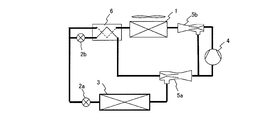
- the second ejector 5b at least a portion of the refrigerant evaporated in the heat exchanger 6 has been to a (refrigerant pipe H 2 to the branch refrigerant) the suction flow, in FIG. 6
- a part of the refrigerant supplied from the first ejector 5a to the compressor 4 may be configured as a suction flow.
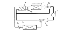
- the heat exchanger 6 is intended to be evaporated by heat exchange with the refrigerant before the refrigerant expanded by the second expansion valve 2b, which is branched at the downstream of the branch point S 1 of the condenser 1 there was however, as shown in FIG. 7, the heat exchange with the refrigerant before the refrigerant expanded by the second expansion valve 2b, expanded in the first expansion valve 2a is branched downstream of the branch point S 1 of the condenser 1 You may comprise so that it may evaporate by.
- This refrigeration cycle includes a condenser 1, a first ejector 5a (another ejector), a gas-liquid separator 7, an evaporator 3, a compressor 4, a second ejector 5b, and a refrigerant pipe connecting them.
- a to K are included.
- parts different from the first to third embodiments will be described.
- the refrigerant condensed in the condenser 1 is supplied as a driving flow to the first ejector 5a through the refrigerant pipe A, and the driving flow and the suction flow are mixed in the first ejector 5a.
- K is supplied to the compressor 4 through K.
- a gas-liquid separator 7 is provided between the first ejector 5a and the compressor 4 to separate the liquid-phase refrigerant from the refrigerant supplied from the first ejector 5a to the compressor 1.
- the refrigerant discharged from the first ejector 5a flows into the gas-liquid separator 7 through the refrigerant pipe I.
- the gas-phase refrigerant is supplied to the compressor 4 through the refrigerant pipe K, and the liquid-phase refrigerant is separated and supplied to the evaporator 3 through the refrigerant pipe J.
- the liquid-phase refrigerant supplied to the evaporator 3 evaporates in the evaporator 3 and is sucked through the refrigerant pipe C as a suction flow of the first ejector 5a due to a decrease in static pressure caused by the driving flow of the first ejector 5a. .
- the gas-phase refrigerant separated from the liquid-phase refrigerant by the gas-liquid separator 7 passes through the refrigerant pipe K and reaches the branch point S downstream of the gas-liquid separator 7. Branches to the refrigerant pipes K 1 and K 2 .
- Refrigerant branched into refrigerant piping K 1 is compressed is supplied to the compressor 4 is supplied as a drive current to the second ejector 5b through the refrigerant pipe D. It branched refrigerant to the refrigerant pipe K 2 is supplied as a suction flow into the second ejector 5b.
- the second ejector 5b is provided between the compressor 4 and the condenser 1, and uses the refrigerant compressed by the compressor 4 as a driving flow.
- the second ejector 5b evaporates in the evaporator 3 due to a decrease in static pressure caused by the driving flow. 1 is discharged from the ejector 5a least a portion of the refrigerant in the gas-liquid separator 7 to liquid-phase refrigerant separated by the gas-phase, and sucked through the refrigerant pipe K 2, by mixing the motive flow and the suction flow refrigerant pipe E To the condenser 1.
- the compressor 4 that compresses the refrigerant, the condenser 1 that condenses the refrigerant compressed by the compressor 4, and the refrigerant condensed by the condenser 1 is used as the driving flow, and the driving flow and the suction flow
- a second ejector 5b provided between the compressor 4 and the condenser 1; is configured to include a second ejector 5b is a compressed by the compressor 4 refrigerant and driven flow, at least a portion of the low-pressure refrigerant than refrigerant compressed by the
- At least a part of the low-pressure refrigerant can be supplied to the condenser 1 by bypassing the compressor 4 using the kinetic energy of the refrigerant compressed by the compressor 4. Therefore, the work of the compressor 4 can be reduced and the efficiency of the refrigeration cycle can be improved. Moreover, since the kinetic energy of the refrigerant
- the first ejector 5a uses the kinetic energy of the refrigerant condensed in the condenser 1 to suck the refrigerant evaporated in the evaporator 3 and supplies it to the compressor 4, the work of the compressor 4 is reduced. The efficiency of the refrigeration cycle can be improved.
- the second ejector 5b since at least a part of the refrigerant between the gas-liquid separator 7 and the compressor 4 (the refrigerant is branched into refrigerant piping K 2) and suction flow The suction flow becomes only the gas-phase refrigerant, and the efficiency of the second ejector 5b can be improved.
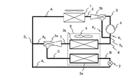
- This refrigeration cycle includes a condenser 1, an expansion valve 2, a first evaporator 3a, a first ejector 5a (another ejector), a second evaporator 3b, a compressor 4, and a second ejector 5b.
- the refrigerant pipes A to K connecting them are configured.
- parts different from the first to fourth embodiments will be described.
- the refrigerant condensed in the condenser 1 passes through the refrigerant pipe A and is branched into the refrigerant pipes A 1 and A 2 at a branch point S 1 downstream of the condenser 1.
- Refrigerant branched into refrigerant pipe A 1 is expanded in the expansion valve 2, it is supplied to the first evaporator 3a through the refrigerant pipe B, and evaporated in the first evaporator 3a, first through the refrigerant pipe C It is supplied as a suction flow to the ejector 5a.
- refrigerant branched to the refrigerant pipe A 2 is supplied as a drive current to the first ejector 5a.
- the first ejector 5a mixes and discharges the driving flow and the suction flow.
- the refrigerant discharged from the first ejector 5a is supplied to the second evaporator 3b through the refrigerant pipe I.
- Second evaporator 3b the refrigerant supplied to the compressor 4 from the first ejector 5a, in particular, condensed in the condenser 1 is branched into refrigerant piping A 2, the liquid used as the drive current of the first ejector 5a
- the phase refrigerant is evaporated by heat exchange with air.
- the second evaporator 3b and the first evaporator 3a are arranged side by side and constitute one evaporator 8 as a whole. In the evaporator 8, the second evaporator 3b is disposed upstream of the air to be cooled, and the first evaporator 3a is disposed downstream of the air to be cooled.
- the air is first cooled by the second evaporator 3b, and thereafter The first evaporator 3a is cooled.
- the evaporator 8 preferably includes a fan 9 that blows air from the second evaporator 3b toward the first evaporator 3a.
- the refrigerant evaporated in the second evaporator 3b passes through the refrigerant pipe K, is branched into refrigerant piping K 1, K 2 downstream of the branching point S 2 of the second evaporator 3b.
- Refrigerant branched into refrigerant piping K 1 is compressed is supplied to the compressor 4 is supplied as the driving flow to the second ejector 5b through the refrigerant pipe D. It branched refrigerant to the refrigerant pipe K 2 is supplied as a suction flow into the second ejector 5b.
- the second ejector 5b is provided between the compressor 4 and the condenser 1.
- the refrigerant compressed by the compressor 4 is used as a driving flow, and the first evaporator 3a and the second evaporator 5b are driven by a static pressure drop caused by the driving flow.
- the refrigeration cycle is branched at the compressor 4 that compresses the refrigerant, the condenser 1 that condenses the refrigerant compressed by the compressor 4, and the branch point S 1 downstream of the condenser 1.
- the expansion valve 2 for expanding one of the refrigerants (the refrigerant branched into the refrigerant pipe A1), the first evaporator 3a for evaporating the refrigerant expanded by the expansion valve 2, and the branch point S1 downstream of the condenser 1 the other branched refrigerant (refrigerant branched into refrigerant pipe a 2) as a driving flow, a refrigerant evaporated in the first evaporator 3a and suction flow, the compressor 4 by mixing the motive flow and suction flow Provided between the first ejector 5a to be supplied (another ejector), the second evaporator 3b for evaporating the refrigerant supplied from the first ejector 5a to the compressor 4, and the
- the second ejector 5b, and the second ejector 5b is compressed.
- the second ejector 5b since at least a part of the refrigerant evaporated in the second evaporator 3b (the refrigerant is branched into refrigerant piping K 2) and suction flow, the suction flow gas Only the phase refrigerant is used, and the efficiency of the second ejector 5b can be improved.
- This refrigeration showcase includes a refrigeration cycle according to the present invention whose embodiments are shown in FIGS. At least evaporators 3 and 8 are built in the freezer showcase, and the evaporators 3 and 8 cool the air in the freezer showcase.
- the condenser 1 constituting the refrigeration cycle may be installed outdoors in order to efficiently dissipate heat from the refrigerant.
Landscapes
- Engineering & Computer Science (AREA)
- Physics & Mathematics (AREA)
- Mechanical Engineering (AREA)
- Thermal Sciences (AREA)
- General Engineering & Computer Science (AREA)
- Jet Pumps And Other Pumps (AREA)
Applications Claiming Priority (2)
| Application Number | Priority Date | Filing Date | Title |
|---|---|---|---|
| JP2012-067759 | 2012-03-23 | ||
| JP2012067759A JP2013200056A (ja) | 2012-03-23 | 2012-03-23 | 冷凍サイクル及び冷凍ショーケース |
Publications (1)
| Publication Number | Publication Date |
|---|---|
| WO2013140990A1 true WO2013140990A1 (fr) | 2013-09-26 |
Family
ID=49222453
Family Applications (1)
| Application Number | Title | Priority Date | Filing Date |
|---|---|---|---|
| PCT/JP2013/055508 Ceased WO2013140990A1 (fr) | 2012-03-23 | 2013-02-28 | Cycle de réfrigération et vitrine de réfrigération |
Country Status (2)
| Country | Link |
|---|---|
| JP (1) | JP2013200056A (fr) |
| WO (1) | WO2013140990A1 (fr) |
Cited By (6)
| Publication number | Priority date | Publication date | Assignee | Title |
|---|---|---|---|---|
| WO2020101846A1 (fr) * | 2018-11-12 | 2020-05-22 | Carrier Corporation | Système de réfrigération |
| US10724771B2 (en) | 2015-05-12 | 2020-07-28 | Carrier Corporation | Ejector refrigeration circuit |
| US11578896B2 (en) * | 2019-04-18 | 2023-02-14 | Qingdao Haier Air-Conditioning Electronic Co., Ltd | Refrigeration system |
| US20230158861A1 (en) * | 2021-11-24 | 2023-05-25 | Volkswagen Aktiengesellschaft | Climate control system with a controlled ejector |
| IT202200013498A1 (it) | 2022-06-27 | 2023-12-27 | Giuseppe Verde | Macchina termica a ciclo inverso a compressione di liquido |
| IT202200014506A1 (it) | 2022-07-08 | 2024-01-08 | Giuseppe Verde | Macchina termica a ciclo inverso a compressione di liquido a doppio stadio |
Families Citing this family (4)
| Publication number | Priority date | Publication date | Assignee | Title |
|---|---|---|---|---|
| KR101564611B1 (ko) | 2014-02-10 | 2015-10-30 | 국립대학법인 울산과학기술대학교 산학협력단 | 이젝터식 냉동 사이클 |
| KR102082790B1 (ko) * | 2018-04-30 | 2020-02-28 | 유니셈 주식회사 | 극저온 반도체 칠러 장치 |
| KR102126782B1 (ko) * | 2019-10-14 | 2020-06-25 | 전남대학교산학협력단 | 저온 수송 냉동차량용 냉동시스템 |
| KR102345640B1 (ko) * | 2020-02-21 | 2021-12-31 | (주)피티씨 | 반도체 공정용 칠러 장치 |
Citations (4)
| Publication number | Priority date | Publication date | Assignee | Title |
|---|---|---|---|---|
| JPS50113952U (fr) * | 1974-02-25 | 1975-09-17 | ||
| JPS5737663A (en) * | 1980-08-14 | 1982-03-02 | Matsushita Electric Industrial Co Ltd | Refrigeration cycle for air conditioner |
| JP2007078318A (ja) * | 2005-09-16 | 2007-03-29 | Toshiba Kyaria Kk | 冷凍サイクル装置 |
| JP2008261628A (ja) * | 2008-08-06 | 2008-10-30 | Mitsubishi Electric Corp | 冷凍装置 |
-
2012
- 2012-03-23 JP JP2012067759A patent/JP2013200056A/ja active Pending
-
2013
- 2013-02-28 WO PCT/JP2013/055508 patent/WO2013140990A1/fr not_active Ceased
Patent Citations (4)
| Publication number | Priority date | Publication date | Assignee | Title |
|---|---|---|---|---|
| JPS50113952U (fr) * | 1974-02-25 | 1975-09-17 | ||
| JPS5737663A (en) * | 1980-08-14 | 1982-03-02 | Matsushita Electric Industrial Co Ltd | Refrigeration cycle for air conditioner |
| JP2007078318A (ja) * | 2005-09-16 | 2007-03-29 | Toshiba Kyaria Kk | 冷凍サイクル装置 |
| JP2008261628A (ja) * | 2008-08-06 | 2008-10-30 | Mitsubishi Electric Corp | 冷凍装置 |
Cited By (7)
| Publication number | Priority date | Publication date | Assignee | Title |
|---|---|---|---|---|
| US10724771B2 (en) | 2015-05-12 | 2020-07-28 | Carrier Corporation | Ejector refrigeration circuit |
| WO2020101846A1 (fr) * | 2018-11-12 | 2020-05-22 | Carrier Corporation | Système de réfrigération |
| US11578896B2 (en) * | 2019-04-18 | 2023-02-14 | Qingdao Haier Air-Conditioning Electronic Co., Ltd | Refrigeration system |
| US20230158861A1 (en) * | 2021-11-24 | 2023-05-25 | Volkswagen Aktiengesellschaft | Climate control system with a controlled ejector |
| US12049123B2 (en) * | 2021-11-24 | 2024-07-30 | Volkswagen Aktiengesellschaft | Climate control system with a controlled ejector |
| IT202200013498A1 (it) | 2022-06-27 | 2023-12-27 | Giuseppe Verde | Macchina termica a ciclo inverso a compressione di liquido |
| IT202200014506A1 (it) | 2022-07-08 | 2024-01-08 | Giuseppe Verde | Macchina termica a ciclo inverso a compressione di liquido a doppio stadio |
Also Published As
| Publication number | Publication date |
|---|---|
| JP2013200056A (ja) | 2013-10-03 |
Similar Documents
| Publication | Publication Date | Title |
|---|---|---|
| JP5805567B2 (ja) | 冷凍サイクル及び冷凍ショーケース | |
| JP2013200056A (ja) | 冷凍サイクル及び冷凍ショーケース | |
| EP2543941B1 (fr) | Installation frigorifique | |
| EP3102894B1 (fr) | Système de pompe à chaleur | |
| JP5018724B2 (ja) | エジェクタ式冷凍サイクル | |
| JP4550153B2 (ja) | ヒートポンプ装置及びヒートポンプ装置の室外機 | |
| WO2009128271A1 (fr) | Dispositif de cycle de réfrigération de type éjecteur | |
| JP5871681B2 (ja) | 冷凍サイクル及び冷凍ショーケース | |
| JP2011214753A (ja) | 冷凍装置 | |
| KR20100096857A (ko) | 공기 조화기 | |
| JP2011196684A (ja) | ヒートポンプ装置及びヒートポンプ装置の室外機 | |
| JP4767340B2 (ja) | ヒートポンプ装置の制御装置 | |
| US20160363351A1 (en) | Heat exchange apparatus and heat pump apparatus | |
| JP2009243881A (ja) | ヒートポンプ装置及びヒートポンプ装置の室外機 | |
| JP2007078318A (ja) | 冷凍サイクル装置 | |
| JP2014190581A (ja) | 直膨式冷却装置 | |
| JP2014190562A (ja) | 冷凍サイクル及び冷却機器 | |
| JP5895662B2 (ja) | 冷凍装置 | |
| JP4400522B2 (ja) | エジェクタ式冷凍サイクル | |
| CN100425928C (zh) | 发动机驱动式空气调节机 | |
| JP2013053849A (ja) | ヒートポンプ装置及びヒートポンプ装置の室外機 | |
| JP5003665B2 (ja) | エジェクタ式冷凍サイクル | |
| JP2013210158A (ja) | 冷凍装置 | |
| JP2010159967A (ja) | ヒートポンプ装置及びヒートポンプ装置の室外機 | |
| KR101743296B1 (ko) | 냉매시스템 |
Legal Events
| Date | Code | Title | Description |
|---|---|---|---|
| 121 | Ep: the epo has been informed by wipo that ep was designated in this application |
Ref document number: 13763742 Country of ref document: EP Kind code of ref document: A1 |
|
| NENP | Non-entry into the national phase |
Ref country code: DE |
|
| 122 | Ep: pct application non-entry in european phase |
Ref document number: 13763742 Country of ref document: EP Kind code of ref document: A1 |