WO2013141017A1 - Module d'objet mobile multidirectionnel - Google Patents
Module d'objet mobile multidirectionnel Download PDFInfo
- Publication number
- WO2013141017A1 WO2013141017A1 PCT/JP2013/055995 JP2013055995W WO2013141017A1 WO 2013141017 A1 WO2013141017 A1 WO 2013141017A1 JP 2013055995 W JP2013055995 W JP 2013055995W WO 2013141017 A1 WO2013141017 A1 WO 2013141017A1
- Authority
- WO
- WIPO (PCT)
- Prior art keywords
- chain
- drive
- moving
- driving
- vector
- Prior art date
- Legal status (The legal status is an assumption and is not a legal conclusion. Google has not performed a legal analysis and makes no representation as to the accuracy of the status listed.)
- Ceased
Links
Images












Classifications
-
- B—PERFORMING OPERATIONS; TRANSPORTING
- B62—LAND VEHICLES FOR TRAVELLING OTHERWISE THAN ON RAILS
- B62D—MOTOR VEHICLES; TRAILERS
- B62D15/00—Steering not otherwise provided for
-
- B—PERFORMING OPERATIONS; TRANSPORTING
- B62—LAND VEHICLES FOR TRAVELLING OTHERWISE THAN ON RAILS
- B62D—MOTOR VEHICLES; TRAILERS
- B62D55/00—Endless track vehicles
- B62D55/08—Endless track units; Parts thereof
- B62D55/18—Tracks
- B62D55/20—Tracks of articulated type, e.g. chains
- B62D55/205—Connections between track links
- B62D55/21—Links connected by transverse pivot pins
-
- B—PERFORMING OPERATIONS; TRANSPORTING
- B62—LAND VEHICLES FOR TRAVELLING OTHERWISE THAN ON RAILS
- B62D—MOTOR VEHICLES; TRAILERS
- B62D55/00—Endless track vehicles
- B62D55/08—Endless track units; Parts thereof
- B62D55/18—Tracks
- B62D55/26—Ground engaging parts or elements
Definitions
- the present invention relates to a moving mechanism applied to a moving means for a passenger and a conveying means for conveying an object to be conveyed, and particularly to a multidirectional moving body module that obtains a driving force and smoothly moves and turns.
- a moving mechanism that changes the moving direction by steering a rotating body
- a vehicle that includes a pair of left and right front wheels and a rear wheel and turns the direction of the vehicle body by steering the front wheels or the like to change the moving direction of the vehicle
- a moving direction is changed by a method of moving a moving body by an endless track provided in a pair of left and right on a moving body such as a vehicle or a roller body provided on a wheel body, and a wheel having two support members A wheel in which the rotation shafts of a large number of roller bodies arranged between the support members and at least partially projecting from the circumference of the support members are inclined with respect to the rotation shaft of the wheel body.
- roller driving element that includes a central body, a roller unit having an endless shape, and a driving unit that engages with the roller unit and drives a chain that is a roller unit with respect to the central body (for example, Patent Document 2) reference.).
- the roller driving element having a chain which is a roller unit constituting an endless shape as in Patent Document 2 described above the roller driving element is drawn out to the grounding surface side of the moving body on the moving surface side of the chain and driven linearly. Since the chain part to be subjected to stress from the moving surface, the chain part extended to the moving surface side bends easily, and the chain contact part with the grounding surface tends to wear, resulting in a decrease in chain life. There was a point. In order to prevent the above-mentioned chain portion from being bent, when a chain is excessively tensioned and kept linear, a complicated tension applying mechanism that continuously applies excessive tension to the chain is provided. There is a problem in that it is difficult to save space as the cost of parts increases.
- the technical problem to be solved by the present invention is to make the steering mechanism more complicated, the center of gravity of the moving mechanism to be higher, the deflection of the chain portion extended to the moving surface side, and the chain life.
- a movable body module main body that moves on a moving surface, driving sprockets and follower members that are provided on the front and rear sides of the movable body module main body, and the left and right driving members.
- a pair of drive chains that are driven to freely move left and right independently while being wound around the sprocket and the driven member, and are arranged to rotate along the drive direction of the drive chain on the outer peripheral side of the drive chain.
- a plurality of rotating bodies each having an axis that contacts the outer peripheral surface with the moving surface, and fixed to each other in a state of being arranged on the outer peripheral side of the drive chain.
- a plurality of chain bending restricting block bodies which can be freely contacted, and the rotation shaft of the rotating body is inclined at a predetermined angle with respect to the driving direction of the driving chain.
- the inclination of the rotating shaft of the rotating body has a line-symmetrical relationship with respect to the line in the front-rear direction of the movable body module body in the pair of left and right driving chains, and the driving chain is driven in the posture.
- the chain bending restricting block body is a pair of wall-like members installed on the side of the rotating body. It is composed of a block body, and the outer side surface of the wall-shaped block body is formed closer to the inner periphery of the drive chain than the contact line that contacts the moving surface on the outer peripheral surface of the rotating body.
- the chain bending restricting block body is a fixing base portion that fixes the rotating body to the drive chain.
- the rotation axis of the rotating body provided on one of the pair of drive chains and the pair of drive chains is inclined by 45 ° with respect to the drive direction of the drive chain, thereby further solving the above-described problems.
- the multidirectional moving body module of the present invention includes a moving body module body that moves on a moving surface, driving sprockets and driven members that are provided on the front and rear sides of the moving body module body, and left and right driving members.
- a pair of drive chains that are driven so as to be able to move forward and backward independently while being wound around the sprocket and the driven member, and a rotary shaft that is rotatably disposed along the drive direction of the drive chain on the outer peripheral side of the drive chain.
- a plurality of rotating bodies that contact the outer peripheral surface with the moving surface, and the rotating shaft of the rotating body is inclined at a predetermined angle with respect to the drive direction of the drive chain, and the rotating body rotates.
- the inclination of the shaft has a symmetrical relationship with respect to the line in the front-rear direction of the moving body module body in the pair of left and right drive chains.
- Move in the front-rear direction by canceling the component force move in various directions by reducing or increasing the component force in the left-right direction, and rotate by shifting the force action line with respect to the center of gravity of the multi-directional mobile module.
- the opposed end faces can be brought into contact with each other according to the change in the posture of the drive chain, being fixed in a state of being arranged on the outer peripheral side of the drive chain.
- a plurality of chain bending restricting block bodies, and when the attitude of the drive chain is bent along the outer periphery of the drive sprocket and the driven member, the opposing end faces adjacent to each other in the chain longitudinal direction of the chain bending restriction block body are A configuration in which opposed end surfaces adjacent to each other in the chain longitudinal direction of the block body for regulating chain bending contact each other in the chain longitudinal direction when the chain is separated from each other in the longitudinal direction of the chain and the driving chain is linear in the longitudinal direction of the chain.
- the driving force can be sufficiently transmitted to the moving surface.
- the wear of the drive chain is suppressed, and the load is dispersed and the load on each rotating body is reduced by supporting the entire load by constantly contacting a plurality of rotating bodies on the moving surface.
- the center of gravity which tends to increase the complexity and the movement mechanism, and the deterioration of the chain life can be prevented.
- the load on the rotating body can be reduced, the number of parts can be reduced, and the space can be saved, and a sufficient driving force can be obtained to smoothly move and rotate.
- the pair of walls in which the block body for restricting chain bending is installed on the side of the rotating body
- the chain longitudinal outer side surface of the wall-shaped block body is formed closer to the inner periphery of the drive chain than the contact line that contacts the moving surface on the outer peripheral surface of the rotating body.
- the chain bending restricting block body is a fixing pedestal portion that fixes the rotating body to the drive chain.
- the fixing base part can be freely replaced when the rotating body is replaced, so that the maintenance cost can be reduced.
- the drive directions of the pair of drive chains are parallel to each other, Since the drive speed of the pair of drive chains is controlled and the moving speed and direction of the movable body module body can be adjusted freely, a sufficient drive force is obtained by a simple drive control system and method, and smooth in multiple directions, and It can be freely moved and turned.
- the rotation axis of the rotating body provided on one of the pair of drive chains and the pair of drive chains Since the rotation axis of the rotating body provided on the other side of the shaft is inclined by 45 ° with respect to the drive direction of the drive chain, it is divided into a component force in the front-rear direction and a component force in the left-right direction.
- the moving torque can be obtained uniformly in all directions including the front-rear direction and the left-right direction.
- FIG. 3B is an enlarged view of a portion indicated by reference numeral 3B shown in FIG. 3A.
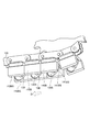
- the conceptual diagram of the multidirectional moving body module of the Example of this invention. The conceptual diagram which showed the some rotary body by the side of a moving surface in FIG.
- the multidirectional moving body module of the present invention includes a moving body module main body that moves on a moving surface, driving sprockets and driven members that are provided on the front and rear sides of the moving body module main body, and left and right driving drives.
- a pair of drive chains that are driven to freely move left and right independently while being wound around the sprocket and the driven member, and a rotary shaft that is rotatably disposed along the drive direction of the drive chain on the outer peripheral side of the drive chain.
- a plurality of rotating bodies each having an outer peripheral surface in contact with the moving surface, and fixed in a state of being arranged on the outer peripheral side of the drive chain, and can be brought into contact with each other according to a change in the posture of the drive chain.
- a plurality of chain bending restriction block bodies and the rotating shaft of the rotating body is inclined at a predetermined angle with respect to the driving direction of the driving chain.
- the inclination of the rotating shaft of the rotating body has a symmetrical relationship with the pair of left and right drive chains with respect to the front-rear direction line in the movable body module body, and the attitude of the driving chain is the driving sprocket and
- the opposed end faces in the chain longitudinal direction of the chain bending restricting block body are separated from each other in the chain longitudinal direction, and the posture of the drive chain is linear in the chain longitudinal direction.
- the opposite end faces of the chain bending restriction block body in the longitudinal direction of the chain are in contact with each other in the longitudinal direction of the chain, and the center of gravity and the moving surface side tend to make the steering mechanism complicated and the moving mechanism tend to be high.
- the load on the rotating body is reduced, the number of parts is reduced, and space is saved. Achieved, as long as it smoothly move and turn to obtain a sufficient driving force, aspects of the specific implementation may any be any one.
- the “pitch corresponding to the arrangement pitch of the plurality of rotating bodies” in the present invention means a regular interval as in the arrangement pitch of the plurality of rotating bodies. This is not limited to the case where it is equal to the arrangement pitch of the plurality of rotating bodies, and may be an integer multiple pitch of the arrangement pitch of the plurality of rotating bodies, or may be 1/2 pitch.
- the “side of the rotating body” in the present invention means at least one side of the rotating body along the width direction of the drive chain.
- the plurality of rotating bodies used in the present invention includes at least two rotating bodies adjacent to each other along the driving direction of the drive chain among the plurality of rotating bodies, and this set is periodically arranged at regular intervals. They may be arranged so as to realize the arranged state.
- the rotating bodies arranged in each of the pair of drive chains may be arranged in a staggered manner as a whole by arranging them in a staggered manner along the drive direction of the drive chain.
- a plurality of pairs of drive chains used in the present invention may be provided in the drive direction of the drive chain, or may be provided in the width direction of the drive chain.
- the driven member used in the present invention may be a driven sprocket having the same shape as the driving sprocket that drives the driving chain, or the driven member is rotated by the driving of the driving chain with the driving chain wound around the outer peripheral surface.
- a cylindrical member may be sufficient.
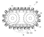
- driving the drive chain 120 in the forward direction means that the lower side portion, which is the moving surface side portion, which is the ground plane side portion of the drive chain 120, is driven in the backward direction B and the upper side of the drive chain 120.
- Driving the drive chain 120 in the reverse direction means driving the entire drive chain 120 in the reverse direction with respect to the normal direction described above.
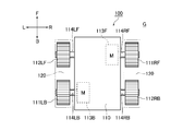
- the driving sprocket 111 and the driven member 112 provided on the front and rear of the mobile module main body 110 in order to distinguish the driving sprocket 111 and the driven member 112 provided on the front and rear of the mobile module main body 110 from the front and the rear, the driving sprocket 111 and the driven member 112 provided on the right and the front are used for driving.
- the sprocket 111RF and the driven member 112RB are used.
- the reference members 112 and the driving sprockets 111 provided on the left and right sides are replaced with reference numerals as the driven member 112LF and the driving sprocket 111LB.
- the multidirectional moving body module 100 includes a moving body module main body 110 that moves on the moving surface G, and driving sprockets provided on the left and right sides of the moving body module main body 110.
- 111RF, 111LB and driven members 112RB, 112LF are disposed on the driving sprocket 111RF
- the driving sprocket 111LB is disposed on the left rear side
- the driven member 112RB is disposed on the right rear side
- the driven member 112LF is disposed on the left front side.
- a pair of drive chains 120 and 120 that are driven to freely move forward and backward independently in a state of being wound around the drive sprocket 111RF and the driven member 112RB, and the drive sprocket 111LB and the driven member 112LF, respectively,
- a plurality of rotating bodies 130 that are rotatably disposed along the driving direction of the drive chain 120 on the outer peripheral side of the chain 120, have a rotating shaft 131, and contact the outer peripheral surface 130S with the moving surface G, respectively, and the drive chain 120
- Fixed base portions that are examples of a plurality of chain bending restricting block bodies that are fixed in a state in which they are arranged on the outer peripheral side of each other and that can be brought into contact with each other according to a change in the posture of the drive chain 120. 140A.
- the rotating shaft 131 of the rotating body 130 is inclined at a predetermined angle with respect to the driving direction of the driving chain 120, and the inclination of the rotating shaft 131 of the rotating body 130 is moved by the pair of left and right driving chains 120.
- the body module body 110 has a line-symmetric relationship with respect to the front-rear direction line. As a result, as will be described in detail later, the component force in the left-right direction is canceled and moved in the front-rear direction, or the component force in the left-right direction is reduced or increased to move in various directions.
- the multi-directional moving body module 100 can be rotated by generating a rotational moment with respect to the center of gravity C of the multi-directional moving body module 100.
- the opposite end surfaces 141AS and 141AS adjacent to each other in the longitudinal direction of the chain of the fixing base portion 140A are It is the structure which mutually contacts in the chain longitudinal direction.
- the chain portion of the drive chain 120 that is drawn out toward the moving surface G becomes a straight line, and one fixing pedestal portion 140A comes into contact with the adjacent fixing pedestal portion 140A in the chain longitudinal direction and is drawn out.
- the bending of the driving sprocket 111 and the driven member 112 in the chain portion to the opposite side to the side along the outer periphery is restricted.
- the bending from the endless outer periphery of the chain portion extended toward the moving surface G toward the inner periphery (the bending from the endless outer periphery indicated by the phantom line in FIG. 3 toward the inner periphery) is restricted.
- the wear of the drive chain 120 is suppressed, and the plurality of rotating bodies 130 are always in contact with the moving surface G to support the entire load, so that the load is dispersed and the load load per rotating body is reduced.
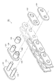
- the drive chain 120 includes an inner link unit formed by press-fitting a pair of front and rear bushes 124 to a pair of left and right inner plates 121, and an outer plate disposed outside the inner link unit. 122, a plurality of connecting pins 123 for press-fitting and fitting the inner link unit and the outer plate 122 in the longitudinal direction of the chain by being press-fitted to the outer plate 122, and a roller 125 loosely fitting a bush 124. Yes. Even if the drive chain 120 is not provided with the roller 125, there is no problem in its operation.
- the drive shaft 114RF and the drive shaft 114LB are configured to drive the drive chain 120 independently without being connected to each other.
- the driven shaft 114LF and the driven shaft 114RB are not connected to each other.
- the drive motor 113F drives the drive sprocket 111RF.
- power is transmitted by the drive chain 120, and the driven member 112RB is driven to rotate in accordance with the driving of the driving sprocket 111RF.
- the drive motor 113B drives the drive sprocket 111LB.
- power is transmitted by the drive chain 120, and the driven member 112LF is driven to rotate according to the drive of the drive sprocket 111LB. That is, the drive chains 120 and 120 arranged on the left and right in the drawing are driven independently of each other.
- both the front and rear drive motors 113F and 113B are arranged to balance the weight of the multidirectional driver module 100 and to secure a motor installation space. Is realized.
- the fixing base portion 140 ⁇ / b> A for fixing the rotating body 130 used in the multidirectional moving body module 100 to the drive chain 120 is an example of a chain bending restricting block body. Thereby, when the rotating body 130 is replaced, the fixing pedestal portion 140A can be replaced. That is, the multidirectional moving body module 100 is configured to reduce maintenance costs.
- the driving directions of the pair of driving chains 120 and 120 used in the multidirectional moving body module 100 are parallel to each other. As a result, the driving direction and driving speed of each of the pair of driving chains 120 and 120 are controlled so that the moving speed and the direction of the movable body module main body 110 can be adjusted. That is, the multidirectional moving body module 100 is configured to obtain a sufficient driving force by a simple drive control system and method, and to smoothly move and rotate in multiple directions.
- the rotation axis 131 ⁇ / b> A of the rotating body 130 provided on one of the pair of driving chains 120 and 120 used in the multidirectional moving body module 100 and the other of the pair of driving chains 120 and 120 are provided.
- the rotation axis 131A of the rotating body 130 intersects with each other. Specifically, the rotating shaft 131 of the rotating body 130 is inclined at a predetermined angle with respect to the driving direction of the driving chain 120, and the inclination of the rotating shaft 131 of the rotating body 130 is determined by a pair of left and right driving chains.
- Reference numeral 120 denotes a line-symmetric relationship with respect to the line in the front-rear direction in the mobile module main body 110.
- the multidirectional moving body module 100 is moved in the front-rear direction by canceling the left and right direction component forces, or the multidirectional moving body module 100 is moved in various directions by reducing or increasing the left and right direction component forces.
- the multi-directional mobile module 100 can be rotated by generating a rotational moment by shifting the force acting line with respect to the center of gravity C of the multi-directional mobile module 100.
- the rotation axis 131 ⁇ / b> A of the rotating body 130 provided on one of the pair of driving chains 120, 120 used in the multidirectional moving body module 100 is inclined by 45 ° with respect to the driving direction of the driving chain 120. Yes.
- the rotation axis 131 ⁇ / b> A of the rotating body 130 provided on the other side is inclined by 45 ° with respect to the drive direction of the drive chain 120.
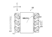
- FIGS. 1 to 13B For convenience of explanation, the forward direction F, the backward direction B, the right R, and the left L of the multidirectional moving body module 100 are indicated by arrows in FIGS. 1, 5 to 13B.
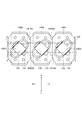
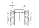
- the white arrows D (DR1, DR2,..., DL1, DL2,...) Shown in FIGS. 1, 3A, 7A to 13A are on the moving surface G side of the drive chain 120 having an endless endless track. It is the velocity vector of the lower part facing.
- This velocity vector is based on the multidirectional moving body module 100. More specifically, for example, the speed vector D of the lower portion of the drive chain 120 shown in FIG. 1 facing the moving surface G is equal to the speed vectors DR1 and DL1 of the drive chain 120 shown in FIG. 7A. I'm doing it.
- the moving direction of the multidirectional moving body module 100 shown below is an example, and the multidirectional moving body module 100 moves by changing the combination of the magnitudes and directions of the respective velocity vectors of the pair of drive chains 120 and 120. It can move in various directions within the plane G.
- FIG. 7A and 7B show the case where the speed vector DR1 of the right drive chain 120 and the speed vector DL1 of the left drive chain 120 have the same magnitude and their directions are the backward direction B.
- the acting force vectors FR1 and FL1 act from the outer peripheral surface 130S of each rotating body 130 to the moving surface G.
- the acting force vector FR1 is a vector that acts on the moving surface G from the outer peripheral surface 130S of the rotating body 130 of the right drive chain 120.
- the acting force vector FL1 is a vector acting from the outer peripheral surface 130S of the rotating body 130 of the left drive chain 120 to the moving surface G.
- the rotation shaft 131 of the rotating body 130 of the right drive chain 120 is inclined 45 ° with respect to the drive direction while the right side is inclined backward and the left side is inclined forward.
- the direction of the speed vector DR1 of the right drive chain 120 is the backward direction B. Accordingly, as shown in FIGS. 7A and 7B, the acting force vector FR1 is directed from the left front to the right rear while being inclined by 45 ° with respect to the driving direction.
- the rotation shaft 131 of the rotating body 130 of the left drive chain 120 is inclined 45 ° with respect to the drive direction while the right side is inclined forward and the left side is inclined backward.
- the direction of the speed vector DL1 of the left drive chain 120 is the backward direction B. Accordingly, as shown in FIGS. 7A and 7B, the acting force vector FL1 is directed from the right front to the left rear while being inclined by 45 ° with respect to the driving direction.
- the component force of the acting force vector FR1 in the left-right direction and the component force of the acting force vector FL1 in the left-right direction are equal, the directions are opposite to each other, and are on the same line.
- the rightward leftward component of FR1 and the leftward leftward component of action force vector FL1 cancel each other.
- the component force of the action force vector FR1 in the front-rear direction and the component force of the action force vector FL1 in the front-rear direction are the same, and the directions are the same.
- the position is symmetrical with respect to the center of gravity C of the multidirectional moving body module 100.
- the direction of the resultant force vector FA1 which is the sum of the acting force vector FR1 and the acting force vector FL1 is the backward direction B, and the center of gravity C of the multidirectional mobile module 100 is located on the line of the resultant force vector FA1.
- the direction of the reaction force FB1 acting on the moving body module 100 from the moving surface G is the forward direction F
- the center of gravity C of the multidirectional moving body module 100 is positioned on the line of the reaction force FB1. That is, no moment of force (rotational force) is generated. For this reason, the multidirectional moving body module 100 moves in the forward direction F.
- FIG. 8A and 8B show a case where the speed vector DR2 of the right drive chain 120 and the speed vector DL2 of the left drive chain 120 have the same magnitude and their directions are the forward direction F.
- the acting force vectors FR2 and FL2 act from the outer peripheral surface 130S of each rotating body 130 to the moving surface G.
- the acting force vector FR2 is a vector acting from the outer peripheral surface 130S of the rotating body 130 of the right drive chain 120 to the moving surface G.
- the acting force vector FL2 is a vector acting from the outer peripheral surface 130S of the rotating body 130 of the left drive chain 120 to the moving surface G.
- the rotation shaft 131 of the rotating body 130 of the right drive chain 120 is inclined 45 ° with respect to the drive direction while the right side is inclined backward and the left side is inclined forward.
- the direction of the speed vector DR2 of the right drive chain 120 is the forward direction F. Therefore, as shown in FIGS. 8A and 8B, the acting force vector FR2 is directed from the right rear to the left front in a state inclined by 45 ° with respect to the driving direction.
- the rotation shaft 131 of the rotating body 130 of the left drive chain 120 is inclined 45 ° with respect to the drive direction while the right side is inclined forward and the left side is inclined backward.
- the direction of the speed vector DL2 of the left drive chain 120 is the forward direction F. Accordingly, as shown in FIGS. 8A and 8B, the acting force vector FL2 is directed from the rear left to the front right while being inclined by 45 ° with respect to the driving direction.
- the directions are opposite to each other, and are on the same line, the acting vector The left-right direction component force of FR2 and the right-left direction component force of action force vector FL2 cancel each other.
- the force component FR2 in the front-rear direction and the force component FL2 in the front-rear direction have the same magnitude, the directions are the same, and the action line of the force component in the front-rear direction The position is symmetrical with respect to the center of gravity C of the multidirectional moving body module 100.
- the direction of the resultant force vector FA2 which is the sum of the acting force vector FR2 and the acting force vector FL2, is the forward direction F
- the center of gravity C of the multidirectional moving body module 100 is located on the line of the resultant force vector FA2.
- the direction of the reaction force FB2 acting on the moving body module 100 from the moving surface G is the backward direction B
- the center of gravity C of the multidirectional moving body module 100 is located on the line of the reaction force FB2. That is, no moment of force (rotational force) is generated. For this reason, the multidirectional moving body module 100 moves in the backward direction B.
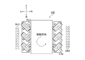
- the acting force vectors FR3 and FL3 act from the outer peripheral surface 130S of each rotating body 130 to the moving surface G.
- the acting force vector FR3 is a vector acting from the outer peripheral surface 130S of the rotating body 130 of the right drive chain 120 to the moving surface G.
- the acting force vector FL3 is a vector acting from the outer peripheral surface 130S of the rotating body 130 of the left drive chain 120 to the moving surface G.
- the rotation shaft 131 of the rotating body 130 of the right drive chain 120 is inclined 45 ° with respect to the drive direction while the right side is inclined backward and the left side is inclined forward.
- the direction of the speed vector DR3 of the right drive chain 120 is the backward direction B. Therefore, as shown in FIGS. 9A and 9B, the acting force vector FR3 is directed from the left front to the right rear while being inclined by 45 ° with respect to the driving direction.
- the rotation shaft 131 of the rotating body 130 of the left drive chain 120 is inclined 45 ° with respect to the drive direction while the right side is inclined forward and the left side is inclined backward.
- the direction of the speed vector DL3 of the left drive chain 120 is the forward direction F. Therefore, as shown in FIGS. 9A and 9B, the acting force vector FL3 is directed from the rear left to the front right while being inclined by 45 ° with respect to the driving direction.
- the direction of the component force of the acting force vector FR3 in the right and left direction and the direction of the component force of the acting force vector FL3 in the right and left direction are the same, so they are not canceled out.
- the position of the action line of the translational resultant force vector FA3S which is the sum of the rightward and leftward component force of the acting force vector FR3 and the rightward and leftward component force of the acting force vector FL3, is the center of gravity C of the multidirectional mobile module 100.
- the direction of the translational resultant force vector FA3S is rightward with respect to the multidirectional moving body module 100.
- the position of the line of action of the translational reaction force FB3S acting on the moving body module 100 from the moving surface G becomes a position passing through the center of gravity C of the multidirectional moving body module 100, and the direction of the translational reaction force FB3S is The left direction is based on the multidirectional moving body module 100.
- the component force of the action force vector FR3 in the front-rear direction and the component force of the action force vector FL3 in the front-rear direction are equal and opposite in direction, but the action line of the force component in the front-rear direction is Since the position is away from the center of gravity C of the multidirectional moving body module 100, the component force in the front-rear direction is not canceled out, and a moment (rotational force) in the clockwise direction in FIGS. 9A and 9B is generated.
- the position of the action line of the rotational resultant force vector FA3R which is the sum of the component force of the action force vector FR3 in the front-rear direction and the force component of the action force vector FL3 in the front-rear direction, is the multidirectional mobile module 100.
- the direction of the rotational resultant vector FA3R is clockwise with respect to the center of gravity C of the multidirectional moving body module 100. Accordingly, the position of the line of action of the rotational reaction force FB3R acting on the moving body module 100 from the moving surface G is away from the center of gravity C of the multidirectional moving body module 100, and the direction of the rotational reaction force FB3R is The counterclockwise direction is based on the center of gravity C of the direction moving body module 100.
- the multidirectional moving body module 100 moves to the left with respect to the moving plane G with respect to the moving surface G while rotating counterclockwise by the translational reaction force FB3S and the rotational reaction force FB3R.
- the movement is a combination of translation and rotation.
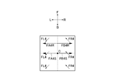
- 10A and 10B show that the speed vector DR4 of the right drive chain 120 and the speed vector DL4 of the left drive chain 120 are equal in magnitude, the direction of the speed vector DR4 is the forward direction F, and the speed This is a case where the direction of the vector DL4 is the backward direction B.
- acting force vectors FR4 and FL4 act from the outer peripheral surface 130S of each rotating body 130 to the moving surface G.
- the acting force vector FR4 is a vector that acts on the moving surface G from the outer peripheral surface 130S of the rotating body 130 of the right drive chain 120.
- the acting force vector FL4 is a vector acting from the outer peripheral surface 130S of the rotating body 130 of the left drive chain 120 to the moving surface G.
- the rotation shaft 131 of the rotating body 130 of the right drive chain 120 is inclined 45 ° with respect to the drive direction while the right side is inclined backward and the left side is inclined forward.
- the direction of the speed vector DR4 of the right drive chain 120 is the forward direction F. Accordingly, as shown in FIGS. 10A and 10B, the acting force vector FR4 is directed from the right rear to the left front in a state inclined by 45 ° with respect to the driving direction.
- the rotation shaft 131 of the rotating body 130 of the left drive chain 120 is inclined 45 ° with respect to the drive direction while the right side is inclined forward and the left side is inclined backward.
- the direction of the speed vector DL4 of the left drive chain 120 is the backward direction B. Therefore, as shown in FIGS. 10A and 10B, the acting force vector FL4 is directed from the front right to the rear left while being inclined by 45 ° with respect to the driving direction.
- the position of the action line of the translational resultant force vector FA4S which is the sum of the left and right component of the acting force vector FR4 and the right and left component of the acting force vector FL4, is the center of gravity C of the multidirectional mobile module 100.
- the direction of the translational resultant force vector FA4S is leftward with respect to the multidirectional moving body module 100.
- the position of the line of translation reaction force FB4S acting on the moving body module 100 from the moving surface G becomes a position passing through the center of gravity C of the multidirectional moving body module 100, and the direction of the translation reaction force FB4S is It turns to the right with respect to the multidirectional moving body module 100.
- the magnitude of the forward and backward component force of the acting force vector FR4 is equal to the magnitude of the backward and forward component force of the acting force vector FL4 and the directions are opposite to each other. Since the position is away from the center of gravity C of the multidirectional moving body module 100, the component force in the front-rear direction is not canceled out, and a counterclockwise force moment (rotational force) in FIGS. 10A and 10B is generated.
- the position of the action line of the rotational resultant force vector FA4R which is the sum of the component force forward of the acting force vector FR4 and the component force forward of the acting force vector FL4 in the front-and-rear direction, is the multidirectional mobile module 100.
- the direction of the rotational resultant vector FA4R is counterclockwise with respect to the center of gravity C of the multidirectional moving body module 100. Accordingly, the position of the line of action of the rotational reaction force FB4R acting on the moving body module 100 from the moving surface G is away from the center of gravity C of the multidirectional moving body module 100, and the direction of the rotational reaction force FB4R is many.
- the clockwise direction is based on the center of gravity C of the direction moving body module 100.
- the multidirectional moving body module 100 moves to the right with respect to the moving plane G with respect to the moving plane G while rotating clockwise by the translational reaction force FB4S and the rotational reaction force FB4R.
- the movement is a combination of translation and rotation.
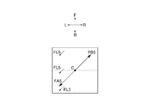
- FIG. 11A and FIG. 11B show that the speed vector DL5 of the right drive chain 120 which is one of the pair is zero, and the speed vector DL5 of the left drive chain 120 which is the other is zero. This is the case when the direction is larger and the direction is the backward direction B. In this case, the acting force vector FL5 acts from the outer peripheral surface 130S of the rotating body 130 of the left drive chain 120 to the moving surface G.
- the rotation shaft 131 of the rotating body 130 of the left drive chain 120 is inclined 45 ° with respect to the drive direction while the right side is inclined forward and the left side is inclined backward.
- the direction of the speed vector DL5 of the left drive chain 120 is the backward direction B. Accordingly, as shown in FIGS. 11A and 11B, the acting force vector FL5 is directed from the right front to the left rear in a state inclined by 45 ° with respect to the driving direction.
- the rotation shaft 131 of the rotating body 130 of the right drive chain 120 is inclined at 45 ° with respect to the drive direction while the right side is inclined backward and the left side is inclined forward.
- the rotating body 130 provided on the right drive chain 120 acts so as to release the acting force vector FL5.
- the direction of the resultant force vector FA5 that is the sum of the respective acting force vectors FL5 is the same as the acting force vector FL5. In other words, the direction is from front right to rear left with a 45 ° tilt with respect to the driving direction.
- the center of gravity C of the multidirectional moving body module 100 When the center of gravity C of the multidirectional moving body module 100 is located on the action line of the resultant vector FA5, the direction of the reaction force FB5 acting on the moving body module 100 from the moving surface G is inclined by 45 ° with respect to the driving direction. The direction is from left rear to right front. Furthermore, the center of gravity C of the multidirectional moving body module 100 is also located on the line of action of the reaction force FB5. That is, no moment of force (rotational force) is generated. For this reason, the multidirectional moving body module 100 moves (translates) in the direction of 45 ° diagonally right frontward.
- the direction of the reaction force FB5 is tilted by 45 ° with respect to the driving direction from left rear to right front.
- the position of the action line of the reaction force FB5 is also away from the center of gravity C of the multidirectional moving body module 100. That is, a moment of force (rotational force) is generated. Since the rotational motion and the translation motion are combined, the multidirectional moving body module 100 moves while bending in a predetermined direction.
- the multidirectional moving body module 100 bends clockwise while proceeding diagonally forward to the right.
- the multidirectional mobile module 100 bends counterclockwise while proceeding diagonally forward to the right.
- 12A and 12B show that the speed vector DR6 of the right drive chain 120 as one of the pair is larger than zero and smaller than the speed vector DL6 of the left drive chain 120 as the other.
- the direction of the velocity vector DR6 is the forward direction F
- the direction of the velocity vector DL6 is the backward direction B.
- the acting force vectors FR6 and FL6 act from the outer peripheral surface 130S of each rotating body 130 to the moving surface G.
- the acting force vector FR6 is a vector that acts on the moving surface G from the outer peripheral surface 130S of the rotating body 130 of the right drive chain 120.
- the acting force vector FL6 is a vector that acts on the moving surface G from the outer peripheral surface 130S of the rotating body 130 of the left drive chain 120.
- the rotation shaft 131 of the rotating body 130 of the right drive chain 120 is inclined 45 ° with respect to the drive direction while the right side is inclined backward and the left side is inclined forward.
- the direction of the speed vector DR6 of the right drive chain 120 is the forward direction F. Therefore, as shown in FIGS. 12A and 12B, the acting force vector FR6 is directed from the right rear to the left front in a state inclined by 45 ° with respect to the driving direction.
- the rotation shaft 131 of the rotating body 130 of the left drive chain 120 is inclined 45 ° with respect to the drive direction while the right side is inclined forward and the left side is inclined backward.
- the direction of the speed vector DL6 of the left drive chain 120 is the backward direction B. Accordingly, as shown in FIGS. 12A and 12B, the acting force vector FL6 is directed from the right front to the left rear while being inclined by 45 ° with respect to the driving direction.
- the position of the action line of the translational resultant force vector FA6S which is the sum of the left and right component of the acting force vector FR6 and the right and left component of the acting force vector FL6, is the center of gravity C of the multidirectional mobile module 100.
- the direction of the translational resultant force vector FA6S is leftward with respect to the multidirectional moving body module 100.
- the position of the action line of the translational reaction force FB6S acting on the moving body module 100 from the moving surface G becomes a position passing through the center of gravity C of the multidirectional moving body module 100, and the direction of the translational reaction force FB6S is It turns to the right with respect to the multidirectional moving body module 100.
- the position of the action line of the rotational resultant force vector FA6R which is the sum of the forward and backward component forces of the acting force vector FR6 and the backward and forward force components of the acting force vector FL6, is the multidirectional mobile module 100.
- the direction of the rotational resultant vector FA6R is counterclockwise with reference to the center of gravity C of the multidirectional moving body module 100.
- the position of the action line of the rotational reaction force FB6R acting on the moving body module 100 from the moving surface G is away from the center of gravity C of the multidirectional moving body module 100, and the direction of the rotational reaction force FB6R is many.
- the clockwise direction is based on the center of gravity C of the direction moving body module 100.
- the multidirectional moving body module 100 moves to the right with respect to the moving plane G with respect to the moving plane G while rotating clockwise by the translational reaction force FB6S and the rotational reaction force FB6R.
- the acting force vector FL6 is the same as the magnitude of the backward force in the front-rear direction of the acting force vector FL4 in the case shown in FIGS. 10A and 10B, the acting force vector The magnitude of the forward force in the front-rear direction of FR6 is smaller than the magnitude of the forward force in the front-rear direction of the acting force vector FR4 in the case shown in FIGS. 10A and 10B.
- the magnitude of the rotational reaction force FB6R shown in FIGS. 12A and 12B is smaller than the magnitude of the rotational reaction force FB4R shown in FIGS. 10A and 10B.
- the left side of the multi-directional moving body module 100 moves backward with the right side as a fulcrum. Try to move forward more than the right travel distance. That is, the multidirectional moving body module 100 bends clockwise while proceeding diagonally forward to the right.
- FIG. 13A and FIG. 13B show that the speed vector DR7 of the right drive chain 120 which is one of the pair is larger than zero and smaller than the speed vector DL7 which is the other left side. Is the backward direction B, and the direction of the velocity vector DL7 is the backward direction B.
- the acting force vectors FR7 and FL7 act from the outer peripheral surface 130S of each rotating body 130 to the moving surface G.
- the acting force vector FR7 is a vector acting from the outer peripheral surface 130S of the rotating body 130 of the right drive chain 120 to the moving surface G.
- the acting force vector FL7 is a vector that acts on the moving surface G from the outer peripheral surface 130S of the rotating body 130 of the left drive chain 120.
- the rotation shaft 131 of the rotating body 130 of the right drive chain 120 is inclined 45 ° with respect to the drive direction while the right side is inclined backward and the left side is inclined forward.
- the direction of the speed vector DR7 of the right drive chain 120 is the backward direction B. Therefore, as shown in FIGS. 13A and 13B, the acting force vector FR7 is directed from the left front to the right rear while being inclined by 45 ° with respect to the driving direction.
- the rotation shaft 131 of the rotating body 130 of the left drive chain 120 is inclined 45 ° with respect to the drive direction while the right side is inclined forward and the left side is inclined backward.
- the direction of the speed vector DL7 of the left drive chain 120 is the backward direction B. Accordingly, as shown in FIGS. 13A and 13B, the acting force vector FL7 is directed from the right front to the left rear while being inclined by 45 ° with respect to the driving direction.
- the magnitudes of the rightward and leftward component forces of the acting force vector FR7 and the leftward and rightward component forces of the acting force vector FL7 are not equal, the directions are opposite to each other and are on the same line.
- the left-right component of force vector FL7 is reduced by the right-left component of action vector FR7.
- the position of the action line of the left-right translational resultant force vector which is the sum of the left-right component of the acting force vector FR7 and the right-left component of the acting force vector FL7, is the center of gravity of the multidirectional mobile module 100.
- the direction of the translational force vector in the left-right direction is leftward with respect to the multidirectional moving body module 100.
- the direction of the force component FR7 in the front-rear direction and the component force in the front-rear direction of the force vector FL7 are the same, but the magnitudes are not equal to each other, and the action of the force component in the front-rear direction Since the position of the line is away from the center of gravity C of the multidirectional moving body module 100 but is in a laterally symmetrical positional relationship, the longitudinal translational resultant force vector that translates backward in the longitudinal direction and the counterclockwise rotation in FIGS. 13A and 13B A moment of force (rotational force) is generated.
- the translational force vector in the front-rear direction includes a component force that acts backward in the front-rear direction of the acting force vector FR7, and a component force that acts backward in the front-rear direction of the acting force vector FR7 among the component forces in the rearward direction in the acting force vector FL7. It is the sum of the same size.
- the magnitude of the resultant rotational force vector FA7R which is a moment of force (rotational force) is the difference between the magnitude of the backward force in the front-rear direction of the action force vector FL7 and the magnitude of the force in the rearward direction of the action force vector FR7. It is. Further, the position of the line of action of the rotational resultant vector FA7R is away from the center of gravity C of the multidirectional moving body module 100, and the direction of the rotational resultant vector FA7R is counterclockwise with respect to the center of gravity C of the multidirectional moving body module 100. It becomes the turning direction.
- the position of the line of action of the rotational reaction force FB7R acting on the moving body module 100 from the moving surface G is away from the center of gravity C of the multidirectional moving body module 100, and the direction of the rotational reaction force FB7R is many.
- the clockwise direction is based on the center of gravity C of the direction moving body module 100.
- the position of the action line of the translational resultant force vector FA7S which is the sum of the lateral translational force vector and the longitudinal translational force vector, becomes a position passing through the center of gravity C of the multidirectional mobile module 100, and the translational resultant force vector FA7S.
- the direction is a diagonally backward left direction with respect to the multi-directional moving body module 100. Accordingly, the position of the action line of the translation reaction force FB7S acting on the moving body module 100 from the moving surface G becomes a position passing through the center of gravity C of the multidirectional moving body module 100, and the direction of the translation reaction force FB7S is It becomes the diagonally forward right direction with respect to the multidirectional moving body module 100.
- the multi-directional moving body module 100 moves to the right front side with respect to the moving plane G with respect to the moving surface G while rotating clockwise by the translational reaction force FB7S and the rotational reaction force FB7R. . That is, the multidirectional moving body module 100 bends in a clockwise direction while proceeding diagonally forward to the right, which is largely closer to the front than in the case illustrated in FIG. 12A.
- the multi-directional moving body module 100 of the present embodiment obtained in this way includes a moving body module main body 110 that moves on the moving surface G, and a driving module provided at the front and rear of each of the left and right sides of the moving body module main body 110.
- a fixed pedestal portion 140A which is a block body for restricting chain bending, in which the opposing end surfaces 141AS and 141AS can be brought into contact with each other in accordance with a change in the posture of the drive chain 120.
- the drive shaft 120 is inclined at a predetermined angle with respect to the drive direction of the drive chain 120, and the tilt of the rotary shaft 131 of the rotary body 130 is determined by the pair of left and right drive chains 120, 120 in the front-rear direction of the mobile module main body 110.
- the attitude of the drive chain 120 is bent along the outer circumferences of the drive sprocket 111 and the driven member 112
- the fixed base portion 140A is adjacent to each other in the longitudinal direction of the chain.
- the end surfaces 141AS and 141AS are separated from each other in the longitudinal direction of the chain, and the posture of the drive chain 120 is the chain.
- the multidirectional moving body module of the present modification is different only in that the wall-like block body 140B is used in place of the fixing base portion 140A as the above-described chain bending restriction block body. Parts common to the mobile module 100 are denoted by common reference numerals, and detailed description thereof is omitted.
- the chain longitudinal direction outer side surface 142BS of the pair of wall-like block bodies 140B and 140B installed on the side of the rotating body 130 used in the multidirectional moving body module of the present modification is It is formed closer to the inner periphery of the drive chain 120 than the contact line 130L that contacts the moving surface G on the outer peripheral surface 130S of the rotating body 130.
- the location where the bending of the drive chain 120 is restricted is the side of the rotating body 130 where the lever ratio becomes small far from the so-called chain bending fulcrum.
- the chain bending restricting block body is composed of a pair of wall-like block bodies 140B and 140B installed on the side of the rotating body 130.
- the chain longitudinal direction outer side surface 142BS of the wall-shaped block body 140B is formed closer to the inner periphery of the drive chain 120 than the contact line 130L contacting the moving surface G of the outer peripheral surface 130S of the rotating body 130.
- Multi-directional moving body module 110 ... Moving body module main body 111, 111RF, 111LB ... Drive sprocket 112, 112RB, 112LF ... Driven member 113F, 113B ... Drive motor 114RF, 1414LB .... Drive shafts 114RB, 114LF ... Driven shaft 120 ... Drive chain 130 ... Rotating body 130L ... Contact line in contact with the moving surface 130S ... Outer peripheral surface of the rotating body 131 ...
Landscapes
- Engineering & Computer Science (AREA)
- Chemical & Material Sciences (AREA)
- Combustion & Propulsion (AREA)
- Transportation (AREA)
- Mechanical Engineering (AREA)
- Toys (AREA)
Applications Claiming Priority (2)
| Application Number | Priority Date | Filing Date | Title |
|---|---|---|---|
| JP2012064221 | 2012-03-21 | ||
| JP2012-064221 | 2012-03-21 |
Publications (1)
| Publication Number | Publication Date |
|---|---|
| WO2013141017A1 true WO2013141017A1 (fr) | 2013-09-26 |
Family
ID=49222479
Family Applications (1)
| Application Number | Title | Priority Date | Filing Date |
|---|---|---|---|
| PCT/JP2013/055995 Ceased WO2013141017A1 (fr) | 2012-03-21 | 2013-03-05 | Module d'objet mobile multidirectionnel |
Country Status (1)
| Country | Link |
|---|---|
| WO (1) | WO2013141017A1 (fr) |
Cited By (3)
| Publication number | Priority date | Publication date | Assignee | Title |
|---|---|---|---|---|
| WO2016012592A1 (fr) * | 2014-07-25 | 2016-01-28 | Pasquato Gaetano | Chenille dotée d'une flexibilité structurellement limitée pour véhicules terrestres |
| CN106627823A (zh) * | 2016-12-06 | 2017-05-10 | 哈工大机器人集团上海有限公司 | 一种全向运动的机器人传动履带 |
| KR102451381B1 (ko) * | 2021-06-29 | 2022-10-06 | 충남대학교산학협력단 | 이동로봇의 횡방향 이동 장치 |
Citations (5)
| Publication number | Priority date | Publication date | Assignee | Title |
|---|---|---|---|---|
| JPS526336U (fr) * | 1975-06-30 | 1977-01-17 | ||
| JPS60173476U (ja) * | 1984-04-25 | 1985-11-16 | 株式会社神戸製鋼所 | クロ−ラシユ− |
| JPH0664567A (ja) * | 1992-08-19 | 1994-03-08 | Kansai Electric Power Co Inc:The | 履帯式走行体および履帯式走行装置 |
| JPH1143082A (ja) * | 1997-07-30 | 1999-02-16 | Matsuda Plantec Kk | 全方向移動装置 |
| JP2004344435A (ja) * | 2003-05-22 | 2004-12-09 | Japan Science & Technology Agency | パワーアシスト型移動台車 |
-
2013
- 2013-03-05 WO PCT/JP2013/055995 patent/WO2013141017A1/fr not_active Ceased
Patent Citations (5)
| Publication number | Priority date | Publication date | Assignee | Title |
|---|---|---|---|---|
| JPS526336U (fr) * | 1975-06-30 | 1977-01-17 | ||
| JPS60173476U (ja) * | 1984-04-25 | 1985-11-16 | 株式会社神戸製鋼所 | クロ−ラシユ− |
| JPH0664567A (ja) * | 1992-08-19 | 1994-03-08 | Kansai Electric Power Co Inc:The | 履帯式走行体および履帯式走行装置 |
| JPH1143082A (ja) * | 1997-07-30 | 1999-02-16 | Matsuda Plantec Kk | 全方向移動装置 |
| JP2004344435A (ja) * | 2003-05-22 | 2004-12-09 | Japan Science & Technology Agency | パワーアシスト型移動台車 |
Cited By (3)
| Publication number | Priority date | Publication date | Assignee | Title |
|---|---|---|---|---|
| WO2016012592A1 (fr) * | 2014-07-25 | 2016-01-28 | Pasquato Gaetano | Chenille dotée d'une flexibilité structurellement limitée pour véhicules terrestres |
| CN106627823A (zh) * | 2016-12-06 | 2017-05-10 | 哈工大机器人集团上海有限公司 | 一种全向运动的机器人传动履带 |
| KR102451381B1 (ko) * | 2021-06-29 | 2022-10-06 | 충남대학교산학협력단 | 이동로봇의 횡방향 이동 장치 |
Similar Documents
| Publication | Publication Date | Title |
|---|---|---|
| US6179073B1 (en) | Hybrid track for a vehicle | |
| JP2014196004A (ja) | 多方向移動体モジュール | |
| EP3597575B1 (fr) | Module de guidage et dispositif d'entraînement comportant celui-ci | |
| US20070137905A1 (en) | Traveling robot | |
| JP7591459B2 (ja) | 走行車 | |
| JP4759323B2 (ja) | クローラ型走行装置 | |
| WO2013141017A1 (fr) | Module d'objet mobile multidirectionnel | |
| TW201915629A (zh) | 移動裝置與移動系統 | |
| WO2013022017A1 (fr) | Module de corps mobile dans des directions multiples | |
| US8678408B2 (en) | Travel device for transport vehicle | |
| CA3013730C (fr) | Suspension et vehicule de type a selle, motoneige et vehicule tout-terrain equipe de la suspension | |
| KR102451381B1 (ko) | 이동로봇의 횡방향 이동 장치 | |
| JP6223278B2 (ja) | クローラ走行装置 | |
| CN101327887A (zh) | 用于垂直电梯的驱动装置 | |
| KR102597420B1 (ko) | 모듈형 듀얼 스위블 휠 및 이를 포함하는 플랫폼 | |
| JP2013193614A (ja) | 多方向移動体モジュール | |
| KR20170086252A (ko) | 전방향 무한궤도 벨트 장치 | |
| US11090998B2 (en) | Vehicle including a first axle beam and a second axle beam coupled together via a link | |
| JP2020172207A (ja) | 履帯駆動車両 | |
| CN213165376U (zh) | 一种轻载的轨道机器人快拆式运动装置 | |
| CN108016518A (zh) | 一种新式麦轮履带车 | |
| WO2013022013A1 (fr) | Module de corps mobile dans plusieurs directions | |
| KR101986448B1 (ko) | 볼타이어 구동 시스템 | |
| JP6106348B2 (ja) | 全方向移動車両 | |
| KR20160115454A (ko) | 전방향 휠 구조체 |
Legal Events
| Date | Code | Title | Description |
|---|---|---|---|
| 121 | Ep: the epo has been informed by wipo that ep was designated in this application |
Ref document number: 13764861 Country of ref document: EP Kind code of ref document: A1 |
|
| NENP | Non-entry into the national phase |
Ref country code: DE |
|
| 122 | Ep: pct application non-entry in european phase |
Ref document number: 13764861 Country of ref document: EP Kind code of ref document: A1 |
|
| NENP | Non-entry into the national phase |
Ref country code: JP |