WO2013141070A1 - Filtre à air pour appareil de dépôt chimique en phase vapeur et appareil de dépôt chimique en phase vapeur équipé de celui-ci - Google Patents
Filtre à air pour appareil de dépôt chimique en phase vapeur et appareil de dépôt chimique en phase vapeur équipé de celui-ci Download PDFInfo
- Publication number
- WO2013141070A1 WO2013141070A1 PCT/JP2013/056731 JP2013056731W WO2013141070A1 WO 2013141070 A1 WO2013141070 A1 WO 2013141070A1 JP 2013056731 W JP2013056731 W JP 2013056731W WO 2013141070 A1 WO2013141070 A1 WO 2013141070A1
- Authority
- WO
- WIPO (PCT)
- Prior art keywords
- cvd apparatus
- filter medium
- medium layer
- air filter
- filter
- Prior art date
- Legal status (The legal status is an assumption and is not a legal conclusion. Google has not performed a legal analysis and makes no representation as to the accuracy of the status listed.)
- Ceased
Links
Images


Classifications
-
- B—PERFORMING OPERATIONS; TRANSPORTING
- B01—PHYSICAL OR CHEMICAL PROCESSES OR APPARATUS IN GENERAL
- B01D—SEPARATION
- B01D39/00—Filtering material for liquid or gaseous fluids
- B01D39/14—Other self-supporting filtering material ; Other filtering material
- B01D39/16—Other self-supporting filtering material ; Other filtering material of organic material, e.g. synthetic fibres
- B01D39/1607—Other self-supporting filtering material ; Other filtering material of organic material, e.g. synthetic fibres the material being fibrous
- B01D39/1623—Other self-supporting filtering material ; Other filtering material of organic material, e.g. synthetic fibres the material being fibrous of synthetic origin
-
- C—CHEMISTRY; METALLURGY
- C23—COATING METALLIC MATERIAL; COATING MATERIAL WITH METALLIC MATERIAL; CHEMICAL SURFACE TREATMENT; DIFFUSION TREATMENT OF METALLIC MATERIAL; COATING BY VACUUM EVAPORATION, BY SPUTTERING, BY ION IMPLANTATION OR BY CHEMICAL VAPOUR DEPOSITION, IN GENERAL; INHIBITING CORROSION OF METALLIC MATERIAL OR INCRUSTATION IN GENERAL
- C23C—COATING METALLIC MATERIAL; COATING MATERIAL WITH METALLIC MATERIAL; SURFACE TREATMENT OF METALLIC MATERIAL BY DIFFUSION INTO THE SURFACE, BY CHEMICAL CONVERSION OR SUBSTITUTION; COATING BY VACUUM EVAPORATION, BY SPUTTERING, BY ION IMPLANTATION OR BY CHEMICAL VAPOUR DEPOSITION, IN GENERAL
- C23C16/00—Chemical coating by decomposition of gaseous compounds, without leaving reaction products of surface material in the coating, i.e. chemical vapour deposition [CVD] processes
- C23C16/44—Chemical coating by decomposition of gaseous compounds, without leaving reaction products of surface material in the coating, i.e. chemical vapour deposition [CVD] processes characterised by the method of coating
- C23C16/4401—Means for minimising impurities, e.g. dust, moisture or residual gas, in the reaction chamber
- C23C16/4402—Reduction of impurities in the source gas
-
- B—PERFORMING OPERATIONS; TRANSPORTING
- B01—PHYSICAL OR CHEMICAL PROCESSES OR APPARATUS IN GENERAL
- B01D—SEPARATION
- B01D2239/00—Aspects relating to filtering material for liquid or gaseous fluids
- B01D2239/12—Special parameters characterising the filtering material
- B01D2239/1233—Fibre diameter
Definitions
- the present invention relates to an air filter used in a CVD apparatus (air filter for CVD apparatus) and a CVD apparatus having the same.
- the air filter is used to collect (capture) fine particles contained in air, source gas or exhaust gas, and has a high particle capture rate (capability of collecting particles with high efficiency) and pressure loss. Low is required.
- the materials that make up the air filter also vary widely depending on the application.
- Fluorine resin such as polytetrafluoroethylene (PTFE) is known as a material constituting the air filter. Since fluororesins have excellent properties (chemical resistance, plasma resistance, heat resistance, etc.), fluororesin air filters are used in a wide range of applications.
- PTFE polytetrafluoroethylene
- Patent Document 1 discloses a turbine air inlet filter including a composite filter medium and a frame.
- the composite filter medium includes a membrane filter layer containing porous polytetrafluoroethylene (expanded PTFE) and a depth filter medium layer. Comprising.
- Patent Document 2 discloses a filter medium including a PTFE porous membrane (stretched PTFE) obtained by stretching unsintered PTFE under specific conditions.
- Patent Document 3 an PTFE powder is dispersed in a matrix (e.g., viscose) to prepare an aqueous dispersion, and the aqueous dispersion is discharged into a coagulation bath and spun to produce an unstretched PTFE fiber sheet.
- a fluorine fiber thin sheet used for filter applications is disclosed, which is produced by heating and sintering an unstretched PTFE fiber sheet and stretching it at least in the longitudinal direction or the transverse direction.
- Patent Document 4 a raw material for paper making of a fluoro fiber is dehydrated and dried by a wet paper making method using a wire netting die to form a forming raw material, and the forming raw material is subjected to the heat treatment after the forming raw material.
- a fluorine fiber molded article used for a filter which is obtained by inserting the preform into a mold and hot pressing.
- Such a filter made of a fluorine fiber cannot balance pressure loss and particle trapping in a well-balanced manner, and there is still room for improvement in filter performance.
- the chemical vapor deposition (CVD: Chemical Vapor Deposition) method supplies a raw material gas containing the desired thin film components onto the substrate material into the CVD apparatus, and deposits the thin film by chemical reaction on the substrate surface or in the gas phase. It is a method to do. For example, it is generally used in the surface treatment of cutting tools and the manufacturing process of semiconductor elements. Further, the types of CVD are various such as thermal CVD and plasma CVD according to the formation mechanism of the thin film.
- the filter installed at the exhaust port of the CVD apparatus is required to have a high particle capture rate. Furthermore, since the inside of the CVD apparatus is in a high temperature atmosphere (for example, thermal CVD) or the source gas is excited to a plasma state (for example, plasma CVD), it is used in the CVD apparatus. Such a filter is also required to have heat resistance and plasma resistance (radical resistance).
- the present invention exhibits characteristics suitable for use in an air filter for a CVD apparatus, such as a well-balanced filter performance such as low pressure loss and high particle capture rate, and excellent heat resistance and plasma resistance.
- An object of the present invention is to provide an air filter for a CVD apparatus and a CVD apparatus having the same.
- the present inventors have found that when a filter medium layer containing PTFE fibers having a specific average fiber diameter is used as an air filter material, the pressure loss is low and the particle trapping rate is high. It has been found that it exhibits performance and is excellent in heat resistance and plasma resistance. And the present inventors completed this invention based on being able to exhibit the characteristic suitable as such an air filter for CVD apparatuses.
- the gist of the present invention is as follows.
- An air filter for a CVD apparatus having a filter medium layer (a) containing PTFE fiber (a), wherein the PTFE fiber (a) has an average fiber diameter of 10 nm to 50 ⁇ m. Air filter for CVD equipment.
- a CVD apparatus wherein the air filter for a CVD apparatus according to any one of [1] to [5] is installed at a source gas supply port and / or a gas exhaust port.
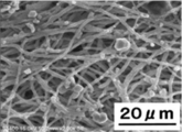
- FIG. 1 is a view showing an electron micrograph obtained in Example 3 before using the actual machine.
- FIG. 2 is an electron micrograph obtained after using the actual machine (surface) obtained in Example 3.
- FIG. 3 is a view showing an electron micrograph of the actual machine obtained in Example 3 after use (back side).
- the air filter for a CVD apparatus has, as an essential component, a polytetrafluoroethylene fiber (a) (PTFE) having an average fiber diameter of 10 nm to 50 ⁇ m.
- PTFE polytetrafluoroethylene fiber
- a filter medium layer (a) comprising fibers (a)), and a support layer (b) is laminated on one side or both sides of the filter medium layer (a) as necessary, as will be described later. Also good.
- the air filter of the present invention is in a state where the source gas and / or the exhaust gas can be filtered into a CVD (chemical vapor deposition) apparatus (specifically, the source gas supply port and / or the exhaust gas discharge port of the apparatus). And collect the particles (dust, dust) contained in the raw material gas and / or exhaust gas by filtering the raw material gas supplied into the device and / or the exhaust gas exhausted from inside the device ( Used to capture).
- the air filter of the present invention exhibits excellent air filter performance such as high heat resistance and high radical resistance (plasma resistance) as well as well-balanced air filter performance such as low pressure loss and high particle capture rate.
- CVD apparatus can be used for various types of CVD apparatuses regardless of the type of deposition and the mechanism of vapor deposition on the substrate.
- the CVD apparatus include a thermal CVD apparatus, a plasma CVD apparatus, a photo CVD apparatus, and a MOCVD (metalorgano-CVD) apparatus.
- the average fiber diameter of the PTFE fiber (a) is 10 nm to 50 ⁇ m, preferably 100 nm to 5000 nm.
- the pressure loss can be reduced and the air trapping performance can be improved, for example, the particle capture rate can be improved.
- the average fiber diameter of the PTFE fiber (a) is a region that is randomly observed by a scanning electron microscope (SEM) for the PTFE fiber (a) to be measured, and this region is then observed by SEM. (Magnification: 10,000 times) 10 PTFE fibers (a) were selected at random, the fiber diameters of the 10 selected PTFE fibers (a) were measured, and the obtained 10 fiber diameter values. Is an arithmetic average value calculated based on SEM.
- the PTFE fiber (a) when the PTFE fiber (a) is obtained by an electrospinning method, the PTFE concentration in the spinning solution, the atmospheric humidity during production, the tip diameter of the spinning nozzle, the applied voltage, the voltage density, etc. are appropriately adjusted. By doing so, PTFE fiber (a) having a desired average fiber diameter can be obtained.
- the electrospinning method the PTFE fiber (a) is obtained by using a spinning solution having a low PTFE concentration, lowering the atmospheric humidity, reducing the tip diameter of the spinning nozzle, increasing the applied voltage, or increasing the voltage density. The average fiber diameter tends to be small.
- PTFE fiber (a) is a fiber containing PTFE in a content of usually 95 to 100% by weight, preferably 99 to 100% by weight, more preferably 100% by weight.
- the air filter for a CVD apparatus according to the present invention can exhibit plasma resistance (radical resistance), heat resistance (particularly low heat shrinkage), and the like due to the characteristics of the PTFE fiber (a).
- the method for producing PTFE fiber (a) is not particularly limited as long as it is a method for producing PTFE fiber having an average fiber diameter in the above range, but is obtained by electrospinning (electrostatic spinning) method. Is preferred.
- the electrospinning method can easily obtain the PTFE fiber (a) having an average fiber diameter in the above range, and when the PTFE fiber (a) obtained by such a method is used for the air filter in the present invention, An air filter having a high particle trapping rate, low pressure loss, and high durability against heat, radicals and harmful substances can be realized.
- electrospinning method for example, from the spinning solution containing the above-mentioned PTFE and a solvent, and optionally additives (fiber forming agent, ionic surfactant, viscosity modifier, etc.), for example, US 2010/0193999 A1.
- a known electrospinning method such as the method described in Japanese Patent Publication No. 1993-2011 can be used.
- the porosity (porosity) of the filter medium layer (a) is preferably 0.60 to 0.95 from the viewpoint of securing a fluid flow path for preventing an increase in pressure loss and securing the filter medium strength. More preferably, it is 0.70 to 0.90.
- the basis weight of the filter medium layer (a) depends on the fiber diameter of the PTFE fiber, it is preferably 1 to 200 g / m 2 from the viewpoint of achieving both high particle capturing performance and low pressure loss and ensuring the filter medium strength. More preferably, it is 10 to 100 g / m 2 .
- the thickness of the filter medium layer (a) depends on the fiber diameter of the PTFE fiber, it is preferably 5 ⁇ m to 200 ⁇ m from the viewpoint of achieving both high particle capturing performance and low pressure loss.
- the porosity, basis weight, and thickness in the filter medium layer (a) are increased by increasing the spinning time or increasing the number of spinning nozzles when preparing the PTFE fiber (a) using the electrospinning method. Tend to.
- the manufacturing method of the air filter for CVD apparatus which concerns on this invention is not specifically limited,
- the process of manufacturing PTFE fiber (a) by the above-mentioned electrospinning method, and said PTFE fiber (a) in a sheet form It includes a step of accumulating to form an air filter.
- the filter medium layer (a) may be formed by collecting the PTFE fibers (a) in a sheet shape and forming them). Good).
- the air filter according to the present invention may be a filter medium layer (a) that is not laminated with a support layer (b) or the like (single-layer air filter), and may further include a filter medium layer.
- the support layer (b) or the like laminated air filter
- the laminated air filter includes, for example, a step of producing PTFE fibers (a) having a specific average fiber diameter as described above, and PTFE fibers (a) on at least one surface of the support layer (b). It can produce by implementing the process of accumulating in a sheet form and forming a filter medium layer (a). These two steps may be performed separately or simultaneously (that is, PTFE fibers (a) are accumulated in a sheet form on at least one surface of the support layer (b) while being produced).
- the filter medium layer (a) may be formed).
- a support body layer (b) the conventionally well-known support body layer in an air filter can be used, for example, the mesh comprised from iron, copper, stainless steel etc., for example, glass fiber, a cellulose fiber, polyolefin fiber, nylon Nonwoven fabrics composed of fibers, polyester fibers and the like can be mentioned.
- a support body layer (b) consists of a nonwoven fabric comprised from the mesh or glass fiber comprised from iron, copper, stainless steel, etc.
- the air filter of the present invention has at least one filter medium layer (c) made of a material different from the filter medium layer (a) in addition to the filter medium layer (a) comprising PTFE fibers (a). It may be.
- the air filter of the present invention may be composed of a filter medium layer (a) and one or more filter medium layers (c), and further laminated with one or more support layers (b). It may be a thing. In order to prevent clogging of the filter medium layer, it is preferable to collect dust for each particle diameter by a plurality of filter medium layers from the viewpoint of maintaining long-term performance of the air filter.
- the filter medium layer (c) is preferably metallic from the viewpoint of durability, and is a powder filter medium made of a sintered metal powder, a mesh filter medium made of a sintered metal wire mesh, a wool and a nonwoven cloth made of metal fibers. Conventionally known materials such as filter media can be used.
- the air filter of the present invention may be subjected to conventionally known processing within a range not impairing its performance, for example, may be subjected to pleating.
- PTFE fiber (a) 1 consisting only of PTFE was produced by an existing electrospinning method. The properties of the produced PTFE fiber (a) 1 were measured or evaluated based on the following “measurement method / evaluation criteria”. The obtained results are shown in Table 1.
- PTFE fiber (a) 1 was deposited (superposed) to produce a filter medium layer (a) 1 (length 10 cm, width 10 cm).
- the characteristics of the produced filter medium layer (a) 1 were measured or evaluated based on the following “measurement method / evaluation criteria”. The obtained results are shown in Table 1.
- Thickness of the filter medium layer (a) 1 The thickness of the filter medium layer (a) 1 was measured by LITEMATAC VL-50 (manufactured by Mitutoyo Corporation).
- the basis weight (g / m 2 ) of the filter medium layer (a) 1 of the filter medium layer (a) 1 was measured according to JIS L 1906 (2000).
- the porosity filter medium layer (a) 1 was cut into a 4 cm square (4 cm long ⁇ 4 cm wide) to prepare a test piece 1, and the weight (g) of the test piece 1 was measured. Then, by using the thickness measured in "2. Filter layer (a) thickness of 1" to calculate the volume above the test piece 1 (cm 3), further, the calculated volume (cm 3 ) And the weight (g) of the test piece 1, the density (g / cm 3 ) was calculated. The porosity was calculated based on the following formula (I) using the calculated density (g / cm 3 ).
- Average flow diameter and average flow diameter pressure Based on ASTM E1294-89 half dry method, average flow diameter and average flow diameter pressure were measured using Galwick (15.9 dyn / cm) as the immersion liquid.
- PTFE fiber (a) 1 was produced in the same manner as in Example 1, and then PTFE fiber (a) 1 was deposited (superposed) to filter medium layer (a) 2 (length 10 cm, width 10 cm, thickness 20 ⁇ m, A porosity of 0.76) was produced. The thickness and the porosity of the filter medium layer (a) 2 were measured in the same manner as in Example 1. The filter medium layer (a) 2 was cut into a size of 40 mm (A) length and 40 mm (B) width to prepare a sample. The prepared sample was left to stand for 30 minutes in an electric furnace (constant temperature dryer DRA430DA (manufactured by Advantech Toyo Co., Ltd.)) maintained at 260 ° C.
- an electric furnace constant temperature dryer DRA430DA (manufactured by Advantech Toyo Co., Ltd.)
- Example 3 The PTFE fiber (a) 1 produced in Example 1 was deposited (superposed) to produce a filter medium layer (a) 3 (length 20 cm, width 20 cm, thickness 59.5 ⁇ m). The thickness of the filter medium layer (a) 3 was measured in the same manner as in Example 1.
- an air filter (a) is manufactured by sequentially laminating a filter medium layer (a) 3, a stainless steel mesh as the support layer (b), and steel wool as the filter medium layer (c).
- a filter medium layer (a) 3 a stainless steel mesh as the support layer (b), and steel wool as the filter medium layer (c).
- the filter medium layer (c) of the air filter (a) was installed inside the CVD apparatus so that the filter medium layer (c) functions as a pre-filter (that is, the filter medium layer (a) 3 is outside the CVD apparatus). Installed).
- the actual machine operation was performed for 30 days, and the exhaust gas was passed through the air filter (a) when exhaust gas was discharged from the inside of the CVD apparatus to the outside.
- the air filter (a) was exposed to radical substances such as SiH 3 and SiH 2 contained in the exhaust gas under a high temperature condition of 200 ° C. with the exhaust gas.
- the filter medium layer (a) 3 is taken out, and the front surface (exhaust gas inlet side (inside the CVD apparatus)) and back surface (exhaust gas outlet surface (outside of the CVD apparatus)) of the filter medium layer (a) 3 are removed. Then, it was subjected to SEM observation (apparatus: S-3400N (manufactured by Hitachi High-Technologies Corporation), magnification: 2000 times) to obtain an electron micrograph.
- the filter medium layer (a) 3 before being incorporated into the CVD apparatus was subjected to SEM observation under the same conditions to obtain an electron micrograph. The obtained electron micrographs are shown in FIGS.
- the average flow diameter ( ⁇ m) and the average flow diameter were the same as in Example 1 except that the filter medium layer (a) 3 taken out after the actual machine operation was used instead of the filter medium layer (a) 1. Pressure (psi) was measured. The results are shown in Table 5.
- FIGS. 1 to 3 SEM photograph before operation of the actual machine (“before use of actual machine”) (FIG. 1), SEM photograph after operation of the actual machine (“after use of actual machine (surface)” (FIG. 2) and “actual machine” Comparing “after use (back surface)” (FIG. 3)), it can be seen that the shape of the PTFE fiber (a) 1 constituting the filter medium layer (a) 3 is not changed at all.
- the filter medium layer (a) 3 has a function of capturing particles in the exhaust gas discharged from the inside of the CVD apparatus to the outside.
- the filter medium layer (a) 3 has durability such as radical resistance and heat resistance required for an air filter for a CVD apparatus.
Landscapes
- Chemical & Material Sciences (AREA)
- Chemical Kinetics & Catalysis (AREA)
- General Chemical & Material Sciences (AREA)
- Engineering & Computer Science (AREA)
- Materials Engineering (AREA)
- Mechanical Engineering (AREA)
- Metallurgy (AREA)
- Organic Chemistry (AREA)
- Filtering Materials (AREA)
- Chemical Vapour Deposition (AREA)
Applications Claiming Priority (2)
| Application Number | Priority Date | Filing Date | Title |
|---|---|---|---|
| JP2012-062364 | 2012-03-19 | ||
| JP2012062364A JP2013193025A (ja) | 2012-03-19 | 2012-03-19 | Cvd装置用エアフィルターおよびそれを有するcvd装置 |
Publications (1)
| Publication Number | Publication Date |
|---|---|
| WO2013141070A1 true WO2013141070A1 (fr) | 2013-09-26 |
Family
ID=49222530
Family Applications (1)
| Application Number | Title | Priority Date | Filing Date |
|---|---|---|---|
| PCT/JP2013/056731 Ceased WO2013141070A1 (fr) | 2012-03-19 | 2013-03-12 | Filtre à air pour appareil de dépôt chimique en phase vapeur et appareil de dépôt chimique en phase vapeur équipé de celui-ci |
Country Status (3)
| Country | Link |
|---|---|
| JP (1) | JP2013193025A (fr) |
| TW (1) | TW201347826A (fr) |
| WO (1) | WO2013141070A1 (fr) |
Families Citing this family (2)
| Publication number | Priority date | Publication date | Assignee | Title |
|---|---|---|---|---|
| JP6155490B2 (ja) * | 2013-12-20 | 2017-07-05 | 日本アイ・ティ・エフ株式会社 | 成膜装置 |
| JP2016022415A (ja) * | 2014-07-18 | 2016-02-08 | 日本バルカー工業株式会社 | ポリテトラフルオロエチレンファイバを含む不織布層からなる防水通気膜と接着層とを有する防水通気部材およびその用途 |
Citations (1)
| Publication number | Priority date | Publication date | Assignee | Title |
|---|---|---|---|---|
| JP2001170461A (ja) * | 1999-10-07 | 2001-06-26 | Daikin Ind Ltd | エアフィルター濾材、それを用いたエアフィルターパックおよびエアフィルターユニット並びにエアフィルター濾材の製造方法 |
-
2012
- 2012-03-19 JP JP2012062364A patent/JP2013193025A/ja active Pending
-
2013
- 2013-03-12 WO PCT/JP2013/056731 patent/WO2013141070A1/fr not_active Ceased
- 2013-03-15 TW TW102109176A patent/TW201347826A/zh unknown
Patent Citations (1)
| Publication number | Priority date | Publication date | Assignee | Title |
|---|---|---|---|---|
| JP2001170461A (ja) * | 1999-10-07 | 2001-06-26 | Daikin Ind Ltd | エアフィルター濾材、それを用いたエアフィルターパックおよびエアフィルターユニット並びにエアフィルター濾材の製造方法 |
Also Published As
| Publication number | Publication date |
|---|---|
| TW201347826A (zh) | 2013-12-01 |
| JP2013193025A (ja) | 2013-09-30 |
Similar Documents
| Publication | Publication Date | Title |
|---|---|---|
| JP5012990B2 (ja) | 多孔膜を備える濾材、その製造方法、フィルタパック、ならびにフィルタユニット | |
| EP1878482B1 (fr) | Milieu filtrant, procede de production, procede d' utilisation et ensemble de filtration | |
| Bao et al. | Verification of slip flow in nanofiber filter media through pressure drop measurement at low-pressure conditions | |
| CN101580598B (zh) | 聚四氟乙烯多孔膜、其制造方法及过滤材料 | |
| KR101353726B1 (ko) | 폴리테트라플루오로에틸렌 다공질막의 제조 방법과 필터 여과재 및 필터 유닛 | |
| TWI503163B (zh) | Teflon porous film and air filter filter | |
| JP5037034B2 (ja) | フィルタ濾材とその製造方法および使用方法ならびにフィルタユニット | |
| CN108136343B (zh) | 空气过滤器滤材、空气过滤器组件以及空气过滤器单元 | |
| JP2000300921A (ja) | エアフィルタ濾材およびそれを用いたエアフィルタユニット | |
| Shao et al. | Using modified raw materials to fabricate electrospun, superhydrophobic poly (lactic acid) multiscale nanofibrous membranes for air-filtration applications | |
| Xu et al. | Preparation and properties of PTFE hollow fiber membranes for the removal of ultrafine particles in PM 2.5 with repetitive usage capability | |
| JP2014124578A (ja) | フィルター用ろ材およびその製造方法 | |
| KR20200052687A (ko) | 초발수, 초발유 기능이 부여된 여과체 및 이의 제조장치 | |
| KR101308358B1 (ko) | 비대칭 다공성 시트, 그 제조방법 및 그를 이용한 공조용 에어필터 | |
| JP2002370020A (ja) | タービン用吸気フィルタ濾材およびその使用方法と製造方法 | |
| JP2014069115A (ja) | フィルター用ろ材およびその製造方法 | |
| CN105899285A (zh) | 聚四氟乙烯多孔膜的制造方法、防水透气构件的制造方法和空气过滤器过滤介质的制造方法 | |
| WO2013141070A1 (fr) | Filtre à air pour appareil de dépôt chimique en phase vapeur et appareil de dépôt chimique en phase vapeur équipé de celui-ci | |
| EP3804832A1 (fr) | Milieu filtrant et unité filtrante comprenant celui-ci | |
| CN104582810B (zh) | 细纤维过滤介质和方法 | |
| JP2005169167A (ja) | エアフィルタ濾材 | |
| JP2002346319A (ja) | タービン用吸気フィルタ濾材 | |
| CN116806164A (zh) | 空气过滤器滤材、空气过滤器滤材的制造方法、口罩用滤材及褶裥状口罩用滤材 | |
| JP6957472B2 (ja) | 不織布 | |
| JP2002370009A (ja) | タービン用吸気フィルタ濾材およびその使用方法 |
Legal Events
| Date | Code | Title | Description |
|---|---|---|---|
| 121 | Ep: the epo has been informed by wipo that ep was designated in this application |
Ref document number: 13764187 Country of ref document: EP Kind code of ref document: A1 |
|
| NENP | Non-entry into the national phase |
Ref country code: DE |
|
| 122 | Ep: pct application non-entry in european phase |
Ref document number: 13764187 Country of ref document: EP Kind code of ref document: A1 |