WO2013141380A1 - タービンハウジングアセンブリ - Google Patents
タービンハウジングアセンブリ Download PDFInfo
- Publication number
- WO2013141380A1 WO2013141380A1 PCT/JP2013/058396 JP2013058396W WO2013141380A1 WO 2013141380 A1 WO2013141380 A1 WO 2013141380A1 JP 2013058396 W JP2013058396 W JP 2013058396W WO 2013141380 A1 WO2013141380 A1 WO 2013141380A1
- Authority
- WO
- WIPO (PCT)
- Prior art keywords
- scroll
- turbine housing
- exhaust gas
- exhaust
- turbine
- Prior art date
- Legal status (The legal status is an assumption and is not a legal conclusion. Google has not performed a legal analysis and makes no representation as to the accuracy of the status listed.)
- Ceased
Links
Images





Classifications
-
- F—MECHANICAL ENGINEERING; LIGHTING; HEATING; WEAPONS; BLASTING
- F01—MACHINES OR ENGINES IN GENERAL; ENGINE PLANTS IN GENERAL; STEAM ENGINES
- F01D—NON-POSITIVE DISPLACEMENT MACHINES OR ENGINES, e.g. STEAM TURBINES
- F01D25/00—Component parts, details, or accessories, not provided for in, or of interest apart from, other groups
- F01D25/24—Casings; Casing parts, e.g. diaphragms, casing fastenings
-
- F—MECHANICAL ENGINEERING; LIGHTING; HEATING; WEAPONS; BLASTING
- F01—MACHINES OR ENGINES IN GENERAL; ENGINE PLANTS IN GENERAL; STEAM ENGINES
- F01D—NON-POSITIVE DISPLACEMENT MACHINES OR ENGINES, e.g. STEAM TURBINES
- F01D17/00—Regulating or controlling by varying flow
- F01D17/10—Final actuators
- F01D17/12—Final actuators arranged in stator parts
- F01D17/14—Final actuators arranged in stator parts varying effective cross-sectional area of nozzles or guide conduits
-
- F—MECHANICAL ENGINEERING; LIGHTING; HEATING; WEAPONS; BLASTING
- F01—MACHINES OR ENGINES IN GENERAL; ENGINE PLANTS IN GENERAL; STEAM ENGINES
- F01D—NON-POSITIVE DISPLACEMENT MACHINES OR ENGINES, e.g. STEAM TURBINES
- F01D9/00—Stators
- F01D9/02—Nozzles; Nozzle boxes; Stator blades; Guide conduits, e.g. individual nozzles
- F01D9/026—Scrolls for radial machines or engines
-
- F—MECHANICAL ENGINEERING; LIGHTING; HEATING; WEAPONS; BLASTING
- F05—INDEXING SCHEMES RELATING TO ENGINES OR PUMPS IN VARIOUS SUBCLASSES OF CLASSES F01-F04
- F05D—INDEXING SCHEME FOR ASPECTS RELATING TO NON-POSITIVE-DISPLACEMENT MACHINES OR ENGINES, GAS-TURBINES OR JET-PROPULSION PLANTS
- F05D2220/00—Application
- F05D2220/40—Application in turbochargers
-
- F—MECHANICAL ENGINEERING; LIGHTING; HEATING; WEAPONS; BLASTING
- F05—INDEXING SCHEMES RELATING TO ENGINES OR PUMPS IN VARIOUS SUBCLASSES OF CLASSES F01-F04
- F05D—INDEXING SCHEME FOR ASPECTS RELATING TO NON-POSITIVE-DISPLACEMENT MACHINES OR ENGINES, GAS-TURBINES OR JET-PROPULSION PLANTS
- F05D2230/00—Manufacture
- F05D2230/20—Manufacture essentially without removing material
- F05D2230/23—Manufacture essentially without removing material by permanently joining parts together
- F05D2230/232—Manufacture essentially without removing material by permanently joining parts together by welding
-
- F—MECHANICAL ENGINEERING; LIGHTING; HEATING; WEAPONS; BLASTING
- F05—INDEXING SCHEMES RELATING TO ENGINES OR PUMPS IN VARIOUS SUBCLASSES OF CLASSES F01-F04
- F05D—INDEXING SCHEME FOR ASPECTS RELATING TO NON-POSITIVE-DISPLACEMENT MACHINES OR ENGINES, GAS-TURBINES OR JET-PROPULSION PLANTS
- F05D2250/00—Geometry
- F05D2250/50—Inlet or outlet
- F05D2250/51—Inlet
Definitions
- the present invention relates to a turbine housing assembly in which a plurality of components are combined to constitute a turbine housing into which a turbine wheel rotated by exhaust gas introduced from an engine is inserted.
- turbochargers are known to improve the output by In recent years, when this turbocharger is used for vehicles, weight reduction, cost reduction, ease of manufacture, reduction of heat capacity, etc. are required, and instead of the conventional cast turbine housing, it is made of sheet metal. Turbine housings are to be used.
- Patent Document 1 discloses a spiral exhaust gas flow path formed by abutting two left and right plate-like or bowl-like sheet metal members and welding in a circumferential direction.
- a turbine housing with a scroll is disclosed.
- Patent Document 2 includes a scroll-shaped housing manufactured from a sheet metal member and having a spiral exhaust gas flow channel formed therein, and an outer shell manufactured from the sheet metal member, and the outer shell has a scroll shape.
- a turbine housing is disclosed that is configured to enclose the housing.
- a scroll portion is prepared by preparing a sheet metal member having a complicated shape processed into a plate shape or a bowl shape on the left and right two sheets and abutting the two in a circumferential direction. And it takes time and effort to manufacture the scroll portion. Further, although the sheet metal scroll portion is directly connected to the cast bearing housing (FIG. 3), the details of the connection portion are not disclosed.
- the turbine housing of patent document 2 mentioned above is comprised by fitting a housing, a bearing ring, etc., and there existed a problem in the sealability of the waste gas in a housing.
- the turbine housing of Patent Document 3 it is necessary to provide an outer shell so as to surround the scroll-like housing, and there has been a problem that sufficient weight reduction and heat capacity reduction of the turbine housing can not be achieved.
- the present invention has been made in view of the problems of the prior art as described above, and it is possible to further reduce the weight, facilitate the manufacture, reduce the cost, and reduce the heat capacity as compared with the conventional sheet metal turbine housing. It is an object of the present invention to provide a turbine housing assembly and a method of manufacturing the same.
- the present invention is an invention made to achieve the above-mentioned object,
- the turbine housing assembly of the present invention In a turbine housing assembly configured by combining a plurality of components, a turbine housing into which a turbine wheel rotated by exhaust gas introduced from an engine is inserted, It is formed in a bottomed cylindrical shape having a peripheral wall portion and a bottom portion, and a spiral exhaust gas flow path is formed in the bottomed cylindrical shape through which the exhaust gas flowing from the exhaust gas inlet flows.
- the scroll portion is formed by processing a single sheet metal, and on the back surface side of the bottom surface portion of the scroll portion, a recessed portion through which the exhaust gas outlet passes and a bottom surface of the exhaust gas flow path convexly provided on the back surface Forming a convex portion, and the convex portion is formed to surround the concave portion, By connecting the recessed portion of the scroll portion and one end portion of the exhaust portion in the axial direction of the turbine, a gap is formed between the outer peripheral surface of the exhaust portion and the convex portion of the scroll portion.
- the exhaust unit and the exhaust gas outlet of the scroll unit are in communication with each other.
- the element is disassembled into a scroll portion in which a spiral exhaust gas flow path is formed inside the turbine housing and a tubular exhaust portion, and the scroll portion is made of one sheet metal. It is formed by processing. Further, by connecting the recessed portion of the scroll portion and one end portion of the exhaust portion in the axial direction of the turbine, a clearance is formed between the outer peripheral surface of the exhaust portion and the convex portion of the scroll portion. And the exhaust gas outlet of the scroll portion are communicated.
- the turbine housing is elementally disassembled into the scroll portion and the exhaust portion, and the scroll portion is formed by processing one sheet metal, the heat capacity of the turbine housing can be reduced and the weight reduction of the turbine housing is achieved. Can be In addition, since the sheet metal is processed and formed, manufacture of the scroll portion is easy.
- the turbine housing is element-disassembled into the scroll portion and the exhaust portion, and a gap is formed between the outer peripheral surface of the exhaust portion and the convex portion of the scroll portion.
- the exhaust portion can be formed of a material having a lower heat resistance than the scroll portion, that is, an inexpensive material having a lower nickel content than the scroll portion, and cost reduction of the turbine housing can be achieved.
- a rib be formed between the outer peripheral surface of the exhaust portion and the convex portion of the scroll portion. If such a rib is formed between the outer peripheral surface of the exhaust portion and the convex portion of the scroll portion, the scroll portion and the exhaust portion are more strongly connected.
- the connecting portion is connected to a bearing housing in which a bearing for supporting the rotation shaft of the turbine wheel is accommodated, and the connecting portion is formed by processing one sheet metal and the scroll portion
- the scroll portion and the connection portion are separately welded to an annular lid portion orthogonal to the axial direction of the turbine, and connected in the axial direction of the turbine through the annular lid portion.
- the turbine housing is divided into the scroll portion, the exhaust portion, and the connection portion, and the connection portion is configured separately from the scroll portion, thereby forming each component constituting the turbine housing assembly of the present invention.
- the shape can be simple, and the manufacture of each component can be facilitated.
- the connecting portion, the annular lid portion, and the scroll constituting the turbine housing assembly of the present invention The components of the part and the exhaust part are all coupled in the axial direction of the turbine, which improves the assemblability of the turbine housing assembly.
- the turbine housing assembly of the present invention is standardized because the element is disassembled into a scroll portion in which a spiral exhaust gas flow path is formed inside the turbine housing, a tubular exhaust portion, and a connection portion coupled with the bearing housing. It can be configured as an assembly of a plurality of integrated components (modules) and can be easily manufactured.
- the sheet metal is processed and formed also for the connecting portion as well as the scroll portion, the heat capacity of the turbine housing can be reduced, and the weight reduction of the turbine housing can be achieved. Moreover, since it processes and forms one sheet metal, manufacture of a connection part is also easy.
- the turbine housing is disassembled into the scroll portion, the exhaust portion and the connection portion and the scroll portion and the connection portion are connected by welding, the sealability is excellent and the conventional outer shell is unnecessary. For this reason, weight reduction and heat capacity reduction of a turbine housing can be achieved.
- the turbine housing is disassembled into the scroll portion, the exhaust portion, and the connection portion, and the scroll portion and the connection portion are connected in the turbine axial direction via the annular lid portion orthogonal to the turbine axial direction, The effect of the hot exhaust gases can be shielded by the annular lid.
- the turbine housing assembly of the present invention thus configured includes a variable nozzle mechanism that regulates the flow of exhaust gas to the turbine wheel, and the variable nozzle mechanism is inserted into the scroll portion and the connection portion. . That is, the turbine housing of the variable displacement turbocharger is configured.
- a turbine housing assembly that achieves further weight reduction, easier manufacturing, lower cost, and lower heat capacity as compared with a conventional sheet metal turbine housing and a method of manufacturing the turbine housing assembly Can be provided.
- FIG. 1 is a perspective view of a turbine housing assembly of the present invention.
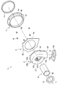
- 1 is an exploded perspective view of a turbine housing assembly of the present invention.
- FIG. 1 is a front view of a turbine housing assembly of the present invention.
- FIG. 1 is a side view of a turbine housing assembly of the present invention.
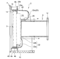
- FIG. 4 is a cross-sectional view taken along the line AA in FIG.
- FIG. 4 is a cross-sectional view taken along the line BB in FIG.
- FIG. 4 is a cross-sectional view taken along the line CC in FIG. 3
- FIG. 5 is a cross-sectional view taken along the line DD in FIG.
- FIG. 5 is a cross-sectional view taken along line EE in FIG. 4;
- FIG. 7 is a cross-sectional view of a turbine housing assembly according to another embodiment of the present invention. It is an enlarged view of a part in FIG.
- FIG. 1 is a perspective view showing a turbine housing assembly of the present invention
- FIG. 2 is an exploded perspective view of the turbine housing assembly of the present invention
- 3 is a front view of the turbine housing assembly of the present invention
- FIG. 4 is a side view of the turbine housing assembly of the present invention
- FIGS. 5 to 9 are cross sections taken along line A-A to E of FIG. FIG.
- the turbine housing assembly 1 of the present invention is not particularly limited, but is, for example, a turbine housing of a VG (Variable Geometry) turbocharger provided with a variable nozzle mechanism.
- the VG turbocharger has a variable nozzle mechanism in a turbine housing, and adjusts the nozzle opening degree of the variable nozzle mechanism according to the engine conditions to control the flow rate of the exhaust gas to be introduced. Then, the boost pressure is controlled to an optimal pressure by increasing or decreasing the rotational speed of the turbine wheel according to the exhaust gas flow rate.
- the turbine housing assembly 1 of the present invention is shown in FIG. 1 by assembling a plurality of components such as the scroll portion 2, the connection portion 4, the annular lid 6 and the exhaust portion 8. It is configured as And as shown in FIG. 1, the variable nozzle mechanism 3 and the turbine wheel 5 are inserted into the assembled turbine housing assembly 1 from the front side. And, on the front side of the assembled turbine housing assembly 1, a bearing housing (not shown) that accommodates a bearing that rotatably supports the rotational shaft of the turbine wheel 5 is coupled.
- the scroll part 2 is formed in the bottomed cylindrical shape which has the surrounding wall part 20 and the bottom face part 22 as shown in FIG.1, FIG.2, FIG.6 etc. FIG. Then, as shown in FIG. 8, inside the bottomed cylindrical scroll portion 2, the exhaust gas flow path 2 A is formed in a spiral shape along the peripheral wall portion 20, and the bottom portion 22 is formed in the spiral shape.
- the exhaust gas outlet 2B penetrates to a position surrounded by the formed exhaust gas flow path 2A.
- the bottom surface 22a of the swirling exhaust gas flow channel 2A is formed to be convex on the back side of the bottom surface portion 22. Further, the cross section of the flow passage is formed so as to be uniformly shallow toward a predetermined circumferential direction. Thereby, the back surface side of the bottom surface portion 22 is formed in an uneven shape, and a recessed portion 22b through which the exhaust gas outlet 2B penetrates and a convex portion 22a formed in a protruding shape surrounding the recessed portion 22b are formed. .
- a flange portion 20a protruding outward in a direction substantially perpendicular to the peripheral wall portion 20 is formed. Further, in the flange portion 20a, a plurality of receiving portions 20b protruding outward from the flange portion 20a are formed at equal intervals in the circumferential direction.
- the exhaust gas outlet 24 is formed at the upstream end of the exhaust gas flow path 2A.
- a flat engine-side flange 10 is connected to the exhaust gas inlet 24 by, for example, welding.
- a bolt insertion hole 10b is formed in the engine side flange portion 10, and is fastened by an exhaust pipe (not shown) and a bolt.
- the connecting portion 4 is a flat flange portion 4a formed in an annular shape, and an annular projecting portion protruding perpendicularly to the flange portion 4a. And 4b.
- the flange portion 4a is provided with a plurality of bush insertion holes 4c at equal intervals in the circumferential direction, and each of the plurality of bush insertion holes 4c has a cylindrical shape, and a groove is cut in the through hole
- the screw bush 16 is inserted.
- the screw bush 16 is used as a bolt hole when fastening the above-described bearing housing and the connecting portion 4 with a bolt or the like.
- the annular lid 6 is composed of a flat plate 6a formed in an annular shape and a receiving portion 6b extended outward from the flat plate 6a.
- the receiving portion 6 b is installed at the same distance as the receiving portion 20 b of the scroll portion 2 described above and the position corresponding to the bush insertion hole 4 c of the connecting portion 4.
- the scroll portion 2, the connection portion 4 and the annular lid portion 6 are formed by processing a single thin plate. That is, it is formed by plastically deforming a flat sheet metal into a predetermined shape by a method such as bending or pressing, and partially cutting out an unnecessary portion by punching or the like. Moreover, heat-resistant steels, such as austenitic stainless steel, are used suitably for the material of these scroll part 2, the connection part 4, and the cyclic
- the exhaust part 8 is formed in a tubular shape as shown in FIG. Then, one end 8a of the exhaust unit 8 is joined, for example, by welding to the recess 22b on the back side of the bottom surface 22 of the scroll unit 2 described above, and is communicated with the exhaust gas outlet 2B. Further, a muffler side flange portion 12 formed of an annular flat plate member is coupled to the other end 8 b of the exhaust portion 8 by, for example, welding or the like. Then, by connecting the muffler side flange portion 12 and the muffler side exhaust pipe (not shown), the exhaust gas flowing through the exhaust portion 8 is exhausted from the muffler through the muffler side exhaust pipe to the outside of the vehicle ing.
- a gap a is formed between the outer peripheral surface of the exhaust portion 8 coupled to the recessed portion 22b of the scroll portion 2 and the convex portion 22a.
- the exhaust portion 8 is coupled to the scroll portion 2 so that the gap a is formed between the outer peripheral surface of the exhaust portion 8 and the convex portion 22 a of the scroll portion 2, the exhaust gas flow path 2A is The influence of the flowing high temperature exhaust gas is less likely to be transmitted to the exhaust unit 8.
- the gap a between the outer circumferential surface of the exhaust portion 8 and the convex portion 22 a means the distance between the two in the direction perpendicular to the outer surface of the exhaust portion 8.
- the temperature of the exhaust gas flowing into the exhaust unit 8 is about 100 degrees lower than the temperature of the exhaust gas flowing through the exhaust gas passage 2A. Therefore, if exhaust part 8 and scroll part 2 are combined so that gap a is formed between the outer surface of exhaust part 8 and convex part 22a, high temperature exhaust gas flowing through exhaust gas flow path 2A Since the influence of the above becomes difficult to be transmitted to the exhaust part 8, the material of the exhaust part 8 can be selected for the temperature of the exhaust gas passing through the exhaust part 8. Therefore, it is possible to form the material of the exhaust unit 8 from a material having heat resistance lower than that of the scroll unit 2 (specifically, an inexpensive stainless material having a low nickel content).
- a reinforcing rib 25 is provided on the inner peripheral side of the convex portion 22 a of the scroll portion 2. Then, the reinforcing rib 25 and the outer peripheral surface of the exhaust portion 8 are joined, for example, by welding. Further, as shown in FIG. 9, a plurality of (for example, three) reinforcing ribs 25 are provided at equal intervals in the circumferential direction. By providing such a reinforcing rib 25, the scroll portion 2 and the exhaust portion 8 are more strongly connected.
- the reinforcing rib 25 of this embodiment is integrally provided with the convex part 22a of the scroll part 2 as shown in FIG. 5, this invention is not limited to this.
- the reinforcing rib 25 may be provided integrally with the exhaust portion 8 so that the reinforcing rib 25 and the inner peripheral side of the convex portion 22a are coupled.
- the reinforcing rib 25 is provided separately from the scroll portion 2 and the exhaust portion 8, and the reinforcing rib 25 is coupled to the inner peripheral side of the convex portion 22a and the outer peripheral surface of the exhaust portion 8 It may be done.
- an annular ring member 14 is fitted on the front side of the connecting portion 4.
- the ring member 14 is inserted to a position where the ring member 14 abuts on the annular lid 6 as shown in FIGS.
- the variable nozzle mechanism 3 is inserted into the inner circumferential side of the ring member 14. If such a ring member 14 is inserted into the connecting portion 4, it is possible to easily position the variable nozzle mechanism 3.
- the element is disassembled into the scroll portion 2 and the tubular exhaust portion 8 in which the spiral exhaust gas flow path is formed inside the turbine housing. It is formed by processing a sheet metal. Further, by connecting the recessed portion 20b of the scroll portion 2 and the one end 8a of the exhaust portion 8 in the turbine axial direction, a gap a is formed between the outer peripheral surface of the exhaust portion 8 and the convex portion 20a of the scroll portion 2. In the formed state, the exhaust unit 8 and the exhaust gas outlet 2B of the scroll unit 2 are in communication with each other.
- the turbine housing is elementally disassembled into the scroll portion 2 and the exhaust portion 8 and the scroll portion 2 is formed by processing one sheet metal, the heat capacity of the turbine housing can be reduced, and Weight reduction can be achieved.
- the sheet metal is processed and formed, manufacture of the scroll portion 2 is easy.
- the turbine housing is element-disassembled into the scroll portion 2 and the exhaust portion 8, and the clearance a is formed between the outer peripheral surface of the exhaust portion 8 and the convex portion 20 a of the scroll portion 2
- the exhaust portion 8 can be formed of a material having a heat resistance lower than that of the scroll portion 2, specifically, an inexpensive stainless material having a lower nickel content than the scroll portion 2, thereby achieving cost reduction of the turbine housing it can.
- the connection between the scroll portion 2 and the exhaust portion 8 is further strengthened. be able to.
- the connecting portion 4 is formed by processing one sheet metal, and is configured separately from the scroll portion 2, and the scroll portion 2 and the connecting portion 4 Are connected in the axial direction of the turbine via an annular lid 6 orthogonal to the axial direction of the turbine.
- the turbine housing is divided into the scroll portion 2, the exhaust portion 8 and the connecting portion 4, and the connecting portion 4 is configured separately from the scroll portion 2 to configure the turbine housing assembly 1 of the present invention.
- Each component can be formed into a simple shape, and the manufacture of each component can be facilitated.
- the scroll portion 2 and the connecting portion 4 are connected in the turbine axial direction via the annular lid portion 6 orthogonal to the turbine axial direction line 7, the connecting portion 4, the annular lid portion 6, the scroll portion 2
- the respective components of the exhaust portion 8 are all coupled in the axial direction of the turbine, and the assemblability of the turbine housing assembly 1 is improved.
- the turbine housing assembly 1 of the present invention can be configured as an assembly of standardized components (modules), and the manufacture of the turbine housing can be facilitated.
- connection part 4 is also easy.
- the sealing performance is excellent.
- Such an external shell is unnecessary. For this reason, weight reduction and heat capacity reduction of a turbine housing can be achieved.
- the turbine housing is disassembled into the scroll portion, the exhaust portion 8 and the connecting portion 4 and the turbine 2 is separated by the annular lid portion 6 orthogonal to the axial line 7 of the scroll portion 2 and the connecting portion 4. Because of the axial connection, the influence of the high temperature exhaust gas in the scroll portion 2 can be shielded by the annular lid 6. Therefore, the connecting portion 4 can be formed of a stainless steel material having a lower heat resistance than the scroll portion 2, that is, an inexpensive stainless steel material having a lower nickel content than the scroll portion 2. Thereby, cost reduction of a turbine housing can be attained compared with a case where the whole turbine housing is formed with the same material.
- each component such as the scroll portion 2, the connecting portion 4, and the annular lid portion 6 has a simple shape And the manufacture of each component can be facilitated. At this time, forming the annular lid 6 also by processing one sheet metal contributes to weight reduction and heat capacity reduction of the turbine housing.
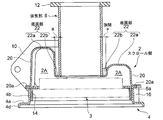
- FIG. 10 is a cross-sectional view of a turbine housing assembly according to another embodiment of the present invention.
- the scroll portion 2 of the present invention is configured such that one end portion 8a of the exhaust portion 8 is formed so that the periphery of the exhaust gas outlet 2B is bent back on the bottom portion 22 thereof.
- the inserted insertion part 22c may be formed. If such a fitting portion 22c is formed, one end 8a of the exhaust portion 8 is fitted in the fitting portion 22c, and the one end 8a and the inner peripheral side of the fitting portion 22c are shown in FIG. It can be joined by fillet weld 23 as shown. In this way, by inserting one end 8a of the exhaust part 8 into the insertion part 22c, the positioning of the exhaust part 8 and the temporary fixing at the time of welding can be performed simultaneously, so the welding workability is excellent. .
- the present invention can be suitably used as a turbine housing assembly for a turbocharger, preferably a turbine housing assembly for an on-vehicle VG turbocharger.
Landscapes
- Engineering & Computer Science (AREA)
- Mechanical Engineering (AREA)
- General Engineering & Computer Science (AREA)
- Supercharger (AREA)
Priority Applications (3)
| Application Number | Priority Date | Filing Date | Title |
|---|---|---|---|
| CN201380015195.0A CN104379898B (zh) | 2012-03-23 | 2013-03-22 | 涡轮壳体组件 |
| US14/386,425 US9708932B2 (en) | 2012-03-23 | 2013-03-22 | Turbine housing assembly |
| EP13764393.8A EP2829702B1 (de) | 2012-03-23 | 2013-03-22 | Turbinengehäuseanordnung |
Applications Claiming Priority (2)
| Application Number | Priority Date | Filing Date | Title |
|---|---|---|---|
| JP2012068210A JP5986767B2 (ja) | 2012-03-23 | 2012-03-23 | タービンハウジングアセンブリ |
| JP2012-068210 | 2012-03-23 |
Publications (1)
| Publication Number | Publication Date |
|---|---|
| WO2013141380A1 true WO2013141380A1 (ja) | 2013-09-26 |
Family
ID=49222828
Family Applications (1)
| Application Number | Title | Priority Date | Filing Date |
|---|---|---|---|
| PCT/JP2013/058396 Ceased WO2013141380A1 (ja) | 2012-03-23 | 2013-03-22 | タービンハウジングアセンブリ |
Country Status (5)
| Country | Link |
|---|---|
| US (1) | US9708932B2 (de) |
| EP (1) | EP2829702B1 (de) |
| JP (1) | JP5986767B2 (de) |
| CN (1) | CN104379898B (de) |
| WO (1) | WO2013141380A1 (de) |
Cited By (3)
| Publication number | Priority date | Publication date | Assignee | Title |
|---|---|---|---|---|
| WO2015097890A1 (ja) | 2013-12-27 | 2015-07-02 | 三菱重工業株式会社 | タービンハウジング |
| WO2017078088A1 (ja) * | 2015-11-06 | 2017-05-11 | カルソニックカンセイ株式会社 | タービンハウジング |
| JP2017089450A (ja) * | 2015-11-06 | 2017-05-25 | カルソニックカンセイ株式会社 | タービンハウジング |
Families Citing this family (10)
| Publication number | Priority date | Publication date | Assignee | Title |
|---|---|---|---|---|
| JP2015203398A (ja) * | 2014-04-16 | 2015-11-16 | カルソニックカンセイ株式会社 | ターボチャージャ |
| JP2015214967A (ja) * | 2014-04-22 | 2015-12-03 | カルソニックカンセイ株式会社 | ターボチャージャ |
| CN105370625A (zh) * | 2015-11-27 | 2016-03-02 | 无锡蠡湖增压技术股份有限公司 | 一种冷加工的压气机壳 |
| US10436069B2 (en) * | 2017-01-30 | 2019-10-08 | Garrett Transportation I Inc. | Sheet metal turbine housing with biaxial volute configuration |
| US10494955B2 (en) | 2017-01-30 | 2019-12-03 | Garrett Transportation I Inc. | Sheet metal turbine housing with containment dampers |
| US10472988B2 (en) | 2017-01-30 | 2019-11-12 | Garrett Transportation I Inc. | Sheet metal turbine housing and related turbocharger systems |
| US10544703B2 (en) | 2017-01-30 | 2020-01-28 | Garrett Transportation I Inc. | Sheet metal turbine housing with cast core |
| US10690144B2 (en) | 2017-06-27 | 2020-06-23 | Garrett Transportation I Inc. | Compressor housings and fabrication methods |
| US11136997B2 (en) * | 2019-07-23 | 2021-10-05 | Ford Global Technologies, Llc | Methods and systems for a compressor housing |
| US11732729B2 (en) | 2021-01-26 | 2023-08-22 | Garrett Transportation I Inc | Sheet metal turbine housing |
Citations (3)
| Publication number | Priority date | Publication date | Assignee | Title |
|---|---|---|---|---|
| JP2006527322A (ja) * | 2003-06-06 | 2006-11-30 | アイ・エイチ・アイ チャージング システムズ インターナショナル ゲーエムベーハー | 排ガスターボチャージャ用排ガスタービン |
| JP2007224827A (ja) * | 2006-02-23 | 2007-09-06 | Aisin Takaoka Ltd | タービンハウジング |
| JP2008057448A (ja) | 2006-08-31 | 2008-03-13 | Toyota Motor Corp | タービンハウジング |
Family Cites Families (11)
| Publication number | Priority date | Publication date | Assignee | Title |
|---|---|---|---|---|
| JPS61132800A (ja) | 1984-11-29 | 1986-06-20 | Mitsubishi Heavy Ind Ltd | 過給機用コンプレツサ−ハウジング及びその製造方法 |
| US4850797A (en) * | 1988-01-21 | 1989-07-25 | Benson Steven R | Double chambered turbine housing and seal |
| DE10061846B4 (de) * | 2000-12-12 | 2004-09-09 | Daimlerchrysler Ag | Abgasturbolader für eine Brennkraftmaschine |
| DE10218436C1 (de) | 2002-04-25 | 2003-08-14 | Benteler Automobiltechnik Gmbh | Abgasturbine für einen Turbolader |
| GB0223756D0 (en) * | 2002-10-14 | 2002-11-20 | Holset Engineering Co | Compressor |
| DE50312707D1 (de) * | 2003-03-19 | 2010-06-24 | Abb Turbo Systems Ag | Abgasturbinengehäuse |
| DE10352960B4 (de) * | 2003-11-13 | 2006-06-14 | Benteler Automobiltechnik Gmbh | Gehäuseanordnung für den Turbolader einer Brennkraftmaschine |
| DE102004039477B4 (de) | 2004-08-14 | 2015-01-08 | Ihi Charging Systems International Gmbh | Turbinengehäuse für einen Abgasturbolader |
| EP2351920B1 (de) | 2008-11-05 | 2016-04-13 | IHI Corporation | Turbolader |
| US8372335B2 (en) * | 2010-01-14 | 2013-02-12 | Honeywell International Inc. | Austenitic ductile cast iron |
| JP5769407B2 (ja) * | 2010-02-01 | 2015-08-26 | 三菱重工業株式会社 | 板金タービンハウジング |
-
2012
- 2012-03-23 JP JP2012068210A patent/JP5986767B2/ja active Active
-
2013
- 2013-03-22 CN CN201380015195.0A patent/CN104379898B/zh active Active
- 2013-03-22 WO PCT/JP2013/058396 patent/WO2013141380A1/ja not_active Ceased
- 2013-03-22 US US14/386,425 patent/US9708932B2/en active Active
- 2013-03-22 EP EP13764393.8A patent/EP2829702B1/de active Active
Patent Citations (4)
| Publication number | Priority date | Publication date | Assignee | Title |
|---|---|---|---|---|
| JP2006527322A (ja) * | 2003-06-06 | 2006-11-30 | アイ・エイチ・アイ チャージング システムズ インターナショナル ゲーエムベーハー | 排ガスターボチャージャ用排ガスタービン |
| JP4269184B2 (ja) | 2003-06-06 | 2009-05-27 | アイ・エイチ・アイ チャージング システムズ インターナショナル ゲーエムベーハー | 排ガスターボチャージャ用排ガスタービン |
| JP2007224827A (ja) * | 2006-02-23 | 2007-09-06 | Aisin Takaoka Ltd | タービンハウジング |
| JP2008057448A (ja) | 2006-08-31 | 2008-03-13 | Toyota Motor Corp | タービンハウジング |
Non-Patent Citations (1)
| Title |
|---|
| See also references of EP2829702A4 |
Cited By (7)
| Publication number | Priority date | Publication date | Assignee | Title |
|---|---|---|---|---|
| WO2015097890A1 (ja) | 2013-12-27 | 2015-07-02 | 三菱重工業株式会社 | タービンハウジング |
| US20160258325A1 (en) * | 2013-12-27 | 2016-09-08 | Mitsubishi Heavy Industries, Ltd. | Turbine housing |
| US10077679B2 (en) | 2013-12-27 | 2018-09-18 | Mitsubishi Heavy Industries, Ltd. | Turbine housing |
| WO2017078088A1 (ja) * | 2015-11-06 | 2017-05-11 | カルソニックカンセイ株式会社 | タービンハウジング |
| JP2017089450A (ja) * | 2015-11-06 | 2017-05-25 | カルソニックカンセイ株式会社 | タービンハウジング |
| CN108350797A (zh) * | 2015-11-06 | 2018-07-31 | 康奈可关精株式会社 | 涡轮壳 |
| US10519806B2 (en) | 2015-11-06 | 2019-12-31 | Calsonic Kansei Corporation | Turbine housing |
Also Published As
| Publication number | Publication date |
|---|---|
| EP2829702B1 (de) | 2020-02-19 |
| JP5986767B2 (ja) | 2016-09-06 |
| US20150044034A1 (en) | 2015-02-12 |
| JP2013199864A (ja) | 2013-10-03 |
| CN104379898B (zh) | 2018-10-12 |
| US9708932B2 (en) | 2017-07-18 |
| EP2829702A4 (de) | 2016-06-22 |
| CN104379898A (zh) | 2015-02-25 |
| EP2829702A1 (de) | 2015-01-28 |
Similar Documents
| Publication | Publication Date | Title |
|---|---|---|
| JP5984446B2 (ja) | タービンハウジングアセンブリおよびタービンハウジングアセンブリの製造方法 | |
| JP5986767B2 (ja) | タービンハウジングアセンブリ | |
| EP1691034B1 (de) | Turbolader mit variabler Geometrie und Verfahren zur Herstellung | |
| CN103649494B (zh) | 涡轮增压器的密封环组装方法及涡轮增压器 | |
| EP3260670B1 (de) | Turbinengehäuse | |
| EP2334910B1 (de) | Gefertigtes turbinengehäuse | |
| US20110120124A1 (en) | Exhaust gas turbocharger | |
| EP3354864B1 (de) | Blechturbinengehäuse mit sicherheitsdämpfern | |
| EP2531701B1 (de) | Turbolader und gehäuse für ein turboladerrad | |
| WO2013065154A1 (ja) | タービンハウジング及び排気タービン過給機 | |
| EP3354855A1 (de) | Metallblechturbinengehäuse mit biaxialer spiralgehäusekonfiguration | |
| JP2013512385A (ja) | 可変タービンジオメトリを有するターボチャージャ | |
| JP4485334B2 (ja) | ターボチャージャのタービンハウジング | |
| EP3354856B1 (de) | Turbinengehäusebaugruppe | |
| JP6244351B2 (ja) | 調節ロッド | |
| JP4779898B2 (ja) | タービンハウジング | |
| JP2015505004A (ja) | 排気ガスターボチャージャーのタービンのガイド機構及びそのタービン | |
| WO2020079969A1 (ja) | 可変容量型過給機 | |
| JP5261350B2 (ja) | ターボチャージャハウジングと配管との組み付け構造 | |
| JP6320281B2 (ja) | タービンハウジング | |
| JPWO2015097890A1 (ja) | タービンハウジング | |
| JP2015224570A (ja) | ターボチャージャ |
Legal Events
| Date | Code | Title | Description |
|---|---|---|---|
| 121 | Ep: the epo has been informed by wipo that ep was designated in this application |
Ref document number: 13764393 Country of ref document: EP Kind code of ref document: A1 |
|
| WWE | Wipo information: entry into national phase |
Ref document number: 14386425 Country of ref document: US |
|
| WWE | Wipo information: entry into national phase |
Ref document number: 2013764393 Country of ref document: EP |
|
| NENP | Non-entry into the national phase |
Ref country code: DE |