WO2013145003A1 - Procédé d'émission/réception uwb-ir incohérente avec résistance à chemins multiples améliorée - Google Patents
Procédé d'émission/réception uwb-ir incohérente avec résistance à chemins multiples améliorée Download PDFInfo
- Publication number
- WO2013145003A1 WO2013145003A1 PCT/JP2012/002134 JP2012002134W WO2013145003A1 WO 2013145003 A1 WO2013145003 A1 WO 2013145003A1 JP 2012002134 W JP2012002134 W JP 2012002134W WO 2013145003 A1 WO2013145003 A1 WO 2013145003A1
- Authority
- WO
- WIPO (PCT)
- Prior art keywords
- pulse
- correlation
- wireless communication
- cross
- sequence
- Prior art date
- Legal status (The legal status is an assumption and is not a legal conclusion. Google has not performed a legal analysis and makes no representation as to the accuracy of the status listed.)
- Ceased
Links
Images










Classifications
-
- H—ELECTRICITY
- H04—ELECTRIC COMMUNICATION TECHNIQUE
- H04B—TRANSMISSION
- H04B1/00—Details of transmission systems, not covered by a single one of groups H04B3/00 - H04B13/00; Details of transmission systems not characterised by the medium used for transmission
- H04B1/69—Spread spectrum techniques
- H04B1/7163—Spread spectrum techniques using impulse radio
- H04B1/717—Pulse-related aspects
- H04B1/7174—Pulse generation
-
- H—ELECTRICITY
- H04—ELECTRIC COMMUNICATION TECHNIQUE
- H04B—TRANSMISSION
- H04B1/00—Details of transmission systems, not covered by a single one of groups H04B3/00 - H04B13/00; Details of transmission systems not characterised by the medium used for transmission
- H04B1/69—Spread spectrum techniques
- H04B1/7163—Spread spectrum techniques using impulse radio
- H04B1/717—Pulse-related aspects
-
- H—ELECTRICITY
- H04—ELECTRIC COMMUNICATION TECHNIQUE
- H04B—TRANSMISSION
- H04B1/00—Details of transmission systems, not covered by a single one of groups H04B3/00 - H04B13/00; Details of transmission systems not characterised by the medium used for transmission
- H04B1/69—Spread spectrum techniques
- H04B1/707—Spread spectrum techniques using direct sequence modulation
- H04B1/709—Correlator structure
-
- H—ELECTRICITY
- H04—ELECTRIC COMMUNICATION TECHNIQUE
- H04B—TRANSMISSION
- H04B1/00—Details of transmission systems, not covered by a single one of groups H04B3/00 - H04B13/00; Details of transmission systems not characterised by the medium used for transmission
- H04B1/69—Spread spectrum techniques
- H04B1/7163—Spread spectrum techniques using impulse radio
- H04B1/719—Interference-related aspects
Definitions
- the present invention relates to a transmission method of a wireless communication apparatus, and more particularly to a wireless communication apparatus that performs incoherent communication without using a phase of a carrier wave for information transmission.
- the UWB-IR (Ultra Wide Band-Impulse Radio) method is widely known as background technology in this technical field.
- the UWB-IR system is a system that communicates by sending a waveform with an extremely short pulse width, and because the pulse width is short, the communication signal has a very wide frequency bandwidth. It is a communication method.
- Modulation methods used in UWB-IR communication methods include, for example, pulse polarity modulation, phase modulation, on / off keying (On Off Keying), pulse amplitude modulation (PAM: Pulse Amplitude Modulation), pulse position modulation (PPM: Pulse Position) Modulation) is known.
- pulse polarity modulation and phase modulation are methods of transmitting information on the phase of a carrier wave, which requires phase continuity on the transmission side and phase reproduction on the reception side, and the configuration of the transmission / reception device is complicated. It becomes.
- a communication method in which information is carried on the carrier wave phase in this way is called a coherent communication method.
- pulse amplitude modulation PAM, on / off keying (OOK), and pulse position modulation PPM do not require phase information for demodulation, and thus the configuration of the transmission / reception apparatus is simplified.
- OOK off keying
- pulse position modulation PPM perform demodulation by determining the presence or absence and position of a pulse, respectively, so that the apparatus configuration is very simple and can be realized at low cost.
- Patent Document 1 discloses a UWB-IR communication method for transmitting information by changing a temporal position at which a pulse is transmitted according to transmission data (FIG. 5 of Patent Document 1).
- the transmission data is “0”
- an example is illustrated in which a signal obtained by delaying the pulse position by “d” as compared with the case where the transmission data is “1” is used.
- Non-Patent Document 1 also discloses a UWB-IR communication method for transmitting information by changing the temporal position of a transmission pulse according to transmission data (Equation (1) of Non-Patent Document 1). )).
- Equation (1) a method for generating a transmission signal by changing the time position of the j-th pulse by d j (k) (u) according to transmission data is described.
- a pulse is transmitted to the first pulse position in the first half.
- a pulse is transmitted to the fourth pulse position in the second half of the third and fourth pulse positions.
- sending a pulse to 7 locations among the 14 pulse positions, 1st, 4th, 6th, 7th, 10th, 11th and 14th. Send all 7-bit data.
- the demodulator When such a transmission sequence is received, the demodulator is divided into two pulse positions from the beginning, and bit “0” is sent by determining whether the pulse is in the first half or the second half. Or whether bit “1” is sent.
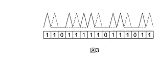
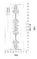
- the received signal is, for example, as shown in FIG. In the figure, the solid line represents the original received signal, and the broken line represents the received signal received with a delay. In this case, since a pulse is received at either of the first two pulse positions, it cannot be determined whether “0” is sent or “1” is sent. Similarly, in the third bit, the fourth bit, and the sixth bit, since the pulses are received at both the first half and the second half pulse positions, it cannot be demodulated correctly.
- Patent Document 1 is the conventional technique.
- a problem occurs. That is, when a delayed wave delayed by the time d shown in FIG. 1 is received in a superimposed manner, a pulse is also present at the same pulse position as when bit “0” is transmitted even though bit “1” is transmitted. Since it is received, it is impossible to determine whether “0” is sent or “1” is sent.
- data transmission is performed by changing the time position of the pulse by d j (k) (u) according to the transmission data. There is a possibility that the same pulse sequence as in the case of transmitting data different from that of the transmission data may be received in a superimposed manner, causing a reception error.
- an incoherent wireless communication method is a first means for modulating transmission data, and the modulated transmission data is pulsed.
- the second means for converting the received pulse into received data and the third means for demodulating the received data, the pulses used in the second means are composed of a plurality of pulse sequences, Is characterized in that the cross-correlation value peak is smaller than the auto-correlation value peak.
- a wireless communication device that uses an incoherent wireless communication method, a modulation unit that modulates transmission data, and a high frequency that converts transmission data modulated by the modulation unit into pulses and converts received pulses into reception data
- a demodulator for demodulating received data, and the pulses used in the high-frequency unit are composed of a plurality of pulse sequences, and the plurality of pulse sequences have a smaller cross-correlation value peak than an autocorrelation value peak. It is characterized by that.
- FIG. 9 is a diagram showing correlation characteristics of the pulse sequence of FIG.
- FIG. 15 is a diagram showing correlation characteristics of the pulse sequence of FIG.
- FIG. 15 is a diagram showing correlation characteristics of the pulse sequence of FIG.
- FIG. 6 is a view showing another example of correlation characteristics of a pulse sequence used in the 16-value modulator according to the present invention.
- FIG. 6 is a diagram showing another configuration example of the binary modulator according to the present invention.
- FIG. 6 is a diagram showing another configuration example of the quaternary modulator according to the present invention.
- FIG. 22 is a diagram illustrating an operation example of a converter used in the quaternary modulator of FIG.
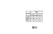
- FIG. 22 is a diagram showing an operation example of a converter when the quaternary modulator of FIG. 21 is used as a binary modulator.
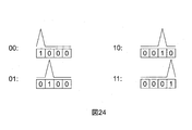
- FIG. 22 is a diagram showing an example of a 4-level PPM used in the 4-level modulator of FIG. FIG.
- FIG. 21 is a diagram showing an example of correlation characteristics of a pulse sequence output from the binary modulator of FIG.
- FIG. 22 is a diagram showing an example of correlation characteristics of a pulse sequence output from the quaternary modulator of FIG.
- FIG. 5 is a diagram showing communication between the wireless transceivers of FIG.
- the present invention provides a communication method in which transmission is performed using waveforms that are not similar to each other even when pulse waveforms when transmitting and receiving different data are shifted in time.
- the communication method according to the present invention configures a pulse sequence used for communication so that the cross-correlation between pulse waveforms when transmitting and receiving different data has a small correlation value.
- a method of preparing a plurality of randomly generated pulse sequences associated with data to be transmitted, selecting a sequence from the plurality of pulse sequences according to transmission data, and transmitting the same is conceivable.
- different random pulse sequences are transmitted.
- a transmission method is obtained.
- the cross-correlation between a plurality of pulse sequences and the received sequence is calculated, and it is determined that data associated with the sequence having the highest correlation has been transmitted.
- any of the cross-correlation values is set so that the cross-correlation between the pulse sequences A and B is sufficiently smaller than the auto-correlation values between the pulse sequences A and B. It is assumed that the pulse sequences A and B are configured so that the value of is less than 1/2 of the autocorrelation value.
- the cross-correlation value between the received pulse sequence A and the pulse sequence B is the pulse sequence Since it is less than the autocorrelation value of A, it can be demodulated without error.
- the error can be corrected by error correction, it goes without saying that the effect of the present invention can be obtained even if the cross-correlation value is larger than 1 ⁇ 2 of the autocorrelation value.
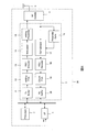
- FIG. 4 is an example of an overall configuration diagram of the wireless communication device 30 of the present embodiment.
- An interface unit 1 that exchanges transmission / reception signals with the outside, a processor 2 such as a CPU or DSP, and a baseband signal processing unit 3 are connected via a bus.
- the baseband signal processing unit 3 is connected to a high frequency (RF) unit 4.
- the high frequency (RF) unit 4 is connected to the antenna 5. Transmission data read by the processor 2 via the interface unit 1 is written to the transmission buffer 11.
- an FCS (Frame Check Sequence) adding unit 12 adds an error check code such as a CRC (Cyclic Redundancy Check) method.
- the error correction encoder 13 performs error correction encoding.
- the transmission data subjected to error correction coding is modulated by the modulator 14.
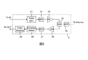
- FIG. 5 shows a configuration example of the high frequency (RF) unit 4 of this embodiment.
- Transmission data supplied from the baseband signal processing unit 3 is converted by the pulse generation unit 21 into a pulse train having a very narrow time width.
- the pulse train having an extremely narrow time width is supplied to a high output amplifier (PA) 23 after removing an unnecessary frequency band by a band pass filter (BPF: Band-pass Filter) 22 and shaping a spectrum shape.
- PA high output amplifier
- BPF Band-pass Filter
- the signal received by the antenna 5 has an unnecessary frequency band removed by a band-pass filter (BPF) 25 and is supplied to a low noise amplifier (LNA: Low Noise Amplifier) 26 via the antenna switch 24.
- LNA Low Noise Amplifier
- the received signal amplified by the low noise amplifier (LNA) 26 is again removed from the unnecessary frequency band by the bandpass filter (BPF) 27 and detected by the envelope detector 28.
- the received signal after detection is adjusted in pulse shape (waveform) by the pulse shaping unit 29 and supplied to the baseband signal processing unit 3.
- the modulated transmission data is added to the preamble by the preamble adding unit 15 and supplied to the radio frequency (RF) unit 4, converted into an ultra wideband (UWB) signal, and transmitted from the antenna 5.
- RF radio frequency
- UWB ultra wideband
- the signal received by the antenna 5 is converted into a baseband signal by the radio frequency (RF) unit 4 and supplied to the baseband signal processing unit 3.
- the baseband signal supplied from the radio frequency (RF) unit 4 is first subjected to preamble detection and timing extraction by the preamble synchronization unit 16.
- the demodulator 17 performs data demodulation processing according to the preamble timing detected by the preamble synchronization unit 16.
- the demodulated data is subjected to error correction by an error correction decoder 18.
- the FCS checking unit 19 checks whether or not all errors have been corrected by error correction using an error check code.
- the error check result and the decoded data are written in the reception buffer 20 and read by the processor 2.
- the received data read by the processor 2 is transmitted to the outside via the interface unit 1.
- the error check code used by the FCS adding unit 12 and the FCS checking unit 19 may be a so-called checksum instead of the CRC.
- the error correction code used in the error correction encoder 13 and the error correction decoder 16 is a general error such as Reed-Solomon code, BCH code, convolutional code, turbo code, LDPC (Low-density Parity-check) code.
- a correction code can be used.
- the preamble is preferably a pulse sequence that is known for both transmission and reception, and can obtain a sharp peak in autocorrelation characteristics. As a result, the receiving side can accurately and reliably narrow the preamble timing. Further, it is desirable that the preamble does not provide a large correlation with the modulation signal output from the modulator 14. Thereby, it is possible to prevent erroneous synchronization from occurring due to the transmission data portion. For example, a pulse sequence generated randomly may be used as such a characteristic.
- the modulator 14 can be configured as shown in FIG. 6, for example.
- the modulator of FIG. 6 has a modulation unit of 1 bit, and performs a binary modulation operation in which two types of pulse sequences S0 and S1 are selected and transmitted for each input bit. Two types of pulse sequences S0 and S1 are output from the pulse sequence generation units 101-a and 101-b.
- the pulse sequences output from the pulse sequence generators 101-a and 101-b are selected by the selector 102 and output from the modulator 14. At this time, the selector 102 selects the output S0 of the pulse sequence generation unit 101-a when the transmission data is 0, and the output S1 of the pulse sequence generation unit 101-b when the transmission data is 1. .
- the pulse sequences S0 and S1 as shown in FIG. 8 are used. That is, in both S0 and S1, six pulses are arranged at pseudo-random positions with respect to 32 positions where pulses can be arranged. Each pulse has only a single sign (positive in FIG. 8) so that it can be used for incoherent communication.
- FIG. 9 shows the autocorrelation characteristics between S0 and the cross-correlation characteristics between S0 and S1.
- the autocorrelation between S0s has a correlation value (vertical axis) of 6 at the right timing (the horizontal axis is 0), whereas the cross-correlation is the maximum for any time shift timing. 2
- N is the number of pulse positions where pulses can be placed
- P is the number of pulses to be placed
- M is the number of pulse sequences to be created
- K is the maximum allowable cross correlation value.
- the demodulator 17 calculates a correlation value between the received signal and the pulse sequences S0 and S1 based on the timing detected by the preamble synchronization unit 16, and demodulates the signal as a sequence from which a large correlation value was obtained. Do. That is, first, according to the timing detected by the preamble synchronization unit 16, the pulse sequences S0 and S1 are generated by the pulse sequence generation units 103-a and 103-b, respectively. The generated pulse sequences S0 and S1 are multiplied with the received signal by multipliers 104-a and 104-b, respectively.
- the pulse sequence S0, S1 is a binary value consisting of 0, 1
- the received signal is also a binary value such that it is 1 when there is a pulse and 0 when there is no pulse.
- a and 104-b are operations that output 1 when both inputs are 1 and 0 otherwise, they can be simply configured by logical product (AND) operation.
- the multiplication results are accumulated for the sequence length by accumulators 105-a and 105-b and output as correlation values. When the accumulation for the sequence length is completed, the correlation value is compared in the comparator 106, and 0 is output when the output of the accumulator 105-a is large, and 1 is output when the output of the accumulator 105-b is large. Output as demodulation result.
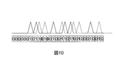
- FIG. 10 shows an example in which a delayed wave due to multipath is superimposed and received in addition to a direct wave during radio wave propagation.
- the delay amount of the delayed wave is three as the pulse position, the solid line represents the received pulse by the direct wave, and the broken line represents the received pulse by the delayed wave.
- the output of the pulse shaping unit 21 for the received signal on which both are superimposed is a series of 0 and 1 displayed with a frame in the lower part of FIG. FIG.
- the horizontal axis is 0, and when the delay wave timing is captured, the horizontal axis is the correlation value (vertical axis) of 3.
- the correlation value for the sequence 0 (S0) is 6
- the correlation value for the sequence 1 (S1) is 2, which indicates that the correlation value for the sequence 0 (S0) is large and can be demodulated correctly.
- the maximum value is 4, and there is no correlation value exceeding this.
- the wireless communication method described in the present embodiment includes a first step of modulating transmission data, a second step of converting the modulated transmission data into pulses, and converting a pulse received from the outside into reception data. And a third step for demodulating the received data, and the pulses used in the second step are composed of a plurality of pulse sequences, and the plurality of pulse sequences is a cross-correlation value rather than the peak of the autocorrelation value. Is characterized by a small peak.
- the radio communication device 30 described in the present embodiment includes a modulation unit that modulates transmission data, a high-frequency unit that converts transmission data modulated by the modulation unit into pulses, and converts pulses received from the outside into reception data; And a demodulator that demodulates received data, and the pulses used in the high-frequency unit are composed of a plurality of pulse sequences, and the plurality of pulse sequences have a cross-correlation value peak smaller than an autocorrelation value peak.
- a plurality of pulse sequences (S0, S1) generated randomly are prepared, and a pulse sequence to be transmitted is selected (102) according to the transmission data and output.
- the reception side performs a correlation operation between the plurality of pulse sequences (S0, S1) and the received signal and obtains a large correlation value, as shown in FIG.
- the communication method of performing reception using a demodulation method that determines that data corresponding to the data is transmitted can improve the resistance to multipath.
- the binary PPM transmission transmits 1 bit in 2 pulses time and 1 pulse. , 1 bit is transmitted in 6 pulses for 32 pulse times. That is, although the transmission rate is slower than that of binary PPM transmission, the energy allocated to 1-bit transmission is six times, and communication over a longer distance is possible than binary PPM transmission.
- the present embodiment uses a plurality of pulse sequences in which the cross-correlation value peak is smaller than the autocorrelation value peak, and each cross-correlation value is smaller than half the autocorrelation value peak. ing.
- the overall configuration of the radio communication device 30 is as shown in FIG. 4 and the radio frequency (RF) unit is already shown in FIG.
- FIG. 12 shows a configuration example of the modulator 14 in this embodiment.
- the modulator of FIG. 12 has a modulation unit of 2 bits, and performs a four-value modulation operation in which four types of pulse sequences S00, S01, S10, and S11 are selected and transmitted for every two input bits.
- the four types of pulse sequences S00, S01, S10, and S11 are output from the pulse sequence generation units 201-a, 201-b, 201-c, and 201-d, respectively.
- the pulse sequences output from the pulse sequence generators 201-a, 201-b, 201-c, and 201-d are selected by the selector 202 and output from the modulator 14.
- the selector 202 outputs the output S00 of the pulse sequence generation unit 201-a when the transmission data is “00”, and the output of the pulse sequence generation unit 201-b when the transmission data is “01”.
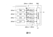
- the demodulator 17 calculates the correlation value between the received signal and the pulse sequences S00, S01, S10, ⁇ S11, and the sequence from which a large correlation value was obtained was transmitted Demodulate as a thing. That is, first, according to the timing detected by the preamble synchronization unit 16, the pulse sequences S00, S01, S10, and S11 are generated by the pulse sequence generation units 203-a, 203-b, 203-c, and 203-d, respectively.
- the generated pulse sequences S00, S01, S10, and S11 are multiplied by the received signal by multipliers 204-a, 204-b, 204-c, and 204-d, respectively.
- the multipliers 204-a, 204-b, 204-c, and 204-d can be simply configured by a logical product (AND) operation like the multipliers 104-a and 104-b of the first embodiment.
- the multiplication results are accumulated by the accumulators 205-a, 205-b, 205-c, and 205-d for the sequence length and output as correlation values. When the accumulation for the sequence length is completed, the correlation value is compared by the comparator 206.
- FIG. 14 shows a design example of the pulse sequences S00, S01, S10, and S11 used in the modulator shown in FIG. 12 and the demodulator shown in FIG.
- the correlation characteristics of the pulse sequence shown in FIG. 14 are shown in the table of FIG.
- the cross-correlation value between different series describes the maximum value obtained when the mutual time shifts are performed.
- Example 1 uses 32 pulse position times and 6 pulses for 1-bit transmission
- Example 2 uses 64 pulse times and 12 pulses for 2-bit transmission.
- the transmission rate and the transmission energy per bit are equal.
- the communication system of the present invention is a kind of M-ary system, it reflects the property that 4-ary transmission has higher noise immunity than 2-ary transmission, and thus has higher noise immunity than Example 1. It has the feature of being high.
- the cross correlation value peak is smaller than the auto correlation value peak, and each of the cross correlation values uses a plurality of pulse sequences smaller than 1/2 of the auto correlation value peak.
- the overall configuration of the wireless communication apparatus is as shown in FIG. 4 and the radio frequency (RF) unit is already shown in FIG.
- RF radio frequency
- a configuration example of the modulator 14 in the present embodiment is shown in FIG.
- the modulator of FIG. 16 has a modulation unit of 4 bits, and performs 16-value modulation operation in which 16 types of pulse sequences S0000 to S1111 are selected and transmitted for every 4 bits of input.
- the 16 types of pulse sequences S0000 to S1111 are output from the pulse sequence generators 301-a to 301-p, respectively.
- the pulse sequences output from the pulse sequence generators 301-a to 301-p are selected by the selector 302 and output from the modulator 14. At this time, the selector 302 selects and outputs the series S0000 to S1111 corresponding to the transmission data “0000” to “1111”.
- FIG. 17 shows a configuration example of the demodulator 17 in the present embodiment.
- the demodulator 17 calculates the correlation value between the received signal and the pulse sequence S0000 to S1111 based on the timing detected by the preamble synchronization unit 16, and demodulates the transmission as a sequence having a large correlation value. . That is, first, according to the timing detected by the preamble synchronization unit 16, the pulse sequences S0000 to S11 are generated by the pulse sequence generation units 303-a to 303-p, respectively. The generated pulse sequences S0000 to S1111 are multiplied by the received signals by multipliers 304-a to 304-p, respectively.
- the multipliers 304-a to 304-p can be simply configured by AND operation, similarly to the multipliers 104-a, 104-b, 204-a, 204-b, 204-c, and 204-d.
- the multiplication results are accumulated by the accumulators 305-a to 305-p for the sequence length and output as correlation values.
- the correlation value is compared by the comparator 306, the largest one of the outputs of the accumulators 305-a to 305-p is determined, and the corresponding is determined based on the determination. Demodulated data “0000” to “1111” are output as demodulation results.
- the correlation characteristics of the sequences obtained in this way are shown in the table of FIG.
- Example 2 uses 64 pulse position time and 12 pulses for 2-bit transmission, while Example 3 uses 128 pulse time and 24 pulses for 4-bit transmission.
- the transmission rate and the transmission energy per bit are equal.
- the communication system of the present invention is a kind of M-ary system, reflecting the property that 16-ary transmission has higher noise resistance than 4-ary transmission, it is more noise-resistant than Example 2. It is characterized by high.
- the design conditions are satisfied with a margin. For this reason, the possibility of an error due to multipath is further reduced.
- the communication method of the present invention can flexibly change the multipath tolerance and the transmittable distance by designing the pulse sequence. Therefore, it is also desirable to switch and use the pulse series used according to the communication environment.
- the cross-correlation value peak is smaller than the auto-correlation value peak, and the amount of cross-correlation value that can be corrected by error correction is a predetermined value of the autocorrelation value peak (this In the embodiment, a plurality of pulse sequences smaller than 1/2) are used.
- the overall configuration of the wireless communication apparatus is as shown in FIG. 4 and the radio frequency (RF) unit is already shown in FIG.
- FIG. 20 shows a configuration example of the modulator 14 in the present embodiment.
- the modulator in FIG. 20 has a modulation unit of 1 bit, and performs a binary modulation operation in which one of two types of pulse sequences is generated and transmitted for each input bit.
- the pseudo random number generator 401 generates a binary pseudo random number sequence.
- the binary pseudorandom number sequence is subjected to an exclusive OR operation with input data by an exclusive OR calculator 402.
- the result of the operation of the exclusive OR is subjected to binary PPM modulation as shown in FIG. Through the above operation, different random pulse sequences are generated when the input bit is 0 and when it is 1.
- a general random number generator such as an M-sequence generator can be used.
- the input data to the modulator 14 is updated every time a pulse sequence having a modulation pulse sequence length corresponding to a modulation unit is output.
- the random number sequence may be initialized for each modulation unit, or the pulse sequence may change one by one without initializing immediately after the preamble and initializing until the end of the frame.
- the demodulator 17 in this embodiment inputs the pulse sequences S0 and S1 generated by the pulse sequence generators 101-a and 101-b in the demodulator configuration shown in FIG. 7, and inputs 0 to the modulator in FIG.
- the modulation pulse sequence output in the case of 1 and the modulation pulse sequence output when 1 is input may be used.
- FIG. 25 shows an example of the correlation characteristics of the sequence generated by the modulator 14 of this embodiment.
- Corr (0,0) is the autocorrelation characteristic of the modulation pulse sequence (sequence 0) for input bit 0
- Corr (0,1) is the modulation pulse sequence (sequence 0) for input bit 0 and modulation for input bit 1.
- the cross-correlation value at time shift 0 where the autocorrelation peak of series 0 is obtained is 0, no matter what delay wave is superimposed, if it is a single wave, self-correlation
- the cross-correlation value is 24 at the maximum when the correlation peak value 32 is obtained. Therefore, the embodiment of the present invention does not generate a demodulation error due to multipath in an arbitrary two-wave multipath environment.
- the modulator 14 shown in the first embodiment it is also desirable to set a pulse sequence having such a property to S0 and S1.
- this embodiment also has a smaller cross-correlation value peak than the autocorrelation value peak, and the amount of cross-correlation value that can be corrected by error correction is a predetermined value of the autocorrelation value peak (this In the embodiment, a plurality of pulse sequences smaller than 1/2) are used.
- the overall configuration of the wireless communication apparatus is as shown in FIG. 4 and the radio frequency (RF) unit is already shown in FIG.
- FIG. 21 shows a configuration example of the modulator 14 in the present embodiment.
- the modulator in FIG. 21 has a modulation unit of 2 bits, and performs a four-value modulation operation in which one of four types of pulse sequences is generated and transmitted for every two input bits.
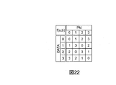
- the pseudo random number generator 501 generates a pseudo random number sequence of four values (00: 0, 01: 1, 10: 2, 11: 3).
- the quaternary pseudo-random number sequence is converted by the converter 502 according to the input data and output.
- the converter 502 performs the four values 0 (00), 1 (01), 2 (10), 3 (11) shown in the table of FIG. 22 for the pseudo random number sequence (PN) and the data input (DATA). ) Is output.
- the output of the converter 502 is subjected to 4-level PPM modulation as shown in FIG.
- the pseudo-random number generator 501 can be configured by using a general random number generator such as an M-sequence generator and outputting the output divided every two bits.
- the input data to the modulator 14 is updated every time a pulse sequence having a modulation pulse sequence length corresponding to a modulation unit is output, as in the fourth embodiment.
- the random number sequence may be initialized for each modulation unit, or the pulse sequence may change one by one without initializing immediately after the preamble and initializing until the end of the frame.
- the demodulator 17 in this embodiment uses the pulse sequences S00 to S11 generated by the pulse sequence generators 201-a to 201-d in the demodulator configuration shown in FIG. , 10, 11 may be used as the modulation pulse sequence that is output.
- FIG. 26 shows an example of the cross-correlation characteristics of the sequence generated by the modulator 14 of this embodiment.
- the notation of Corr (a, b) represents a cross-correlation characteristic between the modulation pulse sequence for the input bit a and the modulation pulse sequence for the input bit b.
- Incoherent UWB-IR communication with improved multipath tolerance can also be performed by performing modulation as shown in FIG. 6, FIG. 12, or FIG. 16 using a plurality of sequences.
- the maximum value of the cross-correlation value is smaller than the autocorrelation value, and most of the cross-correlation value is smaller than the autocorrelation value, for example, 1/2 or less of the cross-correlation value. Or, when multiple sequences such as 1/3 or less are used, the sum of the above condition, the cross-correlation value when the time shift is 0 and the maximum value of the cross-correlation value when the time shift is other than 0 Even if the value exceeds the autocorrelation value, the probability of generating a demodulation error due to multipath is very small, so that it is relieved by error correction, and as a result, high multipath tolerance can be realized.
- Interface part 2 Processor 3: Baseband signal processor 4: High frequency section 5: Antenna 11: Send buffer 12: FCS additional part 13: Error correction encoder 14: Modulator 15: Preamble addition part 16: Preamble synchronization part 17: Demodulator 18: Error correction decoder 19: FCS Inspection Department 20: Receive buffer 21: Pulse generator 22,25,27: Bandpass filter 23: High power amplifier (PA) 24: Antenna switch 26: Low noise amplifier (LNA) 28: Envelope detector 29: Pulse shaping section 30: Wireless communication device.
- PA High power amplifier
- LNA Low noise amplifier
Landscapes
- Engineering & Computer Science (AREA)
- Computer Networks & Wireless Communication (AREA)
- Signal Processing (AREA)
- Digital Transmission Methods That Use Modulated Carrier Waves (AREA)
- Dc Digital Transmission (AREA)
- Mobile Radio Communication Systems (AREA)
Priority Applications (3)
| Application Number | Priority Date | Filing Date | Title |
|---|---|---|---|
| JP2014506996A JP5900605B2 (ja) | 2012-03-28 | 2012-03-28 | マルチパス耐性を向上したインコヒーレントuwb−ir送受信方法 |
| US14/382,422 US9184790B2 (en) | 2012-03-28 | 2012-03-28 | Incoherent UWB-IR transceiving method with improved multipath-resistance |
| PCT/JP2012/002134 WO2013145003A1 (fr) | 2012-03-28 | 2012-03-28 | Procédé d'émission/réception uwb-ir incohérente avec résistance à chemins multiples améliorée |
Applications Claiming Priority (1)
| Application Number | Priority Date | Filing Date | Title |
|---|---|---|---|
| PCT/JP2012/002134 WO2013145003A1 (fr) | 2012-03-28 | 2012-03-28 | Procédé d'émission/réception uwb-ir incohérente avec résistance à chemins multiples améliorée |
Publications (1)
| Publication Number | Publication Date |
|---|---|
| WO2013145003A1 true WO2013145003A1 (fr) | 2013-10-03 |
Family
ID=49258378
Family Applications (1)
| Application Number | Title | Priority Date | Filing Date |
|---|---|---|---|
| PCT/JP2012/002134 Ceased WO2013145003A1 (fr) | 2012-03-28 | 2012-03-28 | Procédé d'émission/réception uwb-ir incohérente avec résistance à chemins multiples améliorée |
Country Status (3)
| Country | Link |
|---|---|
| US (1) | US9184790B2 (fr) |
| JP (1) | JP5900605B2 (fr) |
| WO (1) | WO2013145003A1 (fr) |
Families Citing this family (2)
| Publication number | Priority date | Publication date | Assignee | Title |
|---|---|---|---|---|
| JP6985610B2 (ja) * | 2018-07-10 | 2021-12-22 | 日本電信電話株式会社 | 無線通信装置及び無線信号受信方法 |
| DE102023135498A1 (de) * | 2023-12-18 | 2025-06-18 | Infineon Technologies Ag | Ultrabreitband-radargerät, verfahren zur autorisierung einer steueraktion und verfahren zur sicheren lokalisierung |
Citations (4)
| Publication number | Priority date | Publication date | Assignee | Title |
|---|---|---|---|---|
| WO2004077775A1 (fr) * | 2003-02-25 | 2004-09-10 | Yokohama Tlo Company, Ltd. | Procede pour produire des formes d'impulsion |
| JP2007082133A (ja) * | 2005-09-16 | 2007-03-29 | Samsung Electronics Co Ltd | 無線送信機および無線受信機 |
| JP2008010989A (ja) * | 2006-06-27 | 2008-01-17 | Yokohama National Univ | 送信信号形成方法及び送信信号形成装置 |
| WO2008139687A1 (fr) * | 2007-04-27 | 2008-11-20 | Panasonic Corporation | Instrument de mesure de forme et procédé de mesure de forme |
Family Cites Families (2)
| Publication number | Priority date | Publication date | Assignee | Title |
|---|---|---|---|---|
| KR100553884B1 (ko) | 2003-03-11 | 2006-02-24 | 삼성전자주식회사 | Uwb 펄스열 생성장치 및 방법, 그 펄스열을 사용한 무선 데이터 송수신 시스템, 무선 데이터 수신 장치 및 송수신 방법, 및 그 방법을 기록한 기록매체 |
| US20090041096A1 (en) * | 2007-08-02 | 2009-02-12 | Bae Systems Information And Electronic Systems Integration Inc. | Efficient synchronization of a spread spectrum signal in the presence of delay and frequency uncertainty |
-
2012
- 2012-03-28 JP JP2014506996A patent/JP5900605B2/ja not_active Expired - Fee Related
- 2012-03-28 WO PCT/JP2012/002134 patent/WO2013145003A1/fr not_active Ceased
- 2012-03-28 US US14/382,422 patent/US9184790B2/en not_active Expired - Fee Related
Patent Citations (4)
| Publication number | Priority date | Publication date | Assignee | Title |
|---|---|---|---|---|
| WO2004077775A1 (fr) * | 2003-02-25 | 2004-09-10 | Yokohama Tlo Company, Ltd. | Procede pour produire des formes d'impulsion |
| JP2007082133A (ja) * | 2005-09-16 | 2007-03-29 | Samsung Electronics Co Ltd | 無線送信機および無線受信機 |
| JP2008010989A (ja) * | 2006-06-27 | 2008-01-17 | Yokohama National Univ | 送信信号形成方法及び送信信号形成装置 |
| WO2008139687A1 (fr) * | 2007-04-27 | 2008-11-20 | Panasonic Corporation | Instrument de mesure de forme et procédé de mesure de forme |
Non-Patent Citations (1)
| Title |
|---|
| KAZUKI ESHIMA ET AL.: "M-ary Impulse Radio (UWB) with Interference Canceller for Multi- user Environment", IEICE TECHNICAL REPORT, CS, TSUSHIN HOSHIKI 101(30), 20 April 2001 (2001-04-20), pages 41 - 48 * |
Also Published As
| Publication number | Publication date |
|---|---|
| JP5900605B2 (ja) | 2016-04-06 |
| US9184790B2 (en) | 2015-11-10 |
| JPWO2013145003A1 (ja) | 2015-08-03 |
| US20150098491A1 (en) | 2015-04-09 |
Similar Documents
| Publication | Publication Date | Title |
|---|---|---|
| CN100483958C (zh) | 高数据率无线局域网络的通信方法 | |
| US5761239A (en) | Method and apparatus for despreading spread spectrum signals | |
| US5809060A (en) | High-data-rate wireless local-area network | |
| US8699471B2 (en) | System and method for scrambling and time-hopping | |
| CN100512072C (zh) | 利用发送参考前同步信号实现超宽带通信中的同步 | |
| EP0949765A2 (fr) | Sytème de modulation numérique avec ensemble étendu de codes | |
| US20100278214A1 (en) | Pulse-level interleaving for UWB systems | |
| US20030076898A1 (en) | Digital modulation system using extended code set | |
| CN101946474A (zh) | 脉冲超宽带无线电通信系统 | |
| US8605770B2 (en) | Ultra wideband modulation for body area networks | |
| CN113242087B (zh) | 一种基于复合码的测距与通信融合传输方法 | |
| KR101176214B1 (ko) | 데이터 변조방법 및 복조방법 | |
| US10536188B2 (en) | Signal processing method and transmitter and receiver | |
| US20040142663A1 (en) | Method for operating multiple overlapping wireless networks | |
| US7280601B2 (en) | Method for operating multiple overlapping wireless networks | |
| JP5900605B2 (ja) | マルチパス耐性を向上したインコヒーレントuwb−ir送受信方法 | |
| CN110113280A (zh) | 一种猝发通信中抗频偏的gmsk解调同步方法 | |
| JP2008533755A (ja) | ワイヤレス通信ネットワークにおいてビットの系列をM−ary変調する方法 | |
| JP4885854B2 (ja) | ワイヤレス通信ネットワークにおいてビットの系列を変調する方法及び変調器 | |
| KR100911727B1 (ko) | 듀얼 모드형 전력선 통신 시스템 | |
| JP2004072589A (ja) | 超広帯域(uwb)送信装置及び超広帯域(uwb)受信装置 | |
| Kreiser et al. | Improvements of IEEE 802.15. 4a for non-coherent energy detection receiver | |
| US20100226414A1 (en) | System and a Method for Wireless Transmission and Reception of Concatenated Impulse Radio Ultra-Wideband Data Bursts | |
| CN114665918B (zh) | 一种具有纠错能力的多斜率Chirp信号生成及解扩方法 | |
| Olonbayar et al. | Performance and design of IR-UWB transceiver baseband for wireless sensors |
Legal Events
| Date | Code | Title | Description |
|---|---|---|---|
| 121 | Ep: the epo has been informed by wipo that ep was designated in this application |
Ref document number: 12872958 Country of ref document: EP Kind code of ref document: A1 |
|
| ENP | Entry into the national phase |
Ref document number: 2014506996 Country of ref document: JP Kind code of ref document: A |
|
| WWE | Wipo information: entry into national phase |
Ref document number: 14382422 Country of ref document: US |
|
| NENP | Non-entry into the national phase |
Ref country code: DE |
|
| 122 | Ep: pct application non-entry in european phase |
Ref document number: 12872958 Country of ref document: EP Kind code of ref document: A1 |