WO2013145096A1 - Dispositif de commande d'entraînement de véhicule hybride - Google Patents
Dispositif de commande d'entraînement de véhicule hybride Download PDFInfo
- Publication number
- WO2013145096A1 WO2013145096A1 PCT/JP2012/057815 JP2012057815W WO2013145096A1 WO 2013145096 A1 WO2013145096 A1 WO 2013145096A1 JP 2012057815 W JP2012057815 W JP 2012057815W WO 2013145096 A1 WO2013145096 A1 WO 2013145096A1
- Authority
- WO
- WIPO (PCT)
- Prior art keywords
- engine
- electric motor
- rotating element
- differential mechanism
- clutch
- Prior art date
- Legal status (The legal status is an assumption and is not a legal conclusion. Google has not performed a legal analysis and makes no representation as to the accuracy of the status listed.)
- Ceased
Links
Images








Classifications
-
- B—PERFORMING OPERATIONS; TRANSPORTING
- B60—VEHICLES IN GENERAL
- B60K—ARRANGEMENT OR MOUNTING OF PROPULSION UNITS OR OF TRANSMISSIONS IN VEHICLES; ARRANGEMENT OR MOUNTING OF PLURAL DIVERSE PRIME-MOVERS IN VEHICLES; AUXILIARY DRIVES FOR VEHICLES; INSTRUMENTATION OR DASHBOARDS FOR VEHICLES; ARRANGEMENTS IN CONNECTION WITH COOLING, AIR INTAKE, GAS EXHAUST OR FUEL SUPPLY OF PROPULSION UNITS IN VEHICLES
- B60K6/00—Arrangement or mounting of plural diverse prime-movers for mutual or common propulsion, e.g. hybrid propulsion systems comprising electric motors and internal combustion engines
- B60K6/20—Arrangement or mounting of plural diverse prime-movers for mutual or common propulsion, e.g. hybrid propulsion systems comprising electric motors and internal combustion engines the prime-movers consisting of electric motors and internal combustion engines, e.g. HEVs
- B60K6/42—Arrangement or mounting of plural diverse prime-movers for mutual or common propulsion, e.g. hybrid propulsion systems comprising electric motors and internal combustion engines the prime-movers consisting of electric motors and internal combustion engines, e.g. HEVs characterised by the architecture of the hybrid electric vehicle
- B60K6/44—Series-parallel type
- B60K6/445—Differential gearing distribution type
-
- B—PERFORMING OPERATIONS; TRANSPORTING
- B60—VEHICLES IN GENERAL
- B60K—ARRANGEMENT OR MOUNTING OF PROPULSION UNITS OR OF TRANSMISSIONS IN VEHICLES; ARRANGEMENT OR MOUNTING OF PLURAL DIVERSE PRIME-MOVERS IN VEHICLES; AUXILIARY DRIVES FOR VEHICLES; INSTRUMENTATION OR DASHBOARDS FOR VEHICLES; ARRANGEMENTS IN CONNECTION WITH COOLING, AIR INTAKE, GAS EXHAUST OR FUEL SUPPLY OF PROPULSION UNITS IN VEHICLES
- B60K6/00—Arrangement or mounting of plural diverse prime-movers for mutual or common propulsion, e.g. hybrid propulsion systems comprising electric motors and internal combustion engines
- B60K6/20—Arrangement or mounting of plural diverse prime-movers for mutual or common propulsion, e.g. hybrid propulsion systems comprising electric motors and internal combustion engines the prime-movers consisting of electric motors and internal combustion engines, e.g. HEVs
- B60K6/22—Arrangement or mounting of plural diverse prime-movers for mutual or common propulsion, e.g. hybrid propulsion systems comprising electric motors and internal combustion engines the prime-movers consisting of electric motors and internal combustion engines, e.g. HEVs characterised by apparatus, components or means specially adapted for HEVs
- B60K6/38—Arrangement or mounting of plural diverse prime-movers for mutual or common propulsion, e.g. hybrid propulsion systems comprising electric motors and internal combustion engines the prime-movers consisting of electric motors and internal combustion engines, e.g. HEVs characterised by apparatus, components or means specially adapted for HEVs characterised by the driveline clutches
- B60K6/387—Actuated clutches, i.e. clutches engaged or disengaged by electric, hydraulic or mechanical actuating means
-
- B—PERFORMING OPERATIONS; TRANSPORTING
- B60—VEHICLES IN GENERAL
- B60W—CONJOINT CONTROL OF VEHICLE SUB-UNITS OF DIFFERENT TYPE OR DIFFERENT FUNCTION; CONTROL SYSTEMS SPECIALLY ADAPTED FOR HYBRID VEHICLES; ROAD VEHICLE DRIVE CONTROL SYSTEMS FOR PURPOSES NOT RELATED TO THE CONTROL OF A PARTICULAR SUB-UNIT
- B60W10/00—Conjoint control of vehicle sub-units of different type or different function
- B60W10/04—Conjoint control of vehicle sub-units of different type or different function including control of propulsion units
- B60W10/06—Conjoint control of vehicle sub-units of different type or different function including control of propulsion units including control of combustion engines
-
- B—PERFORMING OPERATIONS; TRANSPORTING
- B60—VEHICLES IN GENERAL
- B60W—CONJOINT CONTROL OF VEHICLE SUB-UNITS OF DIFFERENT TYPE OR DIFFERENT FUNCTION; CONTROL SYSTEMS SPECIALLY ADAPTED FOR HYBRID VEHICLES; ROAD VEHICLE DRIVE CONTROL SYSTEMS FOR PURPOSES NOT RELATED TO THE CONTROL OF A PARTICULAR SUB-UNIT
- B60W20/00—Control systems specially adapted for hybrid vehicles
- B60W20/50—Control strategies for responding to system failures, e.g. for fault diagnosis, failsafe operation or limp mode
-
- B—PERFORMING OPERATIONS; TRANSPORTING
- B60—VEHICLES IN GENERAL
- B60K—ARRANGEMENT OR MOUNTING OF PROPULSION UNITS OR OF TRANSMISSIONS IN VEHICLES; ARRANGEMENT OR MOUNTING OF PLURAL DIVERSE PRIME-MOVERS IN VEHICLES; AUXILIARY DRIVES FOR VEHICLES; INSTRUMENTATION OR DASHBOARDS FOR VEHICLES; ARRANGEMENTS IN CONNECTION WITH COOLING, AIR INTAKE, GAS EXHAUST OR FUEL SUPPLY OF PROPULSION UNITS IN VEHICLES
- B60K6/00—Arrangement or mounting of plural diverse prime-movers for mutual or common propulsion, e.g. hybrid propulsion systems comprising electric motors and internal combustion engines
- B60K6/20—Arrangement or mounting of plural diverse prime-movers for mutual or common propulsion, e.g. hybrid propulsion systems comprising electric motors and internal combustion engines the prime-movers consisting of electric motors and internal combustion engines, e.g. HEVs
- B60K6/22—Arrangement or mounting of plural diverse prime-movers for mutual or common propulsion, e.g. hybrid propulsion systems comprising electric motors and internal combustion engines the prime-movers consisting of electric motors and internal combustion engines, e.g. HEVs characterised by apparatus, components or means specially adapted for HEVs
- B60K6/38—Arrangement or mounting of plural diverse prime-movers for mutual or common propulsion, e.g. hybrid propulsion systems comprising electric motors and internal combustion engines the prime-movers consisting of electric motors and internal combustion engines, e.g. HEVs characterised by apparatus, components or means specially adapted for HEVs characterised by the driveline clutches
- B60K2006/381—Arrangement or mounting of plural diverse prime-movers for mutual or common propulsion, e.g. hybrid propulsion systems comprising electric motors and internal combustion engines the prime-movers consisting of electric motors and internal combustion engines, e.g. HEVs characterised by apparatus, components or means specially adapted for HEVs characterised by the driveline clutches characterized by driveline brakes
-
- Y—GENERAL TAGGING OF NEW TECHNOLOGICAL DEVELOPMENTS; GENERAL TAGGING OF CROSS-SECTIONAL TECHNOLOGIES SPANNING OVER SEVERAL SECTIONS OF THE IPC; TECHNICAL SUBJECTS COVERED BY FORMER USPC CROSS-REFERENCE ART COLLECTIONS [XRACs] AND DIGESTS
- Y02—TECHNOLOGIES OR APPLICATIONS FOR MITIGATION OR ADAPTATION AGAINST CLIMATE CHANGE
- Y02T—CLIMATE CHANGE MITIGATION TECHNOLOGIES RELATED TO TRANSPORTATION
- Y02T10/00—Road transport of goods or passengers
- Y02T10/60—Other road transportation technologies with climate change mitigation effect
- Y02T10/62—Hybrid vehicles
Definitions
- the present invention relates to an improvement of a drive control device for a hybrid vehicle.
- a hybrid vehicle including at least one electric motor that functions as a drive source is known.
- this is the vehicle described in Patent Document 1.
- the brake is provided to fix the output shaft of the internal combustion engine to the non-rotating member, and according to the traveling state of the vehicle. By controlling the engagement state of the brake, it is possible to improve the energy efficiency of the vehicle and to travel according to the driver's request.
- JP 2008-265600 A Japanese Patent No. 4038183
- the present invention has been made against the background of the above circumstances, and an object of the present invention is to provide a drive control device for a hybrid vehicle that realizes a suitable retreat during engine failure.
- the gist of the first aspect of the present invention is that a first differential mechanism and a second differential mechanism having four rotating elements as a whole, and these four rotating elements are respectively connected.
- An element is selectively connected via a clutch, and the rotating element of the first differential mechanism or the second differential mechanism to be engaged by the clutch is selected via a brake for a non-rotating member.
- the hybrid vehicle drive control device is characterized in that the output shaft of the engine is non-rotating when the engine fails.
- the first differential mechanism and the second differential mechanism having four rotating elements as a whole, and the engine, the first electric motor, the second electric motor, and the engine respectively connected to the four rotating elements, and An output rotating member, wherein one of the four rotating elements is selectively connected to the rotating element of the first differential mechanism and the rotating element of the second differential mechanism via a clutch.
- the rotating element of the first differential mechanism or the second differential mechanism to be engaged by the clutch is selectively connected to a non-rotating member via a brake. Since the output shaft of the engine is not rotated at the time of failure of the engine, the retreat travel is performed using the driving force of at least one of the first electric motor and the second electric motor at the time of failure of the engine.
- a drive control device for a hybrid vehicle that realizes suitable retreat travel during engine failure.
- the gist of the second invention which is dependent on the first invention, is that the engine output shaft is fixed to the non-rotating member by engaging both the clutch and the brake when the engine fails. Is. In this way, the engine output shaft can be made non-rotating in a practical manner during the engine failure.
- the gist of the third invention subordinate to the first to second inventions is that the first differential mechanism includes a first rotating element connected to the first electric motor and a first rotating element connected to the engine.
- a second rotating element coupled to the output rotating member, and the second differential mechanism includes a first rotating element coupled to the second electric motor, a second rotating element, And a third rotating element, and either one of the second rotating element or the third rotating element is connected to the third rotating element in the first differential mechanism, and the clutch has the first difference.
- a second rotating element in the moving mechanism and a rotating element not connected to the third rotating element in the first differential mechanism among the second rotating element and the third rotating element in the second differential mechanism are selected.
- the brake is Of the second rotating element and the third rotating element in the second differential mechanism, the rotating element that is not connected to the third rotating element in the first differential mechanism is selectively selected with respect to the non-rotating member. To be engaged. If it does in this way, in the hybrid vehicle drive device of a practical aspect, it is possible to realize suitable retreat travel during engine failure.
- FIG. 1 is a skeleton diagram illustrating a configuration of a hybrid vehicle drive device to which the present invention is preferably applied. It is a figure explaining the principal part of the control system provided in order to control the drive of the drive device of FIG.
- FIG. 2 is an engagement table showing clutch and brake engagement states in each of five types of travel modes established in the drive device of FIG. 1.
- FIG. 4 is a collinear diagram that can represent the relative relationship of the rotational speeds of the respective rotary elements on a straight line in the drive device of FIG. 1, and is a diagram corresponding to modes 1 and 3 of FIG. 3.
- FIG. 1 is a skeleton diagram illustrating a configuration of a hybrid vehicle drive device to which the present invention is preferably applied. It is a figure explaining the principal part of the control system provided in order to control the drive of the drive device of FIG.
- FIG. 2 is an engagement table showing clutch and brake engagement states in each of five types of travel modes established in the drive device of FIG. 1.
- FIG. 4 is a collinear diagram
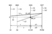
- FIG. 4 is a collinear diagram that can represent the relative relationship of the rotation speeds of the respective rotary elements on a straight line in the drive device of FIG. 1, corresponding to mode 2 of FIG. 3.
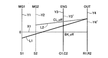
- FIG. 4 is a collinear diagram that can represent the relative relationship of the rotational speeds of the respective rotary elements on a straight line in the drive device of FIG. 1, corresponding to mode 4 of FIG. 3.
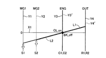
- FIG. 4 is a collinear diagram that can represent the relative relationship of the rotational speeds of the respective rotary elements on a straight line in the drive device of FIG. 1, corresponding to mode 5 of FIG. 3. It is a functional block diagram explaining the principal part of the control function with which the electronic control apparatus of FIG. 2 was equipped. In the drive device of FIG.
- FIG. 2 is a collinear diagram that can represent on a straight line the relative relationship between the rotational speeds of the rotating elements in the drive device of FIG.
- FIG. 2 is a collinear diagram that can represent the relative relationship of the rotation speeds of the respective rotary elements on a straight line in the drive device of FIG.
- It is a flowchart explaining the principal part of an example of retreat travel control at the time of engine failure by the electronic controller of FIG.
- It is a skeleton diagram explaining the composition of the other hybrid vehicle drive device to which the present invention is applied suitably.
- It is a skeleton diagram explaining the composition of still another hybrid vehicle drive device to which the present invention is preferably applied.
- FIG. 6 is a collinear diagram illustrating the configuration and operation of still another hybrid vehicle drive device to which the present invention is preferably applied.
- FIG. 6 is a collinear diagram illustrating the configuration and operation of still another hybrid vehicle drive device to which the present invention is preferably applied.
- FIG. 6 is a collinear diagram illustrating the configuration and operation of still another hybrid vehicle drive device to which the present invention is preferably applied.
- FIG. 6 is a collinear diagram illustrating the configuration and operation of still another hybrid vehicle drive device to which the present invention is preferably applied.
- FIG. 6 is a collinear diagram illustrating the configuration and operation of still another hybrid vehicle drive device to which the present invention is preferably applied.
- FIG. 6 is a collinear diagram illustrating the configuration and operation of still another hybrid vehicle drive device to which the present invention is preferably applied.
- the first differential mechanism and the second differential mechanism have four rotation elements as a whole when the clutch is engaged.
- the first differential mechanism and the second differential mechanism are: In the state in which the plurality of clutches are engaged, there are four rotating elements as a whole.
- the present invention relates to a first differential mechanism and a second differential mechanism that are represented as four rotating elements on the nomographic chart, an engine connected to each of the four rotating elements, a first electric motor, A second electric motor, and an output rotating member, wherein one of the four rotating elements includes a rotating element of the first differential mechanism and a rotating element of the second differential mechanism via a clutch.
- a hybrid vehicle that is selectively connected and a rotating element of the first differential mechanism or the second differential mechanism that is to be engaged by the clutch is selectively connected to a non-rotating member via a brake. It is suitably applied to the drive control apparatus.
- the clutch and the brake are preferably hydraulic engagement devices whose engagement state is controlled (engaged or released) according to the hydraulic pressure, for example, a wet multi-plate friction engagement device.
- a meshing engagement device that is, a so-called dog clutch (meshing clutch) may be used.
- the engagement state may be controlled (engaged or released) according to an electrical command, such as an electromagnetic clutch or a magnetic powder clutch.
- one of a plurality of travel modes is selectively established according to the engagement state of the clutch and the brake.
- the operation of the engine is stopped and the brake is engaged and the clutch is released in an EV traveling mode in which at least one of the first electric motor and the second electric motor is used as a driving source for traveling.
- mode 1 is established
- mode 2 is established by engaging both the brake and the clutch.
- the mode is set when the brake is engaged and the clutch is released.
- Mode 4 is established when the brake is released and the clutch is engaged
- mode 5 is established when both the brake and the clutch are released.
- each rotating element in each of the first differential mechanism and the second differential mechanism when the clutch is engaged and the brake is released.
- the arrangement order indicates the first rotation in the first differential mechanism when the rotation speeds corresponding to the second rotation element and the third rotation element in each of the first differential mechanism and the second differential mechanism are superimposed.
- FIG. 1 is a skeleton diagram illustrating the configuration of a hybrid vehicle drive device 10 (hereinafter simply referred to as drive device 10) to which the present invention is preferably applied.
- the drive device 10 of the present embodiment is a device for horizontal use that is preferably used in, for example, an FF (front engine front wheel drive) type vehicle and the like, and an engine 12, which is a main power source,
- the first electric motor MG1, the second electric motor MG2, the first planetary gear device 14 as a first differential mechanism, and the second planetary gear device 16 as a second differential mechanism are provided on a common central axis CE.
- the driving device 10 is configured substantially symmetrically with respect to the central axis CE, and the lower half of the central line is omitted in FIG. The same applies to each of the following embodiments.
- the engine 12 is, for example, an internal combustion engine such as a gasoline engine that generates driving force by combustion of fuel such as gasoline injected in a cylinder.
- the first electric motor MG1 and the second electric motor MG2 are preferably so-called motor generators each having a function as a motor (engine) for generating driving force and a generator (generator) for generating reaction force.
- Each stator (stator) 18, 22 is fixed to a housing (case) 26 that is a non-rotating member, and the rotor (rotor) 20, 24 is provided on the inner peripheral side of each stator 18, 22. Has been.
- the first planetary gear unit 14 is a single pinion type planetary gear unit having a gear ratio of ⁇ 1, and serves as a second rotating element that supports the sun gear S1 and the pinion gear P1 as the first rotating element so as to be capable of rotating and revolving.
- a ring gear R1 as a third rotating element that meshes with the sun gear S1 via the carrier C1 and the pinion gear P1 is provided as a rotating element (element).
- the second planetary gear device 16 is a single pinion type planetary gear device having a gear ratio of ⁇ 2, and serves as a second rotating element that supports the sun gear S2 and the pinion gear P2 as the first rotating element so as to be capable of rotating and revolving.
- a ring gear R2 as a third rotating element that meshes with the sun gear S2 via the carrier C2 and the pinion gear P2 is provided as a rotating element (element).
- the sun gear S1 of the first planetary gear unit 14 is connected to the rotor 20 of the first electric motor MG1.
- the carrier C1 of the first planetary gear unit 14 is connected to an input shaft 28 that is rotated integrally with the crankshaft of the engine 12.
- the input shaft 28 is centered on the central axis CE.
- the direction of the central axis of the central axis CE is referred to as an axial direction (axial direction) unless otherwise distinguished.
- the ring gear R1 of the first planetary gear device 14 is connected to an output gear 30 that is an output rotating member, and is also connected to the ring gear R2 of the second planetary gear device 16.
- the sun gear S2 of the second planetary gear device 16 is connected to the rotor 24 of the second electric motor MG2.
- the driving force output from the output gear 30 is transmitted to a pair of left and right driving wheels (not shown) via a differential gear device and an axle (not shown).
- torque input to the drive wheels from the road surface of the vehicle is transmitted (input) from the output gear 30 to the drive device 10 via the differential gear device and the axle.
- a mechanical oil pump 32 such as a vane pump is connected to an end portion of the input shaft 28 opposite to the engine 12, and an original pressure of a hydraulic control circuit 60 or the like to be described later when the engine 12 is driven.
- the hydraulic pressure is output.
- the driving device 10 is provided with an electric oil pump 33 (see FIG. 2) which is an electric oil pump driven by electric energy supplied from a battery (not shown), for example.
- the hydraulic pressure output from the electric oil pump 33 is supplied as a source pressure of the hydraulic control circuit 60 and the like.
- the carrier C1 of the first planetary gear device 14 and the carrier C2 of the second planetary gear device 16 are selectively engaged between the carriers C1 and C2 (between the carriers C1 and C2).
- a clutch CL is provided.
- a brake BK for selectively engaging (fixing) the carrier C2 with respect to the housing 26 is provided between the carrier C2 of the second planetary gear device 16 and the housing 26 which is a non-rotating member.
- the clutch CL and the brake BK are preferably hydraulic engagement devices whose engagement states are controlled (engaged or released) according to the hydraulic pressure supplied from the hydraulic control circuit 60.
- a wet multi-plate friction engagement device or the like is preferably used, but a meshing engagement device, that is, a so-called dog clutch (meshing clutch) may be used.
- an engagement state may be controlled (engaged or released) according to an electrical command supplied from the electronic control device 40, such as an electromagnetic clutch or a magnetic powder clutch.
- the first planetary gear device 14 and the second planetary gear device 16 are arranged coaxially with the input shaft 28 (on the central axis CE), and , Are arranged at positions facing each other in the axial direction of the central axis CE. That is, with respect to the axial direction of the central axis CE, the first planetary gear device 14 is disposed on the engine 12 side with respect to the second planetary gear device 16. With respect to the axial direction of the central axis CE, the first electric motor MG1 is disposed on the engine 12 side with respect to the first planetary gear unit 14.
- the second electric motor MG1 is disposed on the opposite side of the engine 12 with respect to the second planetary gear device 16. That is, the first electric motor MG1 and the second electric motor MG2 are arranged at positions facing each other with the first planetary gear device 14 and the second planetary gear device 16 interposed therebetween with respect to the axial direction of the central axis CE. . That is, in the drive device 10, in the axial direction of the central axis CE, the first electric motor MG1, the first planetary gear device 14, the clutch CL, the second planetary gear device 16, the brake BK, Those components are arranged on the same axis in the order of the two electric motors MG2.
- FIG. 2 is a diagram for explaining a main part of a control system provided in the driving device 10 in order to control the driving of the driving device 10.
- the electronic control unit 40 shown in FIG. 2 includes a CPU, a ROM, a RAM, an input / output interface, and the like, and executes signal processing in accordance with a program stored in advance in the ROM while using a temporary storage function of the RAM.
- the microcomputer is a so-called microcomputer, and executes various controls related to driving of the drive device 10 including drive control of the engine 12 and hybrid drive control related to the first electric motor MG1 and the second electric motor MG2. That is, in this embodiment, the electronic control device 40 corresponds to a drive control device for a hybrid vehicle to which the drive device 10 is applied.
- the electronic control device 40 is configured as an individual control device for each control as required, such as for output control of the engine 12 and for operation control of the first electric motor MG1 and the second electric motor MG2.
- the electronic control device 40 is configured to be supplied with various signals from sensors, switches, and the like provided in each part of the driving device 10. That is, a signal representing an accelerator opening degree A CC which is an operation amount of an accelerator pedal (not shown) corresponding to a driver's output request amount by the accelerator opening sensor 42, and an engine which is the rotation speed of the engine 12 by the engine rotation speed sensor 44.
- a signal representing an accelerator opening degree A CC which is an operation amount of an accelerator pedal (not shown) corresponding to a driver's output request amount by the accelerator opening sensor 42
- an engine which is the rotation speed of the engine 12 by the engine rotation speed sensor 44.
- the electronic control device 40 is configured to output an operation command to each part of the driving device 10. That is, as an engine output control command for controlling the output of the engine 12, a fuel injection amount signal for controlling a fuel supply amount to an intake pipe or the like by the fuel injection device, and an ignition timing (ignition timing) of the engine 12 by the ignition device.
- An ignition signal to be commanded, an electronic throttle valve drive signal supplied to the throttle actuator for operating the throttle valve opening ⁇ TH of the electronic throttle valve, and the like are output to an engine control device 56 that controls the output of the engine 12.
- the A command signal for commanding the operation of the first motor MG1 and the second motor MG2 is output to the inverter 58, and electric energy corresponding to the command signal is transmitted from the battery via the inverter 58 to the first motor MG1 and the second motor.
- the output (torque) of the first electric motor MG1 and the second electric motor MG2 is controlled by being supplied to MG2.
- Electric energy generated by the first electric motor MG1 and the second electric motor MG2 is supplied to the battery via the inverter 58 and stored in the battery.
- a command signal for controlling the engagement state of the clutch CL and the brake BK is supplied to an electromagnetic control valve such as a linear solenoid valve provided in the hydraulic control circuit 60, and the hydraulic pressure output from the electromagnetic control valve is controlled.
- a command signal for commanding the operation of the electric oil pump 33 is output to the electric oil pump 33, and the presence / absence of operation of the electric oil pump 33, the output hydraulic pressure (discharge amount), and the like are controlled.
- the drive device 10 functions as an electric differential unit that controls the differential state between the input rotation speed and the output rotation speed by controlling the operation state via the first electric motor MG1 and the second electric motor MG2.
- the electric energy generated by the first electric motor MG1 is supplied to the battery and the second electric motor MG2 via the inverter 58.
- the main part of the power of the engine 12 is mechanically transmitted to the output gear 30, while a part of the power is consumed for power generation of the first electric motor MG 1 and is converted into electric energy there.
- the electric energy is supplied to the second electric motor MG2 through the inverter 58.
- the second electric motor MG2 is driven, and the power output from the second electric motor MG2 is transmitted to the output gear 30.
- Electrical path from conversion of part of the power of the engine 12 into electrical energy and conversion of the electrical energy into mechanical energy by related equipment from the generation of the electrical energy to consumption by the second electric motor MG2. Is configured.
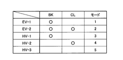
- FIG. 3 is an engagement table showing the engagement states of the clutch CL and the brake BK in each of the five types of travel modes established in the drive device 10, wherein the engagement is “ ⁇ ” and the release is blank. Show. In each of the travel modes “EV-1” and “EV-2” shown in FIG. 3, the operation of the engine 12 is stopped, and at least one of the first electric motor MG1 and the second electric motor MG2 is used for traveling. This is an EV travel mode used as a drive source.
- HV-1”, “HV-2”, and “HV-3” all drive the engine 12 as a driving source for traveling, for example, and the first motor MG1 and the second motor MG2 as required.
- This is a hybrid travel mode for driving or generating power.
- a reaction force may be generated by at least one of the first electric motor MG1 and the second electric motor MG2, or may be idled in an unloaded state.
- the operation of the engine 12 is stopped, and in the EV traveling mode in which at least one of the first electric motor MG ⁇ b> 1 and the second electric motor MG ⁇ b> 2 is used as a driving source for traveling.
- mode 1 travel mode 1
- 2 travel mode 2
- the brake BK is engaged.
- HV-1 which is mode 3 (travel mode 3) by releasing the clutch CL
- mode 4 travel mode 4
- HV-2 is established
- HV-3 which is mode 5 (travel mode 5) is established by releasing both the brake BK and the clutch CL.
- FIGS. 4 to 7 show the rotation elements of the driving device 10 (the first planetary gear device 14 and the second planetary gear device 16) that have different coupling states depending on the engagement states of the clutch CL and the brake BK.
- FIG. 2 shows a collinear chart that can represent the relative relationship of rotational speed on a straight line, showing the relative relationship of the gear ratio ⁇ of the first planetary gear device 14 and the second planetary gear device 16 in the horizontal axis direction, It is a two-dimensional coordinate which shows a relative rotational speed in an axial direction.
- the rotational speeds of the output gears 30 when the vehicle moves forward are represented as positive directions (positive rotations).
- a horizontal line X1 indicates zero rotation speed.
- the solid line Y1 indicates the sun gear S1 (first electric motor MG1) of the first planetary gear unit 14, the broken line Y2 indicates the sun gear S2 (second electric motor MG2) of the second planetary gear unit 16,
- the solid line Y3 is the carrier C1 (engine 12) of the first planetary gear unit 14, the broken line Y3 'is the carrier C2 of the second planetary gear unit 16, and the solid line Y4 is the ring gear R1 (output gear 30) of the first planetary gear unit 14.
- the broken line Y4 ′ indicates the relative rotational speed of each ring gear R2 of the second planetary gear unit 16.
- the relative rotational speeds of the three rotating elements in the first planetary gear device 14 are indicated by a solid line L1
- the relative rotational speeds of the three rotating elements in the second planetary gear device 16 are indicated by solid lines L1.
- Each is indicated by a broken line L2.
- the intervals between the vertical lines Y1 to Y4 (Y2 to Y4 ′) are determined according to the gear ratios ⁇ 1 and ⁇ 2 of the first planetary gear device 14 and the second planetary gear device 16. That is, regarding the vertical lines Y1, Y3, Y4 corresponding to the three rotating elements in the first planetary gear device 14, the space between the sun gear S1 and the carrier C1 corresponds to 1, and the carrier C1 and the ring gear R1 The interval corresponds to ⁇ 1.
- the gear ratio ⁇ 2 of the second planetary gear device 16 is preferably larger than the gear ratio ⁇ 1 of the first planetary gear device 14 ( ⁇ 2> ⁇ 1).
- EV-1 shown in FIG. 3 corresponds to mode 1 (travel mode 1) in the drive device 10, and preferably the operation of the engine 12 is stopped and the second electric motor MG2 is stopped. Is an EV traveling mode used as a driving source for traveling.
- FIG. 4 is a collinear diagram corresponding to this mode 1, and will be described using this collinear diagram.
- the clutch CL is released, the carrier C1 and the second planetary gear device 14 of the first planetary gear unit 14 are disengaged.
- the planetary gear device 16 can rotate relative to the carrier C2.
- Engagement of the brake BK causes the carrier C2 of the second planetary gear device 16 to be connected (fixed) to the housing 26, which is a non-rotating member, so that its rotational speed is zero.
- the rotation direction of the sun gear S2 and the rotation direction of the ring gear R2 are opposite to each other, and negative torque (torque in the negative direction) is generated by the second electric motor MG2.
- the torque causes the ring gear R2, that is, the output gear 30, to rotate in the positive direction. That is, by outputting negative torque by the second electric motor MG2, the hybrid vehicle to which the drive device 10 is applied can be caused to travel forward.
- the first electric motor MG1 is idled.
- the relative rotation of the carriers C1 and C2 is allowed, and EV travel control similar to EV travel in a vehicle equipped with a so-called THS (Toyota Hybrid System) in which the carrier C2 is connected to a non-rotating member. It can be performed.
- THS Toyota Hybrid System
- FIG. 3 corresponds to mode 2 (traveling mode 2) in the driving apparatus 10, and preferably the operation of the engine 12 is stopped and the first electric motor MG1 is stopped.
- this is an EV traveling mode in which at least one of the second electric motor MG2 is used as a driving source for traveling.
- FIG. 5 is a collinear diagram corresponding to this mode 2. If the collinear diagram is used to explain, the carrier C1 of the first planetary gear device 14 and the first planetary gear device 14 are engaged by engaging the clutch CL. The relative rotation of the two planetary gear unit 16 with the carrier C2 is disabled.
- the carrier C2 of the second planetary gear device 16 and the carrier C1 of the first planetary gear device 14 engaged with the carrier C2 are non-rotating members. Are connected (fixed) to each other and their rotational speed is zero.
- the rotation direction of the sun gear S1 is opposite to the rotation direction of the ring gear R1 in the first planetary gear device 14, and the rotation of the sun gear S2 is reversed in the second planetary gear device 16.
- the direction and the rotation direction of the ring gear R2 are opposite to each other.
- the hybrid vehicle to which the drive device 10 is applied can be caused to travel forward by outputting negative torque by at least one of the first electric motor MG1 and the second electric motor MG2.
- the mode 2 it is possible to establish a mode in which power generation is performed by at least one of the first electric motor MG1 and the second electric motor MG2.
- HV-1 shown in FIG. 3 corresponds to mode 3 (traveling mode 3) in the driving device 10, and is preferably used as a driving source for traveling when the engine 12 is driven. This is a hybrid travel mode in which driving or power generation is performed by the first electric motor MG1 and the second electric motor MG2 as necessary.
- the collinear diagram of FIG. 4 also corresponds to this mode 3. If described using this collinear diagram, the carrier C1 of the first planetary gear device 14 and the carrier C1 are released by releasing the clutch CL. The second planetary gear device 16 can rotate relative to the carrier C2.
- “HV-2” shown in FIG. 3 corresponds to mode 4 (travel mode 4) in the drive device 10, and is preferably used as a drive source for travel when the engine 12 is driven.
- This is a hybrid travel mode in which driving or power generation is performed by the first electric motor MG1 and the second electric motor MG2 as necessary.
- FIG. 6 is a collinear diagram corresponding to the mode 4, and will be described using this collinear diagram.
- the ring gears R1 and R2 Since the ring gears R1 and R2 are connected to each other, the ring gears R1 and R2 operate as one rotating element that is rotated integrally. That is, in the mode 4, the rotating elements in the first planetary gear device 14 and the second planetary gear device 16 in the driving device 10 function as a differential mechanism including four rotating elements as a whole. That is, four gears in order from the left in FIG. 6 are the sun gear S1 (first electric motor MG1), the sun gear S2 (second electric motor MG2), the carriers C1 and C2 (engine 12) connected to each other, A composite split mode is obtained in which ring gears R1 and R2 (output gear 30) connected to each other are connected in this order.
- the arrangement order of the rotating elements in the first planetary gear device 14 and the second planetary gear device 16 in the alignment chart is a sun gear S1 indicated by a vertical line Y1.
- the sun gear S2 indicated by the vertical line Y2, the carriers C1 and C2 indicated by the vertical line Y3 (Y3 ′), and the ring gears R1 and R2 indicated by the vertical line Y4 (Y4 ′) are arranged in this order.
- the gear ratios ⁇ 1 and ⁇ 2 of the first planetary gear device 14 and the second planetary gear device 16 are respectively shown in FIG.
- the line Y2 is arranged in the above-described order, that is, the interval between the vertical line Y1 and the vertical line Y3 is wider than the interval between the vertical line Y2 and the vertical line Y3 ′.
- the sun gears S1 and S2 and the carriers C1 and C2 correspond to 1
- the carriers C1 and C2 and the ring gears R1 and R2 correspond to ⁇ 1 and ⁇ 2.
- the gear ratio ⁇ 2 of the second planetary gear device 16 is larger than the gear ratio ⁇ 1 of the first planetary gear device 14.
- the carrier C1 of the first planetary gear device 14 and the carrier C2 of the second planetary gear device 16 are connected, and the carriers C1 and C2 are connected to each other. It can be rotated integrally.
- the reaction force can be applied to the output of the engine 12 by either the first electric motor MG1 or the second electric motor MG2. That is, when the engine 12 is driven, the reaction force can be shared by one or both of the first electric motor MG1 and the second electric motor MG2, and the engine 12 can be operated at an efficient operating point, or the torque caused by heat. It is possible to run to ease restrictions such as restrictions.
- the efficiency can be improved by controlling the first motor MG1 and the second motor MG2 to receive the reaction force preferentially by the motor that can operate efficiently.
- the driving force is assisted by regeneration or output of an electric motor that is not torque limited, so that the engine 12 It is possible to ensure a reaction force necessary for driving.
- “HV-3” shown in FIG. 3 corresponds to mode 5 (traveling mode 5) in the driving device 10, and is preferably used as a driving source for traveling when the engine 12 is driven.
- This is a hybrid travel mode in which driving or power generation is performed by the first electric motor MG1 as necessary.
- FIG. 7 is a collinear diagram corresponding to this mode 5. If described with reference to this collinear diagram, the carrier C1 of the first planetary gear unit 14 and the second planetary gear device 14 are released by releasing the clutch CL.
- the planetary gear device 16 can rotate relative to the carrier C2.
- the carrier C2 of the second planetary gear device 16 can be rotated relative to the housing 26, which is a non-rotating member.
- the second electric motor MG2 can be disconnected from the drive system (power transmission path) and stopped.
- the second electric motor MG2 is always rotated with the rotation of the output gear 30 (ring gear R2) when the vehicle is traveling.
- the rotation speed of the second electric motor MG2 reaches a limit value (upper limit value), or the rotation speed of the ring gear R2 is increased and transmitted to the sun gear S2. Therefore, from the viewpoint of improving efficiency, it is not always preferable to always rotate the second electric motor MG2 at a relatively high vehicle speed.
- the second motor MG2 is driven by the engine 12 and the first motor MG1 by separating the second motor MG2 from the drive system at a relatively high vehicle speed, thereby driving the second motor MG2.
- the clutch CL and the brake BK are engaged or released in combination.
- Three modes of HV-1 (mode 3), HV-2 (mode 4), and HV-3 (mode 5) can be selectively established. Thereby, for example, by selectively establishing the mode with the highest transmission efficiency among these three modes according to the vehicle speed, the gear ratio, etc. of the vehicle, it is possible to improve the transmission efficiency and thus improve the fuel efficiency. it can.
- FIG. 8 is a functional block diagram for explaining the main part of the control function provided in the electronic control unit 40.
- the engine drive control unit 70 shown in FIG. 8 controls the drive of the engine 12 via the engine control device 56.
- the fuel supply amount to the intake pipe or the like by the fuel injection device of the engine 12 via the engine control device 56 the ignition timing (ignition timing) of the engine 12 by the ignition device, and the throttle valve opening of the electronic throttle valve
- ⁇ TH and the like the engine 12 is controlled so as to obtain a necessary output, that is, a target torque (target engine output) or a target rotation speed.
- the accelerator opening degree A CC detected by the accelerator opening degree sensor 42 and the output rotation speed are detected.
- the required driving force to be output from the driving device 10 (output gear 30) is calculated, and the output torque of the engine 12 and the
- the operations of the first motor MG1 and the second motor MG2 are controlled via a motor operation control unit 72 described later so that the required driving force is realized by the output torque of the first motor MG1 and the second motor MG2.
- the drive of the engine 12 is controlled via the engine drive control unit 70.
- the electric motor operation control unit 72 controls the operation of the first electric motor MG1 and the second electric motor MG2 via the inverter 58. Specifically, by controlling the electric energy supplied from the battery (not shown) to the first electric motor MG1 and the second electric motor MG2 via the inverter 58, the necessary output by the first electric motor MG1 and the second electric motor MG2 That is, control is performed so that a target torque (target motor output) is obtained.
- a target torque target motor output
- the clutch engagement control unit 74 controls the engagement state of the clutch CL via the hydraulic control circuit 60. For example, by controlling the output pressure from the electromagnetic control valve corresponding to the clutch CL provided in the hydraulic pressure control circuit 60, control is performed to switch the engagement state of the clutch CL between engagement and release. .
- the brake engagement control unit 76 controls the engagement state of the brake BK via the hydraulic control circuit 60. For example, by controlling the output pressure from the electromagnetic control valve corresponding to the brake BK provided in the hydraulic control circuit 60, control is performed to switch the engagement state of the brake BK between engagement and release. .
- the clutch engagement control unit 74 and the brake engagement control unit 76 are basically engaged with the clutch CL and the brake BK so that the travel mode determined according to the travel state of the vehicle is established. To control. That is, for each of the modes 1 to 5, the engagement state is controlled so that the clutch CL and the brake BK are engaged or released in the combination shown in FIG.
- the electric oil pump operation control unit 78 controls the operation of the electric oil pump 33. Specifically, the output hydraulic pressure (discharge amount) of the electric oil pump 33 is controlled by controlling the rotation (for example, the rotation speed) of the electric motor provided in the electric oil pump 33. For example, the electric oil is obtained so that a target hydraulic pressure (source pressure of the hydraulic control circuit 60) calculated based on an accelerator opening degree A CC detected by the accelerator opening degree sensor 42 from a predetermined relationship is obtained. A command signal for controlling the rotation speed of the electric motor provided in the pump 33 is supplied to the electric oil pump 33.
- a target hydraulic pressure source pressure of the hydraulic control circuit 60
- the mechanical oil pump 32 when the mechanical oil pump 32 is not operating, that is, when the driving of the engine 12 is stopped (when the rotation of the input shaft 28 is stopped), the electric oil pump 33 is driven and the electric oil is exclusively used.
- the output hydraulic pressure is controlled so that the original pressure of the hydraulic control circuit 60 is obtained by the output hydraulic pressure of the pump 33.
- the mechanical oil pump 32 is driven, that is, when a predetermined hydraulic pressure is output from the mechanical oil pump 32, in calculating the target hydraulic pressure, the rotational speed of the mechanical oil pump 32, that is, the engine the output hydraulic pressure of the mechanical oil pump 32 corresponding to the engine rotational speed N E detected by the rotational speed sensor 44 is considered.
- the engine failure determination unit 80 determines a failure of the engine 12. That is, it is determined whether or not a failure has occurred that makes the engine 12 unable to operate normally. For example, determining the presence or absence of a failure in the engine 12 wherein a command value according to the engine drive control unit 70 defines the output of the engine 12, based on the deviation between the engine rotational speed N E detected by the engine rotational speed sensor 44 To do. Specifically, a rotational speed corresponding to a command value that determines the output of the engine 12 by the engine drive control unit 70, that is, an engine target rotational speed N E *, and an engine rotational speed N detected by the engine rotational speed sensor 44. The occurrence of a failure in the engine 12 is determined when the deviation from E is equal to or greater than a predetermined value.
- FIG. 9 is a diagram for explaining a failure pattern of the first electric motor MG1 and the second electric motor MG2 when the engine 12 fails (at the time of failure).
- “MG1” for the second motor MG2 and “MG2” for the second electric motor MG2 “ ⁇ ” indicates that the operation of each device is normal, and “ ⁇ ” indicates a failure (fail).
- the engine 12 fails and the first electric motor MG1 and the second electric motor MG2 are both normal.
- the engine 12 and the second electric motor MG2 are In a state where the first electric motor MG1 fails and the first electric motor MG1 is normal, in the pattern (3), the engine 12 and the first electric motor MG1 fail and the second electric motor MG2 is normal, in the pattern (4), the engine 12 , The first electric motor MG1 and the second electric motor MG2 are both in a failed state.
- the engine 12 has failed in any pattern.
- the rotational speed N E is the output rotational speed N OUT of the engine 12
- the first motor rotation speed N MG1 and the second motor rotation speed N MG2 are determined according to the event.
- the engine 12 fails and both the first electric motor MG1 and the second electric motor MG2 fail as in the pattern (4) shown in FIG.
- the rotational speed N E of the engine 12 is determined according to the balance between the rotational resistance of the first electric motor MG1 and the second motor MG2 and the engine 12.
- the driven that is, when the drag motion of the engine 12 is performed, enforceable become torque fluctuation of the compression resistance of the piston at a frequency which is a multiple of the engine speed N E to the rotary system may be generated .
- the frequency of such torque fluctuation remains in the resonance band of the rotating system (changes within a range that can coincide with the resonance frequency), for example, the engine 12 is further damaged. There is a risk of affecting the durability.
- the engine 12 when the engine 12 fails, control is performed so that the input shaft 28 corresponding to the output shaft of the engine 12 is not rotated.
- the output shaft of the engine 12 is a non-rotating member by engaging the clutch CL and the brake BK together as shown in the collinear diagram of FIG. Fixed against. That is, when the engine failure determination unit 80 determines that the engine 12 has failed (failed), the clutch engagement control unit 74 engages the clutch CL and the brake engagement control unit 76. To engage the brake BK.
- the electric oil pump operation control unit 78 outputs the hydraulic pressure that is the original pressure of the hydraulic control circuit 60 from the electric oil pump 33 to obtain the hydraulic pressure necessary for the engagement of the clutch CL and the brake BK. .
- the input shaft 28 corresponding to the output shaft of the engine 12 is fixed to the housing 26 and is not rotated. In such a state, the accompanying rotation of the engine 12 can be prevented, and a decrease in durability of the device due to resonance of the rotating system can be suitably suppressed.
- FIG. 12 is a flowchart for explaining a main part of an example of the engine failure retreat travel control by the electronic control unit 40, which is repeatedly executed at a predetermined cycle.
- step 1 corresponding to the operation of the engine failure determination unit 80, it is determined whether or not a failure (failure) has occurred in the engine 12. If the determination in S1 is negative, in S6, control according to the driving state of the vehicle (the vehicle speed V, the accelerator opening degree A CC, etc. in the running state) is appropriately executed, and then this routine is terminated. However, if the determination in S1 is affirmative, it is determined in S2 whether or not a failure (failure) has occurred in the electric oil pump 33. If the determination in S2 is affirmative, the processes in and after S6 are executed.
- FIGS. 13 to 18 are skeleton diagrams illustrating the configurations of other hybrid vehicle drive devices 100, 110, 120, 130, 140, and 150 to which the present invention is suitably applied.
- the drive control device for a hybrid vehicle according to the present invention like the drive device 100 shown in FIG. 13 and the drive device 110 shown in FIG. 14, has the first electric motor MG1, the first planetary gear device 14, and the second drive device in the direction of the central axis CE.
- the present invention is also preferably applied to a configuration in which the arrangement (arrangement) of the electric motor MG2, the second planetary gear device 16, the clutch CL, and the brake BK is changed.
- the carrier C2 is allowed to rotate in one direction with respect to the housing 26 between the carrier C2 of the second planetary gear device 16 and the housing 26 that is a non-rotating member.
- the present invention is also preferably applied to a configuration in which a one-way clutch (one-way clutch) OWC that prevents reverse rotation is provided in parallel with the brake BK.
- the present invention is also preferably applied to a configuration including a pinion type second planetary gear device 16 '.
- the second planetary gear device 16 ' includes a sun gear S2' as a first rotation element, a carrier C2 'as a second rotation element that supports a plurality of pinion gears P2' meshed with each other so as to rotate and revolve, and a pinion gear.
- a ring gear R2 ′ as a third rotating element meshing with the sun gear S2 ′ via P2 ′ is provided as a rotating element (element).
- FIGS. 19 to 21 are collinear diagrams illustrating the configuration and operation of other hybrid vehicle drive devices 160, 170, and 180 to which the present invention is preferably applied as an alternative to the drive device 10.
- FIG. in FIGS. 19 to 21 the relative rotational speeds of the sun gear S1, the carrier C1, and the ring gear R1 in the first planetary gear device 14 are represented by the solid line L1 as in the collinear charts of FIGS.
- the relative rotational speeds of the sun gear S2, the carrier C2, and the ring gear R2 in the second planetary gear device 16 are indicated by broken lines L2.
- the sun gear S1, the carrier C1, and the ring gear R1 of the first planetary gear device 14 are connected to the first electric motor MG1, the engine 12, and the second electric motor MG2, respectively.
- the sun gear S2, the carrier C2, and the ring gear R2 of the second planetary gear device 16 are connected to the housing 26 via the second electric motor MG2, the output gear 30, and the brake BK, respectively.
- the sun gear S1 and the ring gear R2 are selectively connected via the clutch CL.
- the ring gear R1 and the sun gear S2 are connected to each other.
- the sun gear S1, the carrier C1, and the ring gear R1 of the first planetary gear device 14 are connected to the first electric motor MG1, the output gear 30, and the engine 12, respectively.
- the sun gear S2, the carrier C2, and the ring gear R2 of the second planetary gear device 16 are connected to the housing 26 via the second electric motor MG2, the output gear 30, and the brake BK, respectively.
- the sun gear S1 and the ring gear R2 are selectively connected via the clutch CL.
- the clutches C1 and C2 are connected to each other.
- the sun gear S1, the carrier C1, and the ring gear R1 of the first planetary gear device 14 are connected to the first electric motor MG1, the output gear 30, and the engine 12, respectively.
- the sun gear S2, the carrier C2, and the ring gear R2 of the second planetary gear device 16 are connected to the housing 26 and the output gear 30 through the second electric motor MG2 and the brake BK, respectively.
- the ring gear R1 and the carrier C2 are selectively connected via a clutch CL.
- the carrier C1 and the ring gear R2 are connected to each other.
- the hybrid vehicle drive control device of the present invention described above with reference to FIG. 8 and the like is also preferably applied to the configurations shown in FIGS. That is, when the engine 12 fails, control is performed so that the output shaft of the engine 12 does not rotate. Preferably, when the engine 12 fails, control such as fixing the output shaft of the engine 12 to the housing 26 which is a non-rotating member is performed. With such control, the driving device 160, 170, 180, etc. can also achieve the effect of realizing suitable retreat travel during the engine 12 failure.
- the first difference having four rotation elements (expressed as four rotation elements) on the collinear chart is the same as the embodiment shown in FIGS.
- the first planetary gear unit 14 as a moving mechanism and the second planetary gear units 16 and 16 'as a second differential mechanism, and a first electric motor MG1, a second electric motor MG2, and an engine connected to the four rotating elements, respectively. 12 and an output rotation member (output gear 30), one of the four rotation elements being the rotation element of the first planetary gear device 14 and the second planetary gear device 16, 16 '.
- a rotating element is selectively connected via a clutch CL, and the rotating element of the second planetary gear devices 16 and 16 'to be engaged by the clutch CL is braked against the housing 26 which is a non-rotating member.
- a clutch CL In that it is a drive control apparatus for a hybrid vehicle which is selectively connected, it is common.
- the clutch CL there are four rotating elements as a whole in a state in which the clutch CL is engaged (represented as four rotating elements on the collinear chart shown in FIGS. 4 to 7 and the like).
- the first planetary gear unit 14 that is the first differential mechanism and the second planetary gear units 16 and 16 'that are the second differential mechanism, and the engine 12 and the first electric motor MG1 that are respectively connected to these four rotating elements.
- a second electric motor MG2, and an output gear 30 that is an output rotation member, and one of the four rotation elements is a rotation element of the first differential mechanism and a rotation of the second differential mechanism.
- a hybrid vehicle drive control device that is selectively coupled, and that causes the input shaft 28 corresponding to the output shaft of the engine 12 to be non-rotating when the engine 12 fails, Occasionally, when performing retreat using the driving force of at least one of the first electric motor MG1 and the second electric motor MG2, it is possible to suitably suppress the occurrence of resonance and the deterioration of the durability of the apparatus. That is, it is possible to provide the electronic control device 40 as a drive control device for a hybrid vehicle that realizes a suitable retreat travel during the engine 12 failure.
- the first planetary gear unit 14 is connected to a sun gear S1 as a first rotating element connected to the first electric motor MG1, a carrier C1 as a second rotating element connected to the engine 12, and the output gear 30.
- the second planetary gear unit 16 (16 ') is provided with a sun gear S2 (S2' as a first rotating element coupled to the second electric motor MG2).
- the clutch CL is connected to the ring gear R1 of the first planetary gear unit 14, and the clutch CL is connected to the carrier C1 in the first planetary gear unit 14 and the key.
- a rotary element that is not connected to the ring gear R1 is selectively engaged, and the brake BK includes the carrier C2 (C2 ′).
- the ring gear R2 (R2 '), which is not connected to the ring gear R1, is selectively engaged with the housing 26 which is a non-rotating member.
- the hybrid vehicle drive device 10 and the like it is possible to realize suitable retreat travel during the engine 12 failure.
Landscapes
- Engineering & Computer Science (AREA)
- Chemical & Material Sciences (AREA)
- Combustion & Propulsion (AREA)
- Transportation (AREA)
- Mechanical Engineering (AREA)
- Health & Medical Sciences (AREA)
- Biomedical Technology (AREA)
- General Health & Medical Sciences (AREA)
- Automation & Control Theory (AREA)
- Hybrid Electric Vehicles (AREA)
- Electric Propulsion And Braking For Vehicles (AREA)
Abstract
L'invention concerne un dispositif de commande d'entraînement d'un véhicule hybride avec lequel un mode dégradé convenable est mis en œuvre lorsqu'une panne de moteur se produit. Un dispositif de commande d'entraînement de véhicule hybride comprend : un embrayage (CL) qui connecte/déconnecte un porteur (C1) d'un premier dispositif d'engrenage planétaire (14) avec un porteur (C2) d'un second dispositif d'engrenage planétaire (16) ; et un frein (BK) qui connecte/déconnecte le porteur (C2) avec un logement (26). Lorsqu'un moteur (12) est en panne, un essieu d'entrée (28) qui correspond à un essieu de sortie du moteur (12) est réglé pour ne pas tourner, et ainsi, lors de l'emploi de la puissance d'entraînement d'un premier moteur électrique (MG1) et/ou d'un second moteur électrique (MG2) pour réaliser un mode dégradé lorsque le moteur (12) est en panne, il est possible de réduire adéquatement l'occurrence de la résonance et une robustesse dégradée.
Priority Applications (1)
| Application Number | Priority Date | Filing Date | Title |
|---|---|---|---|
| PCT/JP2012/057815 WO2013145096A1 (fr) | 2012-03-26 | 2012-03-26 | Dispositif de commande d'entraînement de véhicule hybride |
Applications Claiming Priority (1)
| Application Number | Priority Date | Filing Date | Title |
|---|---|---|---|
| PCT/JP2012/057815 WO2013145096A1 (fr) | 2012-03-26 | 2012-03-26 | Dispositif de commande d'entraînement de véhicule hybride |
Publications (1)
| Publication Number | Publication Date |
|---|---|
| WO2013145096A1 true WO2013145096A1 (fr) | 2013-10-03 |
Family
ID=49258466
Family Applications (1)
| Application Number | Title | Priority Date | Filing Date |
|---|---|---|---|
| PCT/JP2012/057815 Ceased WO2013145096A1 (fr) | 2012-03-26 | 2012-03-26 | Dispositif de commande d'entraînement de véhicule hybride |
Country Status (1)
| Country | Link |
|---|---|
| WO (1) | WO2013145096A1 (fr) |
Cited By (1)
| Publication number | Priority date | Publication date | Assignee | Title |
|---|---|---|---|---|
| US20200307549A1 (en) * | 2019-03-28 | 2020-10-01 | Toyota Jidosha Kabushiki Kaisha | Hybrid vehicle control device and hybrid vehicle control method |
Citations (5)
| Publication number | Priority date | Publication date | Assignee | Title |
|---|---|---|---|---|
| JP2005081932A (ja) * | 2003-09-05 | 2005-03-31 | Toyota Motor Corp | 動力出力装置およびこれを搭載する自動車 |
| JP2005199942A (ja) * | 2004-01-19 | 2005-07-28 | Toyota Motor Corp | 動力出力装置およびこれを搭載する自動車並びに動力伝達装置 |
| JP2005329904A (ja) * | 2004-05-21 | 2005-12-02 | Toyota Motor Corp | 動力出力装置およびこれを搭載する自動車並びに動力伝達装置 |
| JP2008265600A (ja) * | 2007-04-23 | 2008-11-06 | Toyota Motor Corp | 車両およびその制御方法 |
| JP2011098712A (ja) * | 2009-11-09 | 2011-05-19 | Hyundai Motor Co Ltd | ハイブリッド車両の変速機 |
-
2012
- 2012-03-26 WO PCT/JP2012/057815 patent/WO2013145096A1/fr not_active Ceased
Patent Citations (5)
| Publication number | Priority date | Publication date | Assignee | Title |
|---|---|---|---|---|
| JP2005081932A (ja) * | 2003-09-05 | 2005-03-31 | Toyota Motor Corp | 動力出力装置およびこれを搭載する自動車 |
| JP2005199942A (ja) * | 2004-01-19 | 2005-07-28 | Toyota Motor Corp | 動力出力装置およびこれを搭載する自動車並びに動力伝達装置 |
| JP2005329904A (ja) * | 2004-05-21 | 2005-12-02 | Toyota Motor Corp | 動力出力装置およびこれを搭載する自動車並びに動力伝達装置 |
| JP2008265600A (ja) * | 2007-04-23 | 2008-11-06 | Toyota Motor Corp | 車両およびその制御方法 |
| JP2011098712A (ja) * | 2009-11-09 | 2011-05-19 | Hyundai Motor Co Ltd | ハイブリッド車両の変速機 |
Cited By (4)
| Publication number | Priority date | Publication date | Assignee | Title |
|---|---|---|---|---|
| US20200307549A1 (en) * | 2019-03-28 | 2020-10-01 | Toyota Jidosha Kabushiki Kaisha | Hybrid vehicle control device and hybrid vehicle control method |
| JP2020163885A (ja) * | 2019-03-28 | 2020-10-08 | トヨタ自動車株式会社 | ハイブリッド車の制御装置 |
| EP3722130A1 (fr) * | 2019-03-28 | 2020-10-14 | Toyota Jidosha Kabushiki Kaisha | Dispositif de commande de véhicule hybride et procédé de commande de véhicule hybride |
| CN111824109A (zh) * | 2019-03-28 | 2020-10-27 | 丰田自动车株式会社 | 混合动力车的控制装置及混合动力车的控制方法 |
Similar Documents
| Publication | Publication Date | Title |
|---|---|---|
| JP5967105B2 (ja) | ハイブリッド車両の駆動制御装置 | |
| JP5874814B2 (ja) | ハイブリッド車両の駆動制御装置 | |
| JP6117771B2 (ja) | ハイブリッド車両の駆動制御装置 | |
| JP6024691B2 (ja) | ハイブリッド車両用駆動装置の制御装置 | |
| CN105313686B (zh) | 混合动力车辆用驱动系统 | |
| JP6011560B2 (ja) | ハイブリッド車両用駆動装置の制御装置 | |
| WO2013145100A1 (fr) | Dispositif de commande d'entraînement pour un véhicule hybride | |
| JP5884893B2 (ja) | ハイブリッド車両の駆動制御装置 | |
| WO2013094005A1 (fr) | Dispositif de commande d'entraînement pour véhicule hybride | |
| JP6024740B2 (ja) | ハイブリッド車両の駆動制御装置 | |
| JP5971330B2 (ja) | ハイブリッド車両の駆動制御装置 | |
| WO2013145101A1 (fr) | Dispositif de commande d'entraînement pour véhicule hybride | |
| JPWO2013145097A1 (ja) | ハイブリッド車両の駆動制御装置 | |
| JP5954408B2 (ja) | ハイブリッド車両の駆動制御装置 | |
| WO2013145091A1 (fr) | Dispositif de commande d'entraînement de véhicule hybride | |
| WO2013140542A1 (fr) | Dispositif de commande d'entraînement pour véhicule hybride | |
| JP2015137091A (ja) | ハイブリッド車両用駆動装置の制御装置 | |
| WO2013140539A1 (fr) | Dispositif de commande d'entraînement pour véhicule hybride | |
| JP2013203388A (ja) | ハイブリッド車両の駆動制御装置 | |
| JP2013203386A (ja) | ハイブリッド車両の駆動制御装置 | |
| WO2013145098A1 (fr) | Dispositif de commande d'entraînement pour véhicule hybride | |
| JP2015157545A (ja) | ハイブリッド車両用駆動装置の制御装置 | |
| WO2013145096A1 (fr) | Dispositif de commande d'entraînement de véhicule hybride | |
| JP2013203385A (ja) | ハイブリッド車両の駆動制御装置 | |
| JPWO2013088501A1 (ja) | ハイブリッド車両の駆動制御装置 |
Legal Events
| Date | Code | Title | Description |
|---|---|---|---|
| 121 | Ep: the epo has been informed by wipo that ep was designated in this application |
Ref document number: 12873397 Country of ref document: EP Kind code of ref document: A1 |
|
| NENP | Non-entry into the national phase |
Ref country code: DE |
|
| 122 | Ep: pct application non-entry in european phase |
Ref document number: 12873397 Country of ref document: EP Kind code of ref document: A1 |
|
| NENP | Non-entry into the national phase |
Ref country code: JP |