WO2013145134A1 - Pompe pour dispositif d'assistance ventriculaire - Google Patents
Pompe pour dispositif d'assistance ventriculaire Download PDFInfo
- Publication number
- WO2013145134A1 WO2013145134A1 PCT/JP2012/057999 JP2012057999W WO2013145134A1 WO 2013145134 A1 WO2013145134 A1 WO 2013145134A1 JP 2012057999 W JP2012057999 W JP 2012057999W WO 2013145134 A1 WO2013145134 A1 WO 2013145134A1
- Authority
- WO
- WIPO (PCT)
- Prior art keywords
- artificial heart
- heart pump
- auxiliary artificial
- flow rate
- liquid
- Prior art date
- Legal status (The legal status is an assumption and is not a legal conclusion. Google has not performed a legal analysis and makes no representation as to the accuracy of the status listed.)
- Ceased
Links
Images



Classifications
-
- A—HUMAN NECESSITIES
- A61—MEDICAL OR VETERINARY SCIENCE; HYGIENE
- A61M—DEVICES FOR INTRODUCING MEDIA INTO, OR ONTO, THE BODY; DEVICES FOR TRANSDUCING BODY MEDIA OR FOR TAKING MEDIA FROM THE BODY; DEVICES FOR PRODUCING OR ENDING SLEEP OR STUPOR
- A61M60/00—Blood pumps; Devices for mechanical circulatory actuation; Balloon pumps for circulatory assistance
- A61M60/10—Location thereof with respect to the patient's body
- A61M60/122—Implantable pumps or pumping devices, i.e. the blood being pumped inside the patient's body
- A61M60/165—Implantable pumps or pumping devices, i.e. the blood being pumped inside the patient's body implantable in, on, or around the heart
- A61M60/178—Implantable pumps or pumping devices, i.e. the blood being pumped inside the patient's body implantable in, on, or around the heart drawing blood from a ventricle and returning the blood to the arterial system via a cannula external to the ventricle, e.g. left or right ventricular assist devices
-
- A—HUMAN NECESSITIES
- A61—MEDICAL OR VETERINARY SCIENCE; HYGIENE
- A61M—DEVICES FOR INTRODUCING MEDIA INTO, OR ONTO, THE BODY; DEVICES FOR TRANSDUCING BODY MEDIA OR FOR TAKING MEDIA FROM THE BODY; DEVICES FOR PRODUCING OR ENDING SLEEP OR STUPOR
- A61M60/00—Blood pumps; Devices for mechanical circulatory actuation; Balloon pumps for circulatory assistance
- A61M60/20—Type thereof
- A61M60/205—Non-positive displacement blood pumps
- A61M60/216—Non-positive displacement blood pumps including a rotating member acting on the blood, e.g. impeller
- A61M60/226—Non-positive displacement blood pumps including a rotating member acting on the blood, e.g. impeller the blood flow through the rotating member having mainly radial components
- A61M60/232—Centrifugal pumps
-
- A—HUMAN NECESSITIES
- A61—MEDICAL OR VETERINARY SCIENCE; HYGIENE
- A61M—DEVICES FOR INTRODUCING MEDIA INTO, OR ONTO, THE BODY; DEVICES FOR TRANSDUCING BODY MEDIA OR FOR TAKING MEDIA FROM THE BODY; DEVICES FOR PRODUCING OR ENDING SLEEP OR STUPOR
- A61M60/00—Blood pumps; Devices for mechanical circulatory actuation; Balloon pumps for circulatory assistance
- A61M60/50—Details relating to control
- A61M60/508—Electronic control means, e.g. for feedback regulation
- A61M60/538—Regulation using real-time blood pump operational parameter data, e.g. motor current
- A61M60/546—Regulation using real-time blood pump operational parameter data, e.g. motor current of blood flow, e.g. by adapting rotor speed
-
- A—HUMAN NECESSITIES
- A61—MEDICAL OR VETERINARY SCIENCE; HYGIENE
- A61M—DEVICES FOR INTRODUCING MEDIA INTO, OR ONTO, THE BODY; DEVICES FOR TRANSDUCING BODY MEDIA OR FOR TAKING MEDIA FROM THE BODY; DEVICES FOR PRODUCING OR ENDING SLEEP OR STUPOR
- A61M60/00—Blood pumps; Devices for mechanical circulatory actuation; Balloon pumps for circulatory assistance
- A61M60/50—Details relating to control
- A61M60/508—Electronic control means, e.g. for feedback regulation
- A61M60/562—Electronic control means, e.g. for feedback regulation for making blood flow pulsatile in blood pumps that do not intrinsically create pulsatile flow
-
- A—HUMAN NECESSITIES
- A61—MEDICAL OR VETERINARY SCIENCE; HYGIENE
- A61M—DEVICES FOR INTRODUCING MEDIA INTO, OR ONTO, THE BODY; DEVICES FOR TRANSDUCING BODY MEDIA OR FOR TAKING MEDIA FROM THE BODY; DEVICES FOR PRODUCING OR ENDING SLEEP OR STUPOR
- A61M60/00—Blood pumps; Devices for mechanical circulatory actuation; Balloon pumps for circulatory assistance
- A61M60/80—Constructional details other than related to driving
- A61M60/802—Constructional details other than related to driving of non-positive displacement blood pumps
- A61M60/804—Impellers
- A61M60/806—Vanes or blades
-
- A—HUMAN NECESSITIES
- A61—MEDICAL OR VETERINARY SCIENCE; HYGIENE
- A61M—DEVICES FOR INTRODUCING MEDIA INTO, OR ONTO, THE BODY; DEVICES FOR TRANSDUCING BODY MEDIA OR FOR TAKING MEDIA FROM THE BODY; DEVICES FOR PRODUCING OR ENDING SLEEP OR STUPOR
- A61M60/00—Blood pumps; Devices for mechanical circulatory actuation; Balloon pumps for circulatory assistance
- A61M60/80—Constructional details other than related to driving
- A61M60/802—Constructional details other than related to driving of non-positive displacement blood pumps
- A61M60/827—Sealings between moving parts
- A61M60/829—Sealings between moving parts having a purge fluid supply
-
- A—HUMAN NECESSITIES
- A61—MEDICAL OR VETERINARY SCIENCE; HYGIENE
- A61M—DEVICES FOR INTRODUCING MEDIA INTO, OR ONTO, THE BODY; DEVICES FOR TRANSDUCING BODY MEDIA OR FOR TAKING MEDIA FROM THE BODY; DEVICES FOR PRODUCING OR ENDING SLEEP OR STUPOR
- A61M2205/00—General characteristics of the apparatus
- A61M2205/33—Controlling, regulating or measuring
- A61M2205/3331—Pressure; Flow
- A61M2205/3334—Measuring or controlling the flow rate
-
- A—HUMAN NECESSITIES
- A61—MEDICAL OR VETERINARY SCIENCE; HYGIENE
- A61M—DEVICES FOR INTRODUCING MEDIA INTO, OR ONTO, THE BODY; DEVICES FOR TRANSDUCING BODY MEDIA OR FOR TAKING MEDIA FROM THE BODY; DEVICES FOR PRODUCING OR ENDING SLEEP OR STUPOR
- A61M60/00—Blood pumps; Devices for mechanical circulatory actuation; Balloon pumps for circulatory assistance
- A61M60/10—Location thereof with respect to the patient's body
- A61M60/122—Implantable pumps or pumping devices, i.e. the blood being pumped inside the patient's body
- A61M60/126—Implantable pumps or pumping devices, i.e. the blood being pumped inside the patient's body implantable via, into, inside, in line, branching on, or around a blood vessel
- A61M60/148—Implantable pumps or pumping devices, i.e. the blood being pumped inside the patient's body implantable via, into, inside, in line, branching on, or around a blood vessel in line with a blood vessel using resection or like techniques, e.g. permanent endovascular heart assist devices
-
- A—HUMAN NECESSITIES
- A61—MEDICAL OR VETERINARY SCIENCE; HYGIENE
- A61M—DEVICES FOR INTRODUCING MEDIA INTO, OR ONTO, THE BODY; DEVICES FOR TRANSDUCING BODY MEDIA OR FOR TAKING MEDIA FROM THE BODY; DEVICES FOR PRODUCING OR ENDING SLEEP OR STUPOR
- A61M60/00—Blood pumps; Devices for mechanical circulatory actuation; Balloon pumps for circulatory assistance
- A61M60/40—Details relating to driving
- A61M60/403—Details relating to driving for non-positive displacement blood pumps
- A61M60/408—Details relating to driving for non-positive displacement blood pumps the force acting on the blood contacting member being mechanical, e.g. transmitted by a shaft or cable
- A61M60/411—Details relating to driving for non-positive displacement blood pumps the force acting on the blood contacting member being mechanical, e.g. transmitted by a shaft or cable generated by an electromotor
- A61M60/416—Details relating to driving for non-positive displacement blood pumps the force acting on the blood contacting member being mechanical, e.g. transmitted by a shaft or cable generated by an electromotor transmitted directly by the motor rotor drive shaft
Definitions
- the present invention relates to an auxiliary artificial heart pump.
- FIG. 6 is an exploded perspective view of a conventional auxiliary artificial heart pump 900.
- the conventional auxiliary artificial heart pump 900 includes a rotating part 910 having an impeller 912 and housings 920 and 922 that store the rotating part 910.
- the conventional assisting artificial heart pump 900 as a main element of the assisting artificial heart system, it is possible to assist the heart function of the heart disease patient during the period until the heart transplantation.
- heart disease is very difficult to treat, and there are many cases where there is no fundamental treatment method other than heart transplantation at present.
- a heart disease patient waiting for a heart transplant (transplant waiting patient) You have to wait for a long time before the heart transplant is realized. For this reason, the period until the heart transplantation operation becomes very long, and the heart transplantation operation may not be completed until the end.
- the auxiliary artificial heart system is used throughout life without performing heart transplantation surgery.
- the period in which the user using the auxiliary artificial heart pump (hereinafter simply referred to as the user) uses the auxiliary artificial heart pump tends to be longer than the period assumed conventionally. For this reason, when the auxiliary artificial heart pump is used for a long period of time, it is more important to suppress the degree of deterioration of the user's health condition.
- the present invention has been made in view of the above circumstances, and an assistive artificial device capable of suppressing the degree of deterioration of the user's health condition when used for a long period of time as compared with a conventional assistive artificial heart pump.
- An object is to provide a heart pump.
- an auxiliary artificial heart pump including a rotating part creates a blood flow that is essentially free of pulsation by rotating the rotating part at a constant rotational speed.
- the heart moves blood by stretching and contracting (pulsating) muscles, it is considered that a blood flow having pulsatile properties is preferable from the viewpoint of the health condition of the user.
- the present invention is an auxiliary artificial heart pump including a rotating part, it can make use of the pulsatility of blood flow generated by the pulsation of the heart, and is composed of the following elements.
- An auxiliary artificial heart pump is an auxiliary artificial heart pump including a rotating part having an impeller and a housing that houses the rotating part, and discharges liquid while increasing or decreasing a flow rate at a constant period.
- the difference between the maximum flow rate and the minimum flow rate of the liquid when the auxiliary artificial heart pump is connected to the discharge source is the difference between the maximum flow rate and the minimum flow rate of the liquid when the auxiliary artificial heart pump is not connected to the liquid discharge source. It is characterized by being 40% or more of the difference.
- the difference between the maximum flow rate and the minimum flow rate of the liquid when the auxiliary artificial heart pump is connected to the liquid discharge source is the liquid in the state where the auxiliary artificial heart pump is not connected to the liquid discharge source. Since the difference between the maximum flow rate and the minimum flow rate is 40% or more, the flow rate fluctuation is sufficiently large with respect to the head fluctuation. As a result, it is possible to suppress the degree of deterioration of the user's health condition when used for a long period of time as compared with the conventional auxiliary artificial heart pump.
- the difference between the maximum flow rate and the minimum flow rate with the auxiliary artificial heart pump connected is 60% of the difference between the maximum flow rate and the minimum flow rate with no auxiliary artificial heart pump connected.
- it is more than 80% or more.
- the ideal value is 100%.
- the “liquid discharge source” is a device that simulates the function of the heart when testing the auxiliary artificial heart pump outside the body when the auxiliary artificial heart pump is actually used in the body. “The difference between the maximum flow rate and the minimum flow rate of the liquid when the auxiliary artificial heart pump is connected” is not calculated by the flow rate when only the auxiliary artificial heart pump is viewed (so-called pump flow), but the liquid discharge source The flow rate (so-called total flow) when viewed as a whole including the auxiliary artificial heart pump and the like is calculated.
- the “assist artificial heart pump” is a main component of the auxiliary artificial heart system, and refers to a pump that assists the heart weakened by a disease by applying a moving force to blood.
- the “auxiliary artificial heart system” is a set of devices for use by attaching to a heart weakened by a disease, and mainly refers to a system that assists blood movement.
- the assisting artificial heart pump of the present invention is preferably composed of an implantable assisting artificial heart pump that is implanted in the human body during actual use (that is, small enough to be implanted in the human body).
- the auxiliary artificial heart pump of the present invention is an auxiliary artificial heart pump including a rotating part having an impeller and a housing for storing the rotating part, and a liquid whose viscosity and density are equivalent to blood is used as an operating liquid.
- the flow rate is 5 L / min or more at a point where the pressure of 20 mmHg is lower than the deadline lift, the flow rate is sufficiently higher than the size of the conventional auxiliary artificial heart pump. It becomes large and can fully utilize the pulsatility of blood flow generated by the pulsation of the heart. As a result, it is possible to suppress the degree of deterioration of the user's health condition when used for a long period of time as compared with the conventional auxiliary artificial heart pump.
- the flow rate is preferably 8 L / min or more, and more preferably 10 L / min or more, in that the 20 mmHg pressure is low from the deadline.
- the deadline head refers to the head when the flow rate is 0 L / min.
- An auxiliary artificial heart pump is an auxiliary artificial heart pump including a rotating part having an impeller and a housing for storing the rotating part, and a liquid whose viscosity and density are equivalent to blood is used as an operating liquid.
- the slope of the graph at the point where the head is 100 mmHg and the flow rate is 5 L / min is in the range of ⁇ 5 to 0 under the above conditions.
- the fluctuation of the flow rate is sufficiently larger than the fluctuation of the head as compared with the heart pump, and the pulsatility of blood generated by the pulsation of the heart can be fully utilized. As a result, it is possible to suppress the degree of deterioration of the user's health condition when used for a long period of time as compared with the conventional auxiliary artificial heart pump.
- the slope of the graph is in the range of -5 to 0.
- the slope of the graph is preferably in the range of ⁇ 4 to 0, and more preferably in the range of ⁇ 3 to 0.
- the auxiliary artificial heart pump according to the present invention is an auxiliary artificial heart pump including a rotating part having an impeller and a housing for storing the rotating part, and the liquid is allowed to flow with the rotation speed of the rotating part being constant.
- the flow rate fluctuation is larger than the head fluctuation.
- the flow rate fluctuation is large with respect to the head fluctuation (that is, the pressure fluctuation caused by the heart pulsation). You can make full use of the mobility. As a result, it is possible to suppress the degree of deterioration of the user's health condition when used for a long period of time as compared with the conventional auxiliary artificial heart pump.
- the pressure loss is measured at a flow rate of 6 L / min in a state where the auxiliary artificial heart pump is stopped with a liquid whose viscosity and density are equivalent to blood as an operating liquid.
- the pressure loss is preferably 20 mmHg or less.
- the pressure loss of the auxiliary artificial heart pump is more preferably in the range of 5 mmHg to 16 mmHg. This is because when the pressure loss is larger than 16 mmHg, it may be difficult to sufficiently use the pulsatility of the blood flow by sufficiently reducing the pressure loss, and when the pressure loss is smaller than 5 mmHg. This is because there is a case where a sufficient force for moving blood cannot be secured due to a design problem of the rotating part.
- pressure loss of the auxiliary artificial heart pump means that the auxiliary artificial heart pump is stopped, and when the working liquid is flowed at a predetermined flow rate (6 L / min), the liquid flows into the auxiliary artificial heart pump. The pressure required to pass through.
- a value obtained by dividing the volume of the rotating part by the internal volume of the housing is in a range of 0.01 to 0.50.
- the numerical value obtained by dividing the volume of the rotating part by the internal capacity of the housing is in the range of 0.01 to 0.50. If the numerical value is larger than 0.50, the volume of the rotating part is Since it becomes too large, it may be difficult to fully utilize the pulsatility of the blood flow by sufficiently reducing the pressure loss. This is because there is a case where sufficient force cannot be secured.
- the value obtained by dividing the volume of the rotating part by the internal capacity of the housing is in the range of 0.06 to 0.12.
- the “internal volume of the housing” does not mean only the internal volume of a portion of the housing that stores the impeller (so-called storage portion or a portion called a pump chamber), but introduces blood. Can be connected to / separated from the parts to be inserted (including artificial blood vessels on the introduction side (including both flexible ones made of cloth or soft resin and pipe-like ones made of hard resin or metal), etc.)
- the internal volume of the entire housing, including the internal volume of the portion) and the internal volume of the portion that delivers blood (the portion that can be connected to and separated from the artificial blood vessel on the delivery side).
- a minimum distance between the impeller and the inner wall of the housing is in a range of 0.1 mm to 2.0 mm during operation of the auxiliary artificial heart pump.
- the minimum distance between the impeller and the inner wall of the housing is in the range of 0.1 mm to 2.0 mm. If the value is smaller than 0.1 mm, the gap between the impeller and the housing becomes small. This is because it may be difficult to sufficiently utilize the pulsatility of the blood flow by sufficiently reducing the pressure loss, and if the value is larger than 2.0 mm, the blood is removed by the impeller. This is because there is a case where sufficient force cannot be secured.
- the minimum distance between the impeller and the inner wall of the housing is in the range of 0.5 mm to 0.8 mm.
- the auxiliary artificial heart pump is a centrifugal auxiliary artificial heart pump, and the minimum inner diameter of the blood introduction part in the auxiliary artificial heart pump is divided by the rotation diameter of the impeller.
- the numerical value is preferably in the range of 0.2 to 0.8.
- the value obtained by dividing the minimum inner diameter of the blood introduction part in the auxiliary artificial heart pump by the rotation diameter of the impeller is in the range of 0.2 to 0.8 when the value is smaller than 0.2. This is because the minimum inner diameter of the blood introduction part becomes too small, and it may be difficult to sufficiently utilize the pulsatility of the blood flow by sufficiently reducing the pressure loss. This is because if it is larger than 8, it may be difficult to obtain a sufficiently compact auxiliary artificial heart pump.
- the auxiliary artificial heart pump is a centrifugal auxiliary artificial heart pump, and the minimum inner diameter of the blood delivery part in the auxiliary artificial heart pump is divided by the rotation diameter of the impeller.
- the numerical value is preferably in the range of 0.2 to 0.8.
- the value obtained by dividing the minimum inner diameter of the blood delivery part in the auxiliary artificial heart pump by the rotational diameter of the impeller is in the range of 0.2 to 0.8 when the value is smaller than 0.2. This is because the minimum inner diameter of the blood delivery part becomes too small, and it may be difficult to sufficiently utilize the pulsatility of the blood flow by sufficiently reducing the pressure loss. This is because if it is larger than 8, it may be difficult to obtain a sufficiently compact auxiliary artificial heart pump.
- FIG. 10 is an exploded perspective view of a conventional auxiliary artificial heart pump 900.
- FIG. 1 is a diagram for explaining a situation when the auxiliary artificial heart pump 110 according to the embodiment is actually used.
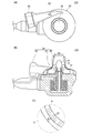
- FIG. 2 is a diagram for explaining the auxiliary artificial heart pump 110 according to the embodiment.
- 2A is a top view of the auxiliary artificial heart pump 110
- FIG. 2B is a cross-sectional view of the auxiliary artificial heart pump 110
- FIG. 2C is indicated by reference numeral A in FIG. 2B. It is a figure which expands and shows a part.
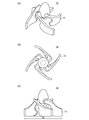
- Drawing 3 is a figure shown in order to explain rotation part 10 in an embodiment.
- FIG. 3A is a perspective view of the rotating unit 10
- FIG. 3B is a top view of the rotating unit 10
- FIG. 3C is a front view of the rotating unit 10.
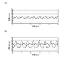
- FIG. 4 is a graph shown for explaining the state of blood flow measured using the auxiliary artificial heart pump 110 and the liquid discharge source according to the embodiment.
- FIG. 4A is a graph showing a state of blood flow in a state where the auxiliary artificial heart pump 110 is not connected to a device that simulates a failing heart (pulsation simulator), and FIG. It is a graph which shows the mode of the blood flow in the state which connected the heart pump.
- the vertical axis in FIG. 4 represents the flow rate (L / min), and the horizontal axis represents time (sec).
- the solid line indicates the liquid flow rate (total flow) when the whole including the liquid discharge source, the auxiliary artificial heart pump, and the like is shown, and the dashed line indicates the auxiliary artificial heart pump. This is the flow rate (pump flow).
- FIG. 5 is a graph shown for explaining the relationship between the head and flow rate of the auxiliary artificial heart pump 110 according to the embodiment.
- the upper graph is a graph in which the flow rate is 5 L / min when the lift is 100 mmHg
- the lower graph is a graph in which the deadline lift is 80 mmHg.
- a broken line in contact with the upper graph is a tangent at a point where the head is 100 mmHg and the flow rate is 5 L / min.
- the auxiliary artificial heart pump 110 constitutes a part of the auxiliary artificial heart system 100 as shown in FIG.
- the auxiliary artificial heart system 100 includes artificial blood vessels 120 and 130, a cable 140, and a control unit 150 (not shown).
- the control unit 150 is connected to the auxiliary artificial heart pump 110 via the cable 140 and controls the operation of the auxiliary artificial heart pump 110.
- the auxiliary artificial heart pump 110 is a centrifugal auxiliary artificial heart pump including a rotating unit 10 (see FIG. 3) having an impeller 12 and a housing 20 that houses the rotating unit 10.
- the auxiliary artificial heart pump 110 is an implantable auxiliary artificial heart pump that is used by being implanted in a human body during actual use.
- the auxiliary artificial heart pump 110 includes a drive unit that rotationally drives the rotating unit 10 and a cool seal that performs functions such as lubrication, cooling, and maintenance of sealing performance inside the auxiliary artificial heart pump 110.
- a flow path of a liquid also referred to as a purge liquid, for example, water or physiological saline
- a purge liquid for example, water or physiological saline
- the housing 20 includes a storage unit 22 that stores a rotating unit, a blood introduction unit 30 that introduces blood from outside the auxiliary artificial heart pump 110 into the auxiliary artificial heart pump 110, and an auxiliary artificial heart pump 110 from inside the auxiliary artificial heart pump 110.
- the blood introduction part and the blood delivery part may be provided separately from the housing.
- the auxiliary artificial heart pump 110 has a large fluctuation in flow rate relative to the fluctuation in the head when a liquid (blood when used in the body) is flowed with the rotation speed of the rotating unit 10 being constant.
- the graph of FIG. 4 shows a pulsation simulator (pulsation simulator) that actually manufactures an auxiliary artificial heart pump having the same configuration as the auxiliary artificial heart pump 110 according to the embodiment, and simulates the delivery of blood from the heart.
- the experiment was performed by connecting an auxiliary artificial heart pump, and the results were obtained in a graph.
- As the working liquid for the test an aqueous glycerin solution having a viscosity of 3.5 cP was used.
- the graph result (waveform) reflects disturbance factors such as a pressure spike waveform due to opening and closing of the valve.
- the maximum flow rate of liquid (average maximum flow rate is 8.25 L / min) and the minimum flow rate (average minimum flow rate is 4 when the auxiliary artificial heart pump 110 is connected to the liquid discharge source. .91 L / min) is 3.34 L / min.
- the difference between the maximum flow rate and the minimum flow rate in the state where the auxiliary artificial heart pump 110 is connected to the liquid discharge source that discharges the liquid while increasing or decreasing the flow rate at a constant cycle is the liquid flow rate. It is 40% or more of the difference between the maximum flow rate and the minimum flow rate of the liquid when the auxiliary artificial heart pump 110 is not connected to the discharge source, more specifically 80% or more, and specifically about 87%.
- the maximum pump flow rate (average maximum flow rate is 11.73 L / min) and the minimum flow rate (average minimum flow rate is 1.38 L / min) is 10.35 L / min. Therefore, in the auxiliary artificial heart pump 110, the difference between the maximum flow rate and the minimum flow rate of the pump flow rate in a state where the auxiliary artificial heart pump 110 is connected to a liquid discharge source that discharges liquid while increasing or decreasing the flow rate at a constant cycle, It is 200% or more of the difference between the maximum flow rate and the minimum flow rate when the auxiliary artificial heart pump 110 is not connected to the liquid discharge source, more specifically 250% or more, specifically about 270%.
- the difference between the maximum flow rate and the minimum flow rate of the pump flow rate when the auxiliary artificial heart pump is connected to the liquid discharge source is connected to the liquid discharge source. Since it is 200% or more of the difference between the maximum flow rate and the minimum flow rate of the liquid in the non-operating state, the fluctuation in the flow rate becomes sufficiently large with respect to the fluctuation in the head. As a result, it is possible to suppress the degree of deterioration of the user's health condition when used for a long period of time as compared with the conventional auxiliary artificial heart pump.
- the graph of FIG. 5 is a graph based on the results of manufacturing an auxiliary artificial heart pump having the same configuration as the auxiliary artificial heart pump 110 according to the embodiment, performing an experiment using the auxiliary artificial heart pump. It was obtained by doing.
- As the working liquid for the test an aqueous glycerin solution having a viscosity of 3.5 cP was used.
- the auxiliary artificial heart pump 110 measures the relationship between the head and the flow rate using a liquid whose viscosity and density are equivalent to blood as the working liquid, and takes the head in the unit of mmHg at a fixed rotation speed.
- the flow rate is 5 L / min or more, more specifically 10 L / min or more at a point where the 20 mmHg pressure is low from the deadline.
- the auxiliary artificial heart pump 110 measures the relationship between the head and the flow rate using a liquid whose viscosity and density are equivalent to blood as an operating liquid, and the head is expressed in mmHg at a constant rotational speed.
- the slope of the graph at the point where the head is 100 mmHg and the flow rate is 5 L / min is within the range of -5 to 0. In other words, it is in the range of -3 to 0, specifically about -2.4.
- the rotating unit 10 is directly connected to the driving unit through a rotating shaft.
- the bearing portion of the rotating unit 10 is a mechanical seal, and has a structure that prevents blood from entering.
- the minimum distance between the impeller 12 and the inner wall of the housing 20 during operation of the auxiliary artificial heart pump 110 is in the range of 0.1 mm to 2.0 mm, and more specifically 0.5 mm to 0. .8 mm, for example, 0.6 mm. (See d1 in FIG. 2C.)
- the pressure loss when the pressure loss is measured at a flow rate of 6 L / min in a state where the auxiliary artificial heart pump 110 is stopped with a liquid whose viscosity and density are equivalent to blood as an operating liquid, the pressure loss Is 20 mmHg or less, more specifically in the range of 5 mmHg to 16 mmHg, for example, 14 mmHg.
- the value obtained by dividing the volume of the rotating part 10 by the internal volume of the housing 20 is in the range of 0.01 to 0.50, and more specifically in the range of 0.06 to 0.12. For example, 0.09.
- the rotation diameter of the impeller 12 (see d2 in FIG. 3C) is 40 mm, and the minimum inner diameter of the blood introduction part 30 (see d3 in FIG. 2B) is 16 mm. Therefore, the numerical value obtained by dividing the minimum inner diameter of the blood introduction part in the auxiliary artificial heart pump by the rotation diameter of the impeller 12 is in the range of 0.2 to 0.8, specifically 0.4. It is to be noted that the inner diameter of the blood introduction portion 30 is the smallest at the connection portion with the artificial blood vessel 120 (see the tip of the blood introduction portion 30, see FIG. 2B), and the minimum inner diameter is the diameter of the portion. .
- the minimum inner diameter of blood delivery unit 40 (see d4 in FIG. 2B) is 10 mm.
- the numerical value obtained by dividing the minimum inner diameter of the blood delivery part in the auxiliary artificial heart pump 110 by the rotational diameter of the impeller 12 is in the range of 0.2 to 0.8. 0.25. It is to be noted that the inner diameter of the blood delivery part 40 is minimized in the vicinity of the junction between the blood delivery part 40 and the storage part 22 (in the back of the blood introduction part 40, see FIG. 2B). The diameter of the part.
- the difference between the maximum flow rate and the minimum flow rate of the liquid in a state where the auxiliary artificial heart pump 110 is connected to the liquid discharge source is connected to the liquid discharge source. Since it is 40% or more of the difference between the maximum flow rate and the minimum flow rate of the liquid in the non-operating state, the flow rate variation is sufficiently large with respect to the lift variation. As a result, it is possible to suppress the degree of deterioration of the user's health condition when used for a long period of time as compared with the conventional auxiliary artificial heart pump.
- the flow rate is 5 L / min or more at a point where the pressure of 20 mmHg is lower than the deadline lifting height, so that the height of the lifting head is larger than that of the conventional auxiliary artificial heart pump.
- the flow rate becomes sufficiently large, and the pulsatility of blood flow generated by the pulsation of the heart can be fully utilized. As a result, it is possible to suppress the degree of deterioration of the user's health condition when used for a long period of time as compared with the conventional auxiliary artificial heart pump.
- the slope of the graph at the point where the head is 100 mmHg and the flow rate is 5 L / min is in the range of ⁇ 5 to 0.
- the fluctuation of the flow rate is sufficiently larger than the fluctuation of the head as compared with the heart pump, and the pulsatility of blood generated by the pulsation of the heart can be fully utilized.
- the flow rate fluctuation is large with respect to the lift fluctuation (that is, the pressure fluctuation caused by the heart beat), so that the blood flow produced by the heart beat is reduced.
- the pulsatility can be fully utilized. As a result, it is possible to suppress the degree of deterioration of the user's health condition when used for a long period of time as compared with the conventional auxiliary artificial heart pump.
- auxiliary artificial heart pump 110 a liquid whose viscosity and density are equivalent to blood is used as an operating liquid, and the flow rate is 6 L / min in a state where the auxiliary artificial heart pump 110 is stopped. Since the pressure loss is 20 mmHg or less, it is possible to sufficiently reduce the pressure loss and fully utilize the pulsatility of the blood flow.
- the numerical value obtained by dividing the volume of the rotating unit 10 by the internal volume of the housing 20 is in the range of 0.01 to 0.50, so that the pressure loss is sufficiently reduced. It is possible to sufficiently reduce the pulsatility of the blood flow and to ensure a sufficient force for the rotating part to move the blood.
- the minimum distance between the impeller 12 and the inner wall of the housing 20 during the operation of the auxiliary artificial heart pump 110 is in the range of 0.1 mm to 2.0 mm. It is possible to sufficiently reduce the pressure loss to fully utilize the pulsation of the blood flow, and to sufficiently secure the force for pumping blood with the impeller.
- the auxiliary artificial heart pump 110 is a centrifugal auxiliary artificial heart pump, and the minimum inner diameter of the blood introduction part 30 in the auxiliary artificial heart pump 110 is set to the rotational diameter of the impeller 12. Since the value divided by 0.2 is within the range of 0.2 to 0.8, it is possible to sufficiently use the pulsatility of the blood flow by sufficiently reducing the pressure loss and sufficiently compact auxiliary An artificial heart pump can be obtained.
- the numerical value obtained by dividing the minimum inner diameter of the blood delivery unit 40 in the auxiliary artificial heart pump 110 by the rotation diameter of the impeller 12 is in the range of 0.2 to 0.8. For this reason, it is possible to sufficiently reduce the pressure loss and fully utilize the pulsatility of the blood flow, and to obtain a sufficiently compact auxiliary artificial heart pump.
- the auxiliary artificial heart pump 110 is “the maximum flow rate and the minimum flow rate of the liquid in the state where the auxiliary artificial heart pump 110 is connected to the liquid discharge source that discharges the liquid while increasing / decreasing the flow rate at a constant cycle.
- the difference between the maximum flow rate and the minimum flow rate when the auxiliary artificial heart pump 110 is not connected to the liquid discharge source is 40% or more.
Landscapes
- Health & Medical Sciences (AREA)
- Heart & Thoracic Surgery (AREA)
- Engineering & Computer Science (AREA)
- Cardiology (AREA)
- Mechanical Engineering (AREA)
- Anesthesiology (AREA)
- Biomedical Technology (AREA)
- Hematology (AREA)
- Life Sciences & Earth Sciences (AREA)
- Animal Behavior & Ethology (AREA)
- General Health & Medical Sciences (AREA)
- Public Health (AREA)
- Veterinary Medicine (AREA)
- External Artificial Organs (AREA)
- Structures Of Non-Positive Displacement Pumps (AREA)
Priority Applications (4)
| Application Number | Priority Date | Filing Date | Title |
|---|---|---|---|
| JP2014507103A JP6345112B2 (ja) | 2012-03-27 | 2012-03-27 | 補助人工心臓ポンプ |
| PCT/JP2012/057999 WO2013145134A1 (fr) | 2012-03-27 | 2012-03-27 | Pompe pour dispositif d'assistance ventriculaire |
| US14/388,264 US9440012B2 (en) | 2012-03-27 | 2012-03-27 | Ventricular assist blood pump |
| CN201280058759.4A CN103957958B (zh) | 2012-03-27 | 2012-03-27 | 辅助人工心脏泵 |
Applications Claiming Priority (1)
| Application Number | Priority Date | Filing Date | Title |
|---|---|---|---|
| PCT/JP2012/057999 WO2013145134A1 (fr) | 2012-03-27 | 2012-03-27 | Pompe pour dispositif d'assistance ventriculaire |
Publications (1)
| Publication Number | Publication Date |
|---|---|
| WO2013145134A1 true WO2013145134A1 (fr) | 2013-10-03 |
Family
ID=49258501
Family Applications (1)
| Application Number | Title | Priority Date | Filing Date |
|---|---|---|---|
| PCT/JP2012/057999 Ceased WO2013145134A1 (fr) | 2012-03-27 | 2012-03-27 | Pompe pour dispositif d'assistance ventriculaire |
Country Status (4)
| Country | Link |
|---|---|
| US (1) | US9440012B2 (fr) |
| JP (1) | JP6345112B2 (fr) |
| CN (1) | CN103957958B (fr) |
| WO (1) | WO2013145134A1 (fr) |
Cited By (3)
| Publication number | Priority date | Publication date | Assignee | Title |
|---|---|---|---|---|
| WO2019064571A1 (fr) * | 2017-09-29 | 2019-04-04 | 株式会社サンメディカル技術研究所 | Pompe de dispositif d'assistance ventriculaire |
| JP2019098007A (ja) * | 2017-12-06 | 2019-06-24 | 株式会社サンメディカル技術研究所 | 補助人工心臓システム及び血液ポンプ用コントローラ |
| JP2020537726A (ja) * | 2017-08-23 | 2020-12-24 | 杭州三花研究院有限公司Hangzhou Sanhua Research Institute Co.,Ltd. | 電動ポンプ |
Families Citing this family (21)
| Publication number | Priority date | Publication date | Assignee | Title |
|---|---|---|---|---|
| EP3088016A1 (fr) * | 2015-04-29 | 2016-11-02 | Berlin Heart GmbH | Dispositif de pompe et procédé de fonctionnement d'une pompe pour liquides |
| WO2017136718A1 (fr) * | 2016-02-04 | 2017-08-10 | Heartware, Inc. | Indice de travail de capacité de pompe |
| CN109982738B (zh) * | 2016-11-21 | 2021-06-22 | 心脏起搏器股份公司 | 递送设备和壁贴附感测 |
| CN110944689B (zh) | 2017-06-07 | 2022-12-09 | 施菲姆德控股有限责任公司 | 血管内流体运动设备、系统和使用方法 |
| CN107505455A (zh) * | 2017-09-27 | 2017-12-22 | 深圳核心医疗器械有限公司 | 一种心室辅助装置溶血实验的简易测试装置与测试方法 |
| WO2019094963A1 (fr) | 2017-11-13 | 2019-05-16 | Shifamed Holdings, Llc | Dispositifs de déplacement de liquide intravasculaire, systèmes et procédés d'utilisation |
| WO2019152875A1 (fr) | 2018-02-01 | 2019-08-08 | Shifamed Holdings, Llc | Pompes à sang intravasculaires et méthodes d'utilisation et procédés de fabrication |
| US12161857B2 (en) | 2018-07-31 | 2024-12-10 | Shifamed Holdings, Llc | Intravascular blood pumps and methods of use |
| WO2020073047A1 (fr) | 2018-10-05 | 2020-04-09 | Shifamed Holdings, Llc | Pompes à sang intravasculaires et procédés d'utilisation |
| US11964145B2 (en) | 2019-07-12 | 2024-04-23 | Shifamed Holdings, Llc | Intravascular blood pumps and methods of manufacture and use |
| WO2021016372A1 (fr) | 2019-07-22 | 2021-01-28 | Shifamed Holdings, Llc | Pompes à sang intravasculaires à entretoises et procédés d'utilisation et de fabrication |
| EP4010046B1 (fr) | 2019-08-07 | 2026-07-15 | Supira Medical, Inc. | Pompes sanguines à cathéter et boîtiers de pompe pliants |
| WO2021062270A1 (fr) | 2019-09-25 | 2021-04-01 | Shifamed Holdings, Llc | Pompes à sang de cathéter et boîtiers de pompe pliables |
| EP4034192B1 (fr) | 2019-09-25 | 2025-12-24 | Supira Medical, Inc. | Dispositifs et systèmes de pompes à sang intravasculaires et leurs procédés d'utilisation et de commande |
| EP4782050A1 (fr) | 2019-09-25 | 2026-07-29 | Supira Medical, Inc. | Pompes à sang à cathéter et conduits de sang pliables |
| EP4072650A4 (fr) | 2019-12-11 | 2024-01-10 | Shifamed Holdings, LLC | Pompes à sang d'aorte descendante et de veine cave |
| WO2021127503A1 (fr) | 2019-12-19 | 2021-06-24 | Shifamed Holdings, Llc | Pompes à sang intravasculaires, moteurs et commande de fluide |
| EP4366817A1 (fr) | 2021-07-07 | 2024-05-15 | FBR Medical, Inc. | Impulseur partiellement déformable et pompe d'assistance circulatoire pour cathéter incorporant cet impulseur |
| CN114344702B (zh) * | 2021-11-29 | 2022-12-06 | 苏州心擎医疗技术有限公司 | 导管泵及泵体 |
| WO2024137187A1 (fr) * | 2022-12-19 | 2024-06-27 | Fbr Medical, Inc. | Impulseur pour pompes à sang, cages et ensembles associés |
| USD1136184S1 (en) | 2023-04-28 | 2026-07-21 | Fbr Medical, Inc. | Micro impeller for a catheter blood pump |
Citations (2)
| Publication number | Priority date | Publication date | Assignee | Title |
|---|---|---|---|---|
| JP2005058617A (ja) * | 2003-08-19 | 2005-03-10 | Miwatec:Kk | 血流ポンプ。 |
| JP2009297174A (ja) * | 2008-06-11 | 2009-12-24 | San Medical Gijutsu Kenkyusho:Kk | 人工心臓制御装置、人工心臓システム及び人工心臓の制御方法 |
Family Cites Families (12)
| Publication number | Priority date | Publication date | Assignee | Title |
|---|---|---|---|---|
| AUPO902797A0 (en) * | 1997-09-05 | 1997-10-02 | Cortronix Pty Ltd | A rotary blood pump with hydrodynamically suspended impeller |
| DE69842053D1 (de) | 1997-12-27 | 2011-01-27 | Jms Co Ltd | Blutzirkulationshilfsvorrichtung mit einer kontinuierlichen blutflusspumpe |
| CA2374989A1 (fr) | 2002-03-08 | 2003-09-08 | Andre Garon | Dispositif d'assistance ventriculaire comprenant une pompe a sang hybride a double entree |
| US7416525B2 (en) | 2003-09-18 | 2008-08-26 | Myrakelle, Llc | Rotary blood pump |
| US7591777B2 (en) | 2004-05-25 | 2009-09-22 | Heartware Inc. | Sensorless flow estimation for implanted ventricle assist device |
| US20070142923A1 (en) | 2005-11-04 | 2007-06-21 | Ayre Peter J | Control systems for rotary blood pumps |
| WO2007084339A2 (fr) | 2006-01-13 | 2007-07-26 | Heartware, Inc. | Pompe sanguine rotative |
| AU2007201127B2 (en) | 2006-03-23 | 2012-02-09 | Thoratec Corporation | System For Preventing Diastolic Heart Failure |
| US20070282298A1 (en) | 2006-04-20 | 2007-12-06 | Ventrassist Pty Ltd | System and method for controlling a rotary blood pump |
| US8226712B1 (en) | 2008-06-13 | 2012-07-24 | Newheart Medical Devices Llc | Total artificial heart system for auto-regulating flow and pressure |
| WO2011047160A2 (fr) | 2009-10-16 | 2011-04-21 | University Of Rochester | Dispositif de transfert d'énergie magnétique transcutané |
| JP5818897B2 (ja) | 2010-09-24 | 2015-11-18 | ソーラテック コーポレイション | 人為的拍動の発生 |
-
2012
- 2012-03-27 US US14/388,264 patent/US9440012B2/en active Active
- 2012-03-27 WO PCT/JP2012/057999 patent/WO2013145134A1/fr not_active Ceased
- 2012-03-27 CN CN201280058759.4A patent/CN103957958B/zh active Active
- 2012-03-27 JP JP2014507103A patent/JP6345112B2/ja active Active
Patent Citations (2)
| Publication number | Priority date | Publication date | Assignee | Title |
|---|---|---|---|---|
| JP2005058617A (ja) * | 2003-08-19 | 2005-03-10 | Miwatec:Kk | 血流ポンプ。 |
| JP2009297174A (ja) * | 2008-06-11 | 2009-12-24 | San Medical Gijutsu Kenkyusho:Kk | 人工心臓制御装置、人工心臓システム及び人工心臓の制御方法 |
Non-Patent Citations (1)
| Title |
|---|
| UEKOMI-GATA HOJO JINKO SHINZO EVAHEART, November 2011 (2011-11-01) * |
Cited By (6)
| Publication number | Priority date | Publication date | Assignee | Title |
|---|---|---|---|---|
| JP2020537726A (ja) * | 2017-08-23 | 2020-12-24 | 杭州三花研究院有限公司Hangzhou Sanhua Research Institute Co.,Ltd. | 電動ポンプ |
| JP7476095B2 (ja) | 2017-08-23 | 2024-04-30 | 浙江三花智能控制股▲ふん▼有限公司 | 電動ポンプ |
| WO2019064571A1 (fr) * | 2017-09-29 | 2019-04-04 | 株式会社サンメディカル技術研究所 | Pompe de dispositif d'assistance ventriculaire |
| CN111163814A (zh) * | 2017-09-29 | 2020-05-15 | 株式会社太阳医疗技术研究所 | 辅助人工心脏泵 |
| JPWO2019064571A1 (ja) * | 2017-09-29 | 2020-09-03 | 株式会社サンメディカル技術研究所 | 補助人工心臓ポンプ |
| JP2019098007A (ja) * | 2017-12-06 | 2019-06-24 | 株式会社サンメディカル技術研究所 | 補助人工心臓システム及び血液ポンプ用コントローラ |
Also Published As
| Publication number | Publication date |
|---|---|
| CN103957958A (zh) | 2014-07-30 |
| JPWO2013145134A1 (ja) | 2015-08-03 |
| JP6345112B2 (ja) | 2018-06-20 |
| CN103957958B (zh) | 2016-06-01 |
| US20150297812A1 (en) | 2015-10-22 |
| US9440012B2 (en) | 2016-09-13 |
Similar Documents
| Publication | Publication Date | Title |
|---|---|---|
| JP6345112B2 (ja) | 補助人工心臓ポンプ | |
| JP6345113B2 (ja) | 補助人工心臓システム | |
| JP6329358B2 (ja) | 経弁導管用支持ステント | |
| US20210154464A1 (en) | Heart failure recovery device and method of treatment | |
| WO2023226779A1 (fr) | Pompe cardiaque à intervention par cathéter | |
| Reul et al. | Blood pumps for circulatory support | |
| JP4179634B2 (ja) | 心内血液ポンプ | |
| US8226712B1 (en) | Total artificial heart system for auto-regulating flow and pressure | |
| JP6927480B2 (ja) | カテーテル・シミュレーター用拍動流生成ポンプ | |
| CN115192895A (zh) | 医疗器械 | |
| JP2013523310A (ja) | ポリマー弁及びこれを用いた拍動型導管型心室補助装置 | |
| JP2011515174A (ja) | 心臓補助装置 | |
| CN107080871A (zh) | 导管鞘和心室辅助循环装置 | |
| CA2374989A1 (fr) | Dispositif d'assistance ventriculaire comprenant une pompe a sang hybride a double entree | |
| TW201517890A (zh) | 眼科潤滑系統及相關設備、系統及方法 | |
| JP2016508841A (ja) | 医療機器用安全装置ポンプに関する方法、システム及び装置 | |
| CN107091740B (zh) | 血泵寿命测试装置 | |
| CN111097077B (zh) | 一种体外磁驱动液悬浮轴流式血泵 | |
| Bertram | Measurement for implantable rotary blood pumps | |
| CN102284091A (zh) | 一种左心辅助装置 | |
| Slaughter et al. | Transapical miniaturized ventricular assist device: design and initial testing | |
| US10874779B2 (en) | Artificial heart and its drive unit | |
| WO2019024111A1 (fr) | Dispositif de simulation cardiaque | |
| CN116077821A (zh) | 一种压力驱动式心脏辅助装置 | |
| US20200230306A1 (en) | Ventricular assist blood pump |
Legal Events
| Date | Code | Title | Description |
|---|---|---|---|
| 121 | Ep: the epo has been informed by wipo that ep was designated in this application |
Ref document number: 12872440 Country of ref document: EP Kind code of ref document: A1 |
|
| ENP | Entry into the national phase |
Ref document number: 2014507103 Country of ref document: JP Kind code of ref document: A |
|
| WWE | Wipo information: entry into national phase |
Ref document number: 14388264 Country of ref document: US |
|
| NENP | Non-entry into the national phase |
Ref country code: DE |
|
| 122 | Ep: pct application non-entry in european phase |
Ref document number: 12872440 Country of ref document: EP Kind code of ref document: A1 |