WO2013145199A1 - Procédé d'ordonnancement d'ordinateurs virtuels - Google Patents
Procédé d'ordonnancement d'ordinateurs virtuels Download PDFInfo
- Publication number
- WO2013145199A1 WO2013145199A1 PCT/JP2012/058295 JP2012058295W WO2013145199A1 WO 2013145199 A1 WO2013145199 A1 WO 2013145199A1 JP 2012058295 W JP2012058295 W JP 2012058295W WO 2013145199 A1 WO2013145199 A1 WO 2013145199A1
- Authority
- WO
- WIPO (PCT)
- Prior art keywords
- priority
- virtual machine
- schedule
- identifier
- interrupt
- Prior art date
- Legal status (The legal status is an assumption and is not a legal conclusion. Google has not performed a legal analysis and makes no representation as to the accuracy of the status listed.)
- Ceased
Links
Images





Classifications
-
- G—PHYSICS
- G06—COMPUTING OR CALCULATING; COUNTING
- G06F—ELECTRIC DIGITAL DATA PROCESSING
- G06F9/00—Arrangements for program control, e.g. control units
- G06F9/06—Arrangements for program control, e.g. control units using stored programs, i.e. using an internal store of processing equipment to receive or retain programs
- G06F9/46—Multiprogramming arrangements
- G06F9/48—Program initiating; Program switching, e.g. by interrupt
- G06F9/4806—Task transfer initiation or dispatching
- G06F9/4843—Task transfer initiation or dispatching by program, e.g. task dispatcher, supervisor, operating system
- G06F9/4881—Scheduling strategies for dispatcher, e.g. round robin, multi-level priority queues
- G06F9/4887—Scheduling strategies for dispatcher, e.g. round robin, multi-level priority queues involving deadlines, e.g. rate based, periodic
Definitions
- the present invention relates to a computer system operated by a virtual computer that requires real-time performance in a server virtualization environment, and more particularly, is a method for scheduling a virtual computer on a computer with a limited CPU resource.
- Server virtualization technology can reduce operating costs, computer installation location, power consumption, etc. by reducing the number of physical computers by executing multiple virtual machines (VMs) on one physical computer
- VMs virtual machines
- real-time performance is required by the application in the virtual machine.
- a performance guarantee method such as occupying the CPU resource.
- sufficient real-time performance Guarantees are difficult.
- interruptions frequently occur from an external device such as a network device connected to a computer
- a processing delay of an application in the virtual computer occurs, further aggravating the situation.
- the control system requires real-time guarantee of the application on the virtual machine even in such a computer situation.
- the application to be processed by the virtual machine is divided into units of threads, and the divided thread units are shared by a plurality of virtual machines to perform processing.
- the execution order of virtual machines was scheduled.
- the load (and processing capability) of each CPU is different, it is difficult to cope with a multi-CPU environment having a plurality of CPU configurations, so that the CPU resources of the physical computer cannot be effectively used.
- the present invention provides a real-time property of an application processed by a virtual computer in a scheduling method of a virtual system composed of a plurality of virtual computers operating a large-scale application in a physical computer environment where one or more CPU resources can be used. It is an object of the present invention to provide a virtual machine scheduling technique that can guarantee the above.
- the physical computer and each virtual computer share a physical NIC, and communicate with external devices such as a computer server and a controller via the physical NIC.
- a VM scheduler control unit is provided on the host OS inside the computer.
- a guest OS runs on each virtual machine and executes an application on the virtual machine.
- an in-VM schedule control unit that determines the execution order of the applications in the group according to the execution priority of the application is provided.
- the host OS is provided with a virtualization program having a scheduling function for allocating CPU resources to each virtual machine and an interrupt processing function for transmitting an interrupt from an external device to the virtual machine.
- the guest OS processes a schedule function that can execute an application by allocating a CPU resource allocated from the host OS to each virtual machine to an application in the virtual machine, and an interrupt notified from a virtualization program on the host OS. It is assumed that it has a function.
- the in-VM schedule control unit operating on the guest OS divides the applications in the virtual machine into groups according to priority.
- the first application and the last application to be executed in the group prepared by the in-VM schedule control unit are registered at the beginning and the end of each group.
- Each priority group has an identifier representing the priority.
- “L1” is the highest priority group and “Ln” is the lowest priority group.
- the in-VM schedule control unit manages the processing time of each priority group so as to ensure that all applications belonging to any group from “L1” to “Ln” are processed on a certain deadline.
- the processing time of each group is managed by the start time of the group head application and the end time of the last application. The deadline design needs to be adjusted according to the requirements of the system providing the present invention.
- the in-VM schedule control unit of each guest OS includes a notification means with the VM scheduler control unit on the host OS.
- the VM schedule control unit on the guest OS performs the start of the first application and the last application of the priority group in the virtual machine. The end is notified to the VM scheduler control unit on the host OS.
- the above notification is not performed. Since the overhead of notification from the virtual machine to the host OS is large, the overhead is reduced by not managing the start / end of the low priority group.
- the VM scheduler control unit on the host OS can grasp the priority of the application executed in each virtual machine.
- the VM scheduler control unit on the host OS always records and manages the priority group priority as the execution state of each virtual machine, and lowers the priority of the notification source virtual machine with a high priority group end notification. Go. Therefore, it is possible to grasp the virtual machine to which the CPU resource should be assigned with the highest priority among the plurality of virtual machines.
- a group having a low priority such as “Ln” is not schedule control based on deadline based on notification of the start of the first application and the end of the last application from the in-VM schedule control unit in the virtual machine to the host OS. Schedule control is performed at the quota time for allocating CPU resources to be executed.
- an interrupt management control unit is provided in the VM scheduler control unit on the host OS to limit the number of interrupts allowed in the deadline of the virtual machine.
- the interrupt number limit manages the number obtained by dividing one interrupt processing time with respect to the allowable value of the deadline of each virtual machine as the limit value of the interrupt number. If the interrupt number from the virtualization program on the host OS is within the interrupt limit value, the virtual machine is notified of the interrupt.
- the priority is changed to the highest priority regardless of the current execution priority of the corresponding virtual machine, and the host OS allocates CPU resources to the corresponding virtual machine.
- interrupt processing is performed by the guest OS, and the scheduler of the guest OS selects an application of the priority group set by the VM internal schedule control unit, and allocates CPU resources.
- a quota time for maintaining the priority is set in the highest priority setting based on the interrupt notification. That is, when the time allocated for interrupt processing reaches the quota time, the priority is adjusted to the original priority, and the host OS always allocates CPU resources to the virtual machine with the highest priority.
- the CPU resources according to the priority group executed in the virtual machine by the application management method in the priority group by the VM schedule control unit in the virtual machine and the VM scheduler control unit on the host OS By allocating to the virtual machine, it is possible to guarantee the real-time property of the application in the virtual machine even in a system with limited CPU resources.
- by providing an interrupt management control unit in the VM scheduler control unit on the host OS it is possible to guarantee real-time applications in the virtual computer even in a computer environment with a high load of interrupt processing.
- the VM scheduler control unit manages the CPU resource allocation of the virtual machine by the deadline of the priority group of the processing application in the virtual machine, the real-time guarantee can be ensured even in the computer system in which the CPU resource is limited. It becomes possible.
- the number of interrupt notifications and processes is limited by the deadline of the priority group of the processing application in the virtual machine, so real-time performance is guaranteed. It becomes possible.
- FIG. 1 is an overall configuration diagram of virtual machine schedule control according to the embodiment of this invention.
- the virtual machine schedule control includes one virtualization system 1, one terminal 2, and an external network 3.
- the virtualization system 1 is composed of one computer.
- the computer 100 includes a memory 101, a processor 102, a storage device 103, and an external communication interface 104.
- a host operating system 400 abbreviated as “host OS” in the figure
- a VM scheduler control program 300 abbreviated as “VM” in the figure
- a virtualization program 401 is held in the host OS 400.
- the VM scheduler control program 300 includes an in-VM schedule management table 301, a VM management table 302, a timer-management table 303, an interrupt management table 304, an in-VM schedule input program 305, a VM dead run management program 306, a timer-management program 307, and It consists of an interrupt management program 308.
- the VM 200 includes an application 211 (abbreviated as AP in the figure), a schedule 212 in the VM, a guest operating system 213 (abbreviated as guest OS in the figure), and a notification interface 214 (interface is abbreviated as I / F in the figure). Composed.
- FIG. 1 examples of VM1 (200-A) and VM2 (200-B) indicated by solid line frames as VM200 in computer 100 and other VM200 indicated by dotted line frames are shown. In particular, the number of VMs is shown. Is not limited.
- the terminal 2 and the computer 100 are connected via the external network 3.
- the external network 3 is connected to the external communication I / F 104.
- the terminal 2 can communicate with the virtualization system 1 via the external network 3.
- the storage device 103 of the computer node 100 stores a host OS 400, a VM scheduler control program 300 (programs and various table information), an AP 211, a VM schedule 212, a guest OS 213, and a notification I / F 214 that configure the VM 200.
- the processor 102 expands and executes the components of the host OS 400, the VM scheduler control program 300, and the VM 200 from the storage device 103 to the memory 101, and processes an interrupt from the external communication I / F 104.
- the external communication I / F 104 transmits / receives data to / from the terminal 2 through the external network 3.
- the virtualization program 401 is a program for creating and managing the VM 200, and notifies the VM 200 via the notification I / F 214 of an interrupt from the external communication I / F 104.
- the host OS 400 uses the virtualization program 401 to control the execution of the VM scheduler control program 300 and the VM 200 and to control access to the external communication I / F 104 and the storage device 103.
- the VM 200 is a virtual execution environment created by the virtualization program 401 in which a unique program or operating system can operate.
- programs and operating systems that operate in different VMs 200 may be the same or different.
- programs and operating systems operating in different VMs 200 do not directly affect each other.
- the VM 200 has a unique identifier in the virtualization system 1. For example, the VM 200 in FIG. 1 has an identifier of “VM1” or “VM2”.
- AP 211 is an operation application program in the VM 200.
- AP1-1 (211-A) and AP1-n (211-B) are shown as APs 211, but the number of APs 211 operating in the VM 200 is not limited.
- the guest OS 213 controls the AP 211 using the in-VM schedule 212 in the VM 200 environment.
- the notification IF 214 receives the processing result of the in-VM schedule 212 from the guest OS 213 and outputs it to the VM scheduler control program 300.
- the VM scheduler control program 300 When the VM scheduler control program 300 operates on the VM 200, the VM scheduler control program 300 receives the schedule information of the AP 211 in the VM 200 from the schedule 212 in the VM 200 via the notification IF 214. The VM scheduler control program 300 inputs the schedule information of the AP 211 to the in-VM schedule input program 305. The in-VM schedule input program 305 stores the schedule information of the AP 211 in the in-VM schedule management table 301.
- the in-VM schedule 212 operating in the VM 200 is grouped according to the operation priority of the AP 211 and schedules the execution time in the processor 102. A scheduling method based on operation priority will be described later.
- the in-VM schedule 212 operating in the VM 200 notifies the VM deadline management program 306 operating in the VM scheduler control program 300 via the notification IF 214 of the operation start and end of the AP 211 of the operation priority group.
- the VM deadline management program adjusts the priority of the VM 200 based on the start and end of the operation of the AP 211. Also, the operation start and end times are written in the interrupt table 304 as execution time deadlines.
- the virtualization program 401 executes the VM 200 according to the priority of the VM 200.
- the in-VM schedule 212 operating in the VM 200 notifies the timer-event management program 307 of the timer-registration of the AP 211 of the highest priority group via the notification IF 214.
- the timer-event management program 307 registers information for timer control in the timer-management table 303 and delegates timer-control to the virtualization program 401.
- the virtualization program 401 notifies the timer-event management program 307 when the timer is fired (started).
- the timer-event management program 307 notifies the interrupt management program 308 of the timer-event.
- the interrupt management program 308 notifies the VM 200 of the timer-event via the notification IF 214.
- the guest OS 213 processes the timer-event from the interrupt management program 308, and notifies the AP 211 that has performed the timer-registration of the processing result.
- the interrupt management program 308 notifies an interrupt from the external IF 104 to the VM 200 via the notification IF 214.
- the interrupt is processed by the guest OS 213.
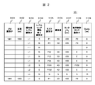
- FIG. 2 is a diagram showing a configuration of the in-VM schedule management table 301 according to the embodiment of this invention.
- the in-VM schedule management table 301 is held in the in-VM schedule 212 and the VM scheduler control program 300, and holds schedule information of the AP 211 of each VM 200 of the VM 200-A and VM 200-B created in the computer 100.
- the period 3102 stores the time when all APs 211 operating in each VM 200 are executed. In FIG. 2, it means that it takes 1 second (1000 ms) to execute from AP1-1 to AP1-n operating on VM1 of VM200-A.
- the priority level identifier 3103 stores information by which the AP 211 is grouped according to execution priority that determines the order in which the guest OS 213 executes the AP 211 and uniquely identifies the group.
- the L1 group has the highest priority, followed by L2, then L3, and then Ln.
- the AP 211 belonging to the group is configured such that the AP 211 that is executed first from the AP 211 that is executed first in the group has a ring shape (ring shape).
- the VM 200 needs to register the first and last APs 211 of each priority group in advance.
- the first and last APs 211 are APs 211 in which the in-VM schedule 213 is registered.
- the level ring start / end identifier 3104 stores “S” indicating that the first AP 211 belonging to the group starts and “E” indicating the end of the AP 211 to be executed last.
- “N” is stored in the level ring start / end identifier 3104.
- the task identifier 3105 stores information for uniquely identifying the AP 211 in the group.
- the priority 3106 stores execution priority information of the AP 211 that determines the order in which the guest OS 213 executes the AP 211.
- the runtime 3107 stores the time when the AP 211 is executed by the guest OS 213 in units of “ms”.
- the sequence control task identifier 3108 stores the task identifier 3105 of the AP 211 to be executed next when the execution of the AP 211 is completed.
- information other than the task identifier 3105 “E” is stored in the order control task identifier 3108, the corresponding AP 211 is executed.
- information “E” is stored in the task identifier 3105 and “N” is stored in the leveling start / end identifier 3104, the other AP 211 of the same group is executed.
- the time allocated to the execution of the AP 211 whose priority level identifier 3013 belongs to “Ln” is stored.
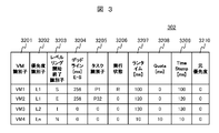
- FIG. 3 is a diagram showing a configuration of the VM management table 302 according to the embodiment of this invention.
- the VM management table 302 is used for the virtualization program 401 to execute the VM 200.
- the priority identifier 3201 information for uniquely identifying the VM 200 in the computer 100 is stored.
- the priority level identifier 3102 to which the AP 211 executed by the guest OS 213 belongs is stored.
- the priority identifier 3202 is acquired from information stored in the notification format 500 described later by the in-VM schedule 212.
- the level ring start / end identifier 3203 stores information on the start “S” of the first AP 211 or the end “E” of the last AP 211 in the priority group of the priority level identifier 3103. “I” represents a change in priority ID.
- the deadline 3204 stores the time from the start of the first AP 211 of the priority group of the priority level identifier 3103 to the end of the last AP 211 in “ms” units.
- the task identifier 3205 is acquired from information stored in the notification format 500.
- the execution state of the VM 200 executed by the virtualization program 401 is stored.
- “R” is stored in the execution state 3206.
- the VM 200 not executed by the virtualization program 401 stores “0”.
- the processor 102 has a multi-core configuration, a plurality of VMs 200 are executed by the virtualization program 401.
- the runtime 3207 stores the execution time of the VM 200 executed by the virtualization program 401 in units of “ms”.
- the time for executing the VM 200 by the virtualization program 401 is stored.
- the execution time is stored in the Quota 3208 even if the priority group has a priority other than “Ln”.
- the information of the Quota 3208 stored by the timer event management program 307 and the interrupt management program 308 is that the priority group of the AP 211 executed by the guest OS 213 after the timer-event and interrupt are processed by the guest OS 213 of the VM 200 is the priority identifier 3202. May not match.
- the VM deadline management program 306 is not notified of the start / end, so the VM 200 of the priority group whose priority identifier 3202 of the VM management table 304 is higher than “Ln”. If there is, the execution order based on priority cannot be maintained. In order to keep the execution order based on the priority, it is necessary to store the Quota 3208 in the timer-event and interrupt notification.
- Time Runtime 3207 is stored in TimeStamp 3209. This is because the VM deadline management program 307, which will be described later, determines whether the time of the Quota 3208 has elapsed.
- information on the priority identifier 3202 is stored when the priority “L1” is stored in the priority identifier 3202 in the timer-event and interrupt processing.
- the timer-event and the interrupt processing need to be preferentially processed by the VM 200 in order to guarantee the real-time property of the control system. Therefore, it is necessary to set the highest priority “L1” regardless of the execution priority of the VM 200. is there.
- the priority of the original priority 3210 is stored in the priority identifier 3202.
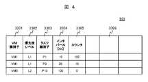
- FIG. 4 is a diagram showing a configuration of the timer-management table 303 according to the embodiment of this invention.
- the timer-management table 303 is a table necessary for the virtualization program 401 to perform timer-registration of the AP 211 belonging to the execution priority group “L1” among the APs 211 executed by the guest OS 213 of the VM 200.
- the AP 211 in the “L1” group is an application that requires real-time performance. Therefore, processing is performed not by the guest OS 213 of the VM 200 but by the virtualization program 401 of the host OS 400.
- the in-VM schedule 212 notifies the timer-event management program 307 of the timer-registration of the AP 211 belonging to the “L1” group via the notification IF 214.
- VM identifier 3301 information for uniquely identifying the VM 200 in the computer 100 is stored.
- a priority level identifier 3103 is stored in the priority level 3302.
- the task identifier 3303 stores information for identifying the AP 211.
- the interval 3304 stores the timer-event firing time.
- the counter 3305 stores the firing frequency per unit time (for example, 1 second) of the timer-event.
- FIG. 5 is a diagram showing a configuration of the interrupt management table 304 according to the embodiment of this invention.
- it is necessary to limit the number of interrupts processed by the VM 200 in order to guarantee the real-time property of the AP 211. It is managed by an interrupt management program 308 described later.
- VM identifier 3401 information for uniquely identifying the VM 200 in the computer 100 is stored.
- period 3402 information on the period 3102 of the in-VM schedule management table 301 is stored.
- the priority level 3403 stores a VM identifier 3401 managed by the timer management table 303.
- the deadline 3404 stores the deadline 3204 of the VM management table 302.
- an allowable time that can guarantee real-time performance from the execution deadline time of the AP 211 group belonging to the priority level 3404 is stored in “ms”.
- the guest OS 213 of the VM 200 stores the time for processing one interrupt from the external IF 102 in “ms”.
- the interrupt number critical value 3407 stores a value that is 90% of the number obtained by dividing one interrupt processing time 3406 with respect to the deadline allowable value 3405. By storing 90%, a margin value of 10% is provided.
- the period deadline 3408 stores the period 3102 of the in-VM schedule management table 301.
- the interrupt accumulation 3409 stores the number of interrupts generated within the period of the periodic deadline 3408.
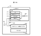
- FIG. 6A is a processing outline of the notification IF 214 according to the embodiment of this invention.
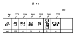
- FIG. 6B shows the configuration of the notification format 500.
- the virtualization program 401 of the host OS 400 determines the execution order of the VMs 200.
- the virtualization program 401 processes interrupts and timer-events from the external communication IF 104 and notifies the VM scheduler control program 300 of them.
- the VM scheduler control program 300 sets “L1” in the priority identifier 3202 of the VM management table 302, sets Quota 3208, and notifies the VM 200 with the notification IF 214 (501).
- the VM identifier 5001, the cycle 5002, the priority level 5003, and the task identifier 5004 at the start correspond to the respective items of the in-VM schedule management table 301 of FIG. Is set by the first AP 211 at the start of the first AP 211, and “S” is set to the start / end 5005.
- the VM scheduler control program 300 sets one interrupt processing time 5006 and an interrupt count critical value 5007 based on the items 3406 and 3407 of the interrupt management table 304 of FIG.
- a task identifier 5004 at the end is set, and “E” is set at the start / end 5005.
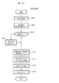
- FIG. 7 is a flowchart of the in-VM schedule 212 according to the embodiment of this invention.
- the host OS 400 and the processor 102 start the processing of the VM 200 when the VM scheduler control program 300 and the VM 200 are expanded in the memory 101 of the computer 100.
- processing of the guest OS 213 is started, and processing of the in-VM schedule 212 is started.
- the VM schedule 212 reads the VM schedule management table 301 from the storage device 103 into the memory 101 (S1001).
- the in-VM schedule 212 registers the start AP 211 and the end AP 211 for all priority level groups except the “Ln” level group stored in the information of the priority level identifier 3103 of the in-VM schedule management table 301 ( S1002).
- the AP 211 having the highest priority is selected from the task identifier 3105 from the information of the priority 3106 in the in-VM schedule management table 301 (S1003).
- the task identifier 3105 having the minimum runtime is selected from the information of the runtime 3107 in the in-VM schedule management table 301 (S1011).
- the in-VM schedule 212 registers the AP 211 having the task identifier 3105 as an application to be started by the guest OS 213 (S1021).
- the VM identifier 5001, the period 5002, the priority level 5003, and the task identifier 5004 are acquired from the in-VM schedule management table 301 and stored in the notification format 500.
- “S” is stored in the start / end 5005 (S1032).
- the start of the AP 211 is transmitted to the VM scheduler control program 300 via the notification IF 214 (S1033).
- the in-VM schedule 212 registers the AP 211 with the task identifier 3105 as an application to be processed by the guest OS 213 (S1034).
- An end process is performed (S1035) (see FIG. 8). Thereafter, the VM schedule 212 activates all APs 211 belonging to the group of the priority level identifier 3103.
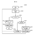
- FIG. 8 is a flowchart of the end process (1035) shown in FIG. 7 according to the embodiment of the present invention.
- the in-VM schedule 212 registers all APs 211 whose priority level identifiers 3104 in the in-VM schedule management table 301 are in the priority group as applications to be started by the guest OS 213 in the in-VM schedule 212.
- the runtime when the first AP 211 in the priority group of the priority level identifier 3104 is processed by the guest OS 213 is added to the runtime 3107 of the in-VM schedule management table 301 in FIG. 2 (S2002). It is determined from the level ring start / end identifier 3104 of the in-VM schedule management table 301 whether the AP 211 is the last AP 211 in the priority group of the priority level identifier 3104 (S2003). If the information of the start / end identifier 3104 is “E”, this is set in the notification format 500 to notify the VM scheduler control program 300 that the processing of the application in the priority group AP 211 has been completed, and the processing is performed. The process ends (S2011, S2012).
- the information of the start / end identifier 3104 is not “E”
- the runtime 3107 selects the smallest task identifier 3105 from the AP 211 in the same group, and the guest OS 213 starts the corresponding AP 211.
- the application is registered in the VM schedule 212 (S2022, S2023). Thereafter, the above process is performed for the next task.
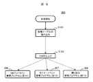
- FIG. 9 is an overall flowchart of the virtualization system 1 according to the embodiment of this invention.
- the overall processing of the virtualization system 1 includes a startup process of the VM scheduler control program 300, a VM deadline management program 306, a timer-event management program 307, and an interrupt management program 308.
- the processing of the VM scheduler control program 300 is started.
- the VM management table 301, the VM management table 302, the timer-event management table 303, and the interrupt management table 304 are read from the storage device 103 into the memory 101 (S101). ), The VM 200 is activated (S102).
- the VM scheduler control program 300 executes each of the VM deadline management program 306 (see FIG. 10), timer event management program 307 (see FIG. 12), and interrupt management program 308 (see FIG. 15). And wait for notification or interruption.
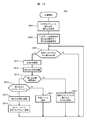
- FIG. 10 is a flowchart of the VM deadline management program 306 according to the embodiment of this invention. If there is a notification from the in-VM schedule 212 of the VM 200 (Y in S301), the start / end information 5005 of the communication format 500 from the notification IF 214 is read (S302).
- the task identifier 3205 of the VM management table 302 that matches the task identifier 5004 of the communication format 500 is searched, and the searched task identifier 3205 is searched.
- “E” is written in the leveling start / end identifier 3203 relating to (S311).
- “0” is set in the execution state 3206 to indicate that the VM 200 is not in the execution state (S312).
- the difference between the time of the host 400 and the Timestamp 3209 is stored in the deadline 3204 as a deadline.
- the deadline 3204 is added to the line time 3207 (S313).
- the level of the priority identifier 3202 of the VM 200 is lowered by 1 (S314). For example, if the level of the priority 3202 is “L1”, “L2” is stored. If the level of the priority 3202 is “Ln” (Y in S315), the time of the host OS 400 is stored in the Timestamp 3209 (S316). The leveling start / end identifier 3203 stores “I” indicating that the priority identifier 3202 is changed (S317). The host OS 400 selects the VM 200 to be processed by the processor 102 (S318) (see FIG. 11).
- the task identifier 3205 of the VM management table 302 that matches the task identifier 5004 of the communication format 500 is searched (S321). If the searched task identifier 3205 is a VM 200 not registered in the VM management table 302 (Y in S321), the searched task identifier 3205 is registered in the VM management table 302 (S331). If the retrieved task identifier 3205 is a VM 200 registered in the VM management table 302 (N in S321), the start “S” is stored in the leveling start / end identifier 3203 (S322), and the Timestamp 3209 stores the start of the host OS 400. The time is stored (S323).
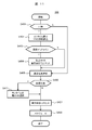
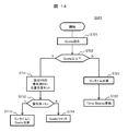
- FIG. 11 is a flowchart of execution VM selection (S318 in FIG. 10) according to the embodiment of this invention.
- the host OS 400 selects the VM 200 to be processed by the processor 102. From the VM management table 302, a VM identifier 3201 having a priority 3202 of “L1” is searched (S401). If there is no VM identifier 3201 storing the priority “L1” (Y in S401), the period 3102 of the VM identifier 3101 in the in-VM schedule management table 301 that matches the VM identifier 3201 whose runtime 3207 is the minimum is read. (S402).
- the priority identifier 3202 corresponding to the VM identifier 3201 is assigned the highest priority “L1”.
- the VM identifier 3201 having the highest priority is searched from the priority identifier 3202 (S405).
- the VM identifier 3201 having the highest priority is searched from the priority identifier 3202 (S405).
- the runtime 3207 in the same row as the VM identifier 3201 selects the smallest VM identifier 3201 (S411). “R” is stored in the execution state 3206 of the same row of the selected VM identifier 3201, indicating that it is waiting to be executed (S421).
- the selected VM identifier 3201 is registered in the host OS 400 as the VM 200 to be processed by the processor 102 by the host OS 400 (S422).
- FIG. 12 is a flowchart of the timer-event management program (307) according to the embodiment of this invention.
- Wait for timer-event notification (S501).
- the priority level 5003 of the notification format 500 is read (S503). If the priority level is “L1” (S504), the priority level is set in the timer-management table 303 and registered as a timer-event of the host OS 400 (S505).
- FIG. 13 is a flowchart of external event processing (S512 in FIG. 12, S821 in FIG. 15) according to the embodiment of this invention.
- the external event is notified from the host OS 400 to the VM scheduler control program 300.
- Information of the notification destination VM 200 is stored in the external event.
- the VM 200 that matches the VM identifier 3201 of the VM management table 302 is selected from the received external event (S601).
- the priority identifier 3202 in the column of the VM identifier 3201 is read (S602). If the priority identifier 3202 is “Ln” (Y in S603), the value “10” is stored in the Quota 3208 (S604).
- the priority identifier 3202 is stored in the original priority identifier 3210, and the highest priority “L1” is stored in the priority identifier 3202 (S611). “R” indicating waiting for execution is stored in the execution state 3206, and the host OS time is stored in the Timestamp 3209 (S612). The external event is notified to the VM scheduler control program 300 via the notification IF 214 (S613).
- the host OS 400 registers the VM identifier 3201 in the host OS 400 as the VM 200 processed by the processor 102 (S614).
- FIG. 14 is a flowchart of the quota management process (S341 in FIG. 10) according to the embodiment of this invention.
- a VM identifier 3201 other than “0” in the quota 3208 of the VM management table 302 is selected.
- the quota 3208 related to the VM identifier 3201 is read (S701).
- the original priority identifier 3210 that is, “0” is stored in the priority identifier 3202 related to the VM identifier 3201 (S711).
- the Quota 3208 is added to the runtime 3207 (S713). If the priority identifier 3202 is not “Ln” (N in S712), the Quota 3208 is added to the runtime 3207, and “0” is stored in the Quota 3208 (S714).
- the difference between the time of the host OS 400 and the Timestamp 3209 is less than the quota 3208 (N in S702)
- the difference between the time of the host OS 400 and the Timestamp 3209 is added to the runtime 3207 (S721).
- the time of the host OS 400 is stored in the Timestamp 3209 (S722).
- FIG. 15 is a flowchart of the interrupt management program (308) according to the embodiment of this invention.
- the in-VM schedule management table 301 is read, information is set in the items 3401 to 3404 of the interrupt management table 304, the default value “10” is stored in the deadline allowable value 3405, and one interrupt processing time 3406 is “ 0.1 "is stored (S801).
- the interrupt number critical value 3407 a number obtained by subtracting “10” from the number obtained by dividing one deadline allowable value 3405 by the interrupt processing time 3406 is stored (S802).
- a margin value for a critical value error caused by an error in the processing time of one interrupt processing time 3406 is set.
- interrupt accumulation 3409 is within the interrupt number critical value 3407 (Y in S813), it is determined whether or not the interrupt is a timer-event (S814). If it is a timer-event (Y in S814), “1” is subtracted from the interrupt accumulation 3409 (S815) and notified to the timer-event management program 307 (S816). If the interrupt is not a timer-event (N in S814), external event processing is called (S821) (see FIG. 13).
Landscapes
- Engineering & Computer Science (AREA)
- Software Systems (AREA)
- Theoretical Computer Science (AREA)
- Physics & Mathematics (AREA)
- General Engineering & Computer Science (AREA)
- General Physics & Mathematics (AREA)
- Stored Programmes (AREA)
- Computer And Data Communications (AREA)
- Debugging And Monitoring (AREA)
Priority Applications (4)
| Application Number | Priority Date | Filing Date | Title |
|---|---|---|---|
| ES12872541T ES2802173T3 (es) | 2012-03-29 | 2012-03-29 | Método de planificación de ordenador virtual |
| PCT/JP2012/058295 WO2013145199A1 (fr) | 2012-03-29 | 2012-03-29 | Procédé d'ordonnancement d'ordinateurs virtuels |
| EP12872541.3A EP2833264B1 (fr) | 2012-03-29 | 2012-03-29 | Procédé d'ordonnancement d'ordinateurs virtuels |
| JP2014507165A JP5820525B2 (ja) | 2012-03-29 | 2012-03-29 | 仮想計算機のスケジュールシステム及びその方法 |
Applications Claiming Priority (1)
| Application Number | Priority Date | Filing Date | Title |
|---|---|---|---|
| PCT/JP2012/058295 WO2013145199A1 (fr) | 2012-03-29 | 2012-03-29 | Procédé d'ordonnancement d'ordinateurs virtuels |
Publications (1)
| Publication Number | Publication Date |
|---|---|
| WO2013145199A1 true WO2013145199A1 (fr) | 2013-10-03 |
Family
ID=49258563
Family Applications (1)
| Application Number | Title | Priority Date | Filing Date |
|---|---|---|---|
| PCT/JP2012/058295 Ceased WO2013145199A1 (fr) | 2012-03-29 | 2012-03-29 | Procédé d'ordonnancement d'ordinateurs virtuels |
Country Status (4)
| Country | Link |
|---|---|
| EP (1) | EP2833264B1 (fr) |
| JP (1) | JP5820525B2 (fr) |
| ES (1) | ES2802173T3 (fr) |
| WO (1) | WO2013145199A1 (fr) |
Cited By (5)
| Publication number | Priority date | Publication date | Assignee | Title |
|---|---|---|---|---|
| JP6242557B1 (ja) * | 2017-03-21 | 2017-12-06 | 三菱電機株式会社 | 制御装置および制御プログラム |
| JP2019053591A (ja) * | 2017-09-15 | 2019-04-04 | 株式会社東芝 | 通知制御装置、通知制御方法及びプログラム |
| JP2022006909A (ja) * | 2020-06-25 | 2022-01-13 | Kddi株式会社 | 制御装置、情報処理装置、情報処理制御方法及びコンピュータプログラム |
| JP2022508119A (ja) * | 2019-03-11 | 2022-01-19 | エヌイーシー ラボラトリーズ アメリカ インク | ユースケース仕様およびランタイム実行 |
| US11467944B2 (en) | 2018-05-07 | 2022-10-11 | Mitsubishi Electric Corporation | Information processing apparatus, tuning method, and computer readable medium |
Families Citing this family (1)
| Publication number | Priority date | Publication date | Assignee | Title |
|---|---|---|---|---|
| CN110308991B (zh) * | 2019-06-21 | 2020-06-19 | 长沙学院 | 一种基于随机任务的数据中心节能优化方法及系统 |
Citations (2)
| Publication number | Priority date | Publication date | Assignee | Title |
|---|---|---|---|---|
| JP2005043959A (ja) * | 2003-07-22 | 2005-02-17 | Toshiba Corp | スケジューリング方法および情報処理システム |
| JP2011198027A (ja) | 2010-03-19 | 2011-10-06 | Fujitsu Ltd | 仮想マシンシステムおよび仮想マシン管理方法 |
Family Cites Families (11)
| Publication number | Priority date | Publication date | Assignee | Title |
|---|---|---|---|---|
| US7136800B1 (en) * | 2002-10-18 | 2006-11-14 | Microsoft Corporation | Allocation of processor resources in an emulated computing environment |
| US20060294238A1 (en) * | 2002-12-16 | 2006-12-28 | Naik Vijay K | Policy-based hierarchical management of shared resources in a grid environment |
| US7415708B2 (en) * | 2003-06-26 | 2008-08-19 | Intel Corporation | Virtual machine management using processor state information |
| US7765543B1 (en) * | 2003-12-17 | 2010-07-27 | Vmware, Inc. | Selective descheduling of idling guests running on a host computer system |
| US7707578B1 (en) * | 2004-12-16 | 2010-04-27 | Vmware, Inc. | Mechanism for scheduling execution of threads for fair resource allocation in a multi-threaded and/or multi-core processing system |
| US8621458B2 (en) * | 2004-12-21 | 2013-12-31 | Microsoft Corporation | Systems and methods for exposing processor topology for virtual machines |
| US8145760B2 (en) * | 2006-07-24 | 2012-03-27 | Northwestern University | Methods and systems for automatic inference and adaptation of virtualized computing environments |
| FR2937439B1 (fr) * | 2008-10-17 | 2012-04-20 | Commissariat Energie Atomique | Procede d'execution deterministe et de synchronisation d'un systeme de traitement de l'information comportant plusieurs coeurs de traitement executant des taches systemes. |
| US8019861B2 (en) * | 2009-01-29 | 2011-09-13 | Vmware, Inc. | Speculative virtual machine resource scheduling |
| US8365178B2 (en) * | 2009-10-02 | 2013-01-29 | Red Hat Israel, Ltd. | Prioritizing scheduling of virtual machines by recalculating priority numbers for each virtual machine based on the interaction of users with the virtual machines |
| US8489789B2 (en) * | 2010-02-05 | 2013-07-16 | Advanced Micro Devices, Inc. | Interrupt virtualization |
-
2012
- 2012-03-29 JP JP2014507165A patent/JP5820525B2/ja not_active Expired - Fee Related
- 2012-03-29 EP EP12872541.3A patent/EP2833264B1/fr not_active Not-in-force
- 2012-03-29 ES ES12872541T patent/ES2802173T3/es active Active
- 2012-03-29 WO PCT/JP2012/058295 patent/WO2013145199A1/fr not_active Ceased
Patent Citations (2)
| Publication number | Priority date | Publication date | Assignee | Title |
|---|---|---|---|---|
| JP2005043959A (ja) * | 2003-07-22 | 2005-02-17 | Toshiba Corp | スケジューリング方法および情報処理システム |
| JP2011198027A (ja) | 2010-03-19 | 2011-10-06 | Fujitsu Ltd | 仮想マシンシステムおよび仮想マシン管理方法 |
Cited By (10)
| Publication number | Priority date | Publication date | Assignee | Title |
|---|---|---|---|---|
| JP6242557B1 (ja) * | 2017-03-21 | 2017-12-06 | 三菱電機株式会社 | 制御装置および制御プログラム |
| WO2018173123A1 (fr) * | 2017-03-21 | 2018-09-27 | 三菱電機株式会社 | Dispositif de commande et programme de commande |
| JP2019053591A (ja) * | 2017-09-15 | 2019-04-04 | 株式会社東芝 | 通知制御装置、通知制御方法及びプログラム |
| US11188399B2 (en) | 2017-09-15 | 2021-11-30 | Kabushiki Kaisha Toshiba | Determining whether to suppress an interrupt indicating completion of processing of a frame based on priority of the frame and current value information |
| JP7000088B2 (ja) | 2017-09-15 | 2022-01-19 | 株式会社東芝 | 通知制御装置、通知制御方法及びプログラム |
| US11467944B2 (en) | 2018-05-07 | 2022-10-11 | Mitsubishi Electric Corporation | Information processing apparatus, tuning method, and computer readable medium |
| JP2022508119A (ja) * | 2019-03-11 | 2022-01-19 | エヌイーシー ラボラトリーズ アメリカ インク | ユースケース仕様およびランタイム実行 |
| JP7157877B2 (ja) | 2019-03-11 | 2022-10-20 | エヌイーシー ラボラトリーズ アメリカ インク | ユースケース仕様およびランタイム実行 |
| JP2022006909A (ja) * | 2020-06-25 | 2022-01-13 | Kddi株式会社 | 制御装置、情報処理装置、情報処理制御方法及びコンピュータプログラム |
| JP7350694B2 (ja) | 2020-06-25 | 2023-09-26 | Kddi株式会社 | 制御装置、情報処理装置、情報処理制御方法及びコンピュータプログラム |
Also Published As
| Publication number | Publication date |
|---|---|
| JP5820525B2 (ja) | 2015-11-24 |
| EP2833264A4 (fr) | 2016-01-13 |
| ES2802173T3 (es) | 2021-01-15 |
| EP2833264A1 (fr) | 2015-02-04 |
| EP2833264B1 (fr) | 2020-06-24 |
| JPWO2013145199A1 (ja) | 2015-08-03 |
Similar Documents
| Publication | Publication Date | Title |
|---|---|---|
| EP1837762B1 (fr) | Procédé de planification, dispositif de planification et système multiprocessor | |
| JP6294586B2 (ja) | 命令スレッドを組み合わせた実行の管理システムおよび管理方法 | |
| JP5466568B2 (ja) | 資源管理方法、資源管理プログラム、および、資源管理装置 | |
| JP5820525B2 (ja) | 仮想計算機のスケジュールシステム及びその方法 | |
| JP6246603B2 (ja) | タスクスケジューラ機構、オペレーティングシステム及びマルチプロセッサシステム | |
| US8171267B2 (en) | Method and apparatus for migrating task in multi-processor system | |
| KR101332840B1 (ko) | 병렬 컴퓨팅 프레임워크 기반의 클러스터 시스템, 호스트 노드, 계산 노드 및 어플리케이션 실행 방법 | |
| EP3425502A1 (fr) | Procédé et dispositif de planification de tâche | |
| JP5458998B2 (ja) | 仮想マシンシステムおよび仮想マシン管理方法 | |
| KR101680109B1 (ko) | 복수 코어 장치 및 그의 로드 조정 방법 | |
| EP2562644B1 (fr) | Systèmes et procédés permettant de limiter les temps de traitement sur plusieurs unités de traitement | |
| CN111176829A (zh) | 虚拟化处理系统中的物理功能和虚拟功能的灵活资源分配 | |
| US8892819B2 (en) | Multi-core system and external input/output bus control method | |
| JP5178778B2 (ja) | 仮想計算機およびcpu割り当て方法 | |
| CN114816777A (zh) | 命令处理装置、方法、电子设备以及计算机可读存储介质 | |
| CN115098230B (zh) | 管理线程的方法及装置 | |
| KR20070090649A (ko) | 멀티 코어 시스템에서 협력적 스케줄링을 제공하는 장치 및방법 | |
| US20130104141A1 (en) | Divided central data processing, | |
| CN108845969B (zh) | 适用于不完全对称多处理微控制器的操作控制方法及操作系统 | |
| JP2005327007A (ja) | 組込みコンピュータ制御プログラム、そのプログラムを記録した記録媒体、及び組込みシステム | |
| KR101332839B1 (ko) | 병렬 컴퓨팅 프레임워크 기반 클러스터 시스템의 호스트 노드 및 메모리 관리 방법 | |
| Saranya et al. | An implementation of partitioned scheduling scheme for hard real-time tasks in multicore linux with fair share for linux tasks | |
| JP2009211604A (ja) | 情報処理装置、情報処理方法、プログラム、及び、記憶媒体 | |
| KR102708907B1 (ko) | 외부 예외 핸들링 | |
| Xu et al. | New Scheduling Algorithm in Hadoop Based on Resource Aware |
Legal Events
| Date | Code | Title | Description |
|---|---|---|---|
| 121 | Ep: the epo has been informed by wipo that ep was designated in this application |
Ref document number: 12872541 Country of ref document: EP Kind code of ref document: A1 |
|
| ENP | Entry into the national phase |
Ref document number: 2014507165 Country of ref document: JP Kind code of ref document: A |
|
| WWE | Wipo information: entry into national phase |
Ref document number: 2012872541 Country of ref document: EP |
|
| NENP | Non-entry into the national phase |
Ref country code: DE |