WO2013145204A1 - 空気入りタイヤ用トレッド - Google Patents
空気入りタイヤ用トレッド Download PDFInfo
- Publication number
- WO2013145204A1 WO2013145204A1 PCT/JP2012/058340 JP2012058340W WO2013145204A1 WO 2013145204 A1 WO2013145204 A1 WO 2013145204A1 JP 2012058340 W JP2012058340 W JP 2012058340W WO 2013145204 A1 WO2013145204 A1 WO 2013145204A1
- Authority
- WO
- WIPO (PCT)
- Prior art keywords
- tread
- main groove
- flexible fence
- pneumatic tire
- height
- Prior art date
- Legal status (The legal status is an assumption and is not a legal conclusion. Google has not performed a legal analysis and makes no representation as to the accuracy of the status listed.)
- Ceased
Links
Images




Classifications
-
- B—PERFORMING OPERATIONS; TRANSPORTING
- B60—VEHICLES IN GENERAL
- B60C—VEHICLE TYRES; TYRE INFLATION; TYRE CHANGING; CONNECTING VALVES TO INFLATABLE ELASTIC BODIES IN GENERAL; DEVICES OR ARRANGEMENTS RELATED TO TYRES
- B60C11/00—Tyre tread bands; Tread patterns; Anti-skid inserts
- B60C11/03—Tread patterns
- B60C11/13—Tread patterns characterised by the groove cross-section, e.g. for buttressing or preventing stone-trapping
- B60C11/1369—Tie bars for linking block elements and bridging the groove
-
- B—PERFORMING OPERATIONS; TRANSPORTING
- B60—VEHICLES IN GENERAL
- B60C—VEHICLE TYRES; TYRE INFLATION; TYRE CHANGING; CONNECTING VALVES TO INFLATABLE ELASTIC BODIES IN GENERAL; DEVICES OR ARRANGEMENTS RELATED TO TYRES
- B60C11/00—Tyre tread bands; Tread patterns; Anti-skid inserts
- B60C11/03—Tread patterns
- B60C11/04—Tread patterns in which the raised area of the pattern consists only of continuous circumferential ribs, e.g. zig-zag
- B60C11/042—Tread patterns in which the raised area of the pattern consists only of continuous circumferential ribs, e.g. zig-zag further characterised by the groove cross-section
-
- B—PERFORMING OPERATIONS; TRANSPORTING
- B60—VEHICLES IN GENERAL
- B60C—VEHICLE TYRES; TYRE INFLATION; TYRE CHANGING; CONNECTING VALVES TO INFLATABLE ELASTIC BODIES IN GENERAL; DEVICES OR ARRANGEMENTS RELATED TO TYRES
- B60C11/00—Tyre tread bands; Tread patterns; Anti-skid inserts
- B60C11/03—Tread patterns
- B60C11/0327—Tread patterns characterised by special properties of the tread pattern
-
- B—PERFORMING OPERATIONS; TRANSPORTING
- B60—VEHICLES IN GENERAL
- B60C—VEHICLE TYRES; TYRE INFLATION; TYRE CHANGING; CONNECTING VALVES TO INFLATABLE ELASTIC BODIES IN GENERAL; DEVICES OR ARRANGEMENTS RELATED TO TYRES
- B60C11/00—Tyre tread bands; Tread patterns; Anti-skid inserts
- B60C11/03—Tread patterns
- B60C11/13—Tread patterns characterised by the groove cross-section, e.g. for buttressing or preventing stone-trapping
- B60C11/1353—Tread patterns characterised by the groove cross-section, e.g. for buttressing or preventing stone-trapping with special features of the groove bottom
-
- B—PERFORMING OPERATIONS; TRANSPORTING
- B60—VEHICLES IN GENERAL
- B60C—VEHICLE TYRES; TYRE INFLATION; TYRE CHANGING; CONNECTING VALVES TO INFLATABLE ELASTIC BODIES IN GENERAL; DEVICES OR ARRANGEMENTS RELATED TO TYRES
- B60C11/00—Tyre tread bands; Tread patterns; Anti-skid inserts
- B60C11/24—Wear-indicating arrangements
-
- B—PERFORMING OPERATIONS; TRANSPORTING
- B60—VEHICLES IN GENERAL
- B60C—VEHICLE TYRES; TYRE INFLATION; TYRE CHANGING; CONNECTING VALVES TO INFLATABLE ELASTIC BODIES IN GENERAL; DEVICES OR ARRANGEMENTS RELATED TO TYRES
- B60C11/00—Tyre tread bands; Tread patterns; Anti-skid inserts
- B60C11/03—Tread patterns
- B60C11/13—Tread patterns characterised by the groove cross-section, e.g. for buttressing or preventing stone-trapping
- B60C11/1353—Tread patterns characterised by the groove cross-section, e.g. for buttressing or preventing stone-trapping with special features of the groove bottom
- B60C2011/1361—Tread patterns characterised by the groove cross-section, e.g. for buttressing or preventing stone-trapping with special features of the groove bottom with protrusions extending from the groove bottom
Definitions
- the present invention relates to a tread for a pneumatic tire, and more particularly, a tread for a pneumatic tire that can form a flexible fence in the main groove of the tread to reduce air column resonance noise and obtain stable drainage performance until the end of wear. About.
- the air column resonance sound of the main groove formed in the tire tread is generated by resonance (resonance) in the pipe (air column) formed by the main groove and the road surface, and the resonance frequency is between the road surface and the road surface. Depends on the length of the air column of the main groove to be formed.
- This air column resonance appears in the form of noise inside and outside the vehicle, and often has a peak around 1 kHz that easily reaches the human ear.
- a member extending from the groove wall or bottom of the main groove and blocking all or most of the main groove is provided to block the air flow in the main groove forming direction.
- a technique for reducing air column resonance is known.
- the flow of water that has entered the main groove is also blocked.
- the drainage of water intervening between the pneumatic tire and the road surface is lowered, and the steering stability on a wet road surface is lowered.
- the partition wall 30 (flexible fence) extending from the groove bottom in the main groove is arranged so that most of the main groove opening does not contact the groove wall.
- the thin film 4 (flexible fence) extending from the groove bottom in the main groove is arranged so as to have an angle of up to 30 degrees with respect to the perpendicular to the groove bottom.
- the present invention has been made to solve the above-described problems of the prior art, and is a tread for a pneumatic tire that can obtain stable drainage performance until the end of wear while reducing air column resonance noise.
- the purpose is to provide.
- the present invention provides a road surface during rolling of a tire having a bottom surface and two opposing wall surfaces, and at least one main groove having a depth D and a width W is formed.
- a tread for a pneumatic tire having a plurality of flexible fences extending in the main groove in the outer direction and arranged at intervals such that at least one exists in the main groove in the tread surface when the tire rolls.
- the plurality of flexible fences have an inner portion having an edge portion connected to the bottom surface of the main groove, and an outer portion radially outward from a predetermined height D1 from the bottom surface of the main groove, and are flexible.
- the fence extends the main groove In a cross-sectional view in a plane parallel to the direction and perpendicular to the surface in contact with the road surface of the tread portion, the average inclination angle of the inner portion with respect to the normal of the surface in contact with the road surface of the tread portion is the tread of the outer portion. It is characterized by being larger than the average inclination angle with respect to the normal of the surface contacting the road surface.
- a flexible fence that is formed in the main groove and extends from the bottom surface of the main groove outward in the tire radius and blocks at least 70% of the cross-sectional area of the main groove. It is easy to remove the peak of air column resonance from the frequency band that easily reaches the human ear by changing the length of the air column of the main groove formed between As a result, noise caused by air column resonance is improved.
- the flexible fence has an inner portion having an end connected to the bottom surface of the main groove, and a predetermined height D1 from the bottom surface of the main groove (where D1 is smaller than D) outside the tire radial direction.
- the average inclination angle with respect to the normal of the surface that contacts the road surface of the tread portion of the inner portion is larger than the average inclination angle with respect to the normal of the surface that contacts the road surface of the tread portion of the outer portion. Since it comprises, it can make a flexible fence fall easily with the water pressure of the water which entered in the main groove, and, thereby, the drainage property of the main groove can be ensured. Further, the drainability of the main groove can be ensured until the end of wear of the tread portion.
- the inner portion having a larger average inclination angle than the outer portion of the flexible fence can be more easily collapsed by water pressure, so even if the wear of the tread progresses and the height of the flexible fence is lowered, Ease of falling can be secured. As a result, drainage can be secured until the end of wear.
- the predetermined height D1 from the bottom surface of the main groove is provided by setting the average inclination angle of the entire flexible fence to the same angle as the average inclination angle of the outer part defined in the present invention.
- the predetermined height D1 changes as the thickness E of the flexible fence 4, the material thereof, the groove width W and the groove depth D of the main groove 3 in which the flexible fence 4 is provided, and are appropriately set. Is done.
- the “groove” is a width and depth formed by connecting two opposing surfaces (wall surfaces) that do not come into contact with each other under normal use conditions by other surfaces (bottom surfaces). A space that has
- main groove refers to a groove having a relatively wide width among various grooves formed in the tread, which is mainly responsible for discharging fluid.
- the main groove means a groove extending in the tire circumferential direction in a straight line, zigzag shape or wave in many cases, but is relatively wide mainly extending the drainage of fluid extending at an angle with respect to the tire rotation direction.
- a groove with a width is also included.
- Thread surface refers to the surface area of the tread that comes into contact with the road surface when the tire is mounted on the applicable rim specified by the following industrial standards, filled with the rated internal pressure, and loaded with the rated load. Say.
- the “standard” is defined by an industrial standard effective in the region where the tire is produced or used.
- the industrial standard is “STANDARDS MANUAL” of ETRTO (The European Tyre and Rim Technical Organization) in Europe, and TRA (THE TIRE AND RIMCASSOCIATION IN.
- the tire association (JATMA) "JATMA YEAR BOOK”.
- “applicable rim” refers to a rim defined in these standards depending on the tire size
- “rated internal pressure” refers to an air pressure defined in accordance with the load capacity in these standards.
- “Rated load” refers to the maximum mass allowed to be applied to a tire in these standards.
- the “average inclination angle” refers to the perpendicular of the surface that contacts the road surface of the tread of the straight line connecting the two end points of the target portion, that is, the inner portion or the outer portion of the flexible fence, respectively. Say the angle. If the straight line connecting the two end points is parallel to the perpendicular of the surface in contact with the road surface of the tread, the average inclination angle is 0 degrees, and if it is perpendicular, the average inclination angle is 90 degrees.
- the average inclination angle with respect to the normal of the surface contacting the road surface of the tread portion of the inner portion of the flexible fence is greater than 60 degrees.
- this invention comprised in this way, drainage property is ensured, aiming at reduction of air column resonance sound, and the drainage property can be ensured more reliably until the last stage of wear of a tread part. That is, if the average inclination angle of the inner part of the flexible fence is made smaller than 60 degrees, when the height of the flexible fence is lowered due to wear of the tread part, it is ensured that the flexible fence can easily fall down due to water pressure. However, the drainage performance may decrease with the progress of wear of the tread portion. Therefore, if the average inclination angle of the inner part of the flexible fence is made larger than 60 degrees, it is possible to ensure the drainage while reducing the air column resonance noise and to ensure the drainage until the end of wear of the tread part. I can do it.
- the predetermined height D1 from the bottom surface of the main groove of the flexible fence is less than 50% of the groove depth D of the main groove.
- this invention comprised in this way, drainage property is ensured, aiming at reduction of air column resonance sound, and the drainage property can be ensured more reliably until the last stage of wear of a tread part. That is, if the predetermined height D1 from the bottom surface of the main groove is larger than 50% of the groove depth D of the main groove, the drainage at the end of wear can be ensured, but the entire flexible fence including the outer part can be secured.
- the predetermined height D1 from the bottom surface of the main groove is larger than 50% of the groove depth D of the main groove, the average inclination angle of the inner part is made larger than the average inclination angle of the outer part.
- the length of the flexible fence increases in the direction in which the main groove extends, and it becomes difficult to release the mold from the mold when manufacturing the flexible fence, which may reduce the productivity of such tires.
- the productivity can be ensured while the effect of reducing the air column resonance noise and the drainage until the end of wear. It is possible to more reliably ensure compatibility with the effect of ensuring the property.
- the predetermined height D1 from the bottom surface of the main groove has a relationship of D1 ⁇ TWI + 1 mm, where TWI is the height of the wear indicator indicating the wear limit formed on the bottom surface of the main groove. It is set to satisfy.
- TWI is the height of the wear indicator indicating the wear limit formed on the bottom surface of the main groove. It is set to satisfy.
- this invention comprised in this way, drainage property is ensured, aiming at reduction of air column resonance sound, and the drainage property can be ensured more reliably until the last stage of wear of a tread part.
- the predetermined height D1 from the bottom surface of the main groove is larger than the wear indicator height TWI + 1mm, it is possible to ensure drainage at the end of wear, but in the entire flexible fence including the outer part , It is difficult to obtain the effect of reducing the air column resonance sound by blocking the air flow in the main groove, and it may be difficult to achieve both the effect of reducing the air column resonance sound and the effect of ensuring drainage at the end of wear of the tread part.
- the predetermined height D1 is greater than the wear indicator height TWI + 1mm
- the average inclination angle of the inner part is configured to be larger than the average inclination angle of the outer part.
- the productivity of such a tire may be reduced. Therefore, if the predetermined height D1 from the bottom surface of the main groove satisfies the relationship of D1 ⁇ TWI + 1mm when the wear indicator height indicating the wear limit formed on the bottom surface of the main groove is TWI, While ensuring the performance, it is possible to secure the drainage performance while reducing the air column resonance noise, and to ensure the drainage performance more reliably until the end of wear of the tread portion.
- the “wear indicator” refers to a shelf-like portion that is also called a slip sign or the like and is provided in a part of the bottom surface of the main groove so as to reduce the groove depth.
- the wear indicator is an indicator that indicates the wear use limit (wear limit) of the tire.
- the height of the shelf portion becomes equal to the height of the tread portion, so that a part of the main groove Appears to be interrupted.
- the height TWI of the shelf-like portion from the bottom surface of the main groove is 1.6 mm for passenger car tires, light truck tires, and truck bus tires.
- the wear indicator may be provided in a groove other than the main groove.
- the average inclination angle with respect to the normal of the surface that contacts the road surface of the tread portion of the outer portion of the flexible fence is smaller than 30 degrees.
- the air flow in the main groove is more surely blocked, particularly in the case of a new article, at the beginning of wear or in the middle of wear, and the water pressure in the main groove is used to remove the flexible fence from the outside. Since it is possible to more surely secure the falling of the side portion, it is possible to ensure drainage while reducing the air column resonance noise, and to ensure the drainage until the end of wear of the tread portion.
- the tread portion has a predetermined rotation direction
- the inner portion of the flexible fence is oriented in the tire radial direction with respect to the bottom surface of the main groove from the front side to the rear side in the predetermined rotation direction of the tread portion. Is formed to have a high height.
- the direction in which the fluid flows in the main groove and the direction in which the inner portion of the flexible fence collapses are the same when traveling, so that the inner portion of the flexible fence particularly at the end of wear of the tread portion. It is possible to ensure the ease of falling of the side portion more reliably.
- the outer portion of the flexible fence is formed such that the height in the tire radial direction with respect to the bottom surface of the main groove increases from the front side to the rear side in the predetermined rotation direction of the tread portion.
- the direction in which the fluid flows in the main groove and the direction in which the outer portion of the flexible fence collapses are the same direction, so that the ease of falling in the outer portion of the flexible fence can be ensured more reliably. can do.
- the average inclination angle with respect to the normal of the surface contacting the road surface of the tread portion of the outer portion of the flexible fence is 0 degree.
- the outer portion of the flexible fence formed so that the average inclination angle is 0 degree can most effectively suppress the generation of air column resonance sound, The drainage can be ensured while reducing the air column resonance sound more reliably.
- a plurality of recesses having openings opening in the main grooves are further formed on the bottom surface of the main grooves, and inner portions of the plurality of flexible fences are respectively formed on the plurality of recesses on the bottom surfaces of the main grooves. It is connected and formed to extend in the main groove through the opening of the recess.
- the connecting portion of the inner part of the flexible fence can be made lower than the bottom surface of the main groove, the main part of the flexible fence when the flexible fence collapses due to the pressure of the fluid in the main groove.
- the opening ratio of the cross section of the groove can be increased, and as a result, while ensuring the reduction of air column resonance noise, the drainage is ensured and the drainage is ensured until the end of wear of the tread part. I can do it.
- the thickness E of the flexible fence is not less than 0.3 mm and not more than 2.0 mm.
- this invention comprised in this way, drainage property can be ensured and the drainage property can be ensured until the end of wear, aiming at reduction of air column resonance sound. That is, if the thickness of the flexible fence is smaller than 0.3 mm, the flexible fence may fall down due to the air pressure due to a decrease in the dimensional rigidity of the flexible fence, which may reduce the effect of reducing air column resonance noise.
- the thickness of the flexible fence is larger than 2.0 mm, the opening ratio of the cross section of the main groove when the flexible fence falls into the main groove is reduced, and the drainage performance may be deteriorated.
- the air column resonance noise can be reduced and the drainage performance can be maintained, and the drainage performance can be maintained until the end of wear of the tread portion.
- FIG. 2 is an enlarged cross-sectional view for explaining a flexible fence of a tread for a pneumatic tire viewed along line II-II in FIG. 1.
- FIG. 3 is an enlarged cross-sectional view for explaining a flexible fence of a tread for a pneumatic tire viewed along line III-III in FIG. 1.
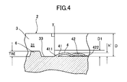
- FIG. 4 is an enlarged cross-sectional view of the tread for a pneumatic tire shown along the line III-III in FIG. 1, similar to FIG. 3, schematically showing the state of the flexible fence running on a wet road surface. .
- FIG. 4 is an enlarged cross-sectional view of the pneumatic tire tread, taken along the line III-III in FIG.
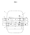
- FIG. 1 is a diagram schematically showing a tread for a pneumatic tire according to a first embodiment of the present invention
- FIG. 2 is an enlarged cross-sectional view of the tread for a pneumatic tire taken along line II-II in FIG.
- FIG. 3 is an enlarged cross-sectional view of the tread for a pneumatic tire viewed along line III-III in FIG.
- reference numeral 1 denotes a pneumatic tire 1 according to the present embodiment.
- This pneumatic tire 1 has a tread portion 2, and the tread portion 2 has a tire circumference indicated by XX ′.
- Two main grooves 3 having a width W extending in the direction are formed.
- the main groove 3 has three surfaces, that is, opposite wall surfaces 31, 32 and a bottom surface 33.
- the bottom 33 is provided with a shelf-like wear indicator 6 (see FIG. 5) provided to reduce the groove depth of the main groove. 3) is formed.
- the tire size in this example is 225 / 55R16, and the tire rotation direction of the tread portion 2 is not defined.
- the groove width W of the main groove 3 is 14.5 mm.
- This figure shows the tread tread surface 5 when the tire is filled with the rated internal pressure and the rated load is applied, and the tread tread length L at that time.
- the applicable rim of the size is 7 J
- the rated internal pressure is 250 kPa
- the rated load is 690 kg
- the tread length L is 143 mm.
- each main groove 3 passing through the tread tread surface 5 forms an air column with the road surface, and the resonance frequency of the main groove 3 is that of the air column thus formed.
- a flexible fence 4 having a width l is provided in the main groove 3 as shown in FIGS. 1 to 3 in order to change the frequency of the air column resonance sound by changing the length of the air column.
- the installation interval P of each flexible fence 4 formed in the same main groove 3 is such that at least one flexible fence is always in the tread surface 5 of each main groove 3 during tire rolling. As it exists, it is provided so as to have an interval shorter than the tread length L.
- the wear indicator 6 provided in the main groove 3 is formed in a shelf shape having a height that indicates the wear limit of the tire.
- the width l of the flexible fence 4 is 13.5 mm.
- the flexible fence 4 has a connection portion (edge portion) 411 with the bottom surface 33 of the main groove 3 and extends from the connection portion 411 at a predetermined angle.
- the outer portion 42 is configured to extend at a predetermined angle radially outward from the height D1 (predetermined height D1) from the bottom surface 33 of the main groove 3.
- the flexible fence 4 is provided so as to extend substantially outward in the tire radial direction (perpendicular to the tire rotation axis).
- the side surface portions 43 on both sides of the flexible fence 4, except for the connection portion 411 with the bottom surface 33 of the main groove 3 described above, are the entire wall surfaces 31, 32 facing the main groove 3. And a predetermined gap.
- each flexible fence 4 is formed such that the direction of its width l extends perpendicularly to the direction in which the main groove 3 extends. As shown in FIGS. 2 and 3, the inner portion 41 and the outer portion 42 of each flexible fence 4 have the width l and the thickness E described above. Further, as shown in FIG. 2, the flexible fence 4 is formed in a rectangular shape when viewed from the longitudinal direction of the main groove 3 (in front view), and as shown in FIGS. It has a slightly lower height h.
- the flexible fence 4 is formed so as to block at least 70% of the cross-sectional area of the main groove 3, and is formed so as to collapse due to water pressure mainly by a liquid such as water flowing in the main groove 3.
- the depth D of the main groove 3 is 8.0 mm
- the height h of the flexible fence 4 is 7.0 mm
- the thickness E of the flexible fence 4 is 0.6 mm
- the flexible fence 4 has a cross-sectional area of the main groove 3. About 87% of the total.
- the height TWI of the wear indicator 6 is 1.6 mm.
- the flexible fence 4 may have a shape having a height h of about 5.6 mm or more so as to block at least 70% of the cross-sectional area of the main groove 3.
- the inner portion 41 of the flexible fence 4 is mainly in a cross-sectional view in a plane parallel to the extending direction of the main groove 3 and perpendicular to the surface 5 that contacts the road surface of the tread portion 2.
- a straight line connecting a point (second end point) 412 that reaches (D1) has a first average inclination angle J1 with respect to a normal T of a surface that contacts the road surface of the tread portion 2.
- the outer portion 42 of the flexible fence 4 is also flexible in the cross-sectional view as shown in FIG. 3 and the second end point 412 having the height D1 from the bottom surface 33 of the main groove 3 of the flexible fence 4 as described above.
- the straight line connecting the outermost end portion (third end point) 422 in the tire radial direction of the outer portion 42 of the fence 4 is an angle of the perpendicular T of the surface in contact with the road surface of the tread portion 2 (assumed to be 0 degree).
- the height D1 (predetermined height D1) from the bottom surface 33 of the main groove 3 is less than 50% of the groove depth D of the main groove 3 and D1 ⁇ TWI + with respect to the height TWI of the wear indicator. It is 2.2 mm that satisfies the relationship of 1 mm, and the first average inclination angle J1 of the inner portion 41 of the flexible fence 4 is 65 degrees.
- the height D1 from the bottom surface 33 of the main groove 3 is flexible due to wear when the flexible fence 4 does not have the inner portion 41 and the outer portion 42 extends to the bottom surface 33 of the main groove 3.
- the predetermined height D1 from the bottom surface of the main groove temporarily assumes that the average inclination angle of the entire flexible fence is the same as the first average inclination angle J1 of the outer portion 42 defined in the present embodiment. Assuming that it is set and provided (the flexible fence is provided so as to extend at an angle perpendicular to the surface in contact with the road surface of the tread portion (an angle parallel to the perpendicular T of the surface in contact with the road surface of the tread portion 2).
- the height D1 is a height that should be changed according to the thickness E of the flexible fence 4, the material thereof, the groove width W and the groove depth D of the main groove 3 provided with the flexible fence 4, and the like. It is set as appropriate when designing the tire tread.
- the flexible fence 4 is made of the same material as the tread portion 2 of the pneumatic tire 1. In addition, you may make it comprise the flexible fence 4 with a material different from the tread part 2. FIG.
- the flexible fence 4 includes an outer portion 42 and an inner portion 41 having an average inclination angle J1 larger than the average inclination angle J2 of the outer portion 42. Accordingly, even when wear progresses and the height of the flexible fence 4 decreases, the same effect as that of the average inclination angle J1 of the inner portion 41 being large, that is, the flexible fence 4 being tilted in advance, is obtained. Therefore, when wear progresses, the flexible fence 4 can sufficiently collapse due to the water pressure generated by a liquid such as water that passes through the main groove 3, and the main column resonance sound is reduced while reducing the air column resonance noise. The drainage of the groove 3 can be more reliably ensured until the end of wear.
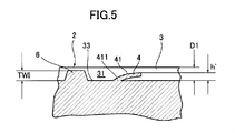
- FIG. 4 is an enlarged cross-sectional view showing a state in which the tread for a pneumatic tire is running on a wet road surface as viewed along the line III-III in FIG. 1, as in FIG. 3, and
- FIG. 3 is an enlarged cross-sectional view of the tread for a pneumatic tire, taken along line III-III in FIG. 1, as in FIG. 1.
- the tread portion is wetted with a groove depth of about 75%.
- the state where the vehicle is traveling on a rough road is schematically shown.
- the flexible fence 4 having the inner portion 41 and the outer portion 42 described above passes through the main groove 3 when traveling on a wet road surface, particularly when the tire is new or in the early stage of wear. It falls or bends due to the water pressure generated by the liquid, mainly water, and as a result, its height decreases to h ', and the main portion of the main groove 3 is released by the reduction of the height, Drainage is ensured.
- the flexible fence 4 is also reduced to the same height D1.
- the inner portion 41 having an average inclination angle J1 larger than the outer portion 42 of the flexible fence 4 is mainly water passing through the main groove 3. It becomes easy to collapse or bend by the water pressure generated by such a liquid.
- the height of the flexible fence 4 is reduced to h ′, and by reducing the height, it becomes possible to open the main part of the main groove 3, and the end of wear of the tread part 2. Drainage is ensured.
- Such a flexible fence can be formed by a method disclosed in, for example, International Publication No. WO2010 / 146180.
- FIG. 6 is an enlarged cross-sectional view of a tread for a pneumatic tire according to a second embodiment of the present invention, viewed along a position corresponding to line III-III in FIG.
- the basic configuration such as the shape and dimensions of the flexible fence 4 of the present embodiment is the same as that of the above-described first embodiment, and here, the configuration different from the above-described first embodiment will be mainly described.
- a main groove 3 having a groove depth D is formed in the tread portion 2 of the pneumatic tire 1.
- the flexible fence 4 includes the main groove 3 as in the first embodiment.
- An inner portion 41 having an end portion (first end point) 411 connected to the bottom surface 33 of the tire, and a tire radial direction from a point (second end point) of a height D1 (predetermined height D1) from the bottom surface of the main groove 3 It consists of an outer part 42 on the outer side.
- the inner portion 41 of the flexible fence 4 according to the present embodiment has an average inclination angle with respect to the normal T of the surface where the straight line connecting the first end point 411 and the second end point 412 contacts the road surface of the tread portion 2. J1 is provided.
- the outer portion 42 of the flexible fence 4 extends so that the straight line connecting the second end point 412 and the third end point 422 is inclined with respect to the normal T of the surface in contact with the road surface of the tread portion 2.
- it is provided so as to have an average inclination angle J2 as shown in FIG.
- the average inclination angle J1 of the inner portion 41 is provided to be larger than the inclination angle J2 of the outer portion 42.
- the average inclination angle J2 of the outer portion 42 is set to be smaller than 30 degrees.
- the average inclination angle J1 of the inner portion 41 in this embodiment is 69 degrees
- the average inclination angle J2 of the outer portion 42 is 20 degrees
- the height D1 from the bottom surface 33 of the main groove 3 is. Is 2.6 mm, which is less than 50% of the groove depth D of the main groove 3 and satisfies the relationship of D1 ⁇ TWI + 1 mm with respect to the height TWI of the wear indicator.
- the connection part 411 with the bottom face 33 of the main groove 3 of the flexible fence 4 is a part that extends in the vertical direction so as to improve the die-cutting property at the time of manufacture. (Mounting part) is provided.
- the functions and effects of the pneumatic tire tread according to the second embodiment of the present invention are basically the same as those of the first embodiment described above.
- the functions and effects unique to the second embodiment will be mainly described.
- the outer portion 42 of the flexible fence 4 since the outer portion 42 of the flexible fence 4 also has an average inclination angle J2 that is inclined with respect to the normal T of the surface that contacts the road surface of the tread portion 2, It is possible to ensure a good collapse property. Even when wear progresses and the height of the flexible fence 4 decreases, the average inclination angle J1 of the inner portion 41 is large, so that the same effect can be obtained as when the flexible fence 4 is collapsed in advance.
- the flexible fence 4 can be sufficiently collapsed by the water pressure generated by a liquid such as water that passes through the main groove 3, and the main groove 3 is reduced while reducing the air column resonance noise. It is possible to more reliably secure the drainage performance until the end of wear. Further, since the average inclination angle J2 of the outer portion 42 is set to be smaller than 30 degrees, it is possible to effectively block the air flow in the main groove 3 from the time when the tire is new to the beginning of wear or the middle of wear. . In addition, it is possible to effectively suppress the generation of air column resonance noise as described above, and to effectively obtain the ease of falling down of the flexible fence 4 by the water pressure of the water in the main groove 3 as described above.
- FIG. 7 is an enlarged cross-sectional view of a tread for a pneumatic tire according to a third embodiment of the present invention, viewed along a position corresponding to line III-III in FIG.
- the basic configuration such as the shape and dimensions of the flexible fence 4 of the present embodiment is the same as that of the first and second embodiments described above, and here, the configuration different from the first and second embodiments described above will be mainly described.
- a main groove 3 having a groove depth D is formed in the tread portion 2 of the pneumatic tire 1.
- the flexible fence 4 has a gentle curved shape (for example, an arc shape, A parabola, a spline curve, etc.). Even in this embodiment, even in the case of such a curved shape, an inner portion 41 having an end portion (first end point) 411 connected to the bottom surface 33 of the main groove 3 and a height from the bottom surface of the main groove 3. It is comprised by the outer part 42 of the tire radial direction outer side from the point (2nd end point) of D1 (predetermined height D1). In addition, the inner portion 41 of the flexible fence 4 according to the present embodiment has an average inclination angle with respect to the normal T of the surface where the straight line connecting the first end point 411 and the second end point 412 contacts the road surface of the tread portion 2.
- a gentle curved shape for example, an arc shape, A parabola, a spline curve, etc.
- the outer portion 42 of the flexible fence 4 has a straight line connecting the second end point 412 and the third end point 422 so as to have an average inclination angle J2 with respect to the normal T of the surface in contact with the road surface of the tread portion 2.
- the average inclination angle J1 of the inner portion 41 is provided to be larger than the inclination angle J2 of the outer portion 42 as in the first and second embodiments described above.
- the connecting portion 411 with the bottom surface 33 of the main groove 3 of the flexible fence 4 is provided with a very short attaching portion extending in the vertical direction. It has been.
- the average inclination angle J1 of the inner part 41 is 62 degrees
- the average inclination angle J2 of the outer part 42 is 23 degrees
- the height D1 from the bottom surface 33 of the main groove 3 is the height of the main groove 3. It is less than 50% of the groove depth D and 2.5 mm satisfying the relationship of D1 ⁇ TWI + 1 mm with respect to the wear indicator height TWI.
- the functions and effects of the tread for a pneumatic tire according to the third embodiment of the present invention are basically the same as those of the first and second embodiments described above, and here, the functions and effects unique to the third embodiment will be mainly described.
- the average inclination angle J1 of the inner part 41 is set to be larger than the average inclination angle J2 of the outer part 42.
- the flexible fence 4 Since the average inclination angle of the inner portion 41 is large even when the height of the flexible fence 4 is reduced, the same effect can be obtained as when the flexible fence 4 is collapsed in advance.
- the main groove 3 can be collapsed sufficiently by the water pressure generated by the liquid, mainly water, passing through the main groove 3, and the drainage of the main groove 3 is worn while reducing air column resonance noise. It can be secured more reliably until the end of the period.
- the flexible fence 4 as a whole an arcuate shape or a parabolic shape which is a gentle curve, the stress applied to the flexible fence 4 at the time of die cutting when manufacturing a pneumatic tire having such a flexible fence is obtained. It becomes possible to reduce, and productivity improves.
- FIG. 8 is an enlarged cross-sectional view of a tread for a pneumatic tire according to a fourth embodiment of the present invention, viewed along a position corresponding to line III-III in FIG.
- the basic configuration such as the shape and dimensions of the flexible fence 4 of the present embodiment is the same as that of the first to third embodiments described above, and here, the configuration different from the first to third embodiments described above will be mainly described. To do. As shown in FIG.
- a main groove 3 having a groove depth D is formed in the tread portion 2 of the pneumatic tire 1, and a concave portion 8 having a depth Dr from the bottom surface 33 is further formed on the bottom surface 33 of the main groove 3. Is formed.
- the recess 8 has an opening 81 and a bottom 82 that open to the main groove 3.
- the flexible fence 4 according to the present embodiment has the same basic configuration as that of the first embodiment, but the end portion (first end point) 411 of the inner portion 41 is connected to the bottom portion 82 of the concave portion 8 and is flexible.
- the fence 4 is configured to extend in the main groove 3 through the opening 81 of the recess 8.
- the inner portion 41 of the flexible fence 4 is provided so as to have an average inclination angle J1 with respect to the normal T of the surface that contacts the road surface of the tread portion 2, as in the second embodiment described above.
- the side portion 42 is provided so as to have an average inclination angle (0 degree) similar to the normal T of the surface in contact with the road surface of the tread portion 2, and the average inclination angle J1 of the inner portion 41 is the inclination of the outer portion 42. It is provided to be larger than the angle.
- the average inclination angle J1 of the inner portion 41 is 62 degrees
- the height D1 from the bottom surface 33 of the main groove 3 is less than 50% of the groove depth D of the main groove 3
- the height TWI of the wear indicator On the other hand, it is 1.5 mm that satisfies the relationship D1 ⁇ TWI + 1 mm
- the depth Dr from the bottom surface 33 of the main groove 3 of the recess 6 is 0.7 mm.
- the bottom surface 33 of the main groove 3 is provided with a recess 8 having an opening 81 that opens to the bottom surface 33 of the main groove 3, the flexible fence 4 is connected to the bottom 82 of the recess 8, and the opening of the recess 8 is opened. It extends in the main groove 3 through the portion 81.
- FIG. 9 is a view schematically showing a tread for a pneumatic tire according to a fifth embodiment of the present invention.
- the basic configuration such as the shape and dimensions of the flexible fence 4 of the present embodiment is the same as that of the first to fourth embodiments described above, and here, the configuration different from the first to fourth embodiments described above will be mainly described.
- reference numeral 1 denotes a pneumatic tire 1 according to the present embodiment.
- the pneumatic tire 1 has a tread portion 2, and the tread portion 2 has a tire circumferential direction indicated by XX ′.
- a plurality of main grooves 3 having a width W extending in an oblique direction are formed.
- the main groove 3 has three surfaces, that is, opposite wall surfaces 31, 32 and a bottom surface 33, and the bottom surface 33 of a part of the main grooves 3 has a shelf shape provided so as to reduce the groove depth of the main groove.
- a wear indicator 6 is provided.
- the tire rotation direction of the tread portion 2 is defined by an arrow R.
- a flexible fence 4 having a width l is formed so as to extend from the bottom surface 33 of the main groove 3.
- the surface is parallel to the direction in which the main groove 3 extends and contacts the road surface of the tread portion 2.
- the configuration is the same as that of the first to fourth embodiments described above in a cross-sectional view in a plane perpendicular to (see FIGS. 3 and 6 to 8).
- all of the plurality of flexible fences 4 have their inner portions 41 opposite to the prescribed rotational direction R of the tread portion 2 described above, that is, from the front to the rear in the prescribed rotational direction R.
- the height in the tire radial direction with respect to the bottom surface 33 of the main groove 3 is increased (not shown).
- the average inclination angle J2 of the outer portion 42 of the flexible fence 4 is set to be larger than 0 degrees as in the second and third embodiments described above, the front side in the rotational direction of the prescribed rotational direction R is also the same.
- the height in the tire radial direction with respect to the bottom surface 33 of the main groove 3 of the outer portion 42 is increased. That is, in the present embodiment, the average inclination angles J1 and J2 of the inner portion 41 and / or the outer portion 42 of the flexible fence 4 are inclined from the front side to the rear side in the prescribed rotational direction R. Formed.
- the direction of the angle of the flexible fence 4 is different between the one main groove 3 and the other main groove 3. Even in the tread portion 2 which is set in the direction and the tire rotation direction is not defined, a predetermined effect is exhibited.
- the tread portion 2 has a specified rotation direction R, and the height from the bottom surface 33 of the main groove 3 of the inner portion 41 of the flexible fence 4 provided in each main groove 3 is the specified rotation.
- the height of the specified rotational direction R is increased from the front side to the rear side, the direction in which the fluid flows inside the main groove 3 and the flexible fence 4 that is set in advance.
- the direction in which the flexible fence 4 collapses can be matched with the direction in which the fluid flows by matching the inclination direction of the inner portion 41 and / or the outer portion 42. Therefore, even when the height of the flexible fence 4 is reduced due to wear of the tread portion 2, it is possible to ensure a good collapse due to fluid pressure, so that the drainage of the main groove 3 is reduced while reducing air column resonance noise. It can be ensured more reliably until the end of wear.
- the inner portion 41 and / or the outer portion 42 of the flexible fence 4 may be further divided into portions having different shapes, for example, as long as it has the above-described action.
- the inner portion 41 on the straight line shown in FIG. 3 is curved and the outer portion 42 is set to be linear, or the shape (cross-sectional shape) along the width l falls down with water pressure and between the road surface and the road surface.
- the flexible fence 4 is difficult to bend (bend) on the surface viewed from the longitudinal direction (front view) of the main groove 3 of the flexible fence 4 so as to generate an appropriate ground pressure.
- (Rigidity) may be slightly provided, or may be formed in another shape such as a rectangular shape or a trapezoidal shape with rounded corners when viewed from the front.
- FIG. 10 is an enlarged cross-sectional view of a pneumatic tire tread provided with a flexible fence according to the prior art, and shows a state where the tread portion is running on a wet road surface with a groove depth of about 60% worn. It is a figure shown typically.
- the tire size in FIG. 10 is the same as that of the pneumatic tire tread according to the first embodiment.
- the flexible fence 104 is provided such that its end portion 141 is connected to the bottom surface 133 of the main groove 103 having the wall surface 131 and extends at an angle perpendicular to the surface that contacts the road surface of the tread portion 102. It is what was done.
- Reference numeral 106 denotes a wear indicator. As shown in FIG.
- the height of the flexible fence is reduced to D1 due to wear of the tread portion, but the flexible fence 104 of this example has an inner portion and an outer portion as in the above-described embodiments.
- the flexible fence 104 is unlikely to fall down in the vicinity of the connection end 141, and at the end of wear, the flexible fence 104 falls down due to the fluid pressure of the liquid passing through the main groove 103. It can be understood that it is difficult to carry.
- Both of the conventional tread models and pneumatic tire tread models according to Example 1 are provided with a main groove having a new groove depth of 8.0 mm and a groove width of 14.5 mm made of the same rubber material.
- a flexible fence with a thickness of 0.6 mm is formed so as to be connected to the bottom surface of the main groove, and each flexible fence is fully inserted into the main groove when it is new and the remaining groove depth is reduced to 2.0 mm due to wear.
- Each fluid pressure required to collapse was calculated. The calculated fluid pressure is displayed as an index with the conventional example being 100, and the larger the value, the better (the collapse is easier).
- the example product has good drainage until the end of wear of the tread portion, and the main groove is formed by the configuration of the tread for pneumatic tires of the first to fifth embodiments described above. It can be seen that it is possible to effectively achieve both reduction of air column resonance noise and drainage.
Landscapes
- Engineering & Computer Science (AREA)
- Mechanical Engineering (AREA)
- Tires In General (AREA)
Abstract
Description
また、主溝の排水性をトレッド部の摩耗末期まで確保することができる。即ち、フレキシブルフェンスの外方部分より平均傾斜角度の大きい内方部分は、水圧によって、より倒れ込み易くすることが出来るので、トレッド部の摩耗が進行してフレキシブルフェンスの高さが低くなっても、倒れ込みやすさを確保できる。その結果、摩耗末期まで排水性を確保することができるのである。
ここで、主溝の底面からの所定の高さD1は、仮に、フレキシブルフェンス全体の平均傾斜角度を、本発明で規定している外方部分の平均傾斜角度と同じ角度に設定して設けたと仮定した場合(フレキシブルフェンスが、トレッド部の路面と接触する面に垂直な角度で延びるよう設けられているような従来技術のものも含む)、摩耗によりフレキシブルフェンスの高さが減少したとき、主溝内に入り込んだ水の水圧によって、摩耗して高さが減少したフレキシブルフェンスが倒れこむことが難しくなる高さのことを言う(例えば、図10参照)。従って、内方部分のトレッド部の路面と接触する面の垂線に対する平均傾斜角度を、外方部分のトレッド部の路面と接触する面の垂線に対する平均傾斜角度より大きくなるよう構成することにより、摩耗末期まで、主溝の排水性を確保することが出来るのである(例えば、図5参照)。ここで、この所定の高さD1は、フレキシブルフェンス4の厚さEや、その材質、フレキシブルフェンス4の設けられる主溝3の溝幅Wや溝深さDが変わることにより変化し、適宜設定される。
このように構成された本発明においては、気柱共鳴音の低減を図りながら、排水性を確保し、その排水性をトレッド部の摩耗末期まで、より確実に確保することが出来る。即ち、フレキシブルフェンスの内方部分の平均傾斜角度を60度よりも小さくすると、トレッド部の摩耗によりフレキシブルフェンスの高さが低くなった際、フレキシブルフェンスの水圧による倒れ込みやすさを十分に確保することが難しくなり、トレッド部の摩耗進行と共に排水性が低下してしまう恐れがある。従って、フレキシブルフェンスの内方部分の平均傾斜角度を60度より大きくすれば、気柱共鳴音の低減を図りながら、排水性を確保し、その排水性をトレッド部の摩耗末期まで確保することが出来る。
このように構成された本発明においては、気柱共鳴音の低減を図りながら、排水性を確保し、その排水性をトレッド部の摩耗末期まで、より確実に確保することが出来る。即ち、主溝の底面からの所定高さD1を主溝の溝深さDの50%よりも大きくすると、摩耗末期での排水性の確保は可能なものの、外方部分を含むフレキシブルフェンス全体での、主溝内の空気の流れを遮ることによる気柱共鳴音の低減効果が得にくくなり、気柱共鳴音の低減効果とトレッド部の摩耗末期における排水性の確保の効果の両立が難しくなる恐れがある。
また、主溝の底面からの所定高さD1を主溝の溝深さDの50%よりも大きくすると、内方部分の平均傾斜角度を外方部分の平均傾斜角度より大きくするように構成していることに起因して、主溝が延びる方向にフレキシブルフェンスの長さが長くなり、フレキシブルフェンスの製造時に金型からの離形が難しくなるので、そのようなタイヤの生産性を低下させる恐れがある。
従って、主溝の底面からの所定高さD1を主溝の溝深さDの50%未満とすれば、生産性を確保しつつ、気柱共鳴音の低減の効果と、摩耗末期までの排水性の確保の効果との両立を、より確実に確保することが出来る。
このように構成された本発明においては、気柱共鳴音の低減を図りながら、排水性を確保し、その排水性をトレッド部の摩耗末期まで、より確実に確保することが出来る。即ち、主溝の底面からの所定高さD1を、ウエアインジケータの高さTWI+1mmよりも大きくすると、摩耗末期での排水性の確保は可能なものの、外方部分を含むフレキシブルフェンス全体での、主溝内の空気の流れを遮ることによる気柱共鳴音の低減効果が得にくくなり、気柱共鳴音の低減効果とトレッド部の摩耗末期における排水性の確保の効果の両立が難しくなる恐れがある。
また、所定高さD1を、ウエアインジケータの高さTWI+1mmよりも大きくすると、内方部分の平均傾斜角度を外方部分の平均傾斜角度より大きくするように構成していることに起因して、フレキシブルフェンスの長さが長くなり、フレキシブルフェンスの製造時に金型からの離形が難しくなるので、そのようなタイヤの生産性を低下させる恐れがある。
従って、主溝の底面からの所定高さD1が主溝の底面に形成された摩耗限度を示すウエアインジケータの高さをTWIとしたときD1≦TWI+1mmなる関係を満たすようにすれば、生産性を確保しつつ、気柱共鳴音の低減を図りながら、排水性を確保し、その排水性をトレッド部の摩耗末期までより確実に確保することが出来る。
このように構成された本発明においては、特に新品時、摩耗初期または摩耗中期にかけて、主溝の空気の流れをより確実に遮るようにすると共に、主溝内の水の水圧でフレキシブルフェンスの外方部分の倒れ込みやすさをより確実に確保することができるため、気柱共鳴音の低減を図りながら、排水性を確保し、その排水性をトレッド部の摩耗末期まで確保することが出来る。
このように構成された本発明においては、走行時、主溝内の流体の流れる方向とフレキシブルフェンスの内方部分の倒れ込む方向が同じ方向になるので、特にトレッド部の摩耗末期においてフレキシブルフェンスの内方部分の倒れ込みやすさをより確実に確保することができる。
このように構成された本発明においては、主溝内の流体の流れる方向とフレキシブルフェンスの外方部分の倒れ込む方向が同じ方向になるので、フレキシブルフェンスの外側部分の倒れ込みやすさをより確実に確保することができる。
このように構成された本発明においては、平均傾斜角度が0度となるように形成されたフレキシブルフェンスの外方部分は、最も効果的に気柱共鳴音の発生を抑制することができるので、より確実に、気柱共鳴音の低減を図りながら、排水性を確保することが出来る。
このように構成された本発明においては、フレキシブルフェンスの内方部分の接続部を主溝の底面よりも低くすることができるため、主溝内の流体の圧力によりフレキシブルフェンスが倒れ込んだ際の主溝の断面の開口割合をより大きくすることができ、その結果、より確実に、気柱共鳴音の低減を図りながら、排水性を確保し、その排水性をトレッド部の摩耗末期まで確保することが出来る。
このように構成された本発明においては、気柱共鳴音の低減を図りながら、排水性を確保し、その排水性を摩耗末期まで確保することができる。即ち、フレキシブルフェンスの厚さを0.3mmよりも小さくすると、フレキシブルフェンスの寸法的な剛性の低下により、空気圧によってもフレキシブルフェンスが倒れ込んでしまい、気柱共鳴音の低減効果が減少する恐れがある。一方、フレキシブルフェンスの厚さを2.0mmよりも大きくすると、フレキシブルフェンスが主溝内に倒れ込んだ際の主溝の断面の開口割合が小さくなり、排水性が低下する恐れがある。
先ず、図1及至図3により、本発明の第1実施形態による空気入りタイヤ用トレッドを説明する。
図1は、本発明の第1実施形態による空気入りタイヤ用トレッドを模式的に示す図であり、図2は、図1のII-II線に沿って見た空気入りタイヤ用トレッドの拡大断面図であり、図3は、図1のIII-III線に沿って見た空気入りタイヤ用トレッドの拡大断面図である。
先ず、図1に示すように、符号1は、本実施形態による空気入りタイヤ1を示し、この空気入りタイヤ1はトレッド部2を有し、トレッド部2には、XX‘にて示すタイヤ周方向に延びる幅Wの二本の主溝3が形成されている。主溝3は、3つの面、即ち、対向する壁面31,32及び底面33を有し、この底面33には主溝の溝深さを減じるように設けられた棚状のウエアインジケータ6(図3参照)が形成されている。なお、この例におけるタイヤサイズは225/55R16であり、トレッド部2のタイヤ回転方向は規定されていない。本実施形態においては、主溝3の溝幅Wは14.5mmである。
この図上には、タイヤが定格内圧に充填され、定格荷重が負荷された際のトレッド踏面5及びその際のトレッド踏面長さLが図示されている。なお”ETRTO STANDARD MANUAL 2011“によれば、当該サイズの適用リムは7J、定格内圧は250kPa、定格荷重は690kgであり、本実施形態においては、踏面長さLは143mmである。
また、図2に示すように、フレキシブルフェンス4は、主溝3の長手方向から見て(正面視)長方形状に形成され、図2及び図3に示すように、主溝3の深さDよりやや低い高さhを有している。
なお、例えば、本実施形態のタイヤの例において、フレキシブルフェンス4を、主溝3の断面積の少なくとも70%を遮断するように、およそ5.6mm以上の高さhを有する形状のものとしてもよい。なお、本実施形態の例に限らず、主溝3の溝幅W及び溝深さDが変われば、このフレキシブルフェンス4の高さhもそれに応じて変更して、主溝3の断面積の少なくとも70%を遮断するようにすればよい。
先ず、フレキシブルフェンス4の内方部分41は、図3に示すような、主溝3の延びる方向に平行、且つ、トレッド部2の路面と接触する面5に垂直な面における断面視において、主溝3の底面33との接続部(第1端点)411と、この接続部411から主溝3内に向けて延び、フレキシブルフェンス4が主溝3の底面33からの高さD1(所定の高さD1)に到達する点(第2端点)412とを結ぶ直線が、トレッド部2の路面と接触する面の垂線Tに対して第1平均傾斜角度J1を有している。
また、フレキシブルフェンス4の外方部分42は、同様に図3に示すような断面視において、上述してフレキシブルフェンス4の主溝3の底面33からの高さD1の第2端点412と、フレキシブルフェンス4の外方部分42のタイヤ半径方向における最も外側の端部(第3端点)422とを結ぶ直線が、トレッド部2の路面と接触する面の垂線Tの角度(0度とする)と同様の第2平均傾斜角度(J2)(0度)を有している。
本実施形態において、主溝3の底面33からの高さD1(所定高さD1)は、主溝3の溝深さDの50%未満かつウエアインジケータの高さTWIに対してD1≦TWI+1mmなる関係を満たす2.2mmであり、フレキシブルフェンス4の内方部分41の第1平均傾斜角度J1は65度である。
ここで、主溝3の底面33からの高さD1は、フレキシブルフェンス4が内方部分41を持たずに外方部分42が主溝3の底面33まで延びていたと仮定した時、摩耗によりフレキシブルフェンス4の高さが減じた際に、フレキシブルフェンス4が主溝3内を通過する主に水のような液体の発生する水圧によって倒れこむことが難しくなる高さである。言い換えると、主溝の底面からの所定の高さD1は、仮に、フレキシブルフェンス全体の平均傾斜角度を、本実施形態で規定している外方部分42の第1平均傾斜角度J1と同じ角度に設定して設けたと仮定した場合(フレキシブルフェンスが、トレッド部の路面と接触する面に垂直な角度(トレッド部2の路面と接触する面の垂線Tと平行な角度)で延びるよう設けられているような従来技術のものも含む)、摩耗によりフレキシブルフェンスの高さが減少したとき、主溝内に入り込んだ水の水圧によって、摩耗して高さが減少したフレキシブルフェンスが倒れこむことが難しくなる高さのことを言う(例えば、後述する図10参照)。この高さD1は、フレキシブルフェンス4の厚さEや、その材質、フレキシブルフェンス4の設けられる主溝3の溝幅Wや溝深さD等に応じて変更すべき高さであり、空気入りタイヤ用トレッドの設計時に適宜設定される。
本実施形態において、このフレキシブルフェンス4は、外方部分42と、外方部分42の平均傾斜角度J2よりも大きい平均傾斜角度J1を有する内方部分41とで構成されている。従って、摩耗が進行してフレキシブルフェンス4の高さが減少した場合でも、内方部分41の平均傾斜角度J1が大きいこと、即ち、フレキシブルフェンス4をあらかじめ倒しこんでおくこと、と同様の効果が得られるため、摩耗が進行したとき、フレキシブルフェンス4が主溝3内を通過する主に水のような液体の発生する水圧によって十分倒れこむことができ、気柱共鳴音を低減しながら、主溝3の排水性を摩耗末期までより確実に確保することができるものである。
図4は、図3と同様に示す、図1のIII-III線に沿って見た空気入りタイヤ用トレッドの濡れた路面を走行中の状態を示す拡大断面図であり、図5は、図3と同様に示す、図1のIII-III線に沿って見た空気入りタイヤ用トレッドの拡大断面図であり、この図5では、トレッド部の溝深さが約75%摩耗した状態で濡れた路面を走行中の状態を模式的に示す。
図6は、図1のIII-III線に相当する位置に沿って見た、本発明の第2実施形態による空気入りタイヤ用トレッドの拡大断面図である。本実施形態のフレキシブルフェンス4の形状及び寸法などの基本構成は、上述した第1実施形態と同様であり、ここでは、主に、上述した第1実施形態と異なる構成について主に説明する。
図6に示すように、空気入りタイヤ1のトレッド部2には溝深さDの主溝3が形成され、本実施形態では、第1実施形態と同様に、フレキシブルフェンス4は、主溝3の底面33に接続する端部(第1端点)411を有する内方部分41と、主溝3の底面からの高さD1(所定の高さD1)の点(第2端点)よりタイヤ半径方向外方の外方部分42とで構成されている。また、本実施形態によるフレキシブルフェンス4の内方部分41は、その第1端点411と第2端点412とを結ぶ直線が、トレッド部2の路面と接触する面の垂線Tに対して平均傾斜角度J1を有するように設けられている。一方、フレキシブルフェンス4の外方部分42は、その第2端点412と第3端点422とを結ぶ直線が、トレッド部2の路面と接触する面の垂線Tに対して傾斜して延び、本実施形態では、図6に示すような平均傾斜角度J2を有するように設けられている。本実施形態においても、第1実施形態と同様に、内方部分41の平均傾斜角度J1が外方部分42の傾斜角度J2よりも大きくなるように設けられている。また、外方部分42の平均傾斜角度J2は、30度より小さく設定される。
具体的には、本実施形態における内方部分41の平均傾斜角度J1は69度であり、外方部分42の平均傾斜角度J2は20度であり、主溝3の底面33からの高さD1は主溝3の溝深さDの50%未満かつウエアインジケータの高さTWIに対してD1≦TWI+1mmなる関係を満たす2.6mmである。
また、図6に示すように、本実施形態では、フレキシブルフェンス4の主溝3の底面33との接続部411は、製造時の型抜き性を良好にするようなごく短く垂直方向に延びる部分(取り付け部)が設けられている。
本実施形態では、フレキシブルフェンス4の外方部分42にもトレッド部2の路面と接触する面の垂線Tに対して傾斜する平均傾斜角度J2を持たせているので、摩耗初期からフレキシブルフェンス4の良好な倒れこみ性を確保することが可能となる。また、摩耗が進行してフレキシブルフェンス4の高さが減少した際でも、内方部分41の平均傾斜角度J1が大きいので、フレキシブルフェンス4をあらかじめ倒しこんでおく事と同様の効果が得られ、これにより、摩耗末期でも、フレキシブルフェンス4が、主溝3内を通過する主に水のような液体の発生する水圧によって十分倒れこむことができ、気柱共鳴音を低減しつつ、主溝3の排水性を摩耗末期までより確実に確保することができる。
また、外方部分42の平均傾斜角度J2は、30度より小さく設定されるので、特に、タイヤ新品時から摩耗初期または摩耗中期にかけて、主溝3の空気の流れを効果的に遮ることが出来る。また、そのようにして気柱共鳴音の発生を効果的に抑制すると共に、上述したように、主溝3内の水の水圧でフレキシブルフェンス4の倒れ込み易さも効果的に得ることが出来る。
図7は、図1のIII-III線に相当する位置に沿って見た、本発明の第3実施形態による空気入りタイヤ用トレッドの拡大断面図である。本実施形態のフレキシブルフェンス4の形状及び寸法などの基本構成は、上述した第1及び第2実施形態と同様であり、ここでは、上述した第1及び第2実施形態と異なる構成について主に説明する。
図7に示すように、空気入りタイヤ1のトレッド部2には溝深さDの主溝3が形成され、本実施形態では、フレキシブルフェンス4は全体としてなだらかな曲線状(例えば、円弧状、放物線状、スプライン曲線等)となるように構成されている。本実施形態においても、このような曲線状とした場合でも、主溝3の底面33に接続する端部(第1端点)411を有する内方部分41と、主溝3の底面からの高さD1(所定の高さD1)の点(第2端点)よりタイヤ半径方向外方の外方部分42とで構成されている。
また、本実施形態によるフレキシブルフェンス4の内方部分41は、その第1端点411と第2端点412とを結ぶ直線が、トレッド部2の路面と接触する面の垂線Tに対して平均傾斜角度J1を有するように設けられている。また、フレキシブルフェンス4の外方部分42は、その第2端点412と第3端点422とを結ぶ直線が、トレッド部2の路面と接触する面の垂線Tに対して平均傾斜角度J2を有するように設けられている。本実施形態においても、上述した第1及び第2の実施形態と同様に、内方部分41の平均傾斜角度J1が外方部分42の傾斜角度J2よりも大きくなるように設けられている。また、第2実施形態と同様に、製造時の型抜き性を良好にするために、フレキシブルフェンス4の主溝3の底面33との接続部411にはごく短く垂直方向に延びる取り付け部が設けられている。
本実施形態における内方部分41の平均傾斜角度J1は62度であり、外方部分42の平均傾斜角度J2は23度であり、主溝3の底面33からの高さD1は主溝3の溝深さDの50%未満かつウエアインジケータの高さTWIに対してD1≦TWI+1mmなる関係を満たす2.5mmである。
本実施形態では、このようななだらかな曲線状に形成されたフレキシブルフェンスであっても、内方部分41の平均傾斜角度J1が外方部分42の平均傾斜角度J2よりも大きくなるように設定されているので、上述した第1及び第2の実施形態と同様に、摩耗初期からフレキシブルフェンス4の良好な倒れこみ性を確保することが可能となるばかりでなく、摩耗が進行してフレキシブルフェンス4の高さが減少した際でも、内方部分41の平均傾斜角度が大きいので、フレキシブルフェンス4をあらかじめ倒しこんでおく事と同様の効果が得られ、これにより、摩耗末期でも、フレキシブルフェンス4が、主溝3内を通過する主に水のような液体の発生する水圧によって十分倒れこむことができ、気柱共鳴音を低減しつつ、主溝3の排水性を摩耗末期までより確実に確保することができる。
また、フレキシブルフェンス4を全体としてなだらかな曲線状である円弧状や放物線状等とすることで、そのようなフレキシブルフェンスを有する空気入りタイヤを製造する際の型抜き時にフレキシブルフェンス4にかかるストレスを減少させることが可能となり、生産性が向上する。
図8は、図1のIII-III線に相当する位置に沿って見た、本発明の第4実施形態による空気入りタイヤ用トレッドの拡大断面図である。本実施形態のフレキシブルフェンス4の形状及び寸法などの基本構成は、上述した第1及至第3実施形態と同様であり、ここでは、上述した第1及至第3実施形態と異なる構成について主に説明する。
図8に示すように、空気入りタイヤ1のトレッド部2には溝深さDの主溝3が形成され、主溝3の底面33には、更に、底面33からの深さDrの凹部8が形成されている。この凹部8は、主溝3に開口する開口部81及び底部82を有する。本実施形態におけるフレキシブルフェンス4は、第1実施形態と同様の基本構成としながらも、その内方部分41の端部(第1端点)411が、凹部8の底部82に接続されており、フレキシブルフェンス4は凹部8の開口部81を通って主溝3内で延びるように構成されている。
フレキシブルフェンス4の内方部分41は、上述した第2の実施形態と同様に、トレッド部2の路面と接触する面の垂線Tに対する平均傾斜角度J1を有するように設けられ、フレキシブルフェンス4の外方部分42は、トレッド部2の路面と接触する面の垂線Tと同様の平均傾斜角度(0度)を有するように設けられ、内方部分41の平均傾斜角度J1が外方部分42の傾斜角度よりも大きくなるように設けられている。なお、フレキシブルフェンス4の構成は、上述した第1実施形態や第3実施形態のように構成しても良い。
本実施形態における内方部分41の平均傾斜角度J1は62度であり、主溝3の底面33からの高さD1は主溝3の溝深さDの50%未満かつウエアインジケータの高さTWIに対してD1≦TWI+1mmなる関係を満たす1.5mmであり、凹部6の主溝3の底面33からの深さDrは0.7mmである。
本実施形態のように主溝3の底面33に、主溝3の底面33に開口する開口部81を有する凹部8を設け、フレキシブルフェンス4を凹部8の底部82に接続し、凹部8の開口部81を通って主溝3内で延びるようにしている。このような構成により、トレッド部2の摩耗の進行と共にフレキシブルフェンス4の高さが減少したときでも、フレキシブルフェンス4の流体圧による倒れ込みの際、その接続端部411の近傍の大きくたわむ部分を主溝3の底面33により近づける事が出来る。従って、流体圧によるフレキシブルフェンス4の倒れ込みの際、主溝3内での水が流れる断面積をより確実に確保することが可能になるのみならず、内方部分41の平均傾斜角度が大きいので、トレッド部2の摩耗によりフレキシブルフェンス4の高さが減少した場合でも流体圧による良好な倒れこみを確保することが出来る。従って気柱共鳴音を低減しながら、主溝3の排水性を摩耗末期までより確実に確保することができる。
図9は、本発明の第5実施形態による空気入りタイヤ用トレッドを模式的に示す図である。本実施形態のフレキシブルフェンス4の形状及び寸法などの基本構成は、上述した第1及至第4実施形態と同様であり、ここでは、上述した第1及至第4実施形態と異なる構成について主に説明する。
図9に示すように、符号1は、本実施形態による空気入りタイヤ1を示し、この空気入りタイヤ1はトレッド部2を有し、トレッド部2には、XX‘にて示すタイヤ周方向に対して斜め方向に延びる幅Wの複数の主溝3が形成されている。主溝3は、3つの面、即ち、対向する壁面31,32及び底面33を有し、一部の主溝3の底面33は主溝の溝深さを減じるように設けられた棚状のウエアインジケータ6を有する。トレッド部2のタイヤ回転方向は矢印Rにより規定されている。
各主溝3には、幅lを有するフレキシブルフェンス4が主溝3の底面33から延びるように形成され、図示しないが、主溝3の延びる方向に平行且つトレッド部2の路面と接触する面に垂直な面における断面視で、上述した第1乃至第4の実施形態と同様に構成される(図3、図6~8参照)。
本実施形態における、複数のフレキシブルフェンス4は、全て、その内方部分41が、上述したトレッド部2の規定の回転方向Rの反対方向、すなわち、規定の回転方向Rの回転方向前側から後ろ側に向けて、主溝3の底面33に対するタイヤ半径方向の高さが高くなるように形成されている(図示せず)。
なお、上述した第2及び第3の実施形態のように、フレキシブルフェンス4の外方部分42の平均傾斜角度J2を0度より大きく設定する場合も同様に、規定の回転方向Rの回転方向前側から後ろ側に向けて、外方部分42の主溝3の底面33に対するタイヤ半径方向の高さが高くなるように形成される。
即ち、本実施形態では、フレキシブルフェンス4の内方部分41及び/又は外方部分42の平均傾斜角度J1,J2が、規定の回転方向Rの回転方向前側から後ろ側に向けて角度が付くように形成される。
なお、上述した第1実施形態において、図1に例示した2つの主溝3では、このようなフレキシブルフェンス4の角度の向きが、一方の主溝3と他方の主溝3とで、互いに異なる向きに設定されており、タイヤ回転方向が規定されていないトレッド部2においても、所定の効果を発揮するようになっている。なお、図1に例示するような主溝3を有する空気入りタイヤ用トレッドにおいても、タイヤ回転方向が規定される場合は、本実施形態のように、全てのフレキシブルフェンス4を、規定の回転方向Rの回転方向前側から後ろ側に向けて、内方部分41及び/又は外方部分42の主溝3の底面33に対するタイヤ半径方向の高さが高くなるように、即ち、同じ向きに傾斜するように形成するのが好ましい。
本実施形態では、トレッド部2が規定の回転方向Rを有し、各主溝3に設けられたフレキシブルフェンス4の内方部分41の主溝3の底面33からの高さが、規定の回転方向Rの反対方向、すなわち、規定の回転方向Rの回転方向前側から後ろ側へと高くなるように形成することで、主溝3の内部を流体が流れる方向と、予め設定したフレキシブルフェンス4の内方部分41及び/又は外方部分42の傾斜方向とを一致させて、フレキシブルフェンス4が倒れこむ方向を流体の流れる方向と一致させることが出来る。従って、トレッド部2の摩耗によりフレキシブルフェンス4の高さが減少した場合でも流体圧による良好な倒れこみを確保することが出来るので、気柱共鳴音を低減しながら、主溝3の排水性を摩耗末期までより確実に確保することができる。
この図10に示す例では、フレキシブルフェンス104は、その端部141が、壁面131を有する主溝103の底面133に接続され、トレッド部102の路面と接触する面に垂直な角度で延びるよう設けられたものである。なお、符号106はウェアインジケータを示す。
図10に示すように、トレッド部の摩耗によりフレキシブルフェンスの高さはD1まで摩耗して減少しているが、この例のフレキシブルフェンス104では、上述した各実施形態のような内方部分と外方部分とを有する構成とされていないので、特に、接続端部141の近傍ではフレキシブルフェンス104が倒れにくくなり、摩耗末期において、フレキシブルフェンス104が、主溝103を通過する液体の流体圧で倒れこむことが難しくなっていることが理解できる。

2 トレッド部
3 主溝
31 主溝の対向する壁面
32 主溝の対向する壁面
33 主溝の底面
4 フレキシブルフェンス
41 フレキシブルフェンスの内方部分
42 フレキシブルフェンスの外方部分
411 内方部分の主溝の底面との接続部、端縁部(端部)、第1端点
412 所定高さD1の点、第2端点
422 外方部分のタイヤ半径方向における最も外側の端縁部(端部)、第3端点
5 トレッド踏面
6 ウェアインジケータ
8 主溝の底面の凹部
Claims (11)
- 底面及び対向する2つの壁面を有し、且つ、深さD及び幅Wを有する少なくとも一本の主溝が形成された、タイヤ転動時に路面と接触するトレッド部と、
フレキシブルフェンスであって、厚さEを有し、前記主溝の断面積の少なくとも70%を遮るように且つ前記主溝の底面から前記壁面と隙間を有するようにタイヤの半径方向外側方向に前記主溝内で延び、タイヤ転動時、トレッド踏面内の前記主溝内に少なくとも1つ存在するような間隔で配置された複数のフレキシブルフェンスと、を有する空気入りタイヤ用トレッドであって、
前記複数のフレキシブルフェンスは、前記主溝の底面に接続する端縁部を有する内方部分と、前記主溝の底面からの所定の高さD1より半径方向外方の外方部分と、を有し、前記主溝の延びる方向に平行、且つ、前記トレッド部の路面と接触する面に垂直な面における断面視において、前記内方部分の、前記トレッド部の路面と接触する面の垂線に対する平均傾斜角度が、前記外方部分の、前記トレッド部の路面と接触する面の垂線に対する平均傾斜角度より大きいことを特徴とする空気入りタイヤ用トレッド。 - 前記フレキシブルフェンスの内方部分の前記トレッド部の路面と接触する面の垂線に対する平均傾斜角度は60度より大きい請求項1に記載の空気入りタイヤ用トレッド。
- 前記主溝の底面からの所定の高さD1は溝深さDの50%未満である請求項1または請求項2に記載の空気入りタイヤ用トレッド。
- 前記主溝の底面にはさらに摩耗限度を示すウエアインジケータが形成され、前記主溝の底面からの所定の高さD1は、ウエアインジケータの高さをTWIとしたとき、D1≦TWI+1mmなる関係を満たすように設定される請求項1及至3の何れか1項に記載の空気入りタイヤ用トレッド。
- 前記フレキシブルフェンスの外方部分の前記トレッド部の路面と接触する面の垂線に対する平均傾斜角度は30度より小さい請求項1及至4の何れか1項に記載の空気入りタイヤ用トレッド。
- 前記トレッド部は規定の回転方向を有し、前記フレキシブルフェンスの内方部分は、前記トレッド部の既定の回転方向の前側から後ろ側に向けて、前記主溝の底面に対するタイヤ半径方向の高さが高くなるよう形成される請求項1及至5の何れか1項に記載の空気入りタイヤ用トレッド。
- 前記フレキシブルフェンスの外方部分は、前記トレッド部の既定の回転方向の前側から後ろ側に向けて、前記主溝の底面に対するタイヤ半径方向の高さが高くなるよう形成される請求項6に記載の空気入りタイヤ用トレッド。
- 前記フレキシブルフェンスの外方部分の前記トレッド部の路面と接触する面の垂線に対する平均傾斜角度は0度である請求項1及至6の何れか1項に記載の空気入りタイヤ用トレッド。
- 前記主溝の底面にはさらに前記主溝に開口する開口部を有する複数の凹部が形成され、前記複数のフレキシブルフェンスの内方部分は、前記主溝の底面の複数の凹部にそれぞれ接続され且つ前記凹部の開口部を通って前記主溝内で延びるように形成される請求項1及至8の何れか1項に記載の空気入りタイヤ用トレッド。
- 前記フレキシブルフェンスの厚さEが0.3mm以上2.0mm以下である請求項1及至9の何れか1項に記載の空気入りタイヤ用トレッド。
- 請求項1及至10の何れか1項に記載のトレッドを有することを特徴とする空気入りタイヤ。
Priority Applications (5)
| Application Number | Priority Date | Filing Date | Title |
|---|---|---|---|
| US14/385,844 US9962999B2 (en) | 2012-03-29 | 2012-03-29 | Tread for pneumatic tire |
| EP12872663.5A EP2837509B1 (en) | 2012-03-29 | 2012-03-29 | Tread for pneumatic tire |
| JP2014507170A JP6069713B2 (ja) | 2012-03-29 | 2012-03-29 | 空気入りタイヤ用トレッド |
| PCT/JP2012/058340 WO2013145204A1 (ja) | 2012-03-29 | 2012-03-29 | 空気入りタイヤ用トレッド |
| CN201280072081.5A CN104245362B (zh) | 2012-03-29 | 2012-03-29 | 充气轮胎胎面 |
Applications Claiming Priority (1)
| Application Number | Priority Date | Filing Date | Title |
|---|---|---|---|
| PCT/JP2012/058340 WO2013145204A1 (ja) | 2012-03-29 | 2012-03-29 | 空気入りタイヤ用トレッド |
Publications (1)
| Publication Number | Publication Date |
|---|---|
| WO2013145204A1 true WO2013145204A1 (ja) | 2013-10-03 |
Family
ID=49258568
Family Applications (1)
| Application Number | Title | Priority Date | Filing Date |
|---|---|---|---|
| PCT/JP2012/058340 Ceased WO2013145204A1 (ja) | 2012-03-29 | 2012-03-29 | 空気入りタイヤ用トレッド |
Country Status (5)
| Country | Link |
|---|---|
| US (1) | US9962999B2 (ja) |
| EP (1) | EP2837509B1 (ja) |
| JP (1) | JP6069713B2 (ja) |
| CN (1) | CN104245362B (ja) |
| WO (1) | WO2013145204A1 (ja) |
Families Citing this family (9)
| Publication number | Priority date | Publication date | Assignee | Title |
|---|---|---|---|---|
| CN107074028B (zh) * | 2014-11-12 | 2020-03-27 | 横滨橡胶株式会社 | 充气轮胎、充气轮胎的制造装置及制造方法 |
| FR3029843A1 (fr) * | 2014-12-12 | 2016-06-17 | Michelin & Cie | Dispositif attenuateur de bruit en roulage pour pneu |
| WO2017209159A1 (en) * | 2016-05-31 | 2017-12-07 | Compagnie Generale Des Etablissements Michelin | A noise reducing tread |
| AU2020220060A1 (en) | 2019-08-30 | 2021-03-18 | The Goodyear Tire & Rubber Company | Method for extracting changes in tyre characteristics |
| US11981163B2 (en) | 2019-08-30 | 2024-05-14 | The Goodyear Tire & Rubber Company | Tire wear state estimation system and method employing footprint shape factor |
| AU2020220054A1 (en) | 2019-08-30 | 2021-03-18 | The Goodyear Tire & Rubber Company | Tire wear state estimation system and method employing footprint length |
| US12220946B2 (en) | 2021-06-08 | 2025-02-11 | The Goodyear Tire & Rubber Company | Tire replacement forecasting system and method |
| US12263704B2 (en) | 2021-12-06 | 2025-04-01 | The Goodyear Tire & Rubber Company | Tire irregular wear detection system and method |
| US12589618B2 (en) | 2022-11-11 | 2026-03-31 | The Goodyear Tire & Rubber Company | Method and system for monitoring tire inflation pressure |
Citations (5)
| Publication number | Priority date | Publication date | Assignee | Title |
|---|---|---|---|---|
| JPH05155203A (ja) * | 1991-12-09 | 1993-06-22 | Sumitomo Rubber Ind Ltd | 空気入りタイヤ |
| JPH10250317A (ja) * | 1997-03-13 | 1998-09-22 | Bridgestone Corp | 重荷重用空気入りタイヤ |
| JP2006341655A (ja) | 2005-06-07 | 2006-12-21 | Yokohama Rubber Co Ltd:The | 空気入りタイヤ |
| WO2010146180A1 (fr) | 2009-06-19 | 2010-12-23 | Societe De Technologie Michelin | Dispositif amovible de moulage d'une paroi flexible dans un sillon de sculpture de pneumatique |
| WO2011089107A2 (fr) | 2010-01-19 | 2011-07-28 | Societe De Technologie Michelin | Bande de roulement de pneu comprenant un dispositif réducteur de bruit améliore |
Family Cites Families (13)
| Publication number | Priority date | Publication date | Assignee | Title |
|---|---|---|---|---|
| JPH04221207A (ja) * | 1990-12-21 | 1992-08-11 | Bridgestone Corp | 空気入りタイヤ |
| JPH08150812A (ja) * | 1994-11-30 | 1996-06-11 | Bridgestone Corp | 空気入りタイヤ |
| JP2002264614A (ja) * | 2001-03-13 | 2002-09-18 | Bridgestone Corp | タイヤ |
| JP2005053257A (ja) * | 2003-08-04 | 2005-03-03 | Yokohama Rubber Co Ltd:The | 空気入りタイヤ |
| DE102007032226B4 (de) * | 2007-07-11 | 2016-07-07 | Continental Reifen Deutschland Gmbh | Fahrzeugluftreifen |
| JP2009023505A (ja) * | 2007-07-19 | 2009-02-05 | Yokohama Rubber Co Ltd:The | 空気入りタイヤ |
| WO2009084666A1 (ja) * | 2007-12-28 | 2009-07-09 | Bridgestone Corporation | タイヤ |
| FR2939365B1 (fr) * | 2008-12-05 | 2012-03-16 | Michelin Soc Tech | Dispositif attenuateur de bruit pour bande de roulement. |
| JP5461043B2 (ja) * | 2009-03-30 | 2014-04-02 | 東洋ゴム工業株式会社 | タイヤ加硫用金型および空気入りタイヤ |
| KR20110064552A (ko) * | 2009-12-08 | 2011-06-15 | 한국타이어 주식회사 | 타이어의 수막현상 성능을 향상시킨 트레드 홈 |
| EP2517901B1 (en) * | 2009-12-25 | 2016-06-15 | Compagnie Générale des Etablissements Michelin | Pneumatic tire tread |
| JP5491956B2 (ja) * | 2010-05-13 | 2014-05-14 | 東洋ゴム工業株式会社 | 空気入りタイヤ |
| BR112013027657A8 (pt) * | 2011-04-28 | 2017-12-26 | Michelin & Cie | Pneumático |
-
2012
- 2012-03-29 US US14/385,844 patent/US9962999B2/en active Active
- 2012-03-29 EP EP12872663.5A patent/EP2837509B1/en active Active
- 2012-03-29 JP JP2014507170A patent/JP6069713B2/ja not_active Expired - Fee Related
- 2012-03-29 CN CN201280072081.5A patent/CN104245362B/zh active Active
- 2012-03-29 WO PCT/JP2012/058340 patent/WO2013145204A1/ja not_active Ceased
Patent Citations (5)
| Publication number | Priority date | Publication date | Assignee | Title |
|---|---|---|---|---|
| JPH05155203A (ja) * | 1991-12-09 | 1993-06-22 | Sumitomo Rubber Ind Ltd | 空気入りタイヤ |
| JPH10250317A (ja) * | 1997-03-13 | 1998-09-22 | Bridgestone Corp | 重荷重用空気入りタイヤ |
| JP2006341655A (ja) | 2005-06-07 | 2006-12-21 | Yokohama Rubber Co Ltd:The | 空気入りタイヤ |
| WO2010146180A1 (fr) | 2009-06-19 | 2010-12-23 | Societe De Technologie Michelin | Dispositif amovible de moulage d'une paroi flexible dans un sillon de sculpture de pneumatique |
| WO2011089107A2 (fr) | 2010-01-19 | 2011-07-28 | Societe De Technologie Michelin | Bande de roulement de pneu comprenant un dispositif réducteur de bruit améliore |
Non-Patent Citations (1)
| Title |
|---|
| See also references of EP2837509A4 |
Also Published As
| Publication number | Publication date |
|---|---|
| EP2837509B1 (en) | 2018-03-21 |
| EP2837509A4 (en) | 2016-01-13 |
| US9962999B2 (en) | 2018-05-08 |
| EP2837509A1 (en) | 2015-02-18 |
| CN104245362A (zh) | 2014-12-24 |
| JPWO2013145204A1 (ja) | 2015-08-03 |
| JP6069713B2 (ja) | 2017-02-01 |
| CN104245362B (zh) | 2016-10-26 |
| US20150246586A1 (en) | 2015-09-03 |
Similar Documents
| Publication | Publication Date | Title |
|---|---|---|
| JP6069713B2 (ja) | 空気入りタイヤ用トレッド | |
| JP6362597B2 (ja) | タイヤ | |
| JP6125142B2 (ja) | 空気入りタイヤ | |
| WO2016075922A1 (ja) | 空気入りタイヤ | |
| JP6887908B2 (ja) | タイヤ | |
| WO2008075630A1 (ja) | 空気入りタイヤ | |
| EP2602127A1 (en) | Tire | |
| WO2018235464A1 (ja) | タイヤ | |
| JP5852167B2 (ja) | タイヤ | |
| JP5814042B2 (ja) | 空気入りタイヤ | |
| CN105459734B (zh) | 充气轮胎 | |
| JP5815685B2 (ja) | 空気入りタイヤ | |
| JP2013244854A (ja) | 空気入りタイヤ | |
| JP2010023760A (ja) | タイヤ | |
| JP6329010B2 (ja) | 空気入りタイヤ | |
| WO2014083758A1 (ja) | 空気入りタイヤ | |
| JP2011245996A (ja) | 空気入りタイヤ | |
| JP6060221B2 (ja) | 空気入りタイヤ | |
| JP6571993B2 (ja) | 空気入りタイヤ | |
| JP7081998B2 (ja) | 空気入りタイヤ | |
| JP6334441B2 (ja) | タイヤ | |
| JP2019093916A (ja) | 空気入りタイヤ | |
| JP6579805B2 (ja) | 空気入りタイヤ | |
| JP6012442B2 (ja) | 空気入りタイヤ |
Legal Events
| Date | Code | Title | Description |
|---|---|---|---|
| 121 | Ep: the epo has been informed by wipo that ep was designated in this application |
Ref document number: 12872663 Country of ref document: EP Kind code of ref document: A1 |
|
| ENP | Entry into the national phase |
Ref document number: 2014507170 Country of ref document: JP Kind code of ref document: A |
|
| NENP | Non-entry into the national phase |
Ref country code: DE |
|
| WWE | Wipo information: entry into national phase |
Ref document number: 2012872663 Country of ref document: EP |
|
| REG | Reference to national code |
Ref country code: BR Ref legal event code: B01A Ref document number: 112014024176 Country of ref document: BR |
|
| WWE | Wipo information: entry into national phase |
Ref document number: 14385844 Country of ref document: US |
|
| ENP | Entry into the national phase |
Ref document number: 112014024176 Country of ref document: BR Kind code of ref document: A2 Effective date: 20140929 |