WO2013145222A1 - Dispositif de traitement d'informations et programme de traitement de stockage de données - Google Patents
Dispositif de traitement d'informations et programme de traitement de stockage de données Download PDFInfo
- Publication number
- WO2013145222A1 WO2013145222A1 PCT/JP2012/058423 JP2012058423W WO2013145222A1 WO 2013145222 A1 WO2013145222 A1 WO 2013145222A1 JP 2012058423 W JP2012058423 W JP 2012058423W WO 2013145222 A1 WO2013145222 A1 WO 2013145222A1
- Authority
- WO
- WIPO (PCT)
- Prior art keywords
- data
- server
- data center
- processing unit
- response time
- Prior art date
- Legal status (The legal status is an assumption and is not a legal conclusion. Google has not performed a legal analysis and makes no representation as to the accuracy of the status listed.)
- Ceased
Links
Images










Classifications
-
- H—ELECTRICITY
- H04—ELECTRIC COMMUNICATION TECHNIQUE
- H04L—TRANSMISSION OF DIGITAL INFORMATION, e.g. TELEGRAPHIC COMMUNICATION
- H04L67/00—Network arrangements or protocols for supporting network services or applications
- H04L67/01—Protocols
- H04L67/10—Protocols in which an application is distributed across nodes in the network
- H04L67/1097—Protocols in which an application is distributed across nodes in the network for distributed storage of data in networks, e.g. transport arrangements for network file system [NFS], storage area networks [SAN] or network attached storage [NAS]
-
- H—ELECTRICITY
- H04—ELECTRIC COMMUNICATION TECHNIQUE
- H04L—TRANSMISSION OF DIGITAL INFORMATION, e.g. TELEGRAPHIC COMMUNICATION
- H04L67/00—Network arrangements or protocols for supporting network services or applications
-
- H—ELECTRICITY
- H04—ELECTRIC COMMUNICATION TECHNIQUE
- H04L—TRANSMISSION OF DIGITAL INFORMATION, e.g. TELEGRAPHIC COMMUNICATION
- H04L67/00—Network arrangements or protocols for supporting network services or applications
- H04L67/01—Protocols
- H04L67/10—Protocols in which an application is distributed across nodes in the network
- H04L67/1001—Protocols in which an application is distributed across nodes in the network for accessing one among a plurality of replicated servers
- H04L67/1004—Server selection for load balancing
- H04L67/1008—Server selection for load balancing based on parameters of servers, e.g. available memory or workload
-
- H—ELECTRICITY
- H04—ELECTRIC COMMUNICATION TECHNIQUE
- H04L—TRANSMISSION OF DIGITAL INFORMATION, e.g. TELEGRAPHIC COMMUNICATION
- H04L67/00—Network arrangements or protocols for supporting network services or applications
- H04L67/01—Protocols
- H04L67/10—Protocols in which an application is distributed across nodes in the network
- H04L67/1001—Protocols in which an application is distributed across nodes in the network for accessing one among a plurality of replicated servers
- H04L67/1004—Server selection for load balancing
- H04L67/101—Server selection for load balancing based on network conditions
Definitions
- the present invention relates to an information processing apparatus and a data storage processing program.
- cloud computing in which computer resources (for example, servers, storage, applications, etc.) are used via a network.
- computer resources for example, servers, storage, applications, etc.
- a user performs various operations using a client such as a personal computer.
- the data is saved on a cloud server that provides the service.
- the client When storing data in the cloud server, the client normally stores data in a predetermined data center in the cloud server.
- An object of the present invention is to reduce the time required for the storage process.
- the information processing apparatus can communicate with a plurality of servers, and includes a storage unit, a division unit, a storage destination determination unit, and a transmission unit.
- the storage unit transmits a network response table in which a network response time, which is a time from transmission of a connection request to the server to reception of a response to the connection request, and a data write request to the server is transmitted, and then the write A server response table in which a server response time, which is a time until receiving a completion response, is described.
- the dividing unit divides write data and generates divided data.
- the storage destination determination unit determines a storage destination server that stores the divided data based on the network response time or the server response time.
- the transmission unit transmits the divided data to the storage destination server.
- the time required for the storage process can be reduced.
- FIG. 1 is a configuration diagram of a system according to an embodiment. It is a block diagram of the client which concerns on embodiment. It is a figure which shows the example of data center structure information. It is a figure which shows the example of a NW response table. It is a figure which shows the example of the sorted NW response table. It is a figure which shows the example of a server response table. It is a figure which shows the example of the sorted server response table. It is an example of the sorted free disk capacity table. It is an example of a data division condition table. It is an example of a divided data management table. It is a block diagram of the management server which concerns on embodiment. It is an example of a free disk capacity table. It is a block diagram of the data center which concerns on embodiment.
- FIG. 1 is a configuration diagram of a system according to an embodiment.
- the client 201, the management server 301, and the data center 401 are connected via a network and can communicate with each other.
- the client 201 executes various processes and stores data in the data center 401.
- the client 201 is an information processing apparatus such as a personal computer or a mobile terminal.
- the management server 301 collects and manages information of the data center 301.
- the data center 401 is a server that stores data.
- the data center 401 writes and reads data requested from the client 201.
- the data centers 401-1 to 401-6 are assigned data center-a to data center-f as server IDs, respectively.
- the server ID is an identifier that identifies the data center 401.
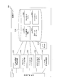
- FIG. 2 is a configuration diagram of the client according to the embodiment.
- the client 201 includes a data center configuration information acquisition unit 211, a dummy data write request processing unit 212, a network (NW) response table processing unit 213, a server response table processing unit 214, a sort table reception processing unit 215, a data division processing unit 216, A data storage destination determination processing unit 217, a data reading / writing processing unit 218, a transmission / reception control unit 219, and a storage unit 220 are provided.
- NW network
- the data center configuration information acquisition unit 211 acquires the data center configuration information 321 from the management server 301 and stores it in the storage unit 220 as the data center configuration information 232.
- the dummy data write request processing unit 212 transmits a connection request and a dummy data write request to the data center 401.
- the NW response table processing unit 213 measures the NW response time and generates the NW response table 233.
- the server response table processing unit 214 measures the server response time and generates the server response table 235.
- the sort table reception processing unit 215 receives the sorted NW response table, the sorted server response table, and the sorted free disk capacity table and stores them in the storage unit 220.
- the data division processing unit 216 divides the write data 231 and generates divided data.
- the data storage destination determination processing unit 217 determines (selects) a storage destination data center for storing the divided data based on at least one of the network response time, the server response time, and the free disk capacity.
- the data storage destination determination processing unit 217 determines, for example, a predetermined number (for example, 10) of data centers as the storage destination data center in order of increasing network response time.
- the data storage destination determination processing unit 217 determines, for example, a predetermined number (for example, 10) of data centers as the storage destination data center in order of increasing server response time.
- the data storage destination determination processing unit 217 does not determine, for example, a data center whose free disk capacity is a predetermined capacity or less as a storage destination data center. That is, the data storage destination determination processing unit 217 determines a data center having a free disk capacity larger than a predetermined capacity as the storage destination data center.
- the data storage destination determination processing unit 217 cyclically selects (assigns) a storage destination data center for each divided data. Cyclic selection means that the storage destination data center is selected from the list of storage destination data centers arranged in order of network response time or server response time in order from the top, and when the end of the list is reached, Returning to the beginning (wraparound), selecting in turn again.
- the data storage destination determination processing unit 217 stores the storage destination data centers ⁇ ⁇ ⁇ ⁇ ⁇ ⁇ ⁇ ⁇ ⁇ ⁇ for each divided data. Select in the order of ⁇ ⁇ .
- the data storage destination determination processing unit 217 creates the divided data management table 239.
- the data read / write processing unit 218 transmits the divided data to the data center 401 and receives the divided data from the data center 401. Further, the data reading / writing processing unit 218 combines the received divided data.
- the transmission / reception control unit 219 includes a data center configuration information acquisition unit 211, a dummy data write request processing unit 212, an NW response table processing unit 213, a server response table processing unit 214, a sort table reception processing unit 215, a data division processing unit 216, data Data is received from the storage destination determination processing unit 217 and the data read / write processing unit 218, and the data is transferred to the management server 301 or the data center 401. Also, the transmission / reception control unit 219 receives data from the management server 301 or the data center 401, and transmits the data to the data center configuration information acquisition unit 211, dummy data write request processing unit 212, NW response table processing unit 213, server response table processing. The data is transferred to the unit 214, sort table reception processing unit 215, data division processing unit 216, data storage destination determination processing unit 217, or data read / write processing unit 218.
- the storage unit 220 is a device that stores data.
- the storage unit 220 is, for example, a magnetic disk device, a semiconductor storage device, or a random access memory (RAM).
- the storage unit 220 includes write data 231, data center configuration information 232, network (NW) response table 233, sorted NW response table 234, server response table 235, sorted server response table 236, sorted free disk capacity table 237, A data division condition table 238 and a divided data management table 239 are stored.
- the write data 231 is data before division written in the data center 401.
- the write data 231 is generated by application software that operates on the client 201, for example.
- the data center configuration information 232 is information on the data center 401 in the system 101.
- FIG. 3 is a diagram illustrating an example of data center configuration information.
- the data center configuration information 232 includes, as items, a server ID, an Internet Protocol (IP) address, and a Uniform Resource Locator (URL).
- IP Internet Protocol
- URL Uniform Resource Locator
- the server ID is an identifier that identifies the data center 401.
- the IP address is the IP address of the data center 401.
- the URL is the URL of the data center 401.
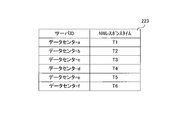
- the network (NW) response table 233 is a table in which the network response time between the client 201 and the data center 401 is described.
- the network response time is the time from when the client 201 transmits a connection request (SYN packet) to the data center 401 until it receives an acknowledgment (ACK packet). Details of the network response time will be described later.
- FIG. 4 is a diagram illustrating an example of the NW response table.
- the NW response table 233 includes a server ID and an NW response time as items.
- the server ID and the NW response time are described in association with each other.
- the server ID is an identifier that identifies the data center 401.
- the NW response time is a network response time between the client 201 and the data center 401.
- the unit of NW response time is milliseconds (ms).
- the sorted NW response table 234 is a table in which records of the NW response table 322 described later are sorted in ascending order of NW response time.
- FIG. 5 is a diagram illustrating an example of a sorted NW response table.
- the sorted NW response table 234 has a server ID and an NW response time as items.
- the server ID and the NW response time are described in association with each other.
- the server ID is an identifier that identifies the data center 401.
- the NW response time is a network response time between the client 201 and the data center 401.
- the unit of NW response time is milliseconds (ms).
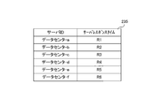
- the server response table 235 is a table in which the server response time between the client 201 and the data center 401 is described.
- the server response time is the time from when the client 201 sends a dummy data write request to the data center 401 until it receives a response. Details of the server response time will be described later.
- FIG. 6 is a diagram illustrating an example of a server response table.
- the server response table 235 has a server ID and a server response time as items.
- a server ID and a server response time are described in association with each other.
- the server ID is an identifier that identifies the data center 401.
- the server response time is a server response time between the client 201 and the data center 401.
- the unit of the server response time is milliseconds (ms).
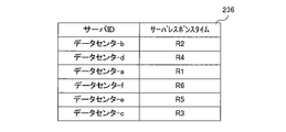
- the sorted server response table 236 is a table in which records in a server response table 323 described later are sorted in ascending order of server response time.
- FIG. 7 is a diagram illustrating an example of a sorted server response table.
- the sorted server response table 236 includes a server ID and a server response time as items.
- the server ID and the server response time are described in association with each other.
- the server ID is an identifier that identifies the data center 401.
- the server response time is a server response time between the client 201 and the data center 401.
- the unit of the server response time is milliseconds (ms).
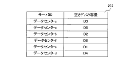
- the sorted free disk capacity table 237 is a table in which records of a free disk capacity table 324 described later are sorted in descending order of free disk capacity.
- the sorted free disk capacity table 237 is a table in which the free disk capacity of the data center 401 is described.
- FIG. 8 is an example of a sorted free disk capacity table.
- the sorted free disk capacity table 237 includes a server ID and a free disk capacity as items.
- the server ID and the free disk capacity are described in association with each other.
- the server ID is an identifier that identifies the data center 401.
- the free disk capacity is the size of the free area of the storage unit provided in the data center 401.
- the unit of the free disk capacity is gigabyte (GB).
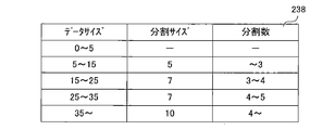
- the data division condition table 238 is a table in which a policy when the data division processing unit 216 divides data is described.
- FIG. 9 is an example of a data division condition table.
- the data division condition table 238 includes data size, division size, and number of divisions as items.
- the data size, the division size, and the number of divisions are described in association with each other.
- the data size indicates the size of the data to be divided.
- the unit of data size is megabyte (MB).
- the division size indicates the size of the divided data.
- the unit of the division size is MB.
- the number of divisions indicates the number of divided data when the data to be divided is divided by the division size.
- the second line of the data division condition table 238 in FIG. 9 divides the data to be divided every 5 MB when the size of the data to be divided is larger than 5 MB and 15 MB or less, thereby dividing the data into 3 or less. Indicates that data will be generated.
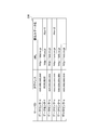
- the divided data management table 239 is a table in which information indicating the storage destination of divided data is described.
- FIG. 10 is an example of a divided data management table.
- the divided data management table 239 has, as items, a server ID, an IP address, a URL, and a write file name.
- a server ID, an IP address, a URL, and a write data name are described in association with each other.
- the server ID is an identifier that identifies the data center 401.
- the IP address is the IP address of the data center 401.
- the URL is the URL of the data center 401.
- the write data name is the name (file name) of the divided write data (divided data).
- the format of the write data name is “name of write data 231” ⁇ “division number”.
- the division number is a number assigned to the divided data in order. For example, the write data name “Abc-1” indicates the first data among the data obtained by dividing the write data 231 whose name is “Abc”.
- the second row of the divided data management table 239 indicates that the divided data with the name “Abc-1” is stored in the data center with the server ID “data center-f”. That is, it indicates that the first data among the data obtained by dividing the write data 231 with the name “Abc” is stored in the data center with the server ID “data center-f”.
- FIG. 11 is a configuration diagram of the management server according to the embodiment.
- the management server 301 includes a data center configuration information processing unit 311, NW response table processing unit 312, server response table processing unit 313, free disk capacity table processing unit 314, disk capacity inquiry processing unit 315, sort processing unit 316, transmission / reception control A unit 317 and a storage unit 318.
- the data center configuration information processing unit 311 transmits the data center configuration information 321 to the client 201.
- the NW response table processing unit 312 receives the NW response table 233 from the client 201 and stores it in the storage unit 318 as the NW response table 322.
- the server response table processing unit 313 receives the server response table 235 from the client 201 and stores it in the storage unit 318 as the server response table 323.
- the free disk capacity table processing unit 314 creates and updates the free disk capacity table 324.
- the disk capacity inquiry processing unit 315 queries the data center 401 for the free disk capacity and acquires information on the free disk capacity.
- the sort processing unit 316 sorts the records of the NW response table 322, the server response table 323, and the free disk capacity table 324.
- the transmission / reception control unit 317 includes the data center configuration information processing unit 311, the NW response table processing unit 312, the server response table processing unit 313, the free disk capacity table processing unit 314, the disk capacity inquiry processing unit 315, and the sort processing unit 316.
- Data is received, and the data is transferred to the client 201 or the data center 401.
- the transmission / reception control unit 317 receives data from the client 201 or the data center 401 and transmits the data to the data center configuration information processing unit 311, the NW response table processing unit 312, the server response table processing unit 313, and the free disk capacity table processing unit. 314, and transfer to the disk capacity inquiry processing unit 315 or sort processing unit 316.
- the storage unit 318 is a device that stores data.
- the storage unit 318 is, for example, a magnetic disk device, a semiconductor storage device, or a RAM.
- the storage unit 318 stores data center configuration information 321, NW response table 322, server response table 323, and free disk capacity table 324.
- the data center configuration information 321 is information on the data center 401 in the system 101. Since the format of the data center configuration information 321 is the same as that of the data center configuration information 232 described above, description thereof is omitted.
- the NW response table 322 is a table in which the network response time between the client 201 and the data center 401 is described. Since the format of the NW response table 322 is the same as that of the above-described NW response table 233, description thereof is omitted.
- the server response table 323 is a table in which the server response time between the client 201 and the data center 401 is described.
- the server response time is the time from when the client 201 sends a dummy data write request to the data center 401 until it receives a response. Details of the server response time will be described later. Since the format of the server response table 323 is the same as the server response table 235 described above, the description thereof is omitted.
- the free disk capacity table 324 is a table in which the size of the free disk capacity of the data center 401 is described.
- FIG. 12 is an example of a completed free disk capacity table.
- the free disk capacity table 324 includes a server ID and a free disk capacity as items. In the free disk capacity table 324, the server ID and the free disk capacity are described in association with each other.
- the server ID is an identifier that identifies the data center 401.
- the free disk capacity is the size of the free area of the storage unit provided in the data center 401.
- the unit of the free disk capacity is gigabyte (GB).
- FIG. 13 is a configuration diagram of a data center according to the embodiment.
- the data center 401-1 includes a disk capacity check processing unit 411, a data reading processing unit 412, a data writing processing unit 413, a dummy data writing processing unit 414, a transmission / reception control unit 415, a network interface card (NIC) 416, and a storage unit 417. Is provided.
- NIC network interface card
- the disk capacity check processing unit 411 checks the size of the free capacity in the storage unit 417.
- the data read processing unit 412 reads data from the storage unit 417.
- the data write processing unit 413 writes data in the storage unit 417.
- the dummy data write processing unit 414 writes the dummy data 401 into the storage unit 401.
- the dummy data is data having a small size (for example, 100 bytes).
- the contents of the dummy data are arbitrary.
- the transmission / reception control unit 415 receives data from the disk capacity check processing unit 411, the data read processing unit 412, the data write processing unit 413, and the dummy data write processing unit 414, and transfers the data to the NIC 416.
- the transmission / reception control unit 415 receives data from the NIC 416 and transfers the data to the disk capacity check processing unit 411, the data read processing unit 412, the data write processing unit 413, or the dummy data write processing unit 414.
- the NIC 416 is an expansion card that connects to the network and communicates with the client 201 and the management server 301.
- the NIC 416 receives data from the client 201 or the management server 301 and transfers it to the transmission / reception control unit 415. In addition, data is received from the transmission / reception control unit 415 and transferred to the client 201 or the management server 301.
- the NIC 416 transmits an acknowledgment (ACK packet) to the connection request (SYN packet) to the client 201.
- ACK packet acknowledgment
- SYN packet connection request
- the storage unit 417 is a device that stores data.
- the storage unit 417 is, for example, a magnetic disk device, a semiconductor storage device, or a RAM.
- the storage unit 417 stores the divided data 421.
- the divided data 421 is a part of the divided write data 231.
- the configuration of the data centers 401-2 to 401-6 is the same as that of the data center 401-1 and will not be described.
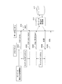
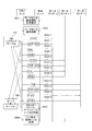
- FIG. 14 is a sequence diagram of measurement processing of network response time and server response time.
- TCP Transmission Control Protocol
- the client 201 starts dummy data write processing. First, the client 201 transmits a connection request (SYN packet) to the data center 401-1 (S 501).
- the NIC 416 transmits an acknowledgment (ACK packet) to the connection request to the client 201 (S502).
- the client 201 receives an acknowledgment (ACK packet).
- the client 201 measures the time from when the client 201 transmits a connection request (SYN packet) until it receives an acknowledgment (ACK packet), and uses that time as the network response time.
- the client 201 transmits a dummy data write request to the data center 401-1 using HyperText Transfer Protocol (HTTP) or Hypertext Transfer Protocol over Secure Socket Layer (HTTPS) (S503).
- HTTP HyperText Transfer Protocol
- HTTPS Hypertext Transfer Protocol over Secure Socket Layer
- the dummy data write processing unit 414 When the dummy data write processing unit 414 receives the dummy data write request, the dummy data write processing unit 414 writes the dummy data into the storage unit 417. When the writing is completed, the dummy data writing processing unit 414 responds to the client 201 with the writing completion (S504).
- the client 201 receives a write completion response.
- the client 201 measures the time from when the client 201 sends a dummy data write request until it receives a write completion response, and uses this time as the server response time.
- the client 201 transmits a FIN packet to the data center 401-1 and ends the communication (S505).
- network response time and server response time measurement processes of the data centers 401-2 to 401-6 are the same as the network response time and server response time measurement processes of the data center 401-1 described above.
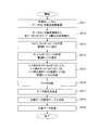
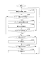
- FIG. 15 is a flowchart of client data storage processing according to the embodiment.
- the client 201 generates write data 231 through processing by application software, and starts data storage processing for storing the write data 231.
- step S 511 the data center configuration information acquisition processing unit 211 transmits a data center configuration information acquisition request to the management server 301, receives the data center configuration information 321 from the management server 301, and stores the data center configuration information 232 as the storage unit 220. To store.
- step S 512 the dummy data write request processing unit 212 executes dummy data write processing for each data center 401 described in the data center configuration information 232, and the NW response time and server response time of each data center 401. Measure.
- the NW response table processing unit 213 creates the NW response table 233. Specifically, the NW response table processing unit 213 describes the server ID and the measured NW response time in the NW response table 233 in association with each other. Then, the NW response table processing unit 213 transmits the NW response table 233 to the management server 301.
- step S514 the server response table processing unit 214 creates the server response table 235. Specifically, the server response table processing unit 214 describes the server ID and the measured server response time in the server response table 235 in association with each other. Then, the server response table processing unit 214 transmits the server response table 235 to the management server 301.
- step S515 the sort table reception processing unit 215 receives the sorted NW response table, the sorted server response table, and the sorted free disk capacity table from the management server 301.
- the sorted NW response table 234, the sorted server The response table 235 and the sorted free disk capacity table 237 are stored in the storage unit 220.
- step S516 the data division processing unit 216 refers to the data division condition table 238, divides the write data 231 according to the conditions described in the data division condition table 238, and generates divided data.
- the data storage destination determination processing unit 217 refers to at least one of the sorted NW response table 234, the sorted server response table 235, and the sorted free disk capacity table 237, and stores the divided data.
- a data center is determined based on a predetermined condition. Predetermined conditions include NW response time priority, server response time priority, and free disk capacity larger than a threshold.
- the data center that stores the divided data is called a storage destination data center. An example of determining the storage destination data center will be described later.
- step S518, the data storage destination determination processing unit 217 creates the divided data management table 239. Specifically, the data storage destination determination processing unit 217 describes the server ID of the storage destination data center and the name of the divided data in the divided data management table 239 in association with each other.
- step S519 the data reading / writing processing unit 217 transmits the divided data to the storage destination data center based on the divided data management table 239, respectively.
- step S5 Details processing from acquisition of the data center configuration information (step S511) to reception of the sorted table (step S515) will be described.
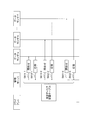
- FIG. 16 is a sequence diagram from the acquisition of the data center configuration information to the acquisition of the sorted table according to the embodiment.
- FIG. 16 corresponds to steps S511 to S515 in FIG.
- the data center configuration information acquisition processing unit 211 transmits a data center configuration information acquisition request to the management server 301 (step S521).
- the data center configuration information processing unit 311 When receiving the data center configuration information acquisition request, the data center configuration information processing unit 311 transmits the data center configuration information 321 to the client 201 (step S522), and the data center configuration information acquisition processing unit 211 receives the data center configuration information 321. Receive.
- the data center configuration information acquisition processing unit 211 stores the received data center configuration information 321 in the storage unit 220 as the data center configuration information 232.
- the dummy data write request processing unit 212 transmits a connection request (SYN packet) to the data center 401-1 (S523-1).
- the NIC 416 transmits an acknowledgment (ACK packet) to the connection request to the client 201 (S524-1).
- the NW response table processing unit 213 measures the time from when the connection request (SYN packet) is transmitted to the data center 401-1 to when the confirmation response (ACK packet) is received, and the time is stored in the data center 401-1.
- the network response time is described in the NW response table 233.
- the dummy data write request processing unit 212 transmits a dummy data write request to the data center 401-1 using HTTP or HTTPS (S 525-1).
- the dummy data write processing unit 414 When the dummy data write processing unit 414 receives the dummy data write request, the dummy data write processing unit 414 writes the dummy data into the storage unit 417. When the writing is completed, the dummy data writing processing unit 414 responds to the client 201 with the writing completion (S526-1).
- the server response table processing unit 214 measures the time from when the client 201 sends a dummy data write request until it receives a write completion response, and uses this time as the server response time of the data center 401-1 It is described in the table 235.
- the NW response time and server response time of the data centers 401-2 to 401-6 are measured, and the measured NW response time and server response time of the data centers 401-2 to 401-6 are measured in the NW response table 233 and Each is described in the server response time table 235 (steps S523-2 to S526-6).
- the NW response table processing unit 213 After creating the NW response table 233 and the server response time table 235, the NW response table processing unit 213 transmits the NW response table 233 to the management server 301, and the server response table processing unit 214 sends the server response table 235 to the management server 301. (Step S527).
- the sort table reception processing unit 215 receives the sorted NW response table, the sorted server response table, and the sorted free disk capacity table from the management server 301, and sorts the NW response table 234 and the sorted server response table. 235 and the sorted free disk capacity table 237 are stored in the storage unit 220 (step S528).
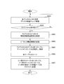
- FIG. 17 is a flowchart of processing of the management server according to the embodiment.
- the disk capacity inquiry unit 315 checks the free disk capacity of each data center 401. Specifically, the disk capacity inquiry unit 315 transmits a free disk capacity check request for inquiring about the free disk capacity to each data center 401. The disk capacity inquiry unit 315 receives a free disk capacity response (size of free disk capacity) from each data center 401.
- the free disk capacity table processing unit 314 describes the received free disk capacity information in the free disk capacity table 324. Acquisition of free disk capacity information is performed periodically (for example, every hour). Details of obtaining information on the free disk capacity will be described later.
- step S602 if there is a data center configuration information acquisition request from the client 201, the control proceeds to step S603, and if there is no data center configuration information acquisition request, the control returns to step S601.
- step S603 the data center configuration information processing unit 311 receives a data center configuration information acquisition request from the client 201.
- step S604 the data center configuration information processing unit 311 transmits the data center configuration information 321 to the client 201.
- step S605 the NW response table processing unit 312 receives the NW response table 233 from the client 201 and stores it in the storage unit 318 as the NW response table 322.
- the server response table processing unit 313 receives the server response table 235 from the client 201 and stores it in the storage unit 318 as the server response table 323.
- step S606 the sort processing unit 316 sorts the NW response table 322 in ascending order of network response time, and generates a sorted NW response table.
- the sort processing unit 316 sorts the server response table 323 in ascending order of server response time, and generates a sorted server response table.
- the sort processing unit 316 sorts the free disk capacity table 324 in descending order of free disk capacity, and generates a sorted free disk capacity table.
- step S607 the NW response table processing unit 312 transmits the sorted NW response table to the client 201.
- the server response table processing unit 313 transmits the sorted server response table to the client 201.
- the free disk capacity table processing unit 314 transmits the sorted free disk capacity table to the client 201.
- FIG. 18 is a sequence diagram of the free disk capacity information acquisition processing according to the embodiment.
- FIG. 18 corresponds to step S601 in FIG.
- the disk capacity inquiry unit 315 transmits a free disk capacity check request for inquiring about the free disk capacity to the data center 401-1 (step S 611-1).
- the disk capacity inquiry unit 315 receives a free disk capacity response (size of free disk capacity) from each data center 401-1 (step S 612-1).
- the free disk capacity table processing unit 314 describes the received information on the free disk capacity of the data center 401-1 in the free disk capacity table 324.
- the disk capacity inquiry unit 315 sequentially transmits free disk capacity check requests from the data center 401-2 to the data center 401-6, and information on the free disk capacity of the data centers 401-2 to 401-6. Is described in the free disk capacity table 324 (steps S611-2 to S612-6).
- FIG. 19 is a flowchart of client response processing in the data center according to the embodiment.
- step S701 the NIC 416 receives a connection request (SYN packet) from the client 201, and transmits an acknowledgment (ACK packet) to the client 201.
- SYN packet connection request
- ACK packet acknowledgment
- step S702 if the data center 401-1 receives the dummy data write request, the control proceeds to step S703, and if the dummy data write request is not received, the control proceeds to step S706.
- step S703 the dummy data write processing unit 414 receives a dummy data write request from the client 201.
- step S704 the dummy data write processing unit 414 writes the dummy data in the storage unit 417. Then, the dummy data write processing unit 414 responds to the client 201 with the write completion.
- step S705 if the data center 401-1 receives a data read request or data write request, control proceeds to step S706. If no data read request or data write request is received, control returns to step S701.
- step S706 if the data read processing unit 412 receives a data read request, the control proceeds to step S707, and if the data read processing unit 412 does not receive a data read request, the control proceeds to step S708.
- step S707 the data read processing unit 412 reads the data requested by the data read request from the storage unit 417, and transmits the read data to the client 201.
- step S708 if the data write processing unit 413 receives a data write request, the control proceeds to step S709, and if the data write processing unit 413 does not receive data write, the control returns to step S701.
- the data write processing unit 413 receives the divided data as data to be written in the storage unit 417.
- step S709 the data write processing unit 413 writes the received divided data in the storage unit 417.
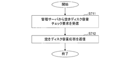
- FIG. 20 is a flowchart of management server response processing of the data center according to the embodiment.
- the disk capacity check processing unit 411 receives the free disk capacity check request from the management server 301, and checks the free disk capacity of the storage unit 417 (step S711).
- the disk capacity check processing unit 411 returns the size of the free disk capacity in the storage unit 417 to the management server 301 as a free disk capacity response (step S712).
- the name of the write data 231 is “Abc”
- the write data 231 is divided, and two divided data are created.
- the names of the two divided data are “Abc-1” and “Abc-2”, respectively.
- the number of data centers used as the storage destination data center is three.
- FIG. 21 is a diagram showing a sorted free disk capacity table.
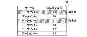
- FIG. 22 is a diagram showing a sorted NW response table.
- the sorted free disk capacity table 237-1 and the sorted NW response table 234-1 are as shown in FIGS. 21 and 22, respectively.
- the data center configuration information 232 is as shown in FIG.
- the data storage destination determination processing unit 217 refers to the free disk capacity table 237-1, and sets a data center whose free disk capacity is a predetermined value or less (for example, 10G or less) as a target. By excluding data centers whose free disk capacity is equal to or less than a predetermined value from the storage destination data center, it is possible to modify or write existing data stored in the data center.
- a predetermined value or less for example, 10G or less
- the data storage destination determination processing unit 217 refers to the NW response table 234-1, and reflects the information of the data center that is not subject to the NW response table 234-1. That is, the data center-a and data center-d of the NW response table 234-1 are set as excluded.
- the data storage destination determination processing unit 217 creates the divided data management table 239-1 shown in FIG. 23 from the data center configuration information 232 and the sorted NW response table 234-1. However, data is not described in the write data name.
- the server IDs are arranged in order of increasing NW response time.
- the data storage destination determination processing unit 217 stores the three data centers in the descending order of NW response time among the data centers other than the data centers set as excluded from the divided data management table 239-1. Choose as. That is, the data center-f, the data center-c, and the data center-b are selected.
- the divided data is allocated in the order of NW response time.
- the divided data “Abc-1” and “Abc-2” are allocated to the data center-f and the data center-c, respectively.
- the data storage destination determination processing unit 217 describes “Abc-1” and “Abc-2” in the write data names corresponding to the data center-f and data center-c of the divided data management table 239-1, respectively. As a result, a divided data management table 239-1 as shown in FIG. 23 is created. The data storage destination determination processing unit 217 stores the divided data management table 239-1 in the storage unit 220 in association with the data name “Abc”.
- the data read / write processing unit 218 transmits the divided data “Abc-1” and “Abc-2” to the data center 401-6 and the data center 401-3, respectively.
- the name of the write data 231 is “Def”
- the write data 231 is divided, and three divided data are created.
- the names of the three divided data are “Def-1”, “Def-2”, and “Def-3”, respectively.
- the number of data centers used as the storage destination data center is three.
- FIG. 24 is a diagram showing a sorted free disk capacity table.
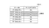
- FIG. 25 is a diagram illustrating a sorted server response table.
- the sorted free disk capacity table 237-2 and the sorted server response table 236-2 are as shown in FIGS. 24 and 25, respectively.
- the data center configuration information 232 is as shown in FIG.
- the data storage destination determination processing unit 217 refers to the free disk capacity table 237-2 and sets a data center whose free disk capacity is a predetermined value or less (for example, 10G or less) as a target. By excluding data centers whose free disk capacity is equal to or less than a predetermined value from the storage destination data center, it is possible to modify or write existing data stored in the data center.
- a predetermined value or less for example, 10G or less
- the data storage destination determination processing unit 217 refers to the server response table 236-2, and reflects the information of the data center that is excluded from the server response table 236-2. That is, the data center-a and data center-d of the server response table 236-2 are set as excluded.
- the data storage destination determination processing unit 217 creates a divided data management table 239-1 shown in FIG. 26 from the data center configuration information 232 and the sorted server response table 236-2. However, data is not described in the write data name.
- the server IDs are arranged in order of server response time.
- the data storage destination determination processing unit 217 stores the three data centers in the order of the server response time in the data center excluding the data center set as the non-target in the divided data management table 239-2. Choose as. That is, the data center-b, the data center-f, and the data center-e are selected.
- the divided data is allocated in the order of NW response time.
- the divided data “Def-1”, “Def-2”, and “Def-3” are allocated to the data center-b, the data center-f, and the data center-e, respectively.
- the data storage destination determination processing unit 217 assigns “Def-1”, “Def-2”, and “Def-3” to the data center-b, data center-f, and data center-of the divided data management table 239-2. Describe each write data name corresponding to e. Thereby, a divided data management table 239-2 as shown in FIG. 26 is created.
- the data storage destination determination processing unit 217 stores the divided data management table 239-2 in the storage unit 220 in association with the data name “Def”.
- the data read / write processing unit 218 transfers the divided data “Def-1”, “Def-2”, and “Def-3” to the data center 401-2, the data center 401-6, and the data center 401-5. Send each one.
- the data read / write processing unit 218 reads the divided data from the data center 401 and combines the divided data. Thereby, data before division is generated.
- the data read / write processing unit 218 refers to the divided data management table 239-1 associated with the data name “Abc”.
- the divided data “Abc-1” and “Abc-2” are stored in the data center 401-6 and the data center 401-3, respectively. is described.
- the data read / write processing unit 218 reads the divided data “Abc-1” and “Abc-2” from the data center 401-6 and the data center 401-3, respectively, and divides the divided data “Abc-1”. Data “Abc-2” is combined to generate data “Abc” before division.
- the data read / write processing unit 218 refers to the divided data management table 239, identifies the data center 401 that stores the divided data, reads the divided data from the identified data center 401, and obtains the divided data. Combine and generate pre-split data.
- the client can select a data center that does not take time for the storage process.
- the load on a specific data center can be reduced by dividing the data into a plurality of data and storing the data in different data centers.
- FIG. 27 is a configuration diagram of an information processing apparatus (computer).
- the client 201, the management server 301, and the data center 401 according to the embodiment are realized by an information processing apparatus 1 as illustrated in FIG. 27, for example.
- the information processing apparatus 1 includes a CPU 2, a memory 3, an input unit 4, an output unit 5, a storage unit 6, a recording medium drive unit 7, and a network connection unit 8, which are connected to each other by a bus 9.
- the CPU 2 is a central processing unit that controls the entire information processing apparatus 1.
- the CPU 2 includes a data center configuration information acquisition unit 211, a dummy data write request processing unit 212, an NW response table processing unit 213, a server response table processing unit 214, a sort table reception processing unit 215, a data division processing unit 216, and a data storage destination determination.
- the memory 3 is a Read Only Memory (ROM) or Random Access Memory (RAM) that temporarily stores a program or data stored in the storage unit 6 (or the portable recording medium 10) during program execution. It is memory.
- the CPU 2 executes the various processes described above by executing a program using the memory 3.
- the program code itself read from the portable recording medium 10 or the like realizes the functions of the embodiment.
- the input unit 4 is, for example, a keyboard, a mouse, a touch panel, or the like.
- the output unit 5 is, for example, a display, a printer, or the like.
- the storage unit 6 is, for example, a magnetic disk device, an optical disk device, a tape device, or the like.
- the information processing apparatus 1 stores the above-described program and data in the storage unit 6 and reads them into the memory 3 and uses them as necessary.
- the memory 3 or the storage unit 6 corresponds to the storage units 220, 318, and 417.
- the recording medium driving unit 7 drives the portable recording medium 10 and accesses the recorded contents.
- the portable recording medium any computer-readable recording medium such as a memory card, a flexible disk, a compact disk read only memory (CD-ROM), an optical disk, and a magneto-optical disk is used.
- the user stores the above-described program and data in the portable recording medium 10 and reads them into the memory 3 and uses them as necessary.
- the network connection unit 8 is connected to an arbitrary communication network such as a LAN, and performs data conversion accompanying communication.
- the network connection unit 8 corresponds to the NIC 416.
Landscapes
- Engineering & Computer Science (AREA)
- Computer Networks & Wireless Communication (AREA)
- Signal Processing (AREA)
- Computer Hardware Design (AREA)
- General Engineering & Computer Science (AREA)
- Information Retrieval, Db Structures And Fs Structures Therefor (AREA)
Abstract
Les données sont segmentées en une pluralité de données segmentées. Sur la base de temps de réponse de réseau et de temps de réponse de serveur, une destination de centre de données de stockage est établie à partir d'une pluralité de centres de données. Le temps de traitement de stockage est réduit au minimum en stockant les données segmentées dans le centre de données établi.
Priority Applications (2)
| Application Number | Priority Date | Filing Date | Title |
|---|---|---|---|
| PCT/JP2012/058423 WO2013145222A1 (fr) | 2012-03-29 | 2012-03-29 | Dispositif de traitement d'informations et programme de traitement de stockage de données |
| US14/481,157 US20140379792A1 (en) | 2012-03-29 | 2014-09-09 | Information processing apparatus and recording medium |
Applications Claiming Priority (1)
| Application Number | Priority Date | Filing Date | Title |
|---|---|---|---|
| PCT/JP2012/058423 WO2013145222A1 (fr) | 2012-03-29 | 2012-03-29 | Dispositif de traitement d'informations et programme de traitement de stockage de données |
Related Child Applications (1)
| Application Number | Title | Priority Date | Filing Date |
|---|---|---|---|
| US14/481,157 Continuation US20140379792A1 (en) | 2012-03-29 | 2014-09-09 | Information processing apparatus and recording medium |
Publications (1)
| Publication Number | Publication Date |
|---|---|
| WO2013145222A1 true WO2013145222A1 (fr) | 2013-10-03 |
Family
ID=49258586
Family Applications (1)
| Application Number | Title | Priority Date | Filing Date |
|---|---|---|---|
| PCT/JP2012/058423 Ceased WO2013145222A1 (fr) | 2012-03-29 | 2012-03-29 | Dispositif de traitement d'informations et programme de traitement de stockage de données |
Country Status (2)
| Country | Link |
|---|---|
| US (1) | US20140379792A1 (fr) |
| WO (1) | WO2013145222A1 (fr) |
Cited By (1)
| Publication number | Priority date | Publication date | Assignee | Title |
|---|---|---|---|---|
| JP2017111800A (ja) * | 2015-12-10 | 2017-06-22 | 新日鉄住金ソリューションズ株式会社 | 情報処理装置、認可システム、情報処理方法及びプログラム |
Citations (3)
| Publication number | Priority date | Publication date | Assignee | Title |
|---|---|---|---|---|
| JP2006146294A (ja) * | 2004-11-16 | 2006-06-08 | Dainippon Printing Co Ltd | データ保管制御システム |
| JP2006350470A (ja) * | 2005-06-13 | 2006-12-28 | National Institute Of Advanced Industrial & Technology | データ管理装置および方法 |
| WO2009089426A1 (fr) * | 2008-01-10 | 2009-07-16 | Diskeeper Corporation | Sélection d'emplacements de stockage pour stockage de fichiers sur la base de la longévité et de la vitesse de stockage |
Family Cites Families (7)
| Publication number | Priority date | Publication date | Assignee | Title |
|---|---|---|---|---|
| JP4113352B2 (ja) * | 2001-10-31 | 2008-07-09 | 株式会社日立製作所 | ストレージ・ネットワークにおけるストレージ・リソース運用管理方法 |
| JP4601969B2 (ja) * | 2004-01-27 | 2010-12-22 | 株式会社日立製作所 | ファイル入出力制御装置 |
| JP2005266933A (ja) * | 2004-03-16 | 2005-09-29 | Fujitsu Ltd | ストレージ管理システム及びストレージ管理方法 |
| CN101300542A (zh) * | 2005-11-04 | 2008-11-05 | 汤姆逊许可证公司 | 用于管理媒体存储装置的方法和设备 |
| JP2008123132A (ja) * | 2006-11-09 | 2008-05-29 | Hitachi Ltd | 記憶制御装置及び記憶制御装置の論理ボリューム形成方法 |
| JP5316723B2 (ja) * | 2010-08-23 | 2013-10-16 | 富士通株式会社 | データ記憶装置およびデータ記憶装置制御方法 |
| JP5825359B2 (ja) * | 2011-12-19 | 2015-12-02 | 富士通株式会社 | 負荷分散システム |
-
2012
- 2012-03-29 WO PCT/JP2012/058423 patent/WO2013145222A1/fr not_active Ceased
-
2014
- 2014-09-09 US US14/481,157 patent/US20140379792A1/en not_active Abandoned
Patent Citations (3)
| Publication number | Priority date | Publication date | Assignee | Title |
|---|---|---|---|---|
| JP2006146294A (ja) * | 2004-11-16 | 2006-06-08 | Dainippon Printing Co Ltd | データ保管制御システム |
| JP2006350470A (ja) * | 2005-06-13 | 2006-12-28 | National Institute Of Advanced Industrial & Technology | データ管理装置および方法 |
| WO2009089426A1 (fr) * | 2008-01-10 | 2009-07-16 | Diskeeper Corporation | Sélection d'emplacements de stockage pour stockage de fichiers sur la base de la longévité et de la vitesse de stockage |
Cited By (1)
| Publication number | Priority date | Publication date | Assignee | Title |
|---|---|---|---|---|
| JP2017111800A (ja) * | 2015-12-10 | 2017-06-22 | 新日鉄住金ソリューションズ株式会社 | 情報処理装置、認可システム、情報処理方法及びプログラム |
Also Published As
| Publication number | Publication date |
|---|---|
| US20140379792A1 (en) | 2014-12-25 |
Similar Documents
| Publication | Publication Date | Title |
|---|---|---|
| ES2553428T3 (es) | Método, dispositivo y sistema de procesamiento de contenidos | |
| US10474691B2 (en) | Micro-staging device and method for micro-staging | |
| JP2022500775A (ja) | 分散型システムのデータ同期方法、装置、コンピュータプログラム、及び電子機器 | |
| CN108881348B (zh) | 服务质量控制方法、装置和存储服务器 | |
| JP2005122235A (ja) | 通信バッファ予約機能を備えるストレージ装置およびシステム | |
| CN102130959A (zh) | 一种实现云存储资源调度的系统及方法 | |
| US9836358B2 (en) | Ephemeral remote data store for dual-queue systems | |
| US8341285B2 (en) | Method and system for transferring files | |
| KR20200017589A (ko) | 무선 통신 시스템에서 모바일 노드의 태스크를 오프로딩하기 위한 클라우드 서버 및 그의 동작 방법 | |
| US9781023B2 (en) | Information processing device, information processing method, and recording medium | |
| US20140222896A1 (en) | Distributed processing system and management method of distributed processing system | |
| US11394800B2 (en) | Systems and methods for remote network topology discovery | |
| US20170153909A1 (en) | Methods and Devices for Acquiring Data Using Virtual Machine and Host Machine | |
| JP2019016042A (ja) | データ取得プログラム、装置、及び方法 | |
| CN109478171A (zh) | 提高openfabrics环境中的吞吐量 | |
| JP2021039802A (ja) | データ処理システム、及びデータ処理方法 | |
| JP7305990B2 (ja) | 転送プログラム、転送方法、および情報処理装置 | |
| JP6886874B2 (ja) | エッジ装置、データ処理システム、データ送信方法、及びプログラム | |
| CN116401227B (zh) | 一种集群配置方法、装置、设备及介质 | |
| US10970250B2 (en) | System, data management method, and file server | |
| US10516628B2 (en) | Transfer device, transfer system, and transfer method | |
| CN103108045B (zh) | 基于云架构的Web地图服务实现方法 | |
| Nethaji et al. | Differential Grey Wolf Load‐Balanced Stochastic Bellman Deep Reinforced Resource Allocation in Fog Environment | |
| US20140289307A1 (en) | Method for transmitting data between electronic devices | |
| WO2013145222A1 (fr) | Dispositif de traitement d'informations et programme de traitement de stockage de données |
Legal Events
| Date | Code | Title | Description |
|---|---|---|---|
| 121 | Ep: the epo has been informed by wipo that ep was designated in this application |
Ref document number: 12872647 Country of ref document: EP Kind code of ref document: A1 |
|
| ENP | Entry into the national phase |
Ref document number: 2014507188 Country of ref document: JP Kind code of ref document: A |
|
| NENP | Non-entry into the national phase |
Ref country code: DE |
|
| 122 | Ep: pct application non-entry in european phase |
Ref document number: 12872647 Country of ref document: EP Kind code of ref document: A1 |