WO2013145351A1 - 照明ランプ用レンズ板および照明ランプ - Google Patents
照明ランプ用レンズ板および照明ランプ Download PDFInfo
- Publication number
- WO2013145351A1 WO2013145351A1 PCT/JP2012/068308 JP2012068308W WO2013145351A1 WO 2013145351 A1 WO2013145351 A1 WO 2013145351A1 JP 2012068308 W JP2012068308 W JP 2012068308W WO 2013145351 A1 WO2013145351 A1 WO 2013145351A1
- Authority
- WO
- WIPO (PCT)
- Prior art keywords
- lens
- light
- illumination lamp
- lens plate
- pattern
- Prior art date
- Legal status (The legal status is an assumption and is not a legal conclusion. Google has not performed a legal analysis and makes no representation as to the accuracy of the status listed.)
- Ceased
Links
Images


Classifications
-
- F—MECHANICAL ENGINEERING; LIGHTING; HEATING; WEAPONS; BLASTING
- F21—LIGHTING
- F21V—FUNCTIONAL FEATURES OR DETAILS OF LIGHTING DEVICES OR SYSTEMS THEREOF; STRUCTURAL COMBINATIONS OF LIGHTING DEVICES WITH OTHER ARTICLES, NOT OTHERWISE PROVIDED FOR
- F21V5/00—Refractors for light sources
- F21V5/04—Refractors for light sources of lens shape
- F21V5/045—Refractors for light sources of lens shape the lens having discontinuous faces, e.g. Fresnel lenses
-
- B—PERFORMING OPERATIONS; TRANSPORTING
- B60—VEHICLES IN GENERAL
- B60Q—ARRANGEMENT OF SIGNALLING OR LIGHTING DEVICES, THE MOUNTING OR SUPPORTING THEREOF OR CIRCUITS THEREFOR, FOR VEHICLES IN GENERAL
- B60Q1/00—Arrangement of optical signalling or lighting devices, the mounting or supporting thereof or circuits therefor
- B60Q1/02—Arrangement of optical signalling or lighting devices, the mounting or supporting thereof or circuits therefor the devices being primarily intended to illuminate the way ahead or to illuminate other areas of way or environments
- B60Q1/24—Arrangement of optical signalling or lighting devices, the mounting or supporting thereof or circuits therefor the devices being primarily intended to illuminate the way ahead or to illuminate other areas of way or environments for lighting other areas than only the way ahead
- B60Q1/245—Searchlights, e.g. adjustable from within the vehicle
-
- G—PHYSICS
- G02—OPTICS
- G02B—OPTICAL ELEMENTS, SYSTEMS OR APPARATUS
- G02B3/00—Simple or compound lenses
- G02B3/02—Simple or compound lenses with non-spherical faces
- G02B3/08—Simple or compound lenses with non-spherical faces with discontinuous faces, e.g. Fresnel lens
-
- F—MECHANICAL ENGINEERING; LIGHTING; HEATING; WEAPONS; BLASTING
- F21—LIGHTING
- F21W—INDEXING SCHEME ASSOCIATED WITH SUBCLASSES F21K, F21L, F21S and F21V, RELATING TO USES OR APPLICATIONS OF LIGHTING DEVICES OR SYSTEMS
- F21W2102/00—Exterior vehicle lighting devices for illuminating purposes
Definitions
- the present invention relates to a lens plate and an illumination lamp used for an illumination lamp such as a spotlight using a light emitting diode as a light source.
- Patent Document 1 describes that a condensing Fresnel lens is formed on a surface on which light from a light source is incident.
- Patent Document 2 discloses a technique for transferring and forming a fine pattern of a Fresnel lens by heat-pressing a transparent soft silicone rubber sheet with a master mold in a Fresnel lens used for an illumination lamp.
- Such a lens plate is often formed of, for example, an acrylic resin for cost reduction, but the heat resistance of the acrylic resin is not so high.
- the distance between the light source and the lens pattern is reduced, so that the tip of the lens pattern is deformed by receiving heat.
- Such problems may occur.
- the Fresnel lens is formed of a material having high heat resistance as taught in Patent Document 2, such a problem does not occur, but the cost becomes high because of a complicated process.
- an object of the present invention is to provide a lens plate for an illumination lamp and an illumination lamp having a novel configuration that are not easily affected by heat from a light source even with a small lens plate.
- the present invention provides a lens plate for an illumination lamp having a lens portion that covers a light source, and the lens portion uses an outer surface central portion and an inner peripheral edge portion so that the lens pattern does not overlap when viewed in plan. It is characterized by being formed concentrically.
- the inner surface is a surface on the side where light from the light emitting source is incident.
- the central portion of the lens pattern may refract light from the light source in the direction of the central axis, and the peripheral portion of the lens pattern may reflect light from the light source in the direction of the central axis.
- a diffusion region may be formed on the outer peripheral edge of the lens portion where the lens pattern is not formed.
- the diffusion region may be formed by facet processing.
- the illumination lamp of the present invention is configured by covering the main body portion provided with the light source with the illumination lamp lens plate.
- the illumination lamp may constitute a spotlight.
- the lens pattern is formed by using the central portion of the outer surface of the lens portion and the peripheral portion of the inner surface.
- the central portion of the lens pattern forms a pattern on the outer surface of the lens portion, the amount of light incident on the Fresnel step surface is small, and light can be efficiently incident and emitted.
- the tip portion of the lens pattern is not easily deformed by heat. Therefore, the lens unit can be brought close to the light source, and as a result, the lens unit is reduced in size.
- the peripheral portion of the lens pattern is formed on the inner surface of the lens portion and is close to the light source, light from the light source can be efficiently incident and reflected even with a small lens plate.
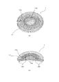
- (A) is a perspective view of an example of the lens plate for illumination lamps by this invention
- (b) is the fragmentary broken view of the lens plate. It is a perspective view of the other example of the lens plate for illumination lamps by this invention. It is a principle figure explaining refraction of light. It is a figure explaining the effect
- (A) is a perspective view of the other example of the lens plate for illumination lamps by this invention, (b) is the fragmentary broken view of the lens plate.
- an illumination lamp lens plate 1 is formed of a light-transmitting material such as acrylic or polycarbonate, and is attached to a light-emitting source 2 such as a light-emitting diode.
- interval is provided (FIG. 4).
- the light-transmitting material is basically assumed to be colorless and transparent, but may be one in which various colorants or diffusing agents such as titanium oxide are blended.
- the lens unit 11 has a basic shape obtained by cutting a part of a spherical surface having a predetermined thickness.
- a plurality of lens units 11 may be arranged in a common holding unit 13.
- the number of lens portions 11 is not particularly limited, and is determined according to the number of light emitting sources 2.
- the lens portion 11 is formed concentrically using the outer surface center portion and the inner surface peripheral edge portion so as not to overlap when the lens pattern 12 is viewed in a plan view.
- the inner surface is a surface on the side where light emitted from the light source 2 is incident
- the outer surface is a surface on the side where the light is emitted.
- the central axis of the lens unit 11 coincides with the central axis of the lens pattern 12
- the center of the lens unit 11 is the central axis of the lens pattern 12 when it is desired to irradiate light obliquely from the lens plate 1. It may be shifted from.
- the lens plate 1 does not have sufficient heat resistance, an appropriate distance is required between the light emitting source 2 and the lens unit 11, and as a result, the lens unit 11 is increased in size.
- the lens pattern 12 is formed using the outer surface central portion and the inner peripheral edge portion of the lens portion 11 as described above, the central portion of the lens pattern 12 is far from the light emitting source 2. Therefore, even if it is the small lens part 1, the front-end
- the lens unit 11 may be formed in a dome shape that protrudes to the outer surface side, and the central part thereof may be kept away from the light emitting source 2.
- This lens plate 1 is mainly intended for use in a spotlight or downlight, and is intended to narrow the spread of light emitted from the light source 2 by a condensing function. For this reason, the central portion of the lens pattern 12 refracts light from the light source 2 in the central axis direction, while the peripheral portion of the lens pattern 12 reflects the light from the light source 2 in the central axis direction. .
- a circular convex surface is arranged at the center of the lens pattern 12, and ridges having steep inner slopes and loose outer slopes are arranged concentrically around the circumference.
- the circular convex surface and the outer slope with a loose ridge form a refraction region 12a that refracts light from the light source 2 in the central axis direction.
- ridges each having a steep inner slope and an outer slope are arranged in multiple concentric circles.
- the steep outer slope of the ridge serves as a reflection region 12b that reflects light from the light source 2 in the direction of the central axis.
- the lens pattern 12 including the refraction area 12a and the reflection area 12b is a kind of Fresnel lens.
- the lens pattern 12 is composed of a circular convex surface and a plurality of protrusions, and a curved surface that causes refraction or total reflection is adjusted as appropriate, so that the refracted light and reflected light from these curved surfaces overlap. An effect is produced. Due to this effect, uneven color of the illumination light can be suppressed. A unique texture can be obtained by the lens pattern 12 exposed at the center of the outer surface of the lens unit 11. Moreover, since the circular convex surface and protrusion which comprise the refraction
- a refractive region 12 a is formed at the center of the outer surface of the lens unit 11, and a reflective region 12 b is formed at the inner periphery of the lens unit 11.
- a deformation such that the refraction area 12a protrudes to the inner peripheral edge of the lens and the reflection area 12b becomes narrow by that amount, or vice versa.
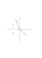
- FIG. 4 shows the traveling direction of incident light and reflected light in the longitudinal section of the lens unit 11 by arrows.
- the portion surrounded by the broken line (A) is the center of the lens pattern 12.
- incident light from the light source 2 travels straight on the central axis and passes through the lens unit 11 as it is.
- the portion surrounded by the broken line (B) is the refraction region 12a.
- incident light is refracted in the central axis direction on the inner surface of the lens unit 11, and further refracted in the central axis direction on the outer surface of the lens unit 11 and passes through the lens unit 11.
- Refraction at the inner and outer surfaces of the lens unit 11 satisfies the relationship of the above formula (1).
- the part surrounded by the broken line (C) is the reflection region 12b.
- incident light is refracted by the inner slope of the ridge formed on the inner surface of the lens portion 11, totally reflected by the outer slope of the ridge, and further refracted by the outer surface of the lens portion 11. Pass through.
- the refraction on the inner slope of the ridge and the outer surface of the lens portion 11 satisfies the relationship of the above formula (1), but the incident angle with respect to these interfaces is not so large.
- Total reflection from the outer slope plays an important role. This total reflection occurs under the condition that the above formula (1) cannot be established.
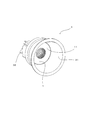
- FIG. 5 shows an appearance of an example of the illumination lamp 3 using the lens plate 1 as described above.
- the illumination lamp 3 is a spotlight, and the lens plate 1 is fitted in the back of a cylindrical light shielding hood portion 31.
- a heat radiating device 32 is attached behind the light emitting source 2.
- the central portion of the inner surface and the outer peripheral edge of the lens portion 11 where the lens pattern 12 is not formed are smooth surfaces.
- the diffusion region 12c is provided in the outer peripheral edge portion or the inner central portion of the lens portion 11 where the lens pattern 12 is not formed, color unevenness when the light emitting source 2 is a white light emitting diode can be further suppressed.
- the diffusion region 12c is formed by facet processing.
- the diffusion region 12 c surrounds the refractive region 12 a at the center of the outer surface of the lens unit 11. That is, a minute convex surface (facet) is stretched around the entire outer peripheral edge of the lens unit 11 in a tile shape. Even if these convex surfaces are replaced with concave surfaces, the same effect can be obtained.
- the diffusion region 12c can be formed by frost processing, or can be formed by a film containing a diffusing agent.
Landscapes
- Engineering & Computer Science (AREA)
- General Engineering & Computer Science (AREA)
- Physics & Mathematics (AREA)
- Mechanical Engineering (AREA)
- General Physics & Mathematics (AREA)
- Optics & Photonics (AREA)
- Non-Portable Lighting Devices Or Systems Thereof (AREA)
- Securing Globes, Refractors, Reflectors Or The Like (AREA)
Priority Applications (5)
| Application Number | Priority Date | Filing Date | Title |
|---|---|---|---|
| EP12873159.3A EP2833055A4 (de) | 2012-03-26 | 2012-07-19 | Linsenplatte für eine beleuchtungslampe und beleuchtungslampe |
| CN201280068521.XA CN104145157A (zh) | 2012-03-26 | 2012-07-19 | 照明灯用透镜板以及照明灯 |
| US14/378,939 US9534761B2 (en) | 2012-03-26 | 2012-07-19 | Lens plate for illumination lamp, and illumination lamp |
| PH12014501768A PH12014501768A1 (en) | 2012-03-26 | 2014-08-06 | Lens plate for illumination lamp, and illumination lamp |
| IN1667MUN2014 IN2014MN01667A (de) | 2012-03-26 | 2014-08-19 |
Applications Claiming Priority (2)
| Application Number | Priority Date | Filing Date | Title |
|---|---|---|---|
| JP2012069871A JP5980534B2 (ja) | 2012-03-26 | 2012-03-26 | 照明ランプ用レンズ板および照明ランプ |
| JP2012-069871 | 2012-03-26 |
Publications (1)
| Publication Number | Publication Date |
|---|---|
| WO2013145351A1 true WO2013145351A1 (ja) | 2013-10-03 |
Family
ID=49258701
Family Applications (1)
| Application Number | Title | Priority Date | Filing Date |
|---|---|---|---|
| PCT/JP2012/068308 Ceased WO2013145351A1 (ja) | 2012-03-26 | 2012-07-19 | 照明ランプ用レンズ板および照明ランプ |
Country Status (7)
| Country | Link |
|---|---|
| US (1) | US9534761B2 (de) |
| EP (1) | EP2833055A4 (de) |
| JP (1) | JP5980534B2 (de) |
| CN (1) | CN104145157A (de) |
| IN (1) | IN2014MN01667A (de) |
| PH (1) | PH12014501768A1 (de) |
| WO (1) | WO2013145351A1 (de) |
Cited By (1)
| Publication number | Priority date | Publication date | Assignee | Title |
|---|---|---|---|---|
| WO2024176633A1 (ja) * | 2023-02-20 | 2024-08-29 | 株式会社ミツバ | 車両用燈体 |
Families Citing this family (9)
| Publication number | Priority date | Publication date | Assignee | Title |
|---|---|---|---|---|
| US9175832B2 (en) * | 2013-09-16 | 2015-11-03 | Light Engine Limited | Faceted LED street lamp lens |
| JP6217972B2 (ja) * | 2013-11-05 | 2017-10-25 | パナソニックIpマネジメント株式会社 | 照明器具 |
| JP6094623B2 (ja) * | 2015-05-18 | 2017-03-15 | 株式会社遠藤照明 | 照明器具用フレネルレンズおよびそれを有する照明器具 |
| DE102016109647B4 (de) * | 2016-05-25 | 2022-08-25 | OSRAM Opto Semiconductors Gesellschaft mit beschränkter Haftung | Linse und Leuchte mit einer solchen Linse |
| JP7064762B2 (ja) * | 2018-06-23 | 2022-05-11 | アイリスオーヤマ株式会社 | 照明装置及び光学部材 |
| USD901752S1 (en) | 2019-01-25 | 2020-11-10 | Eaton Intelligent Power Limited | Optical structure |
| US11236887B2 (en) | 2019-01-25 | 2022-02-01 | Eaton Intelligent Power Limited | Optical structures for light emitting diodes (LEDs) |
| USD903187S1 (en) | 2019-01-25 | 2020-11-24 | Eaton Intelligent Power Limited | Optical structure |
| CN113791466B (zh) * | 2021-11-10 | 2022-03-01 | 中国空气动力研究与发展中心低速空气动力研究所 | 一种波浪形菲涅尔透镜及其制备方法 |
Citations (8)
| Publication number | Priority date | Publication date | Assignee | Title |
|---|---|---|---|---|
| JPS598201A (ja) * | 1982-07-05 | 1984-01-17 | 株式会社小糸製作所 | 車輌用灯具 |
| JP2005049367A (ja) * | 2003-07-29 | 2005-02-24 | Citizen Electronics Co Ltd | フレネルレンズおよび照明装置 |
| JP2007157542A (ja) * | 2005-12-06 | 2007-06-21 | Stanley Electric Co Ltd | 照明灯器 |
| JP2007212771A (ja) | 2006-02-09 | 2007-08-23 | Taika:Kk | フレネルレンズ、その製造方法及びその用途 |
| JP2008084696A (ja) | 2006-09-27 | 2008-04-10 | Toshiba Corp | 照明用レンズ及び照明装置 |
| JP2008181717A (ja) * | 2007-01-23 | 2008-08-07 | Koito Mfg Co Ltd | 車両用灯具ユニット |
| JP2010212089A (ja) * | 2009-03-10 | 2010-09-24 | Koito Mfg Co Ltd | 車両用灯具 |
| JP2010251013A (ja) * | 2009-04-13 | 2010-11-04 | Stanley Electric Co Ltd | 灯具 |
Family Cites Families (10)
| Publication number | Priority date | Publication date | Assignee | Title |
|---|---|---|---|---|
| US5128848A (en) * | 1989-03-31 | 1992-07-07 | W.C. Heraeus Gmbh | Operating light |
| GB9108033D0 (en) | 1991-04-16 | 1991-06-05 | Britax Vega Ltd | Vehicle lamp |
| US20050286145A1 (en) | 2004-06-25 | 2005-12-29 | Swarco Futurit Verkehrssignalsysteme Ges.M.B.H. | Invention concerning a condensor lens |
| JP2006054092A (ja) * | 2004-08-11 | 2006-02-23 | Koito Mfg Co Ltd | 車両用標識灯 |
| US7733580B2 (en) * | 2006-11-06 | 2010-06-08 | Panasonic Corporation | Light emitting module and light receiving module |
| TWI322867B (en) * | 2007-04-10 | 2010-04-01 | Ind Tech Res Inst | Improved lamp fixture |
| DE102008060969A1 (de) * | 2008-12-08 | 2010-06-10 | Osram Gesellschaft mit beschränkter Haftung | Streuscheibe |
| EP2287641B1 (de) * | 2009-08-21 | 2013-07-24 | Mass Technology (H.K.) Ltd. | Fresnellinsenfolie und Leuchte damit |
| EP2418415B1 (de) * | 2009-11-06 | 2014-10-15 | Panasonic Corporation | Punktlichtquelle und birnenartige lichtquelle |
| JP5528287B2 (ja) * | 2010-05-18 | 2014-06-25 | 株式会社エンプラス | 光束制御部材、発光装置、及び照明装置 |
-
2012
- 2012-03-26 JP JP2012069871A patent/JP5980534B2/ja active Active
- 2012-07-19 WO PCT/JP2012/068308 patent/WO2013145351A1/ja not_active Ceased
- 2012-07-19 US US14/378,939 patent/US9534761B2/en not_active Expired - Fee Related
- 2012-07-19 CN CN201280068521.XA patent/CN104145157A/zh active Pending
- 2012-07-19 EP EP12873159.3A patent/EP2833055A4/de not_active Withdrawn
-
2014
- 2014-08-06 PH PH12014501768A patent/PH12014501768A1/en unknown
- 2014-08-19 IN IN1667MUN2014 patent/IN2014MN01667A/en unknown
Patent Citations (8)
| Publication number | Priority date | Publication date | Assignee | Title |
|---|---|---|---|---|
| JPS598201A (ja) * | 1982-07-05 | 1984-01-17 | 株式会社小糸製作所 | 車輌用灯具 |
| JP2005049367A (ja) * | 2003-07-29 | 2005-02-24 | Citizen Electronics Co Ltd | フレネルレンズおよび照明装置 |
| JP2007157542A (ja) * | 2005-12-06 | 2007-06-21 | Stanley Electric Co Ltd | 照明灯器 |
| JP2007212771A (ja) | 2006-02-09 | 2007-08-23 | Taika:Kk | フレネルレンズ、その製造方法及びその用途 |
| JP2008084696A (ja) | 2006-09-27 | 2008-04-10 | Toshiba Corp | 照明用レンズ及び照明装置 |
| JP2008181717A (ja) * | 2007-01-23 | 2008-08-07 | Koito Mfg Co Ltd | 車両用灯具ユニット |
| JP2010212089A (ja) * | 2009-03-10 | 2010-09-24 | Koito Mfg Co Ltd | 車両用灯具 |
| JP2010251013A (ja) * | 2009-04-13 | 2010-11-04 | Stanley Electric Co Ltd | 灯具 |
Non-Patent Citations (1)
| Title |
|---|
| See also references of EP2833055A4 |
Cited By (2)
| Publication number | Priority date | Publication date | Assignee | Title |
|---|---|---|---|---|
| WO2024176633A1 (ja) * | 2023-02-20 | 2024-08-29 | 株式会社ミツバ | 車両用燈体 |
| JP2024117963A (ja) * | 2023-02-20 | 2024-08-30 | 株式会社ミツバ | 車両用燈体 |
Also Published As
| Publication number | Publication date |
|---|---|
| CN104145157A (zh) | 2014-11-12 |
| JP2013201075A (ja) | 2013-10-03 |
| IN2014MN01667A (de) | 2015-05-29 |
| US9534761B2 (en) | 2017-01-03 |
| EP2833055A4 (de) | 2015-10-14 |
| US20150009683A1 (en) | 2015-01-08 |
| EP2833055A1 (de) | 2015-02-04 |
| JP5980534B2 (ja) | 2016-08-31 |
| PH12014501768B1 (en) | 2014-11-17 |
| PH12014501768A1 (en) | 2014-11-17 |
Similar Documents
| Publication | Publication Date | Title |
|---|---|---|
| JP5980534B2 (ja) | 照明ランプ用レンズ板および照明ランプ | |
| TWI326752B (de) | ||
| US9442241B2 (en) | Optics for illumination devices | |
| US20140016326A1 (en) | Asymmetric area lighting lens | |
| JP4970172B2 (ja) | 照明器具 | |
| KR20140109137A (ko) | 원형 라이트 가이드 및 이를 포함하는 차량용 램프 | |
| JP6507035B2 (ja) | 光束制御部材、発光装置および照明装置 | |
| JP2014103062A (ja) | 照明装置 | |
| WO2013179610A1 (ja) | 光束制御部材、発光装置および照明装置 | |
| JP5668920B2 (ja) | 照明装置 | |
| US20180246305A1 (en) | Lighting device with virtual light source | |
| JP5977636B2 (ja) | 光束制御部材、発光装置および照明装置 | |
| US20110141731A1 (en) | Reflection-type light-emitting assembly | |
| JP2012209049A (ja) | Led照明装置およびレンズ | |
| WO2016009798A1 (ja) | 光束制御部材、発光装置および照明装置 | |
| JP3197828U (ja) | 均一照度を有する灯具 | |
| JP6326455B2 (ja) | 照明ランプ | |
| JP2017168335A (ja) | 車両用灯具 | |
| JP6386808B2 (ja) | 照明装置 | |
| JP2012123984A (ja) | 照明装置 | |
| TWI386597B (zh) | 光學透鏡及包含該光學透鏡之照明裝置 | |
| CN108916805B (zh) | 车灯透镜 | |
| CN203892938U (zh) | 大角度球泡灯 | |
| JP2014007135A (ja) | 照明装置 | |
| KR101742196B1 (ko) | Led 소자용 광확산 렌즈 |
Legal Events
| Date | Code | Title | Description |
|---|---|---|---|
| 121 | Ep: the epo has been informed by wipo that ep was designated in this application |
Ref document number: 12873159 Country of ref document: EP Kind code of ref document: A1 |
|
| WWE | Wipo information: entry into national phase |
Ref document number: 12014501768 Country of ref document: PH |
|
| WWE | Wipo information: entry into national phase |
Ref document number: 14378939 Country of ref document: US |
|
| REEP | Request for entry into the european phase |
Ref document number: 2012873159 Country of ref document: EP |
|
| WWE | Wipo information: entry into national phase |
Ref document number: 2012873159 Country of ref document: EP |
|
| WWE | Wipo information: entry into national phase |
Ref document number: IDP00201405863 Country of ref document: ID |
|
| NENP | Non-entry into the national phase |
Ref country code: DE |