WO2013145357A1 - Dispositif vibrant et terminal mobile l'utilisant - Google Patents
Dispositif vibrant et terminal mobile l'utilisant Download PDFInfo
- Publication number
- WO2013145357A1 WO2013145357A1 PCT/JP2012/069416 JP2012069416W WO2013145357A1 WO 2013145357 A1 WO2013145357 A1 WO 2013145357A1 JP 2012069416 W JP2012069416 W JP 2012069416W WO 2013145357 A1 WO2013145357 A1 WO 2013145357A1
- Authority
- WO
- WIPO (PCT)
- Prior art keywords
- vibration
- diaphragm
- amplitude
- vibration element
- vibration device
- Prior art date
- Legal status (The legal status is an assumption and is not a legal conclusion. Google has not performed a legal analysis and makes no representation as to the accuracy of the status listed.)
- Ceased
Links
Images






Classifications
-
- H—ELECTRICITY
- H10—SEMICONDUCTOR DEVICES; ELECTRIC SOLID-STATE DEVICES NOT OTHERWISE PROVIDED FOR
- H10N—ELECTRIC SOLID-STATE DEVICES NOT OTHERWISE PROVIDED FOR
- H10N30/00—Piezoelectric or electrostrictive devices
- H10N30/20—Piezoelectric or electrostrictive devices with electrical input and mechanical output, e.g. functioning as actuators or vibrators
- H10N30/204—Piezoelectric or electrostrictive devices with electrical input and mechanical output, e.g. functioning as actuators or vibrators using bending displacement, e.g. unimorph, bimorph or multimorph cantilever or membrane benders
-
- H—ELECTRICITY
- H04—ELECTRIC COMMUNICATION TECHNIQUE
- H04R—LOUDSPEAKERS, MICROPHONES, GRAMOPHONE PICK-UPS OR LIKE ACOUSTIC ELECTROMECHANICAL TRANSDUCERS; ELECTRIC HEARING AIDS; PUBLIC ADDRESS SYSTEMS
- H04R17/00—Piezoelectric transducers; Electrostrictive transducers
-
- H—ELECTRICITY
- H04—ELECTRIC COMMUNICATION TECHNIQUE
- H04R—LOUDSPEAKERS, MICROPHONES, GRAMOPHONE PICK-UPS OR LIKE ACOUSTIC ELECTROMECHANICAL TRANSDUCERS; ELECTRIC HEARING AIDS; PUBLIC ADDRESS SYSTEMS
- H04R7/00—Diaphragms for electromechanical transducers; Cones
- H04R7/02—Diaphragms for electromechanical transducers; Cones characterised by the construction
- H04R7/04—Plane diaphragms
- H04R7/045—Plane diaphragms using the distributed mode principle, i.e. whereby the acoustic radiation is emanated from uniformly distributed free bending wave vibration induced in a stiff panel and not from pistonic motion
-
- H—ELECTRICITY
- H10—SEMICONDUCTOR DEVICES; ELECTRIC SOLID-STATE DEVICES NOT OTHERWISE PROVIDED FOR
- H10N—ELECTRIC SOLID-STATE DEVICES NOT OTHERWISE PROVIDED FOR
- H10N30/00—Piezoelectric or electrostrictive devices
- H10N30/80—Constructional details
- H10N30/88—Mounts; Supports; Enclosures; Casings
-
- H—ELECTRICITY
- H04—ELECTRIC COMMUNICATION TECHNIQUE
- H04R—LOUDSPEAKERS, MICROPHONES, GRAMOPHONE PICK-UPS OR LIKE ACOUSTIC ELECTROMECHANICAL TRANSDUCERS; ELECTRIC HEARING AIDS; PUBLIC ADDRESS SYSTEMS
- H04R2499/00—Aspects covered by H04R or H04S not otherwise provided for in their subgroups
- H04R2499/10—General applications
- H04R2499/11—Transducers incorporated or for use in hand-held devices, e.g. mobile phones, PDA's, camera's
Definitions
- the present invention relates to a vibration device and a portable terminal using the vibration device.
- the above-described conventional vibration device needs to have a sufficient space between the vibration element and the vibration plate so that the vibration element and the vibration plate do not come into contact with each other when an impact is applied. There was a problem that it was difficult.
- the vibration of the vibration plate becomes weak depending on the position where the vibration element is attached. This has been clarified by the inventors' investigation.
- the present invention has been devised in view of such problems, and an object of the present invention is to provide a vibration device capable of reducing the thickness and generating strong vibrations and a portable terminal using the vibration device. .
- the vibration device of the present invention is supported by a support, a peripheral edge joined to the support, a first part joined to the support, and the support located inside the first part.
- a diaphragm having a second part that is not joined, and a surface on one side in the first direction are joined to the second part of one main surface of the diaphragm, and an electric signal is input
- An interval between the vibration element and the first portion in a third direction perpendicular to the first direction is a first interval
- an interval between the vibration element and the first portion in the second direction is a second interval. Then, the first interval is larger than the second interval. It is an.
- the portable terminal of the present invention includes at least the vibration device and an electronic circuit that generates an electric signal input to the vibration element.
- the vibration device of the present invention it is possible to obtain a vibration device that can be thinned and can generate strong vibration.
- the portable terminal of the present invention it is possible to obtain a portable terminal that can be thinned and can clearly transmit voice information.
- FIG. 2 is a cross-sectional view taken along line A-A ′ in FIG. 1.
- FIG. 2 is a cross-sectional view taken along line B-B ′ in FIG. 1.
- It is a top view which shows typically the state which saw through the support body of the vibration apparatus shown in FIG.
- It is a perspective view which shows typically the vibration element in the vibration apparatus shown in FIG. (A)-(e) is a top view for demonstrating the structure of the vibration element shown in FIG.
- FIG. (A)-(e) is a top view for demonstrating the structure of the vibration element shown in FIG.
- FIG. is a figure for demonstrating the structure of the vibration element shown in FIG.
- FIG. is a perspective view which shows typically the portable terminal of the 2nd example of embodiment of this invention.
- FIG. 9 is a sectional view taken along line C-C ′ in FIG. 8.
- FIG. 9 is a sectional view taken along line D-D ′ in FIG. 8. It is a graph which shows the sound pressure of the sound produced
- FIG. 1 is a perspective view schematically showing a vibration device of a first example of an embodiment of the present invention.
- 2 is a cross-sectional view taken along line AA ′ in FIG. 3 is a cross-sectional view taken along the line BB ′ in FIG.
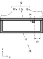
- FIG. 4 is a plan view schematically showing a state seen through the support 11 of the vibration device 15 shown in FIG. FIG. 4 shows a state viewed from the ⁇ z direction side. 2 to 4, the detailed structure of the vibration element 14 is not shown in order to facilitate drawing.
- the first direction (the z-axis direction in the figure) is the thickness direction
- the second direction perpendicular to the first direction is the width direction
- the first direction and the third direction (y-axis direction in the figure) perpendicular to the second direction are rectangular parallelepiped shapes.
- the vibration device 15 of this example includes a support 11, a vibration plate 12, and a vibration element 14.
- the support 11 has a box shape with one surface opened.
- the support 11 can be preferably formed using a material such as a synthetic resin having high rigidity and elasticity, but may be formed using another material such as a metal.
- the support 11 may have a shape other than a box shape, for example, a frame shape. Further, the support 11 need not be a single object.
- the support 11 may be composed of a plurality of objects.
- the diaphragm 12 has a rectangular thin plate shape, and the first direction (z-axis direction in the figure) is the thickness direction, and the second direction (x-axis direction in the figure) is the width direction. The third direction (the y-axis direction in the figure) is the length direction. Further, the diaphragm 12 is supported by supporting the peripheral edge of one main surface (the main surface on the ⁇ z direction side in the drawing) to the support 11, the first portion 12 a bonded to the support 11, It has the 2nd part 12b which is located inside the 1 part 12a and is not joined to the support body 11.
- the diaphragm 12 can be formed preferably using a material having high rigidity and elasticity such as acrylic resin or glass.
- the thickness of the diaphragm 12 is set to about 0.4 mm to 1.5 mm, for example.
- various existing adhesives can be used for joining the support 11 and the diaphragm 12.
- the vibration element 14 has a rectangular parallelepiped shape, the first direction (z-axis direction in the figure) is the thickness direction, and the second direction (x-axis direction in the figure) is the length direction,
- the third direction (the y-axis direction in the figure) is the width direction. That is, the vibration element 14 is arranged so that the length direction of the vibration element 14 matches the width direction of the vibration plate 12 and the width direction of the vibration element 14 matches the length direction of the vibration plate 12.
- the vibration element 14 has a surface on one side in the first direction (+ z direction side in the figure) joined to a second portion 12b of one main surface of the vibration plate 12 (main surface on the ⁇ z direction side in the figure). ing.
- the vibration element 14 is bonded to a position in the second portion 12b that is centered in the second direction (x-axis direction in the figure) and biased to one side in the third direction (+ y direction side in the figure). Has been.
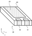
- FIG. 5 is a perspective view schematically showing the vibration element 14.
- FIGS. 6A to 6E are plan views schematically showing the shapes of the electrodes 21 to 25 included in the vibration element 14.
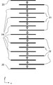
- FIG. 7 is a diagram schematically showing the positional relationship of the electrodes 21 to 25 in the first direction (the z-axis direction in the drawing) and the polarization state of the piezoelectric layer 27 disposed between the electrodes 21 to 25. It is.
- FIGS. 6A to 6D show a state viewed from one side in the first direction (+ z direction side in the figure), and FIG. 6E shows the other side in the first direction. It shows a state viewed from (the ⁇ z direction side in the figure).
- the laminated body 20, the first to third terminal electrodes, and the piezoelectric layer 27 are not shown.
- the vibration element 14 includes the stacked body 20, a first terminal electrode 41, a second terminal electrode 42, and a third terminal electrode (not shown).
- the first terminal electrode 41 and the first terminal electrode 41 and the second end of the stacked body 20 are disposed on one end face (+ x direction side in the figure) in the second direction so as to straddle both end faces in the first direction (z axis direction in the figure).
- Two terminal electrodes 42 are arranged.
- a third terminal electrode (not shown) is disposed on the end surface of the other side of the stacked body 20 in the second direction ( ⁇ x direction side in the figure).
- the laminated body 20 includes a plurality of piezoelectric layers 27 polarized in a first direction (z-axis direction in the figure) and a plurality of flat electrodes 21 to 25 alternately along the first direction. Arranged and configured.
- the electrode 23 is disposed on the surface of one side (the + z direction side in the drawing) of the stacked body 20 in the first direction.
- the electrode 25 is disposed on the surface of the stacked body 20 on the other side in the first direction (the ⁇ z direction side in the drawing).
- a plurality of electrodes 21, electrodes 22, and electrodes 24 are arranged inside the stacked body 20.
- the electrode 21 or the electrode 22 and the electrode 23 or the electrode 24 or the electrode 25 are alternately arrange
- the electrode 21 has a structure in which one end of a rectangular lead portion 21b is connected to one end of a rectangular main body portion 21a formed at a distance from the side surface of the laminate 20. The other end of the lead portion 21 b is connected to the first terminal electrode 41.
- the electrode 22 has a structure in which one end of a rectangular lead portion 22b is connected to one end of a rectangular main body portion 22a formed at a distance from the side surface of the laminate 20. The other end of the lead portion 22 b is connected to the second terminal electrode 42.
- Each of the electrodes 23, 24, 25 has a rectangular shape in which only one end in the length direction is exposed on the side surface of the stacked body 20. One end in the length direction of each of the electrodes 23, 24, and 25 is connected to a third terminal electrode (not shown).
- the piezoelectric layer 27 disposed between the electrodes 21 to 25 is polarized in a direction indicated by an arrow in FIG. That is, one side of the first direction (+ z direction side in the figure) is polarized in the direction from the electrode 21 to the electrodes 23 and 24, and the other side of the first direction ( ⁇ z direction side in the figure).
- the electrodes 24 and 25 are polarized in the direction from the electrodes 22.
- the electrodes 21 and 22 are at the same potential
- the electrodes 23, 24, and 25 are at the same potential
- An AC voltage is applied so that a potential difference is generated.
- the vibration element 14 is configured such that the polarization direction with respect to the direction of the electric field applied at a certain moment is reversed between one side and the other side in the first direction (z-axis direction in the drawing).
- the vibration element 14 bends and vibrates in the first direction so that the amplitude changes along the second direction perpendicular to the first direction when the electric signal is input.
- the vibration element 14 is a piezoelectric vibration element including a piezoelectric body (piezoelectric bimorph element) having a bimorph structure.
- the laminate 20 can have a length of about 18 mm to 28 mm, a width of about 1 mm to 6 mm, and a thickness of about 0.2 mm to 1.0 mm, for example.
- the length of the electrodes 21 to 25 can be set to, for example, about 17 mm to 25 mm, and the width of the electrodes 21 to 25 can be set to, for example, about 0.5 mm to 1.5 mm.
- the piezoelectric layer 27 constituting the laminate 20 is preferably made of, for example, lead-free piezoelectric material such as lead titanate (PT), lead zirconate titanate (PZT), Bi layered compound, tungsten bronze structure compound, or the like. However, other piezoelectric materials may be used.
- the thickness of one layer of the piezoelectric layer 27 can be set to about 0.01 to 0.1 mm, for example.
- the electrodes 21, 22, and 24 can be formed by suitably using, for example, a ceramic component or a glass component in addition to a metal component such as silver or an alloy of silver and palladium. You may form using a known metal material.
- the electrodes 23 and 25 and the first to third terminal electrodes preferably contain a metal component made of silver and a glass component, but may be a metal other than silver.
- Such a vibration element 14 can be manufactured by the following method, for example. First, a binder, a dispersant, a plasticizer, and a solvent are added to the piezoelectric material powder, and the mixture is agitated to produce a slurry. The obtained slurry is formed into a sheet shape to produce a green sheet. Next, a conductive paste is printed on the green sheet to form electrode patterns to be the electrodes 21, 22, and 24. The green sheets on which the electrode patterns are formed are stacked and pressed using a press device to form a laminated molded body Is made. Then, degreasing and baking are performed, and a laminated body is obtained by cutting to a predetermined dimension.
- the piezoelectric layer 27 is polarized by applying a DC voltage through the first to third terminal electrodes.
- various existing adhesives can be used for joining the vibration element 14 and the diaphragm 12.
- a protective layer made of a piezoelectric body or the like may be provided. In that case, it is desirable to sufficiently reduce the thickness of the protective layer.
- the vibration device 15 of this example having such a configuration functions as a vibration device that vibrates the diaphragm 12 by bending vibration of the vibration element 14 by applying an electric signal.
- the surface of the vibration element 14 on one side in the first direction is the one main surface of the vibration plate 12 (the main surface on the ⁇ z direction side in the drawing). It is joined to the second portion 12b. Therefore, the vibration device 15 of this example can be thinned. Further, in the vibration device 15 of this example, since the vibration element 14 has a long shape in the second direction (x-axis direction in the figure), the vibration vibration in the second direction is efficiently applied to the diaphragm 12. Can be generated.
- the distance between the vibration element 14 and the first portion 12a in the third direction is the first distance d1
- the second direction is the x-axis in the figure.
- the first distance d1 is larger than the second distance d2.
- the vibration apparatus 15 of this example can vibrate the diaphragm 12 strongly.
- a relationship of d1 / d2 ⁇ 1.5 is established between the first interval d1 and the second interval d2. Thereby, the vibration device 15 of this example can vibrate the diaphragm 12 more strongly.
- the interval d1 is set as follows.
- the first distance d1 is the minimum value of the distance between the vibration element 14 and the first portion 12a in the third direction
- the second distance d2 is the vibration element 14 and the first portion in the second direction.
- 12a is the minimum value of the interval.
- the inventor causes excessive vibration of the vibration plate 12 if the vibration element 14 is too close to the first portion 12a. It turned out to be weak. Further, the first interval d1 is particularly important for strongly vibrating the diaphragm 12. In order to vibrate the diaphragm 12 strongly, the first interval d1 is at least larger than the second interval d2. I found it necessary.
- the vibration element 14 is arranged at the center in the third direction (y-axis direction in the drawing) of the second portion 12b by setting the first distance d1 to be 1.5 times the second distance d2 or more.
- the diaphragm 12 can be vibrated strongly as much as. If the second distance d2 is too small, the vibration of the diaphragm 12 becomes weak. Therefore, the second distance d2 is 0 in the length of the vibration element 14 in the second direction (x-axis direction in the drawing). It is desirable to set it to 3 times or more.
- the vibration element 14 and the vibration plate 12 are arranged so that the length directions thereof are orthogonal to each other, the vibration of the vibration plate 12 is prevented from being weakened while vibrating.
- the element 14 can be disposed at the peripheral portion of the diaphragm 12 and the vibration of the diaphragm 12 can be reduced from rapidly increasing at a specific frequency.
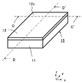
- FIG. 8 is a perspective view schematically showing a mobile terminal according to a second example of the embodiment of the present invention.
- 9 is a cross-sectional view taken along the line CC ′ in FIG. 10 is a cross-sectional view taken along the line DD ′ in FIG. 9 and 10, the detailed structure of the vibration element 14 is not shown.
- the same referential mark is attached
- the portable terminal of this example includes the vibration device 15, the electronic circuit 17, and the display 18 of the first example of the above-described embodiment.
- the electronic circuit 17 generates an electric signal input to the vibration element 14.
- the electrical signal includes audio information.
- the electronic circuit 17 may include other circuits such as a circuit for processing image information to be displayed on the display 18 and a communication circuit.
- the electronic circuit 17 and the vibration element 14 are connected via a wiring (not shown).
- the display 18 is a display device having a function of displaying image information.
- a known display such as a liquid crystal display, a plasma display, and an organic EL display can be suitably used.
- the display 18 may have an input device such as a touch panel.
- the diaphragm 12 is disposed outside the display 18 and integrated with the display 18, and functions as a cover for protecting the display 18.
- the diaphragm 12 may have an input device such as a touch panel.
- the portable terminal of this example having such a configuration can generate sound by vibrating the vibration plate 12 by vibrating the vibration element 14. And the sound information can be transmitted to a person by this sound. Moreover, you may transmit audio
- the portable terminal of this example transmits audio information using the vibration device 15 that is thin and capable of generating strong vibrations, it is possible to obtain a portable terminal that can be thinned and can clearly transmit audio information. Can do.
- the difference in amplitude depending on the position in the first surface 12c of the vibrating diaphragm 12 be 60 dB or less in the ratio of the maximum value to the minimum value. That is, the diaphragm 12 is vibrated by giving an electric signal having sound information to the vibration element 14, and the ear is brought close to the amplitude of the first surface 12 c of the diaphragm 12 and the first surface 12 c of the diaphragm 12.
- the ratio of the amplitude at which sound is too loud and painful to the minimum amplitude at which voice information can be acquired was 60 dB.
- the value of 60 dB coincides with the difference between 40 dB, which is a hearing ability for listening to a quiet conversation, and 100 dB, a hearing ability for listening to a screaming voice at the ear. Further, the amplitude of the first surface 12c of the diaphragm 12 and the sound pressure in the space close to the first surface 12c of the diaphragm 12 are in a proportional relationship.
- the difference in amplitude depending on the position in the first surface 12c of the vibrating diaphragm 12 is 60 dB or less in the ratio of the maximum value to the minimum value, so that the first surface 12c of the diaphragm 12 has a difference. Audio information can be acquired no matter which part is close to the ear. Therefore, according to the mobile terminal of this example, it is possible to obtain a mobile terminal that can obtain sound information satisfactorily by simply bringing it close to or in contact with the ear without particular attention.
- the difference in amplitude depending on the position in the first surface 12c of the vibrating diaphragm 12 is 20 dB or less as a ratio of the maximum value to the minimum value. That is, the diaphragm 12 is vibrated by giving an electric signal having sound information to the vibration element 14, and the ear is brought close to the amplitude of the first surface 12 c of the diaphragm 12 and the first surface 12 c of the diaphragm 12. As a result of comparison with the degree of hearing when the vibration is performed, the difference in amplitude depending on the position in the first surface 12c of the vibrating diaphragm 12 is set to 20 dB or less in the ratio of the maximum value to the minimum value.
- the hearing ability for listening to a quiet conversation is 40 dB
- the hearing ability for listening to a loud conversation is 80 dB. That is, there is a 40 dB level difference between a small voice and a loud voice in a conversation.
- the level difference between the small and loud voices in the conversation from 60 dB, which is the ratio of the amplitude that makes the sound too loud and painful to the minimum amplitude at which voice information can be acquired (listen to the conversation)
- Subtracting 40 dB is 20 dB.
- the first of the diaphragm 12 It can be seen that, regardless of which part of the first surface 12c is close to the ear, it is possible to satisfactorily listen from a conversation with a low voice to a conversation with a loud voice.
- the periphery of the diaphragm 12 may be firmly joined to the support 11. Thereby, although the amplitude of the diaphragm 12 becomes small, the difference of the amplitude by the position in the 1st surface 12c can be made small.
- the elastic modulus of a member such as an adhesive
- the area of the first portion 12a joined to the support 11 may be increased.
- the portable terminal of this example has a case where a weight of 10 N is applied to point A and a case where no weight is applied to point A, which is an arbitrary position in the first surface 12 c of the vibrating diaphragm 12. It is desirable that the difference in amplitude is 60 dB or less in the ratio of the amplitude when the weight is not applied when the weight of 10N is added. That is, as a result of measuring the weight applied to the portable terminal when the portable terminal is brought into contact with the ear during a call, it was about 10 N when pressed strongly.
- the difference in amplitude between the case where a weight of 10N is applied to point A and the case where no weight is applied is 10N.
- the difference in amplitude between the case where a weight of 10N is applied to point A and the case where no weight is applied is 10N.
- the ratio of the amplitude to the amplitude with no weight applied is 20 dB or less, so that it is possible to make a loud voice from a conversation with a small voice just by approaching or touching the ear without any particular attention. Can listen well to the conversation. That is, it is possible to obtain a portable terminal that can listen well from a conversation with a small voice to a conversation with a large voice, even if it is brought close to the ear, weakly touching the ear, or strongly touching the ear.
- the diaphragm 12 and the vibration element 14 are used. It is preferable to reduce the elastic modulus of the member to be joined. Further, since it is also effective to firmly bond the diaphragm 12 to the support body 11, it is effective to increase the elastic modulus of a member that joins the diaphragm 12 and the support body 11, and the diaphragm 12 and the support body 11 are supported. It is also possible to increase the bonding area with the body 11.
- the portable terminal of this example has an amplitude in the first surface 12c at an arbitrary position in the first surface 12c of the vibrating diaphragm 12 when the weight of 10N is applied to the position. It is desirable that the difference due to the position is 60 dB or less in the ratio of the maximum value to the minimum value. In other words, at an arbitrary location in the first surface 12c of the vibrating diaphragm 12, when the amplitude at that location when a weight of 10 N is applied to the location is measured, the vibration in the first surface 12c is measured. It is desirable that the difference due to the position is 60 dB or less in the ratio of the maximum value to the minimum value.
- the difference in the amplitude when a weight of 10 N is applied to an arbitrary position in the first surface 12c of the vibrating diaphragm 12 depending on the position in the first surface 12c is the minimum value. It is further desirable that the ratio of the maximum value to be 20 dB or less. Thereby, no matter which part of the first surface 12c of the diaphragm 12 is pressed against the ear, it is possible to listen well from a conversation with a small voice to a conversation with a loud voice.
- a change in amplitude in the micro area of the diaphragm 12 that does not affect the acquisition of audio information is not a problem.
- the problem is a macro amplitude change in the first surface 12c of the diaphragm 12 that affects the acquisition of audio information. Therefore, when measuring the amplitude, it is desirable to attach an acceleration sensor having a predetermined size to the first surface 12c of the diaphragm 12 and calculate the amplitude from the acceleration detected by the acceleration sensor.
- the frequency of human conversation is said to be about 500 Hz to 2 kHz.
- the vibration element 14 is arranged at the center in the second direction (x-axis direction in the drawing) of the second portion 12b has been described. Is not to be done.
- the vibration element 14 may be arranged at a position biased to one side in the second direction of the second portion 12b.
- the vibration element 14 has the 16 piezoelectric layers 27
- the number of piezoelectric layers 27 may be larger or smaller.
- the cover of the display 18 functions as the diaphragm 12
- the present invention is not limited to this.
- the display 18 itself may function as the diaphragm 12.
- the support 11 was an aluminum frame.
- the diaphragm 12 is a glass plate having a length of 96 mm, a width of 49 mm, and a thickness of 0.7 mm.
- the peripheral edge of the main surface on the other side in the first direction (the ⁇ z direction side in the figure) is 4 mm.
- the width was adhered and fixed to the support 11. That is, the 4 mm width portion on the periphery of the diaphragm 12 is the first portion 12 a, and the inner length 88 mm and the 41 mm width portion is the second portion 12 b.
- a double-sided tape having a thickness of 0.2 mm was used for adhesion between the diaphragm 12 and the support 11.
- the vibration element 14 had a rectangular parallelepiped shape with a length of 23.5 mm, a width of 3.3 mm, and a thickness of 0.5 mm.
- the vibration element 14 has a structure in which piezoelectric layers 27 having a thickness of about 30 ⁇ m and internal electrodes 21 to 25 are alternately stacked, and the total number of piezoelectric layers 27 is 16.
- the piezoelectric layer 27 was formed of lead zirconate titanate (PZT) in which a part of Zr was substituted with Sb.
- PZT lead zirconate titanate
- the vibration element 14 is positioned at the center of the second portion 12b in the second direction (the x-axis direction in the figure).
- d1 / d2 which is the ratio of the first interval d1 to the second interval d2 is changed
- d1 / d2 is Three examples of the vibration device 15 of the first embodiment of the present invention having 1.5, 2.6, and 4.8, and two comparative examples having d1 / d2 of 0.4 and 1.0, respectively.
- the sound pressure of the sound generated from the diaphragm 12 of the manufactured vibration device was measured.
- a microphone is installed at a position 10 mm away from the surface of the diaphragm 12 on one side in the first direction (+ z direction side in the figure), and a sine wave signal with a voltage of 30 Vp-p is applied to the vibration element 14.
- the sound pressure detected by the microphone was measured.
- the frequency of the sine wave signal input to the vibration element 14 was changed in three stages of 1 kHz, 1.5 kHz, and 2 kHz, and measurement was performed at each frequency.
- the horizontal axis indicates d1 / d2 which is the ratio of the first interval d1 to the second interval d2, and the vertical axis indicates the sound pressure.
- the measurement result when the frequency of the sine wave signal input to the vibration element 14 is 1 kHz is indicated by ⁇
- the measurement result when the frequency is 1.5 kHz is indicated by ⁇
- the measurement result when the frequency is 2 kHz. Is indicated by ⁇ .
- the vibration of the diaphragm 12 can be strengthened to generate sound with sufficient sound pressure.
- the diaphragm 12 was a glass plate having a length of 95 mm, a width of 48 mm, and a thickness of 0.7 mm.
- the vibration element 14 was a rectangular parallelepiped shape having a length of 25.0 mm, a width of 4.0 mm, and a thickness of 0.75 mm.
- the vibration element 14 has a structure in which piezoelectric layers and electrode layers having a thickness of about 30 ⁇ m are alternately stacked, and the total number of piezoelectric layers is 24.
- the piezoelectric layer was formed of lead zirconate titanate (PZT) in which part of Zr was replaced with Sb.
- PZT lead zirconate titanate
- a double-sided tape having a thickness of 0.16 mm in which an acrylic pressure-sensitive adhesive is applied to both surfaces of a non-woven fabric base material is used. Affixed to the entire surface.
- a double-sided tape having a thickness of 0.15 mm, in which an acrylic adhesive is applied to both surfaces of a nonwoven fabric base is opposite to the first face 12 c of the diaphragm 12. The entire periphery of the side surface was bonded to the support 11.
- the support 11 was made of synthetic resin.
- an electric signal was input to the vibration element 14 and the amplitude in each part in the first surface 12c of the diaphragm 12 was measured.
- an acceleration sensor was installed at a measurement point in the first surface 12c, and the amplitude was calculated from the measured value of acceleration at that position.
- the amplitude was measured in the same manner in a state where a pressure of 10 N was applied by pressing from above the acceleration sensor.
- the electric signal input to the vibration element 14 is a sine wave of 30 Vpp at 1 kHz, and a signal generated by a synthesized function generator (FG110 manufactured by Yokogawa Meter & Instruments Co., Ltd.) It was generated by amplification with POP120-2.5) manufactured by Co., Ltd.
- FG110 manufactured by Yokogawa Meter & Instruments Co., Ltd.
- POP120-2.5 POP120-2.5
- the acceleration sensor As the acceleration sensor, SV1109 manufactured by NEC Avio Infrared Technology Co., Ltd. was used, and the circular surface of the acceleration sensor having a diameter of 8 mm was attached to a predetermined position on the first surface 12c of the diaphragm 12 with an adhesive.
- the charge signal output from the acceleration sensor is converted into a voltage signal by a charge amplifier (AG2101 manufactured by NEC Avio Infrared Technology Co., Ltd.), and the voltage value is read using a digital oscilloscope (DL1540 manufactured by Yokogawa Electric).
- the acceleration was obtained using a conversion formula between the voltage value and acceleration attached to the charge amplifier.
- the load applied from the top of the acceleration sensor is measured using a load cell (C2G1-6K-A manufactured by Minebea Co., Ltd.), and the load value displayed on the digital peak holder (CSD-819C manufactured by Minebea Co., Ltd.) connected to the load cell. I read.
- the load cell was placed under the mobile terminal.
- the portable terminal is placed on a table installed on the load cell so that the first surface 12c of the diaphragm 12 is on the upper side, and the acceleration sensor is placed on the measurement point on the first surface 12c of the diaphragm 12.
- the acceleration sensor was placed on the measurement point on the first surface 12c of the diaphragm 12.
- the amplitude of the position having the smallest amplitude is 0.58 ⁇ m and the amplitude of the position having the largest amplitude is 2.98 ⁇ m on the first surface 12c.
- the ratio of the maximum amplitude 2.98 ⁇ m to the minimum amplitude 0.58 ⁇ m was 14.2 dB.
- the position where the amplitude is the largest on the first surface 12 c is the place where the vibration element 14 is attached to the opposite surface, and the position where the amplitude is the smallest on the first surface 12 c is the longitudinal direction of the diaphragm 12. In FIG. 5, the end portion is on the side opposite to the side on which the vibration element 14 is attached. This was the same even when the frequency of the electric signal input to the vibration element 14 was changed.
- the amplitude changed most greatly when no load was applied and when a load of 10N was applied, where the vibration element 14 was attached to the opposite surface.
- the ratio of the amplitude when the weight was not applied to the amplitude when the weight of 10N was added was 14.3 dB.
- the amplitude of the place where the amplitude is the smallest in the first surface 12c is 0.15 ⁇ m, and the amplitude is the largest in the first surface 12c.
- the location amplitude was 0.57 ⁇ m.
- the ratio of the maximum amplitude 0.57 ⁇ m to the minimum amplitude 0.15 ⁇ m was 11.6 dB.
Landscapes
- Engineering & Computer Science (AREA)
- Physics & Mathematics (AREA)
- Acoustics & Sound (AREA)
- Signal Processing (AREA)
- Multimedia (AREA)
- Piezo-Electric Transducers For Audible Bands (AREA)
- Telephone Set Structure (AREA)
- Diaphragms For Electromechanical Transducers (AREA)
- Details Of Audible-Bandwidth Transducers (AREA)
Abstract
Priority Applications (4)
| Application Number | Priority Date | Filing Date | Title |
|---|---|---|---|
| KR1020137010414A KR101487268B1 (ko) | 2012-03-30 | 2012-07-31 | 진동장치 및 그것을 사용한 휴대단말 |
| CN201280071596.3A CN104170406B (zh) | 2012-03-30 | 2012-07-31 | 振动装置以及使用该振动装置的便携式终端 |
| US13/993,440 US9219222B2 (en) | 2012-03-30 | 2012-07-31 | Vibration device and portable terminal employing the same |
| JP2012535511A JP5409926B1 (ja) | 2012-03-30 | 2012-07-31 | 振動装置およびそれを用いた携帯端末 |
Applications Claiming Priority (4)
| Application Number | Priority Date | Filing Date | Title |
|---|---|---|---|
| JP2012-080741 | 2012-03-30 | ||
| JP2012080741 | 2012-03-30 | ||
| JP2012-110131 | 2012-05-12 | ||
| JP2012110131 | 2012-05-12 |
Publications (1)
| Publication Number | Publication Date |
|---|---|
| WO2013145357A1 true WO2013145357A1 (fr) | 2013-10-03 |
Family
ID=49258705
Family Applications (1)
| Application Number | Title | Priority Date | Filing Date |
|---|---|---|---|
| PCT/JP2012/069416 Ceased WO2013145357A1 (fr) | 2012-03-30 | 2012-07-31 | Dispositif vibrant et terminal mobile l'utilisant |
Country Status (5)
| Country | Link |
|---|---|
| US (1) | US9219222B2 (fr) |
| JP (1) | JP5409926B1 (fr) |
| KR (1) | KR101487268B1 (fr) |
| CN (1) | CN104170406B (fr) |
| WO (1) | WO2013145357A1 (fr) |
Families Citing this family (3)
| Publication number | Priority date | Publication date | Assignee | Title |
|---|---|---|---|---|
| CN105122839B (zh) * | 2014-03-25 | 2018-05-29 | 京瓷株式会社 | 声音产生器及具备其的声音产生装置、电子设备 |
| JP7128628B2 (ja) * | 2018-01-30 | 2022-08-31 | 太陽誘電株式会社 | 積層圧電セラミック部品及び圧電デバイス |
| DE102018210486A1 (de) * | 2018-06-27 | 2020-01-02 | Zf Friedrichshafen Ag | Vorrichtung und Verfahren zum Erfassen von Umgebungsgeräuschen |
Citations (3)
| Publication number | Priority date | Publication date | Assignee | Title |
|---|---|---|---|---|
| JPS55107796U (fr) * | 1979-01-20 | 1980-07-28 | ||
| JP2002330496A (ja) * | 2001-04-27 | 2002-11-15 | Kenwood Corp | 圧電型スピーカ |
| JP2007082009A (ja) * | 2005-09-15 | 2007-03-29 | Nec Saitama Ltd | パネルスピーカ |
Family Cites Families (9)
| Publication number | Priority date | Publication date | Assignee | Title |
|---|---|---|---|---|
| JP4174471B2 (ja) * | 2004-12-28 | 2008-10-29 | 埼玉日本電気株式会社 | フラットパネルスピーカ及びその実装構造 |
| JP2006203563A (ja) * | 2005-01-20 | 2006-08-03 | Nippon Soken Inc | 超音波センサ |
| JP2006238072A (ja) | 2005-02-25 | 2006-09-07 | Nec Tokin Corp | 音響振動発生用圧電バイモルフ素子 |
| WO2010074206A1 (fr) * | 2008-12-26 | 2010-07-01 | パナソニック電工株式会社 | Haut-parleur piézoélectrique, dispositif audio piézoélectrique utilisant le haut-parleur piézoélectrique, et capteur pourvu d'un dispositif d'alerte fixé |
| JP4953327B2 (ja) * | 2009-11-12 | 2012-06-13 | Smk株式会社 | タッチパネルの保持構造 |
| JP2013255212A (ja) * | 2011-09-13 | 2013-12-19 | Kddi Corp | 通話装置 |
| JP5409925B2 (ja) * | 2011-09-30 | 2014-02-05 | 京セラ株式会社 | 圧電振動装置およびそれを用いた携帯端末 |
| CN103703795B (zh) * | 2011-10-03 | 2017-06-13 | 京瓷株式会社 | 压电振动装置及使用其的便携式终端 |
| EP2822297B1 (fr) * | 2012-02-28 | 2020-01-08 | Kyocera Corporation | Élément de vibration piézoélectrique, appareil de vibration piézoélectrique et terminal mobile |
-
2012
- 2012-07-31 US US13/993,440 patent/US9219222B2/en active Active
- 2012-07-31 KR KR1020137010414A patent/KR101487268B1/ko active Active
- 2012-07-31 CN CN201280071596.3A patent/CN104170406B/zh active Active
- 2012-07-31 WO PCT/JP2012/069416 patent/WO2013145357A1/fr not_active Ceased
- 2012-07-31 JP JP2012535511A patent/JP5409926B1/ja active Active
Patent Citations (3)
| Publication number | Priority date | Publication date | Assignee | Title |
|---|---|---|---|---|
| JPS55107796U (fr) * | 1979-01-20 | 1980-07-28 | ||
| JP2002330496A (ja) * | 2001-04-27 | 2002-11-15 | Kenwood Corp | 圧電型スピーカ |
| JP2007082009A (ja) * | 2005-09-15 | 2007-03-29 | Nec Saitama Ltd | パネルスピーカ |
Also Published As
| Publication number | Publication date |
|---|---|
| JP5409926B1 (ja) | 2014-02-05 |
| JPWO2013145357A1 (ja) | 2015-12-10 |
| US9219222B2 (en) | 2015-12-22 |
| KR20130133764A (ko) | 2013-12-09 |
| CN104170406B (zh) | 2017-10-13 |
| US20150028721A1 (en) | 2015-01-29 |
| CN104170406A (zh) | 2014-11-26 |
| KR101487268B1 (ko) | 2015-01-28 |
Similar Documents
| Publication | Publication Date | Title |
|---|---|---|
| JP5253618B1 (ja) | 圧電振動装置およびそれを用いた携帯端末 | |
| JP5558577B2 (ja) | 圧電振動装置およびそれを用いた携帯端末 | |
| JP5409926B1 (ja) | 振動装置およびそれを用いた携帯端末 | |
| CN104205387B (zh) | 压电振动元件、使用其的压电振动装置以及便携终端 | |
| JP5934145B2 (ja) | 携帯端末 | |
| JP5932458B2 (ja) | 圧電振動素子ならびにそれを用いた圧電振動装置および携帯端末 |
Legal Events
| Date | Code | Title | Description |
|---|---|---|---|
| ENP | Entry into the national phase |
Ref document number: 2012535511 Country of ref document: JP Kind code of ref document: A |
|
| ENP | Entry into the national phase |
Ref document number: 20137010414 Country of ref document: KR Kind code of ref document: A |
|
| WWE | Wipo information: entry into national phase |
Ref document number: 13993440 Country of ref document: US |
|
| 121 | Ep: the epo has been informed by wipo that ep was designated in this application |
Ref document number: 12873321 Country of ref document: EP Kind code of ref document: A1 |
|
| NENP | Non-entry into the national phase |
Ref country code: DE |
|
| 122 | Ep: pct application non-entry in european phase |
Ref document number: 12873321 Country of ref document: EP Kind code of ref document: A1 |