WO2013145366A1 - Roue anti-crevaison - Google Patents
Roue anti-crevaison Download PDFInfo
- Publication number
- WO2013145366A1 WO2013145366A1 PCT/JP2012/072233 JP2012072233W WO2013145366A1 WO 2013145366 A1 WO2013145366 A1 WO 2013145366A1 JP 2012072233 W JP2012072233 W JP 2012072233W WO 2013145366 A1 WO2013145366 A1 WO 2013145366A1
- Authority
- WO
- WIPO (PCT)
- Prior art keywords
- tire
- tire support
- axle
- joint
- divided
- Prior art date
- Legal status (The legal status is an assumption and is not a legal conclusion. Google has not performed a legal analysis and makes no representation as to the accuracy of the status listed.)
- Ceased
Links
Images











Classifications
-
- B—PERFORMING OPERATIONS; TRANSPORTING
- B60—VEHICLES IN GENERAL
- B60B—VEHICLE WHEELS; CASTORS; AXLES FOR WHEELS OR CASTORS; INCREASING WHEEL ADHESION
- B60B25/00—Rims built-up of several main parts ; Locking means for the rim parts
- B60B25/02—Segmented rims, e.g. with segments arranged in sections; Connecting equipment, e.g. hinges; Insertable flange rings therefor
-
- B—PERFORMING OPERATIONS; TRANSPORTING
- B60—VEHICLES IN GENERAL
- B60C—VEHICLE TYRES; TYRE INFLATION; TYRE CHANGING; CONNECTING VALVES TO INFLATABLE ELASTIC BODIES IN GENERAL; DEVICES OR ARRANGEMENTS RELATED TO TYRES
- B60C17/00—Tyres characterised by means enabling restricted operation in damaged or deflated condition; Accessories therefor
- B60C17/04—Tyres characterised by means enabling restricted operation in damaged or deflated condition; Accessories therefor utilising additional non-inflatable supports which become load-supporting in emergency
-
- B—PERFORMING OPERATIONS; TRANSPORTING
- B60—VEHICLES IN GENERAL
- B60C—VEHICLE TYRES; TYRE INFLATION; TYRE CHANGING; CONNECTING VALVES TO INFLATABLE ELASTIC BODIES IN GENERAL; DEVICES OR ARRANGEMENTS RELATED TO TYRES
- B60C17/00—Tyres characterised by means enabling restricted operation in damaged or deflated condition; Accessories therefor
- B60C17/04—Tyres characterised by means enabling restricted operation in damaged or deflated condition; Accessories therefor utilising additional non-inflatable supports which become load-supporting in emergency
- B60C17/041—Tyres characterised by means enabling restricted operation in damaged or deflated condition; Accessories therefor utilising additional non-inflatable supports which become load-supporting in emergency characterised by coupling or locking means between rim and support
-
- B—PERFORMING OPERATIONS; TRANSPORTING
- B60—VEHICLES IN GENERAL
- B60B—VEHICLE WHEELS; CASTORS; AXLES FOR WHEELS OR CASTORS; INCREASING WHEEL ADHESION
- B60B25/00—Rims built-up of several main parts ; Locking means for the rim parts
- B60B25/22—Other apurtenances, e.g. for sealing the component parts enabling the use of tubeless tyres
-
- B—PERFORMING OPERATIONS; TRANSPORTING
- B60—VEHICLES IN GENERAL
- B60B—VEHICLE WHEELS; CASTORS; AXLES FOR WHEELS OR CASTORS; INCREASING WHEEL ADHESION
- B60B2900/00—Purpose of invention
- B60B2900/70—Adaptation for
- B60B2900/731—Use in cases of damage, failure or emergency
Definitions
- the present invention relates to a puncture-compatible wheel.
- FIG. 17 is used to support the space between 1 'by the ridges with projections and depressions that act as left and right support ... ", and the structure for support of (45) is supported on the left and right sides of the wheel. Is described.
- the tire support structure includes a plate-like or rod-like structure that can be fixed to the left and right by a wheel.
- the run-flat tire support is an annular run-flat tire support mounted on a rim of a run-flat tire, and is a closed cell.
- it is constituted by a cord layer made of a cord material wound in the circumferential direction, a point is described in which a concave groove extending in a direction intersecting the tire circumferential direction is formed on the inner circumferential surface of the resin layer. It is conceivable that the cord material described in JP-A-2005-313690 does not serve as a rigid structure described in Japanese Patent No. 4102981.
- JP 2005-313690 cannot be divided in a direction perpendicular to the axle, in order to deform the tire support and put it inside the tire, the height of the tire support is made too high in consideration of the elastic force of the tire support. Since it cannot be set, the diameter when the tire is supported changes significantly, or a large gap is generated between the tire support and the tire inner surface as described in JP-A-2005-313791 described below. It is conceivable that this is likely to occur.
- the tire wheel 1 includes a support core 3 that protrudes radially outward of the rim 2.
- Each of the rim and the supporting core is divided into a plurality of parts in the circumferential direction. After the sectors of the supporting core are connected to each other, the rim sector is incorporated on the inner periphery side of the sector, and each sector is It is designed to be detachably fixed to the axle via an annular disk, and the tire support of this type is a type of tire support that divides the support at the time of tire puncture and connects the divided tire support individually inside the tire.
- the joints on the tire side located on the outer peripheral side of the tire support are separated, they are not always in contact with the tire uniformly, Also, since the tire supports are not of a type that can be attached to and detached from each other by rotational movement of the shaft while maintaining the circumference, the tire supports may enter the tire interior space beyond the wheel side diameter when installed. It becomes difficult to attach and detach the supports.
- this tire support is also divided, but it has a shape with a step at the joint to the circumference of the tire support and is always in contact with the tire support under the same conditions. Is not possible.
- the tire supports are not attached to and detached from each other by rotating the shafts, and the tire supports cannot be attached or detached unless the tire supports are spread within the tire.
- the height of the object cannot be set too high, and frictional heat tends to be generated between the tire and the tire support during traveling during puncture.
- a male joint member and a female joint member of a tire support are provided so as to be integrated with a tire support portion of the tire support. Has a problem.
- Japanese Examined Patent Publication No. 58-9003 is separate from the annular flat protector as in the case of 0015, and the ear piece (30) and the plate member (24) are integrated. Further, it can be seen that the structure is such that the height of the tire support cannot be increased.
- Japanese Patent Application Laid-Open No. 2005-170379 and Japanese Patent Application Laid-Open No. 2002-200906 are ones of those described in the above-mentioned 0012 that are put into a space surrounded by a tire and a wheel rim, the shape or role of which has been changed.
- Japanese Patent Application Laid-Open No. 2005-170379 and Japanese Patent Application Laid-Open No. 2002-200906 are applications for a cross section in a direction parallel to the axle of a tire support, and the tires up to the height of the tire inner wall in the space inside the tire. It can be seen that the structure of the structure that can increase the height of the support is not shown.
- the conventional tire support at the time of tire puncture is that the tire support part cannot be deformed to the axle side, so that the size of the tire support is limited, or because the shaft and the hole for inserting the shaft are not fixed in the axle direction Those with low connection strength to external forces in various directions between tire support parts, those that are not easy to use, those that have a large joint gap between tire supports and that it is difficult to always support the tire, etc. Met.
- the tire support at the time of tire puncture according to the present invention can be used even if the size of the ground contact portion of the outer diameter of the tire support is close to the outer diameter of the space inside the tire.
- the ground contact part between the tire and the tire support in use can always or almost be supported, the connection strength between the tire support parts can be maintained, the tire support can be used easily, and the gap between the tire supports can be formed.
- the purpose is to use a tire support with a reduced level difference.
- one of the means for solving a tire support during tire puncture is to provide an inner surface of a punctured tire in a ring-shaped space surrounded by a wheel tire and a wheel rim. It is a tire support that is in the form of a wheel for supporting as a wheel in contact, and the tire support in the case of a tire puncture having the above-mentioned wheel shape is a tire support portion (3 ), And a joint that connects the divided tire support portions, and the tire support at the time of tire puncture that forms a wheel shape by connecting the divided tire support portions (3) to each other.
- Shafts (10, 21, 22) installed in a direction parallel to or parallel to the axle, a connecting rotation shaft for connecting tire support portions, and adjacent divided tire support portions (3) as axles
- Groove-shaped rail guide (7) which can be installed in a direction parallel to or substantially parallel to the axle, and a guide for the above-mentioned groove-shaped rail, for moving and fixing in a direction parallel to or substantially parallel to
- a column-shaped rail guide (5) that can be installed in a direction parallel to or substantially parallel to the axle, and a connection that is shaped to fit into the above-mentioned column-shaped rail guide; Hole shape coupling portion for ride (4), characterized in that a configuration of the guide, slide reciprocating become more.
- One of the tire supports at the time of tire puncture according to the present invention is the sliding guide for reciprocating movement for coupling which slides in a direction parallel to or substantially parallel to the axle as described in the above-mentioned 0022. (83, 84), and a mechanism for attaching / detaching the divided tire support portions (3) to each other.
- One of the tire supports at the time of tire puncture of the present invention is a handle (94, 92 ') on the surface facing the axle side of the tire support (3) at the time of tire puncture described in the above 0022 and 0023, or A groove (92) or a hole for the handle is configured.
- One of the tire supports at the time of tire puncture according to the present invention is such that one of the tire support portions (3) of the divided tire support described in the above 0022 is in the tire circumferential direction, and the divided tire support described in the above 0022 is used.
- the other joint on the opposite side of the joint 0022 with respect to the tire circumferential direction in one tire support portion (3X) of any one of the tire supports (3) is an axle.
- Tire support portion comprising a column or plate having a rotation axis that performs rotational movement about an axis installed in a direction parallel to the direction of the vehicle or in a direction substantially parallel to the axle
- the arm (61) for connection between each other or one tire support portion (3X) divided into any one of the tire support (3) is opposite to the joint 0022 with respect to the tire circumferential direction.
- the other joint performs a rotational motion around an axis in which the tire support portion (3X) or the tire support portion (3Y) adjacent to the (3X) itself is installed in a direction parallel to or substantially parallel to the axle.
- the tire support portion (X) and the projection (65) for connecting the tire support portions (Y) to each other are configured, and the adjacent divided tire support portions (3X) connected to the aforementioned divided tire support portions (3X) ( 3Y), a space (66) composed of a fixing hole or groove for insertion or connection for connecting the above-mentioned arm (61) for connecting the tire support portions or the joint of the projection (65). Characterized by being configured to.
- One of the tire supports at the time of tire puncture according to the present invention is such that one of the tire support portions (3) of the divided tire support described in the above 0022 is in the tire circumferential direction, and the divided tire support described in the above 0022 is used.
- the other joint on the opposite side of the 0022 joint in one divided tire support portion (3X) of the tire support (3) is a direction perpendicular to the axle or the axle.
- connection of tire support parts composed of columns or plates having a rotation axis (101) that performs rotational movement about an axis installed in a substantially vertical direction.
- the connection of the aforementioned tire support portions to the joint of the arm for connection is made This is characterized in that a space (104) made of a hole or groove for insertion or connection and fixing is used.
- One of the tire supports at the time of tire puncture according to the present invention is such that one of the tire support portions (3) of the divided tire support described in the above 0022 is in the tire circumferential direction, and the divided tire support described in the above 0022 is used.
- the tire support portion (3) connected between the tire support portion (3) and the joint of the tire support portion (3) on the opposite side of the tire circumferential direction in the tire support in the tire puncture of 0022, which is a joint between the portions.
- the other joint on the opposite side of the joint of 0022 in one divided tire support portion (3X) of the tire support (3) is parallel to the tire circumferential direction or the tire A sliding guide (99 ′) in a direction substantially parallel to the circumferential direction, and a movable column or pre-installed on the sliding guide (99 ′)
- the adjacent divided tire support portion (3Y) connected to the above-described divided tire support portion (3X) which is composed of a connecting arm (87) between the tire support portions consisting of the tires, the tire support portions described above
- the connecting arm (98) is connected to a joint, and a space (99) formed by a hole or groove for insertion or connection and fixing is provided.
- the puncture-compatible wheel of the present invention has a fixing unevenness for sandwiching the tire support during tire puncture according to the above-mentioned 0022 to 0024 on a circumferential surface perpendicular or nearly perpendicular to the axle on the tire side of the wheel rim or wheel disc.
- the structure portion (59) is a feature.
- the effect of the above 0022 is that the tire support at the time of tire puncture comes into contact with the inner surface of the punctured tire in a ring-shaped space surrounded by the wheel tire and the wheel rim, and the wheel shape for supporting as a wheel
- the tire support at the time of tire puncture having the above-described wheel shape is a tire support portion (3) obtained by dividing a wheel into two or more pieces, and the above-described divided tire support portion.
- the aforementioned divided tire support portions (3) In the tire support at the time of tire puncture, which is constituted by a joint for connecting each other and is formed into a wheel shape by connecting the aforementioned divided tire support portions (3), the aforementioned divided tire support portions (3) The joint that connects the two keeps the distance between the adjacent tire support parts divided substantially parallel to the axle or the axle for the rotational movement of the tire support parts.
- a shaft (10, 21, 22) installed in a row direction, a rotation shaft for connecting tire support portions, and a pair of adjacent tire support portions (3) are parallel to or substantially parallel to the axle.
- the groove-shaped rail guide (7) which can be installed in a direction parallel to or substantially parallel to the axle, and the connection and the slide which are shaped to fit into the above-mentioned groove-shaped rail guide, for moving and fixing in the direction
- a column-shaped rail guide (5) that can be installed in a direction parallel to or substantially parallel to the axle, and a coupling and sliding hole-shaped coupling portion (4) that fits into the aforementioned column-shaped rail guide. Since the slide guides for reciprocating movements are configured, the individual tire support portions having high heights are successively placed in the space surrounded by the tires and the wheels, and the tires are laid down. One after another, tire support portions can be put into the tire.
- the operation of the above-mentioned 0023 is the above-mentioned sliding guide in the reciprocating sliding guide for connection in which the tire support during tire puncture slides in the direction parallel to or substantially parallel to the axle described in the above-mentioned 0022. (83, 84), and a mechanism for attaching / detaching the divided tire support portions (3) to each other, so that the tire support portion previously put in the state where the tire is laid down is parallel to the axle from above. It is possible to connect the next tire support portion so that it slides in any direction.
- the tire support at the time of tire puncture is the handle (94, 92 ′) or the surface facing the axle side of the tire support (3) at the time of tire puncture described in the above 0022 and 0023, or Since the groove (92) or the hole for the handle is configured, it is possible to put a hand on the handle of the tire support from the tire in a state where the tire is laid sideways.
- One of the tire supports at the time of tire puncture according to the present invention is that one of the tire support portions (3) of the divided tire support described in the above 0022 is in the tire circumferential direction.
- the tire support portion which is a joint between the divided tire support portions described above, is configured on the opposite side in the tire circumferential direction from the joint of the tire support portion (3) described above in the tire support during tire puncture of the above-mentioned 0022.
- One of the tire supports at the time of tire puncture according to the present invention is that one of the tire support portions (3) of the divided tire support described in the above 0022 is in the tire circumferential direction.
- the tire support portion which is a joint between the divided tire support portions described above, is configured on the opposite side in the tire circumferential direction from the joint of the tire support portion (3) described above in the tire support during tire puncture of the above-mentioned 0022.
- the other joint on the opposite side of the joint 0022 in the tire support part (3X) divided into any one of the tire supports (3) is an axle.
- the above-mentioned tire support portions are connected to each other.
- the connection at one of the divided tire support portions in the divided tire support portion It is possible to fix the connecting arm to the tire support portion by inserting and fixing the arm in the adjacent tire support portion or fixing the arm with a fastener.
- One of the tire supports during tire puncture according to the present invention is that one of the tire support portions (3) of the divided tire support described in the above-mentioned 0022 is in the tire circumferential direction.
- the tire support portion which is a joint between the divided tire support portions described above, is configured on the opposite side in the tire circumferential direction from the joint of the tire support portion (3) described above in the tire support during tire puncture of the above-mentioned 0022.
- the other joint on the opposite side of the joint 0022 in the tire support part (3X) divided into any one of the tire supports (3) is a tire circle.
- Divided tire support portion because the space (99) is formed by a hole or groove for insertion or connection and fixing, for connecting with the joint of the arm (98) for connecting the tire support portions described above.
- the connecting arm on one of the divided tire support portions is inserted into and fixed to the inside of the adjacent divided tire support portion, or the arm is fixed with a fastener, and the connecting arm is attached to the tire support portion. It is possible to fix.
- the action of the above-mentioned 0028 is that the puncture-compatible wheel is fixed so as to sandwich the tire support at the time of tire puncture according to the above-mentioned 0022 to 0024 on the circumferential surface perpendicular or nearly perpendicular to the axle of the wheel rim or wheel disc on the tire side. Therefore, the tire support of the present invention can be fixed so as to be sandwiched from both the left and right sides.
- each individual tire support portion having a high height is successively put into a space surrounded by the tire and the wheel in order, and the tire support portions are successively tired in a state in which the tire is laid down.
- the tire support can be easily attached without disassembling the large components of the tire support inside the tire, and the use of the tire support close to the tire diameter and the tire shape can be used. Have.
- One of the tire supports of the present invention can be connected to the next tire support portion so as to slide from the top, that is, in a direction parallel to the axle, to the tire support portion previously placed with the tire laid down.
- One of the tire supports of the present invention is that it is possible to put a hand on the handle of the tire support from the tire in a state where the tire is laid sideways, There is an effect that the tire support can be easily pulled out of the tire.
- One of the tire supports of the present invention is that the connecting arm or the protrusion in one of the divided tire support portions in the divided tire support portion is inserted and fixed in the adjacent divided tire support portion, or the arm Alternatively, it is possible to fix the connecting arm or the protrusion to the tire support portion by fixing the protrusion with a stopper, so that the divided tire support portions can be fixed to each other.
- One of the tire supports according to the present invention is that a connecting arm in one divided tire support portion in a divided tire support portion is inserted and fixed in an adjacent divided tire support portion, or the arm is fastened. Since the connecting arm can be fixed to the tire supporting portion by fixing with a tool, the divided tire supporting portions can be fixed to each other.
- One of the tire supports according to the present invention is that a connecting arm in one divided tire support portion in a divided tire support portion is inserted and fixed in an adjacent divided tire support portion, or the arm is fastened. Since the connecting arm can be fixed to the tire supporting portion by fixing with a tool, the divided tire supporting portions can be fixed to each other.
- One of the puncture-compatible wheels according to the present invention can be fixed so as to be sandwiched from the left and right sides of the circumference of the tire support according to the present invention, so that the tire support without expanding the inner diameter of the tire support. This has the effect of allowing the object to be easily attached to and detached from the wheel.
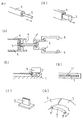
- An example of a simplified diagram for explaining the tire support of the present invention An example of a simplified diagram of a tire support connecting part of claim 1 of the present invention An example of a simplified diagram of a tire support according to claim 1 of the present invention.
- Example of simplified diagram of tire support components usable in the present invention An example of a simplified diagram of a tire support portion usable in the present invention
- An example of a simplified diagram of a tire support portion usable in the present invention An example of a simplified diagram of a tire support portion usable in the present invention
- An example of a simplified diagram of a tire support portion usable in the present invention Simplified illustration of an example of a tire support stopper mechanism usable in the present invention
- An example of a simplified diagram of a tire support usable in the present invention An example of a simplified diagram of a tire support portion usable in the present invention
- Example of simplified diagram of tire support of claim 5 of the present invention Example of simplified diagram of tire support of claim 7 of the present invention
- FIG. 1A shows an example of a wheel, (1) is a wheel, (2) is an axle, and a viewpoint (a) is a viewpoint as viewed from a position parallel to the axle, and a viewpoint (b) ) Shows the viewpoint in the figure viewed from a position perpendicular to the axle.
- cross-section in the left-right direction “cross-section from the top of the tire support”, “cross-section cut in parallel to the axle”, and “view from the position perpendicular to the axle” are the same or These four are viewed from the same direction.
- “circumferential cross section”, “cross section viewed from the side of the tire support”, “cross section cut perpendicular to the axle” and “axle” “view from a parallel position” is a view from the direction in which the four are the same or the four are almost the same.
- the arrows at the viewpoints (a) and (b) in FIG. 1 (A) indicate the direction when viewed with the eyes, but they are described as “parallel or substantially parallel to the axle” according to claim 1 or the like.
- Near direction is the direction of the arrow of the viewpoint (a).
- joint means “joint” or “connected object”, and there are “slidable joint” that can rotate with each other and “rigid joint” that does not move (see Kanaiki Industrial Glossary, Japan Machinist Co., Ltd.). ) Is a “slidable joint” in the joint of claim 1 of the present invention.
- the joint of claim 4 can include the joint of “rigid joint” by having claim 1 in the configuration.
- FIG. 1B is a view of FIG. 1A viewed from a direction parallel to the axle, and shows that the wheel (1) has a ring shape.
- the outer circle of) is the edge of the tire outer periphery
- the inner circle of (1) is the inner edge of the tire.
- the directions indicated by the arrows in FIG. 1B are the “front and rear ends with respect to the rotational direction of the wheel” direction, the “tire circumferential direction”, and the “circumferential direction of the wheel”. The same direction.
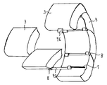
- FIG. 1 shows a simplified diagram partially showing a tire support at the time of dividing a tire puncture described in the claims of the present invention when viewed from the same direction as (B) of FIG. 3)
- (3a) and (3b) are the tire support at the time of the divided tire puncture or the tire support portion at the time of the divided tire puncture, and “both front and rear ends with respect to the rotation direction of the wheel” in (3a) Is the direction of (3) and (3b) on the left and right of (3a), and in (3b) is the direction of (3a) and (3) on the left and right of (3b).
- the adjacent tire support portions described in the range and specification are (3a) and (3b) in this figure, but the shape, structure and material type of the adjacent tire support portions in the claims of the present invention are limited. It is not a thing.
- FIG. 1 shows the tire support at the time of tire puncture that divides in (C) in FIG. 1 from the axle side toward the outer periphery of the tire support, and (3b) described in (C) in FIG.
- a simplified diagram partially showing the outside of the tire is shown, and (3b) in this figure is reciprocated in the direction of the arrow, that is, in the direction parallel to the axle or in the direction substantially parallel to the axle, and is slid.
- (3a) It is moved to the space in the inner edge of the tire (1) in the vicinity, and the "adjacent tire support portions are moved and fixed in a direction parallel to or substantially parallel to the axle". The movement of the tire support portion by the “reciprocating slide guide” is illustrated.
- FIG. 1 is a simplified view of a tire support portion (3b) that rotates (3b) in (D) in FIG. 1 into a space within the inner edge of the tire (1) and rotates around an axis parallel to the axle.
- 3b) rotates in the direction of the arrow
- (3b) enters the space surrounded by the tire and the wheel rim, and the divided tire supports (3a) on both sides of (3b)
- the movement of the tire support portion by the “rotating shaft for connection between tire support portions installed in a direction parallel to the axle or in a direction substantially parallel to the axle” is illustrated.
- FIG. 2 shows a simplified view of an example of a guide for sliding according to claim 1 of the present invention.
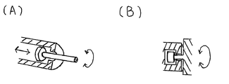
- FIG. 2A shows a cylindrical guide (4) having a cylindrical shaft (5).
- FIG. 2B shows a hole-shaped guide (4) having a prismatic column (5) in the shape of an inner surface of a cylinder having a square shape, in the direction parallel to or substantially parallel to the axle.
- the slide-shaped reciprocating motion is performed by sliding in the direction of the arrows.
- the guide that consists of a hole structure inside the cylinder and a rod that slides through the cylinder structure and the reciprocating guide used in the present invention can perform the same reciprocating movement, its shape, structure, material, and name The type is not limited.
- FIG. 2C is a simplified view of an example of a slide guide for reciprocating motion according to claim 1, and FIG. 2B is included in (4) and slides to reciprocate and encloses the columnar guide of (5).
- a cylindrical columnar guide, (a ′) is a fixing portion of (6) and (4) for maintaining the strength of the shaft by being included and fixed in (a) when the guide is contracted.
- FIG. 2 is examples of a simplified view of a slide guide for reciprocating motion according to claim 1
- (E) in FIG. 2 is a simplified view of (D) in FIG. 2 as viewed from above.
- FIG. 2 shows the lower part of (8) in FIG. 2 (D), and the upper part of the groove in (7) is narrower than the inside.
- a groove-shaped rail guide that can be installed in a direction parallel to or substantially parallel to the axle, and the groove-shaped rail described above. Some shows a simplified diagram similar structure with a shape that fits to the guide links and projection-shaped coupling portion of the slide. "
- FIG. 2 shows a simplified diagram of an example of a connecting arm according to claim 4 of the present invention, and (9) is connected to the tire support portion (3) by a shaft and performs a rotational motion.
- Arms that connect and fix the tire support components at the time of tire puncture can be straight or curved columnar or plate-shaped, latticed with holes, hollowed,
- the type of the shaft is not limited as long as it satisfies the conditions of the present invention, such as one in which the rotating shaft and the sliding guide of claim 1 are connected to a plurality of arms provided at both front and rear ends in the rotational direction of the wheel.
- FIG. 3 shows an example of a simplified diagram of the tire support according to claim 1 of the present invention
- (3) in FIG. 3 (A) is a tire support portion
- the connecting arm (9) is according to claim 1.
- the connecting arms are connected to each other by “an axis installed in a direction parallel to or substantially parallel to the axle” and connected by an axis (10) that rotates in the same direction as the axle, and provided in (3).
- a rotating shaft (10) capable of rotating in the same direction as the axle connected to the connecting portion (8) that slides in the direction of the condition of claim 1 and (11)
- the shape of the support is not limited as long as it satisfies the conditions of the present invention.
- FIG. 3 (B) is a simplified view of FIG. 3 (A) viewed from the axle side, and (9) connected to (8) and (8) is the groove shape according to claim 1 in the direction of the arrow. It has a structure that can be rotated along the inner circumference of the tire so as not to overlap each other by moving along the rail type guide and sliding next (3) It is.
- FIG. 3C is a view obtained by sliding (8) and (9) of FIG. 3B under the conditions of claim 1, and connecting the same shapes in succession.
- the tire support wheel at the time of tire puncture is configured.
- (D) in FIG. 3 is different from the tire support portion in (A) in FIG. 3 in that a guide for moving the slide shaft (8) in the left and right outer directions is installed near the center of (3).
- FIG. 3E is a simplified view of FIG. 3D viewed from the axle side, and (9) and (8) slide outward, but satisfy the conditions of the present invention. As long as there is any type, the shape and structure of the device for sliding are not limited.
- FIG. 3 (F) shows an example of a simplified diagram in which connecting arms in separate tire support portions adjacent to each other are connected, and the plate-shaped connecting arm (9) in FIG. Of the “front and rear ends with respect to the rotational direction of the wheel”, which are respectively connected to the tire support portion by the rotating shaft (10) positioned at one of the front and rear ends with respect to the wheel, and the adjacent tire support portions are between the connecting arms (9). They are respectively connected by a rotating shaft (10 ') located on the other side.
- the types of slide guides for the rotating shaft are the same, and the arm (9), the shaft (10) and the shaft (10) for connecting the tire supporting portions in the first aspect of the present invention. )) (Such as one with two or more arms supporting the tire on one side connected by a shaft), shape, structure, material, etc. Is not limited.
- the joint surface of the tire support portion (3) with the other tire support portion (3) is a curved surface, but the adjacent tire support portion (3) in the tire support portion (3).
- the shape of the joint surface is not limited as long as the shape of the joint surface satisfies the conditions of the present invention.
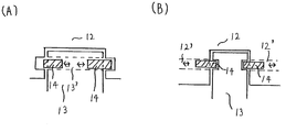
- FIG. 4 shows an example of a simplified diagram of a tire support portion in which a stopper that can be used in the present invention moves parallel or substantially parallel to the axle, and (A) shows a hole (13 ′) provided in the connecting arm (13).
- the connection arm (12) is shown connected by a protrusion (14) that slides and moves, and (B) shows holes (12 ′) provided on both sides of the connection arm (12).
- the stopper for fixation which consists of a plate or a protrusion which is a structure which slides in the direction parallel to the axle
- the type is not limited.
- FIG. 5 is an example of a simplified diagram of a connecting and fixing device that can be used in the present invention.
- FIG. 5A shows a connecting and fixing of a tire support by hooking the connecting and fixing portion (15) and the connecting and fixing portion (15 ′).
- the connecting device (15) for the tire support is pushed by pressing the movable part (15' ') having a spring (16).
- (B) is a view of what is to be attached and detached, and (B) slides (15 ′ ′′) in the direction of the arrow to hold the spring (16) in the configuration, spreads (15 ′′) and opens another fixing portion (15). It is a figure of the coupling device part which also spreads the stopper part to fix in the direction of an arrow.
- FIG. 6 shows a simplified diagram of an example of a tire support during tire puncture that can be used in the present invention.
- FIG. 6A shows a mechanism in which the tire supports can be attached to each other by reciprocating in the direction of the arrows.
- the "protrusions for connecting the tire support parts installed directly on the tire support parts" provided in the support part (3), that is, the detachable protrusions (17) are connected, and are provided in (18) by the force of the spring.
- a protrusion (19) that protrudes or retracts by being pushed and a groove for inserting and fixing (19) is provided in the attaching / detaching protrusion (17) of the tire support.
- FIG. 6B is a cross-sectional view of (3) on the (18) side of FIG. 6A, and an attaching / detaching protrusion (17) having a groove for fixing an adjacent tire support is inserted.
- 6C is a cross-sectional view of (3) on the (17) side of FIG. 6A, and shows a groove having a strength capable of fixing the protrusion of the adjacent tire support (17). It is a tire support (3) which it has in the protrusion for attachment / detachment.
- FIG. 6D is a simplified view of an example of a cross-section of the columnar slide shaft for reciprocating motion according to claim 1, and FIG. 6B is a connecting portion for fixing the guide and the tire support. ) And the cylindrical guide (22) are prevented from coming off by the shape with the barb at the tip.
- a cylindrical rod (20) is provided inside (21), and when the guide is contracted, (20) enters inside (22), and the shaft The structure increases in strength.
- FIG. 6 shows an example of a simplified view of the axle side of the tire support during tire puncture according to the present invention as viewed from the axle side toward the outer circumference of the wheel, and (23) the reciprocating motion according to claim 1 of the present invention.
- a movable and fixed connecting portion of a “connecting and sliding projection connecting portion that is shaped to fit into a groove-shaped rail guide” connected to a “groove-shaped rail guide that can be installed in a substantially parallel direction” ( 8) is connected, and in claim 1, “a column-shaped rail guide that can be installed in a direction parallel to or substantially parallel to the axle and the above-mentioned column-shaped rail guide and a shape for fitting and sliding. Cylindrical shape similar to the mechanism described in ⁇ Hole-shaped connecting part '' The rotating joint movement guide (23) for performing (8) and the tire support portion adjacent the (8 ') in which showed that coupled.
- FIG. 6 (F) shows an example of a simplified view of one tire support of FIG. 6 (E) obliquely viewed from the tire outer periphery, and a ring shape is formed by connecting a plurality of (3). It is.
- FIG. 6 (G) shows a view of the two tire supports aligned in FIG. 6 (E) viewed from the same direction as FIG. 6 (E), and (8) is a guide provided in (3).
- (7 ') is moved in the same direction as the condition of claim 1, and the rod-shaped guides of (23) between (8) and (8') are extended so that (3) arranged side by side do not overlap each other.
- 1 is connected to the tire support portions formed by an axis installed in a direction parallel to or substantially parallel to the axle for maintaining the distance between the adjacent tire support portions and rotating the tire support portions.
- the rotary shaft which can be rotated in a direction parallel to the axle described as “rotary shaft for use” is illustrated.
- FIG. 6 (H) is a simplified view of an example of a cross section of a guide that can be used in the present invention, and (8) due to the return structure between the groove type rail type guides of claim 1 on both sides (7).
- the connecting portion is present so that it can be fixed, and (8) shows the one provided with a guide (23 ′) that performs the same function as (23).
- FIG. 6 shows a simplified view of an example of sliding between tire support parts for fixing a tire support during tire puncture, and is provided in (3) when (3) slides toward each other.
- 3 is a simplified diagram of a stopper mechanism having a protrusion which is pushed down by the side surface of 3) and is pushed out again when it comes close to (25).
- FIG. 7 shows a simplified view of an example of a tire support during tire puncture that can be used in the present invention.
- FIG. 7A shows the deformation of the tire support inside the tire support portion (3) during tire puncture.
- An example of a plate to be restrained is shown in FIG. 1 in which a pillar-shaped slide rail guide (27) according to claim 1 and a groove-shaped rail according to claim 1 are used.
- the structure has a guide (7 ').
- FIG. 7 (B) is a simplified view of FIG. 7 (A) viewed from the side, and (26) has a curved shape in accordance with the shape of the tire support portion (3).
- (C) in FIG. 7 has a guide (7 ') for (8) in the vicinity of the center of (26), and has a shape that can be used in (D) of FIG.
- FIG. 7 shows an example of (8) that can be used in (C) of FIG. 7, and is connected to the left guide and connected to (26) (8L) and the right side.
- the connecting portion (8R) with the guide is shown having a hole (28) for fixing with a bolt penetrating each other.
- FIG. 7 (E) is a view of FIG. 7 (D) from the bottom. (8L) and (8R) allow the bolt (29) to pass through each other, and from the retaining nut (30) and the main nut (31). The one fixed with a check nut is illustrated.
- FIG. 7 (F) is a simplified view of an example of a tire support during tire puncture that can be used in the present invention
- the plate (26) is a guide (7) for moving in the direction from the axle side to the outer periphery of the tire.
- a plate fixing bolt (32) penetrating from the tire outer peripheral direction to the axle side.
- FIG. 7 shows a simplified diagram of an example of a plate for fitting into (F) of FIG. 7, and (35) provided on plate (33) is fitted into (7 ′) of (F) of FIG.
- FIG. 8 shows the moving connecting portion, which is fixed by a nut passing through (32) of FIG. 7 (F) by a hole vertically penetrating the plate (34).
- FIG. 7 is a view of (G) in FIG. 7 as viewed from above, and shows a hole (34) in which the guides (36) and (32) for (8) can be moved. .
- FIG. 7 shows a simplified view of an example of the tire support portion at the time of tire puncture according to the present invention as viewed from the axle side, and a portion (3h) raised on the axle side on the axle side surface of the tire support portion;
- FIG. 2 shows a projection having a raised protrusion (37) and a bolt (38) for fixing the plate, and a groove-type rail guide (7 ′) according to claim 1;
- FIG. 7 shows an example of a simplified view of (37) and (38) of (I) of FIG. 7 as viewed from the side, with washers and nuts attached thereto, and a check nut (30) is attached to the bolt (38). ), (31) and washer (39).
- FIG. 7 shows an example of a simplified diagram of the plate to be attached to (I) in FIG. 7 by (8).
- the plate which comprised the rotating shaft (10) to the arm side and the tire support body side is shown, and if the conditions of this invention are satisfy
- the joint that connects the divided tire support portions may be a composite of “slide”, “rigid joint”, etc., as long as the condition of “slide” of claim 1 is satisfied. Those types are not limited.
- FIG. 8 is an example of a simplified view of a fixing portion of a connecting device for a tire support that can be used in the present invention
- (A) is a top view of the fixing portion
- (41 ′) is a slide of an operating handle (40).
- (40 ') is a hole provided in (40) for allowing the bolt to pass therethrough
- (B) is a cross-sectional view in the vicinity of the fixed portion of (A) ( After the slide of 40), the bolt (42) for fixing (41) and (40) is inserted through the threaded holes (41 ") and (40 ') provided in (41) and fixed. It is the figure which showed the structure.
- FIG. 8C is a simplified diagram showing an example of a method for fixing the tire support portion and the connecting portion that can be used in the present invention
- FIG. 8B is a stopper that can slide and move inside the tire support portion 43.
- (45) is a stopper for fixing (46) through a hole provided in the connecting arm (46), and a block (44) for preventing and fixing the slide (45) is a bolt ( 42), the tire supporting portion and the connecting portion are attached and detached.
- the fixing mechanism used in the present invention may be configured as a connecting arm as shown in FIG. 4 or may be configured as a tire support portion as shown in FIG. 8C, and satisfies the conditions of the present invention. If so, the type is not limited.
- FIG. 9 shows a simplified diagram of an example of a stopper mechanism for a tire support that can be used in the present invention.
- FIG. 9A is a connection stopper (3) provided on one side of the tire support portion (3) in the tire support portion (3). 47) and a shaft (48) having a hole (48) provided in a tire support portion (3) for inserting and fixing (47) on the other, and a rotating shaft (48) for rotating and sliding movements according to claim 1 Rotating movement of the connecting stopper (47) formed in one tire support portion (3) into the fixing hole (48) formed in the other tire supporting portion (3).
- FIG. 9 of the present specification may be configured by combining the stopper mechanism of FIGS. 4, 5 and 8 of this specification and the stopper mechanism of other shapes as long as the conditions of the claims of the present invention are satisfied. If it is, those types are not limited.
- FIG. 9B shows a simplified view of an example of a stopper mechanism that can be used in the present invention, and the protrusion (47) for the stopper provided on the tire support (3) is the rotation according to claim 1 of the present invention. It has a connecting arm (50) having rotating shafts at both ends for moving and sliding.
- FIG. 9C shows a simplified view of (50) of FIG. 9B viewed from the axle side toward the tire outer periphery, and the connecting arm (50) inserts and fixes the hole (47) ( 50 ′).
- FIG. 9D shows a simplified diagram of an example of a stopper mechanism for a tire support that can be used in the present invention.
- a protrusion (47) for stopper provided on one tire support is provided on the other tire support.
- the stopper mechanism inserted and fixed in the hole (50 ') provided in the connected connection arm (50) is shown.
- FIG. 9 (E) shows an example of a simplified view of FIG. 9 (D) viewed from the outer periphery side of the tire toward the axle side.
- the protrusion (47) formed on one tire support (3) has a groove (48 ') for allowing the protrusion (47) formed on the other tire support (3) to pass therethrough. It passes from the tire outer peripheral direction to the tire axle direction and is connected to a fixing hole (50 ′) formed in the connecting arm (50).
- FIG. 9 (F) and 9 (G) are simplified views of an example in which the tip of the connecting arm (47) in FIG. 9 (D) has a bolt shape, and the screw provided at the tip of (47).
- a check nut composed of a set nut (30) and a main nut (31) is fixed to a bolt-shaped part (29 ') cut off.
- FIG. 9H shows an example of a simplified diagram of a tire support connecting portion usable in the present invention, and connecting arms (50) on both sides are connected by a plurality of connecting plate portions (51) and (52).
- the tire supports are connected to each other by a shaft (53) that is connected to pass through (51) and (52) and is capable of rotational movement.
- the type is not limited.
- the attachment and detachment and fixing mechanism described in FIG. 5 and the like is not limited in its type as long as the tire supports can be attached and detached, such as being configured on a surface where the divided tire supports are opposed to each other.
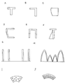
- FIG. 10 shows an example of a simplified diagram of a tire support portion according to the present invention.
- FIGS. 10A to 10F show one side portion of the tire support viewed in a direction perpendicular to the axle and parallel to the axle.
- (G) and (H) are cross sections of the tire support viewed from a direction perpendicular to the axle
- (I) and (J) are views of the tire support portion viewed from a direction parallel to the axle.
- the upper side of the drawings (A) to (J) is the contact portion with the tire inner surface
- the lower portion is the axle side and the portion that contacts the wheel rim.
- (A) shows the part below the ground contact part with the tire
- (B) shows the part supporting the ground contact part with the tire in (A) moved to one side
- (C) shows the tire.
- the inner side wall is curved so that it can be supported along the tire.
- (D) is a hollow shape of (C).
- (E) is the ground contact part from both sides.
- (F) is supported by (A), and this support can be provided on both sides or provided by shifting alternately, or the shape or range of support can be changed.
- the shape of the contact portion with the tire and the portion that supports the contact portion is various, and the type is not limited as long as it satisfies the conditions of the present invention.
- (G) and (H) in FIG. 10 are examples in which the contact surface with the tire is less than two-thirds and the tire support portion is hollow, and the shape and components of the tire support are shown.
- the type of the shape such as the contact interval and the number and the shape of the tire support having a corrugated shape are not limited as long as the conditions of the present invention are satisfied.
- FIG. 10H shows an example in which the same tire run flat tires as those supporting the puncture wheel are arranged side by side.
- (I) and (J) in FIG. 10 are examples in which a hole is formed in the tire support portion.
- the type of the hole is not limited as long as it satisfies the conditions of the present invention, such as the shape and number of holes and the strength of the tire support. Is not limited.
- (I) and (J) of FIG. 10 are tire supports of the type that can be used in the present invention and divide the circumference, and a tire support having a bridge shape by having a cavity for reducing the weight of the tire support. It is a component component.
- the tire support of the present invention is made by forming a ground contact portion with a tire using a polymer compound such as rubber, silicon or foamed material, and the support portion of the ground contact portion is hollow and recyclable hollow metal or carbon material, etc.
- the structure type is not limited as long as it satisfies the conditions of the present invention.
- the tire supports can be fixed to each other by fixing a joint portion between one tire support and the other tire support with a bolt, or by a detachable mechanism having the mechanism shown in FIG.
- a detachable mechanism having the mechanism shown in FIG.
- fixing the tire supports by fitting them with each other by a rotational movement of the shaft, and forming a ring shape of the tire supports.
- Claims of the present invention include tire pressure sensors and passage structures such as gas passage grooves and holes for moving air from the wheel side surface of the tire support to the tire side surface. It is possible to combine without limitation, and the type is not limited.
- FIG. 11 shows an example of a simplified diagram of a tire support structure that can be used in the present invention.
- FIG. 11 (A) shows a connecting arm according to claim 2 having a connecting shaft capable of rotating. is there.
- 11B is a connecting arm according to claim 2 having a hole for connecting to FIG. 11A.
- the shafts of the connecting arms for connecting the adjacent joints of the present invention and the shape of the holes or grooves into which the shafts are inserted are cylindrical in FIGS. 11A and 11B. Even if the part has a shape such as a polygonal column, hole, or groove that does not rotate, if the connecting arm and the tire supporting part to which the connecting arm belongs rotate, the tire support
- the parts themselves can be rotated and their types are not limited as long as they satisfy the conditions of the claims of the present invention.
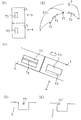
- (C) in FIG. 11 is an example of a simplified diagram in which the joint surfaces of the tire supports are linear, but the facing surfaces and joint surfaces of the tire supports are curved, even if they are face-to-face.
- their types and structures are not limited as long as they satisfy the conditions of the claims of the present invention.
- FIG. 11 shows an example of a simplified diagram of a concave structure that can be used as a stopper portion of a tire support, and the tire support can be fixed by hooking a tire support having a convex structure opposite to the concave structure.
- FIG. 11E is an example of a simplified diagram in which a small recess is provided in FIG. 11D, and the tire support can be fixed by hooking a switch-type stopper as shown in FIG. 5 in the small recess. It is a thing.
- FIG. 11 (F) is an example of a simplified diagram of FIG. 11 (E) in which the indentation is a small protrusion, and the tire support can be fixed by hooking the switch-type stopper of FIG. 5 onto the protrusion. It is a thing.
- FIG. 11 (D), (E), and (F) of FIG. 11 may be used as long as the tire support is fixed arbitrarily, and the shape, structure, The type of material is not limited.
- FIG. 11 are examples of a simplified diagram of the movable part of the fixing switch that can be used in the present invention, and (G) is a slide of the switch in the direction of the arrow.
- the type that operates the fixing mechanism (H) is the type that operates the fixing mechanism by rotating the switch, and (I) is the type that operates the fixing mechanism by pulling the handle. It is a switch part that can be taken down by a shaft provided near the base of the handle and can be brought down, and (G), (H) and (I) in FIG.
- the shape, structure, and type of material are not limited as long as they can fulfill the function to be performed.
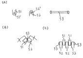
- FIG. 12 shows an example of a simplified diagram of a tire support structure usable in the present invention.
- (A) (51) and (52) are holes (51 ′) and (52 ′) formed in the tire support.
- (53) in (A) is an open connecting hook that connects through the (51) and (52) and is connected to the tire support by a shaft that allows rotational movement, thereby supporting the tire.
- (B) is a mechanism in which a tire support is cut in a direction perpendicular to the axle, and (51) and (52) provided on each tire support (3) are (53).
- (C) is a view of the vicinity of (51) and (52) of FIG. 12 (B) as viewed from the axle side at a position perpendicular to the axle. The shaft of (53) which penetrated through and (52) and was fixed is shown.
- FIG. 13 shows an example of a simplified cross-sectional view of a tire support that can be used in the present invention
- (A) is a cross-sectional view cut in parallel with the axle
- (B) is a line of a divided portion of the tire support of the present invention.
- (C) is a cross-sectional view of a divided tire support component cut perpendicular to the axle
- (D) is a cross-sectional view cut the tire support parallel to the axle
- (54) is a structure for attachment to the vicinity of the wheel rim
- (55) is a wire in one tire support block
- (56) is inside the circumference of the tire support.
- a carcass wheel, (56 ') is a carcass wheel formed on an outer peripheral circular portion in a block of one tire support (3')
- a dotted line (Xa) is a cross section of FIG. Is the part that exists.
- FIG. 13C is a simplified view of a divided tire support as viewed from a position parallel to the axle, and acts like a carcass etc. (56 ′′) but is perpendicular to the axle of the tire support part alone.
- (D) is a simplified view of a divided tire support viewed from a position perpendicular to the axle, and functions similarly to carcass (56 ′′).
- the tire support parts exist in a ring shape in a direction parallel to the axle of the single tire support part, and (56 ′′) is (C) and (D) even if (C) and (D) exist alone. Even if D) is combined, (56 ′′) exists in an oblique direction with respect to (C) or (D), (D) in an oblique direction exists in a single direction, 56 ′′) is not used, and the type is not limited.
- FIG. 14 (A) shows an example of a simplified diagram of a wheel according to claim 7 of the present invention.
- (57) is a tire support portion of a wheel rim having a tire support portion (58).
- (58) Is a wheel rim portion to be connected to (57), and (57 ') and (57) are connected to form the uneven step of (59), and the tire of the present invention near (59) of the wheel rim.
- the shape of (59) in FIG. 14 is a circular shape in which the joint portion between the wheel rim and the tire support is perpendicular to the axle and is flat with respect to the axle so that the wheel rim and the tire support engage with each other.
- the shape of (59) such as a wedge-shaped inclined slope, a circumferential surface formed with straight or curved irregularities, and a tire support supporting part of the wheel arranged inside or outside the joint between the wheels,
- the type of the constituent part is not limited as long as it is of the present invention.
- FIG. 14B shows a wheel (57, 57) having a hole structure penetrating from the axle-side surface near the wheel rim to the tire-side surface in which a tire air leakage prevention packing can be sandwiched.
- 14) is a simplified view in which a packing (60) having the structure of claim 7 in FIG. 14A (a structure in which the diameter of the portion in contact with the tire support is larger than the diameter of the packing portion) is mounted.
- the tire support of the present invention or the wheel of the present invention uses a packing, a seal, a sheet, a film, a ring, or the like that does not depend on the name, and the wheel of the present invention uses Japanese Patent Application No. 2009-241915.
- the type is not limited, for example, the structure or structure is configured.
- FIG. 15A shows a simplified diagram of an example of the stopper mechanism according to claim 4 of the present invention, wherein the arrow 1 is the tire circumferential direction, and consists of a plate that rotates from the axle in the direction of arrow 3 to the wheel outer circumferential direction.
- the fixing arm (61) is an arm insertion space provided in the tire support portion (3Y) ("the fixing hole or groove for connecting or connecting with the joint of the arm or the protrusion in claim 4").
- the arm (61) is fixed by an opening / closing lid that is inserted into (66) and the arm fixing stopper (62) rotates in the direction of arrow 4, and the protrusion provided on the fixing stopper (62) is fixed. It shows the action of a stopper that moves in the direction of arrow 2 by fixing (62) inside the fixing guide (63) by being inserted into (3Y).
- the arm (61) in FIG. 15 (A) is a rotating shaft that performs rotational movement around the tire support (3X) and the axis set in the direction parallel to or substantially parallel to the axle.
- the arm may be expressed as a protrusion, and the shape, structure, material, and the like are not limited as long as the same effect is achieved.
- FIG. 15B shows a simplified diagram of an example of a stopper mechanism that can be used in the present invention, where the arrow 1 is the tire circumferential direction, and is connected to the tire support portion (3X) by a rotating shaft in the direction of the arrow 2.
- a fixing arm (61) made of a plate that rotates from the axle toward the outer circumference of the wheel is inserted into a space for insertion of the arm (61) provided in the tire support portion (3Y).
- Inserting or connecting fixing hole or groove for connection ") (66) and the arm fixing stopper (62 ') is opened and closed by sliding in the circumferential direction of the wheel indicated by the arrow 3 ( 61) is fixed, and a fixing stopper (62 ') is connected to and slides on a slide guide (63') provided on the tire support portion (3) to fix the connecting arm component (61) of the present invention.
- the It is intended to serve as a wrapper.
- FIG. 15 shows that the tire supports have the rotation axis of claim 1 so that the tire support part (X) or the tire support part (Y) rotates in the direction of the arrow so that they can be attached to and detached from each other.
- 65) and the detachable space (66) formed by the hole or groove of (65) provided in the adjacent tire support portion (3Y) are connected to each other, and are protruded or pushed by the force of the spring provided in (65).
- the tire support part (3X) is provided by installing the protrusion (65 ') to be retracted by the groove and the groove (66') provided in (66) for inserting and fixing (65 ') in the tire support part (3).
- tire support part (3Y) And a projection (65) for connecting the tire support portion (X) and the tire support portion (Y) to each other by rotating around an axis installed in a direction parallel to or substantially parallel to the axle.
- 65) satisfies the condition of claim 4 by a space (66) comprising a fixing hole or groove for inserting or connecting.
- 15D is a cross-sectional view of (3) on the (66) side of FIG. 15C, and (3) has a hollow space of (3 ′′) and supports the adjacent tire.
- This is a structure (67) having a groove (66 ′) having a strength capable of fixing the protrusion of the object.
- FIG. 15 shows a sectional view of (3) on the (65) side of (C) of FIG. 15, (3) has a hollow space of (3 ′′), and supports the adjacent tire.
- a protrusion-shaped attaching / detaching device (65) having a protrusion (65 ') that reciprocates by the force of a spring having a strength capable of being inserted and fixed in a space having a groove for fixing an object is joined.
- the structure (67) is illustrated.
- FIG. 16A shows an example of a simplified diagram of the mechanism for attaching and detaching the divided tire support portions according to claim 2
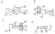
- FIG. 16 68 shows a taper shape for the rotation shaft of FIG.
- (69) in FIG. 16 has a tapered hole in FIG. 11 (B).
- connection stopper (70) that rotates in the direction from the axle side to the wheel outer peripheral side in (68) of (A) in FIG. 16, and (70) is a fixing hole. It is a connecting part for fixation which has (70 ') and is connected and rotated by a rotating shaft (71).
- (72) in FIG. 16 (B) is a nut portion for fixing after being connected to (69), but there are various shapes, structures, and types of materials, and the conditions of the present invention are satisfied. The kind is not limited as long as it satisfies.
- FIG. 16 (C) shows an example of a simplified diagram of a connecting stopper at the distal end of the connecting shaft of claim 2, and the tip provided on the connecting arm (68) has a cylindrical shape.
- a tire support portion installed next to the connecting shaft (68 ′) with a hole for attaching to and detaching from the connecting shaft (68 ′) by a fixing stopper (70) that rotates about the shaft (71).
- This is a connecting arm of the type in which the arm connected to is fixed from both sides indicated by (68) and (70).
- FIG. 16D is a view of the connecting arm 70 shown in FIG. 16C as viewed from the side for fixing, and the arm 70 is rotated in the direction of the arrow by the rotating shaft 71.
- the arm (70) penetrating in the vertical direction in the figure has a fixing hole and a fitting passage hole (70 ") included in the present invention.
- the method of fixing the rotating shaft used in the present invention may be a method in which a fixed object is attached to and detached from the tip of the shaft, or a fixing structure provided on a connecting arm or a tire support, and the kind thereof is limited. do not do.
- the rotating shaft of the present invention indicates the center of motion (see Kojien), that is, the structure that becomes the center that can be rotated, and the rotating shaft is provided on the tire support part, the connecting arm, etc. It can be provided and the type is not limited.
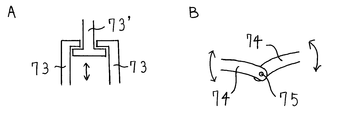
- FIG. 17A shows an example of a simplified diagram of a structure for connecting tire support parts that can be used in the tire support of the present invention
- FIGS. (73) is a cylindrical arm having a stopper protrusion so that the arm of (73 ′) is slid inside and (73) does not pop out.
- There is an arm-like connecting device that can prevent the circumference of the tire support portion from becoming larger than a certain distance without separating the distance between the tire support portions more than a certain distance, and can bring the blocks of the tire support portions closer to each other by a rotational motion.
- FIG. 17B shows an example of a simplified diagram of a tire support that can be used in the tire support of the present invention, and (74) and (74) are connected to both ends of the tire support portion to be separate blocks. (74) and (74) are connected by the rotating shaft (75), and the connecting shape of the arms is changed without changing the distance between the tire supporting portions at the time of attachment / detachment. It shows a connecting arm portion that can be recessed in the circumferential direction.
- the connecting arm connected to the separate tire support portions in FIG. 17 by a rotating shaft may be a wire, a sheet or a chain as long as the conditions of the present invention are satisfied. Those types are not limited as long as the conditions of the term are satisfied.
- FIG. 18A shows an example of a simplified view of a tire support portion that can be used in the present invention as seen from a direction perpendicular to the axle, and the tire support portion (3) and the tire support portion (3 ) Is an example of a portion that overlaps in the direction of the arrow and overlaps, and may satisfy the conditions of the present invention, such as a device for attaching and detaching the tire support portion, or connecting the tire support portion with a complicated surface.
- the type is not limited.
- FIG. 18B shows an example of a simplified cross-sectional view of a tire support portion viewed from a direction perpendicular to the axle that can be used in the present invention, and is provided in the vicinity of the outer periphery of the tire provided in the tire support portion (3) during tire puncture.
- FIG. 19 shows a simplified view of an example of a structural part that can be used in the present invention.
- FIG. 19A is a fastener usable in FIG. 7F
- FIG. 19B is FIG. (77) is a projecting portion that serves as a bolt for the same plate as (26), and (32) is a bolt.
- the hexagonal bolt is fixed by a hexagonal groove inside a projection formed on the plate, so that the bolt is difficult to rotate.
- the types of bolts and plates are not limited, such as those that are bonded or welded or other bolts or structures that suppress the rotation of bolts.
- FIG. 19C is a fastener that can be used in FIG. 7I, etc.
- FIG. 19D is a top view of FIG. 19C
- FIG. 8) is a slide connection portion that performs the same function as the slide connection portion, and (78 ′) is linked to the movable stopper of (79) provided in (78) and slides in the direction of the arrow.
- This is a switch for a stopper that rotates in a direction
- (80) is a guide for sliding the slide connecting portion in the same manner as (7 ') in the vicinity of (3) in (I) of FIG.
- FIG. 19 shows a simplified diagram of an example of a movable part that is connected to the slide connecting part of (78) and the like and connected to a guide having a shape such as (A), (B), or (C) of FIG. (81 ′) is a connecting portion connected to (A), (B), or (C) of FIG. 2, (82) is a connecting portion connected to a slide connecting portion such as (78), (81 ) Shows the movable part of the slide connecting part which is configured integrally with (81 ′) and is movable in the direction of the arrow by being sandwiched between the hemispherical grooves of (82) on the left and right, and is similar to the ball joint.
- a guide having a slightly changed direction can be used.
- the movable part of the guide connecting part is not limited in its kind, for example, by adding other functions as long as it can always move and fix the tire support part of the directional component under the conditions described in the claims of the present invention.
- FIG. 20 is a simplified view of an example of a guide used in the present invention.
- FIG. 20A is a partial view of a slide groove-shaped rail guide that can be configured on the tire support of claim 1 or claim 2.
- (83) is a guide that works in the same manner as (7).
- FIG. 20 (B) shows a protrusion-shaped connecting portion that fits into the rail of claim 1 or claim 2 of the present invention, and (84) is a connecting portion that slides using (83) as a guide.
- FIG. 20 shows an example of a simplified diagram of a plurality of parts obtained by dividing (G) in FIG. 2, (85) is a connecting arm, and (86), (86 ′), ( 86 "), and any or all of (86), (86 ') and (86") are described in FIG. 2 or similar to FIG.
- the attachment / detachment mechanism according to claim 2 may be provided at any location in FIG. 20C, and if the condition of claim 2 is satisfied, the types thereof are as follows: Not limited.
- attachment / detachment mechanism of claim 2 may be the same as that used in other claims such as FIG. 4, FIG. 5, FIG. 8, and FIG.
- FIG. 20D is a simplified view of an example of the rail-shaped sliding rail guide portion according to claim 1 or claim 2 of the present invention, which can be installed in a direction parallel to or substantially parallel to the axle.
- the rail guide (83 ′) is provided directly on the tire support portion (3), and if the guide end is turned back so that the movable portion that slides and moves (83 ′) does not come off, it will be charged. If it becomes a guide of claim
- FIG. 20E shows a simplified view of an example of a columnar slide rail guide according to claim 1 of the present invention, and a columnar rail guide that can be installed in a direction parallel or substantially parallel to the axle ( 83 ′) is provided on the tire support portion (3) via a fixing arm (83 ′′), and has a hole shape for connecting and sliding that fits into the columnar rail guide according to claim 1.
- the connecting portion (84 ′) passes through (83 ′) and slides and moves in the direction of the arrow using (83 ′) as a guide.
- FIG. 21 is an example of a simplified diagram including a tire support component that can be used in the present invention.
- FIG. 21A shows tire support portions on both sides via connecting arms 87 and 87 ′.
- (87) in FIG. 21 (A) is connected to the tire support portion (3) by the rotation shaft (88) of claim 1, and two (87 ') are the three rotation shafts (1) of claim 1. 88 ').
- FIG. 21 (B) is different from FIG. 21 (A) in that the tire support portions (3) are all mounted directly by the rotating shaft (89) and the connecting and fixing pin (90) of claim 1.
- FIG. The shape of the curved portion of the joint surface between the tire support portions may be a straight surface or an uneven surface such as (C) in FIG. 12 or (A) in FIG.
- the shape, structure, material, and the like thereof are not limited as long as they satisfy the conditions of the claims and can be connected to an arbitrary shape.
- tire support portions are connected to form a wheel-shaped tire support.
- the number of tire support portions to be divided is four or five, or seven or more.
- the type is not limited, as is the case with the tire support portions of the other figures described in this specification.
- FIG. 21C shows a simplified diagram in which the inner edge of FIG. 21B is substantially the same as the dotted line (91) indicating the inner edge of the tire or the outer peripheral edge side of the tire from the inner peripheral edge of the tire.
- FIG. 21D has a fixing pin (90) for fixing the tire support portion at the end when the tire support at the time of tire puncture is inserted into the space for entering the tire air.
- FIG. 21E is a simplified view showing the vicinity of adjacent tire supports (3), and FIG. 21E is an adjacent tire support portion (3) having a rotating shaft (89) according to claim 1 that slides in the direction of the arrow.
- FIG. 22 is a simplified diagram showing the vicinity of each other, and the tire support has the structure shown in FIGS. 21D and 21E or the structure shown in FIG. The part of the tire is partially moved to the axle side from the inner edge of the tire. It is possible to small deformation.
- FIGS. 21D and 21E show the tire support portions of the present invention arranged in a zigzag, but the tire support portions are packed so as not to open the gap between the tire support portions (3).
- the zigzag can be reduced by increasing the area of the installation part of the tire support part (3) with the inner surface of the tire when puncturing as shown in FIG. It is possible to adjust the difference in the ground contact portion that comes from the shape.
- FIG. 22 shows an example of a simplified view of the handle portion of claim 3 of the present invention
- (A) is a view of the tire support as viewed from the tire axle side toward the tire outer side
- (92) is for the handle. It is a depression, and it can be moved in the direction of the arrow by holding (92) by hand and can be slid under the conditions of the present invention.
- FIG. 22 (B) is a simplified cross-sectional view of FIG. 22 (A) viewed from the axle side, and the tire support portion (3) is capable of rotating according to claim 1 by the shaft (93). It is.
- FIG. 22 (C) shows an example of a simplified view of the tire support portion of claim 3 as viewed from the axle side, with respect to the recess (92) for the handle formed in the tire support portion (3).
- a handle for the handle installed near the upper part of the hollow (92), that is, near the axle side, and (92 ') is a return type that is installed like a lid that covers a part of the upper part of the hollow (92), that is, near the axle side.
- the handle structure for installing the tire support by gripping (94) with one hand and pulling the other hand to (92 ') and pulling out (3) in the direction of the arrow It is a thing.
- 22 (D) and 22 (E) show an example of a simplified cross-sectional view of FIG. 22 (C) cut in a direction parallel to the axle, and hold the handle (94) or (92 ′).
- FIG. 23 shows an example of a simplified diagram of a tire support according to the present invention, in which a connecting portion (8) for moving a slide guide (7) in each divided tire supporting portion (3) has a columnar connection (95 ) To satisfy the conditions of claim 1.
- (96) in FIG. 23 is a protrusion for fixing an adjacent tire support portion that is directly fixed and installed on the tire support portion (3), and the tire support portion (3) facing the mechanism in FIG. The tire support is finally fixed by the constitution.
- FIG. 24 shows a simplified view of an example of a mechanism for fixing a tire support portion according to claim 6 of the present invention
- (A) is a view of the tire support portion as viewed from the direction of extension of the axle
- (B) is a view of (A).
- (97) A view of the vicinity from the axle side direction to the outer circumferential direction of the tire
- (C) is a view of (B) seen from a direction perpendicular to the axle
- (D) is a vicinity of (98) of (A).
- a stopper (97) having a fixing projection incorporated in the stopper storage space (99) provided in the tire support portion (3Y) is shown in (97).
- the connecting arm of the present invention is connected to the arm (98) and the tire supports (3X) and (3Y). To assist the arm (87) is obtained by allowing more firmly connecting the tire supporting portion (3) with each other.
- the “slide guide (99 ′) in a direction parallel to the tire circumferential direction or substantially parallel to the tire circumferential direction” according to claim 6 is provided inside (3X).
- the guides for sliding the movable connecting arm (98) may be of a type including most of the connecting arms (98).
- a part of the connecting arm may be connected and slid, and the type thereof is not limited.
- FIG. 25 is a simplified view of an example of a mechanism for fixing a tire support portion according to claim 5 of the present invention.
- FIG. 25A is a simplified view of the tire support portion as viewed from the side of FIG. (B) is a simplified view of a tire support portion when claim 5 is viewed from the axle side.
- FIG. 25 is a diagram showing a rotation shaft that performs rotational movement about an axis that is installed in a direction perpendicular to or substantially perpendicular to the axle, provided in the cavity (103) inside the tire support portion (3X).
- the “arm (102) for connecting the tire support portions made up of columns or plates” connected to (101) ” rotates in the direction of the arrow, thereby being provided on the tire support portion (3Y). It shows what connects tire support parts by the space (104) which consists of the hole or groove
- FIG. 26 shows an example of a simplified diagram of the tire support of claim 7 of the present invention
- FIG. 26A is a simplified view of a wheel rim supporting a tire similar to FIG. 14B viewed from the side.
- FIG. 26B is a simplified view of the wheel rim that is sandwiched and fixed between the wheel rims that support the tires on both sides similar to FIG. 14B
- FIG. 26 is a simplified view of the packing sandwiched between (A) and (B) of FIG. 26 to prevent the air of the tire from escaping
- FIG. 26 (D) is the wheel rim and packing of claim 7.
- FIG. 3 shows a partial view of the positional relationship of.
- (105) is a protruding portion provided in (57) and can be fixed by penetrating the bolt (106), and (105 ′) is a groove provided by inserting (105) in (57 ′) and fixing (106 ′). ) Is a threaded hole for inserting and fixing the screw (106).
- (107) is a hole for penetrating (105) provided in the packing of (60), and is in close contact by being crushed by (57) and (57 ').
- FIG. 27 shows an example of a simplified diagram of the tire support of claim 6 of the present invention
- FIG. 27A is a view of claim 6 from the side
- FIG. 27B is the tire of claim 6.
- FIG. 27C is a view of the stopper 98 for (98) viewed from the direction perpendicular to the axle.
- FIG. 27 shows a modification of the fixing method of the slide arm shown in FIG. 24.
- the fixing tool (109) is inserted into the hole (108) provided in (98) inside one tire support (3X). This is an example in which a bolt is passed through and fixed to a bolt penetration hole (110) provided in (109) on the other tire support (3Y) side.
- claim 5 and claim 6 satisfy the respective conditions, their types are not limited.
- FIG. 28 shows an example of a simplified diagram of a tire support portion constituting portion that can be used in the present invention.
- FIG. 28A shows a cross-sectional view in which FIG. Is capable of sliding and rotating.
- (B) in FIG. 28 shows a structure in which (A) in FIG. 28 does not slide but only rotates, and has the same mechanism as (10).
- the fixing device for the connecting arm according to the claims of the present invention is not limited as long as the arm is securely fixed.
- the type of the tire support portion is not limited as long as the tire support portion is provided with an attaching / detaching device or the tire support portion is connected by a complicated surface, so long as the conditions of the present invention are satisfied.
- fittings When used in the present invention, various types of fittings can be used, and the type is not limited.
- the air injection valve that can be used in the wheel rim of the present invention can be the same as that used in a normal wheel rim, and the material, structure, and material of the valve are not limited.
- the type of the mechanism for facilitating the inflow of air from the wheel rim to the inside of the tire in the tire support of the present invention is not limited, for example, the one similar to Japanese Patent Application No. 2010-131095 is used.
- the tire support at the time of tire puncture of the present invention is constituted by the structure of claim 1 in the tire support of the present invention, it is optional to combine other structures, structures, devices and mechanisms, The type is not limited.
- Embodiments of the present invention are as follows. 1. There are various types such as the shape, structure, and material of the parts constituting the wheel. 2.
- a ring-shaped structure capable of maintaining the circumferential length inside the structure of the tire support used in the present invention and deformable is a wire, carcass, chain, plate, roller, ring, net, chain, net, The type of cloth, bead, belt, string, breaker, spring, crawler, caterpillar, block, etc. is not limited as long as it has a shape of a ring that can maintain the length of the circumference and can be deformed. 3.
- channel and hole provided in a wheel will not be limited if the conditions of this invention are satisfy
Landscapes
- Engineering & Computer Science (AREA)
- Mechanical Engineering (AREA)
- Tires In General (AREA)
Priority Applications (3)
| Application Number | Priority Date | Filing Date | Title |
|---|---|---|---|
| US14/346,188 US20150158342A1 (en) | 2011-09-01 | 2012-08-31 | Wheel for coping with tire puncture |
| CN201280045982.5A CN103826877B (zh) | 2012-03-28 | 2012-08-31 | 爆胎应对用车轮 |
| EP12873269.0A EP2832560B1 (fr) | 2012-03-28 | 2012-08-31 | Roue anti-crevaison |
Applications Claiming Priority (2)
| Application Number | Priority Date | Filing Date | Title |
|---|---|---|---|
| JP2012-074233 | 2012-03-28 | ||
| JP2012074233A JP5093865B1 (ja) | 2011-09-01 | 2012-03-28 | パンク対応用車輪 |
Publications (1)
| Publication Number | Publication Date |
|---|---|
| WO2013145366A1 true WO2013145366A1 (fr) | 2013-10-03 |
Family
ID=49261250
Family Applications (1)
| Application Number | Title | Priority Date | Filing Date |
|---|---|---|---|
| PCT/JP2012/072233 Ceased WO2013145366A1 (fr) | 2011-09-01 | 2012-08-31 | Roue anti-crevaison |
Country Status (3)
| Country | Link |
|---|---|
| EP (1) | EP2832560B1 (fr) |
| CN (1) | CN103826877B (fr) |
| WO (1) | WO2013145366A1 (fr) |
Cited By (1)
| Publication number | Priority date | Publication date | Assignee | Title |
|---|---|---|---|---|
| CN109941036A (zh) * | 2019-04-29 | 2019-06-28 | 江苏理工学院 | 一种接地面积可变的安全节能车轮 |
Families Citing this family (1)
| Publication number | Priority date | Publication date | Assignee | Title |
|---|---|---|---|---|
| FR3047693B1 (fr) | 2016-02-16 | 2018-03-02 | Bagolf Limited | Roue pliable |
Citations (13)
| Publication number | Priority date | Publication date | Assignee | Title |
|---|---|---|---|---|
| JPS567885B2 (fr) | 1976-07-17 | 1981-02-20 | ||
| JPS589003B2 (ja) | 1977-07-07 | 1983-02-18 | オ−ツタイヤ株式会社 | 車輪 |
| JP2002200906A (ja) | 2000-12-28 | 2002-07-16 | Bridgestone Corp | 安全空気入りタイヤ |
| JP2003341311A (ja) | 2002-05-28 | 2003-12-03 | Topy Ind Ltd | ランフラットホイールの中子構造 |
| JP2005170379A (ja) | 2003-12-08 | 2005-06-30 | Hutchinson Sa | 自動車用のランフラット装置、およびそれを組み込んだ取り付け組立体 |
| JP2005313690A (ja) | 2004-04-27 | 2005-11-10 | Toyo Tire & Rubber Co Ltd | ランフラットタイヤ支持体及びその製造方法並びにランフラットタイヤ |
| JP2005313791A (ja) | 2004-04-30 | 2005-11-10 | Toyo Tire & Rubber Co Ltd | ランフラットタイヤ用支持体及びランフラットタイヤ |
| JP2007055399A (ja) | 2005-08-24 | 2007-03-08 | Yokohama Rubber Co Ltd:The | タイヤ用ホイール及びホイール/タイヤ組立体 |
| JP2008068857A (ja) | 2006-09-12 | 2008-03-27 | Hutchinson Sa | 自動車のランフラット装置およびこれを備える車輪 |
| JP4102981B2 (ja) | 2002-08-04 | 2008-06-18 | 広慶 藤本 | パンク対応用車輪 |
| JP2009241915A (ja) | 2008-03-11 | 2009-10-22 | Hiroyoshi Fujimoto | パンク対応車輪用パッキン |
| JP2010131095A (ja) | 2008-12-03 | 2010-06-17 | Sankyo Co Ltd | 遊技機 |
| WO2011010536A1 (fr) * | 2009-07-21 | 2011-01-27 | Fujimoto Hiromichi | Roue permettant de gérer un pneu à plat |
Family Cites Families (10)
| Publication number | Priority date | Publication date | Assignee | Title |
|---|---|---|---|---|
| JPS55160610A (en) * | 1979-06-02 | 1980-12-13 | Toyobo Co Ltd | Safety tire for motorcar |
| CN1058232A (zh) * | 1990-07-19 | 1992-01-29 | 中南工业大学 | 从钕铁硼废料中提取钕的方法 |
| CN1058232C (zh) * | 1997-06-16 | 2000-11-08 | 张东顺 | 轮胎安全胎中胎续跑装置 |
| US5988244A (en) * | 1997-06-30 | 1999-11-23 | Chang; Tung-Shun | Safety liner for protecting tubeless tires |
| CN100475569C (zh) * | 2002-05-28 | 2009-04-08 | 都美工业株式会社 | 缺气行驶芯体 |
| ATE392319T1 (de) * | 2002-06-17 | 2008-05-15 | Runflat Internat Ltd | Run-flat-vorrichtung |
| JP2004256062A (ja) * | 2003-02-27 | 2004-09-16 | Yokohama Rubber Co Ltd:The | 自動車用安全車輪及びそのタイヤ支持用中子 |
| JP4091485B2 (ja) * | 2003-07-07 | 2008-05-28 | 東洋ゴム工業株式会社 | ランフラットタイヤ用中子及びその組み付け方法 |
| GB0702156D0 (en) * | 2007-02-05 | 2007-03-14 | Lust Richard | Method and system for fitting a runflat assembly |
| US8800623B2 (en) * | 2010-06-23 | 2014-08-12 | William W. Gardetto | Multi-piece run-flat insert |
-
2012
- 2012-08-31 WO PCT/JP2012/072233 patent/WO2013145366A1/fr not_active Ceased
- 2012-08-31 CN CN201280045982.5A patent/CN103826877B/zh not_active Expired - Fee Related
- 2012-08-31 EP EP12873269.0A patent/EP2832560B1/fr active Active
Patent Citations (13)
| Publication number | Priority date | Publication date | Assignee | Title |
|---|---|---|---|---|
| JPS567885B2 (fr) | 1976-07-17 | 1981-02-20 | ||
| JPS589003B2 (ja) | 1977-07-07 | 1983-02-18 | オ−ツタイヤ株式会社 | 車輪 |
| JP2002200906A (ja) | 2000-12-28 | 2002-07-16 | Bridgestone Corp | 安全空気入りタイヤ |
| JP2003341311A (ja) | 2002-05-28 | 2003-12-03 | Topy Ind Ltd | ランフラットホイールの中子構造 |
| JP4102981B2 (ja) | 2002-08-04 | 2008-06-18 | 広慶 藤本 | パンク対応用車輪 |
| JP2005170379A (ja) | 2003-12-08 | 2005-06-30 | Hutchinson Sa | 自動車用のランフラット装置、およびそれを組み込んだ取り付け組立体 |
| JP2005313690A (ja) | 2004-04-27 | 2005-11-10 | Toyo Tire & Rubber Co Ltd | ランフラットタイヤ支持体及びその製造方法並びにランフラットタイヤ |
| JP2005313791A (ja) | 2004-04-30 | 2005-11-10 | Toyo Tire & Rubber Co Ltd | ランフラットタイヤ用支持体及びランフラットタイヤ |
| JP2007055399A (ja) | 2005-08-24 | 2007-03-08 | Yokohama Rubber Co Ltd:The | タイヤ用ホイール及びホイール/タイヤ組立体 |
| JP2008068857A (ja) | 2006-09-12 | 2008-03-27 | Hutchinson Sa | 自動車のランフラット装置およびこれを備える車輪 |
| JP2009241915A (ja) | 2008-03-11 | 2009-10-22 | Hiroyoshi Fujimoto | パンク対応車輪用パッキン |
| JP2010131095A (ja) | 2008-12-03 | 2010-06-17 | Sankyo Co Ltd | 遊技機 |
| WO2011010536A1 (fr) * | 2009-07-21 | 2011-01-27 | Fujimoto Hiromichi | Roue permettant de gérer un pneu à plat |
Cited By (2)
| Publication number | Priority date | Publication date | Assignee | Title |
|---|---|---|---|---|
| CN109941036A (zh) * | 2019-04-29 | 2019-06-28 | 江苏理工学院 | 一种接地面积可变的安全节能车轮 |
| CN109941036B (zh) * | 2019-04-29 | 2023-09-22 | 江苏理工学院 | 一种接地面积可变的安全节能车轮 |
Also Published As
| Publication number | Publication date |
|---|---|
| CN103826877A (zh) | 2014-05-28 |
| CN103826877B (zh) | 2017-07-04 |
| EP2832560B1 (fr) | 2020-06-24 |
| EP2832560A4 (fr) | 2016-04-06 |
| EP2832560A1 (fr) | 2015-02-04 |
Similar Documents
| Publication | Publication Date | Title |
|---|---|---|
| JP6303235B2 (ja) | 非空気入りタイヤ | |
| US20190001745A1 (en) | Non-pneumatic wheel and method of construction | |
| US20190001744A1 (en) | Non-pneumatic wheel | |
| JP6240815B1 (ja) | フランジ付きタイヤ及びホイール組立体 | |
| US20120060991A1 (en) | Airless tire | |
| CN106414104A (zh) | 热塑性轮毂和非充气轮胎 | |
| US20190001598A1 (en) | Non-pneumatic wheel and method of construction | |
| US20120285595A1 (en) | Foam wheel assembling and positioning structure | |
| RU2012136381A (ru) | Деформируемое сборное колесо | |
| JP2013518755A5 (fr) | ||
| JP5093865B1 (ja) | パンク対応用車輪 | |
| EP2949481B1 (fr) | Pneu non pneumatique creux doté de nervures de renforcement | |
| JP5401192B2 (ja) | 非空気入りタイヤの製造装置および非空気入りタイヤの製造方法 | |
| WO2011010536A1 (fr) | Roue permettant de gérer un pneu à plat | |
| JP3878155B2 (ja) | スポークによりリムとハブを連結した自転車用車輪 | |
| US20110023278A1 (en) | Lock ring mounting/demounting jig | |
| US8733744B2 (en) | Multipiece cushioning assembly for a telescoping shock absorbing assembly | |
| EP2832560B1 (fr) | Roue anti-crevaison | |
| JP2014521551A5 (fr) | ||
| CN115003519B (zh) | 非充气轮胎以及组装非充气轮胎的方法 | |
| JP2012131350A (ja) | 空気入りタイヤ用の中子、中子入りタイヤ、および車両 | |
| KR20150017146A (ko) | 비공기압 타이어 | |
| US9254710B2 (en) | Supporting device for a bicycle wheel | |
| US20170136815A1 (en) | Driver keys for use with wheel rims | |
| JP2012196990A (ja) | タイヤアセンブリ |
Legal Events
| Date | Code | Title | Description |
|---|---|---|---|
| 121 | Ep: the epo has been informed by wipo that ep was designated in this application |
Ref document number: 12873269 Country of ref document: EP Kind code of ref document: A1 |
|
| WWE | Wipo information: entry into national phase |
Ref document number: 2012873269 Country of ref document: EP |
|
| WWE | Wipo information: entry into national phase |
Ref document number: 14346188 Country of ref document: US |
|
| NENP | Non-entry into the national phase |
Ref country code: DE |