WO2013145383A1 - Dispositif d'affichage de résultats de vérification, procédé d'affichage de résultats de vérification, programme, et support de stockage - Google Patents
Dispositif d'affichage de résultats de vérification, procédé d'affichage de résultats de vérification, programme, et support de stockage Download PDFInfo
- Publication number
- WO2013145383A1 WO2013145383A1 PCT/JP2012/075373 JP2012075373W WO2013145383A1 WO 2013145383 A1 WO2013145383 A1 WO 2013145383A1 JP 2012075373 W JP2012075373 W JP 2012075373W WO 2013145383 A1 WO2013145383 A1 WO 2013145383A1
- Authority
- WO
- WIPO (PCT)
- Prior art keywords
- corresponding symbol
- display
- feature point
- image data
- display position
- Prior art date
- Legal status (The legal status is an assumption and is not a legal conclusion. Google has not performed a legal analysis and makes no representation as to the accuracy of the status listed.)
- Ceased
Links
Images


Classifications
-
- G—PHYSICS
- G06—COMPUTING OR CALCULATING; COUNTING
- G06F—ELECTRIC DIGITAL DATA PROCESSING
- G06F16/00—Information retrieval; Database structures therefor; File system structures therefor
- G06F16/50—Information retrieval; Database structures therefor; File system structures therefor of still image data
- G06F16/58—Retrieval characterised by using metadata, e.g. metadata not derived from the content or metadata generated manually
- G06F16/583—Retrieval characterised by using metadata, e.g. metadata not derived from the content or metadata generated manually using metadata automatically derived from the content
- G06F16/5854—Retrieval characterised by using metadata, e.g. metadata not derived from the content or metadata generated manually using metadata automatically derived from the content using shape and object relationship
-
- G—PHYSICS
- G06—COMPUTING OR CALCULATING; COUNTING
- G06V—IMAGE OR VIDEO RECOGNITION OR UNDERSTANDING
- G06V40/00—Recognition of biometric, human-related or animal-related patterns in image or video data
- G06V40/10—Human or animal bodies, e.g. vehicle occupants or pedestrians; Body parts, e.g. hands
- G06V40/12—Fingerprints or palmprints
- G06V40/1347—Preprocessing; Feature extraction
- G06V40/1353—Extracting features related to minutiae or pores
-
- G—PHYSICS
- G06—COMPUTING OR CALCULATING; COUNTING
- G06F—ELECTRIC DIGITAL DATA PROCESSING
- G06F16/00—Information retrieval; Database structures therefor; File system structures therefor
- G06F16/50—Information retrieval; Database structures therefor; File system structures therefor of still image data
- G06F16/58—Retrieval characterised by using metadata, e.g. metadata not derived from the content or metadata generated manually
- G06F16/583—Retrieval characterised by using metadata, e.g. metadata not derived from the content or metadata generated manually using metadata automatically derived from the content
- G06F16/5838—Retrieval characterised by using metadata, e.g. metadata not derived from the content or metadata generated manually using metadata automatically derived from the content using colour
-
- G—PHYSICS
- G06—COMPUTING OR CALCULATING; COUNTING
- G06F—ELECTRIC DIGITAL DATA PROCESSING
- G06F16/00—Information retrieval; Database structures therefor; File system structures therefor
- G06F16/90—Details of database functions independent of the retrieved data types
- G06F16/903—Querying
- G06F16/90335—Query processing
-
- G—PHYSICS
- G06—COMPUTING OR CALCULATING; COUNTING
- G06F—ELECTRIC DIGITAL DATA PROCESSING
- G06F18/00—Pattern recognition
- G06F18/20—Analysing
- G06F18/22—Matching criteria, e.g. proximity measures
-
- G—PHYSICS
- G06—COMPUTING OR CALCULATING; COUNTING
- G06V—IMAGE OR VIDEO RECOGNITION OR UNDERSTANDING
- G06V10/00—Arrangements for image or video recognition or understanding
- G06V10/98—Detection or correction of errors, e.g. by rescanning the pattern or by human intervention; Evaluation of the quality of the acquired patterns
- G06V10/987—Detection or correction of errors, e.g. by rescanning the pattern or by human intervention; Evaluation of the quality of the acquired patterns with the intervention of an operator
-
- G—PHYSICS
- G06—COMPUTING OR CALCULATING; COUNTING
- G06V—IMAGE OR VIDEO RECOGNITION OR UNDERSTANDING
- G06V40/00—Recognition of biometric, human-related or animal-related patterns in image or video data
- G06V40/10—Human or animal bodies, e.g. vehicle occupants or pedestrians; Body parts, e.g. hands
- G06V40/12—Fingerprints or palmprints
- G06V40/1347—Preprocessing; Feature extraction
-
- G—PHYSICS
- G06—COMPUTING OR CALCULATING; COUNTING
- G06V—IMAGE OR VIDEO RECOGNITION OR UNDERSTANDING
- G06V40/00—Recognition of biometric, human-related or animal-related patterns in image or video data
- G06V40/10—Human or animal bodies, e.g. vehicle occupants or pedestrians; Body parts, e.g. hands
- G06V40/12—Fingerprints or palmprints
- G06V40/1365—Matching; Classification
-
- G—PHYSICS
- G06—COMPUTING OR CALCULATING; COUNTING
- G06V—IMAGE OR VIDEO RECOGNITION OR UNDERSTANDING
- G06V40/00—Recognition of biometric, human-related or animal-related patterns in image or video data
- G06V40/10—Human or animal bodies, e.g. vehicle occupants or pedestrians; Body parts, e.g. hands
- G06V40/12—Fingerprints or palmprints
- G06V40/1365—Matching; Classification
- G06V40/1371—Matching features related to minutiae or pores
Definitions
- the present invention relates to a verification result display device, a verification result display method, a program, and a recording medium.
- Biometric features such as fingerprints and palm prints are used for personal authentication in criminal investigations. After confirming the result of the custody of the custody collected at the crime scene, etc., when the verification result is visually confirmed in a court or the like, a document showing the verification result is submitted as evidence. In this document, it is necessary to compare the remnant palm print with the candidate stamp print and indicate which parts of the feature points match each other (see, for example, Patent Document 1).
- FIG. 6A shows an example of a collation result automatically created. There are many places where lines connecting feature points and numbers assigned to the feature points intersect, making it difficult to distinguish. It is necessary for the operator to manually change the arrangement of the lines to the state shown in FIG. 6B so that it is easy to visually check such a collation result.
- the present invention provides a collation result display device that facilitates visual confirmation of the display result of feature points when displaying the feature points of matching collation results based on the query result information of the collation system.
- An object of the present invention is to provide a collation result display method, a program, and a recording medium.
- the verification result display device of the present invention provides: Feature point acquisition means for acquiring a plurality of common feature points in at least two image data to be collated; When the same corresponding symbol is assigned to the common feature point in the at least two image data, when the feature point and the corresponding symbol are connected by a display line, another feature point and another feature point Display position determining means for determining a display position of the corresponding symbol so as not to overlap a display line connecting the corresponding symbol of The display unit includes display means for assigning the corresponding symbol to the display position and displaying the feature point and the corresponding symbol of the feature point by a display line.
- the verification result display method of the present invention is: A feature point acquisition step of acquiring a plurality of common feature points in at least two image data to be collated; When the same corresponding symbol is assigned to the common feature point in the at least two image data, when the feature point and the corresponding symbol are connected by a display line, another feature point and another feature point A display position determining step for determining a display position of the corresponding symbol so as not to overlap a display line connecting the corresponding symbol of A display step of assigning the corresponding symbol to the display position, and displaying the feature point and the corresponding symbol of the feature point by a display line.
- the program of the present invention is characterized in that the verification result display method of the present invention can be executed by a computer.
- the recording medium of the present invention records the program of the present invention.
- a matching result display device that facilitates visual confirmation of the feature point display results, A verification result display method, a program, and a recording medium can be provided.
- FIG. 1 is a block diagram showing an example of the configuration of the collation result display device of the present invention.
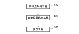
- FIG. 2 is a flowchart showing processing performed by the collation result display device of the present invention.
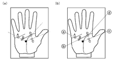
- FIG. 3 is a schematic diagram for explaining an example of the display position determining step in the present invention.
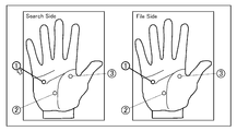
- FIG. 4 is a schematic diagram for explaining an example of the display of the collation result in the present invention.
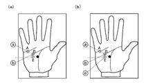
- FIG. 5 is a schematic diagram for explaining another example of the display position determining step in the present invention.
- FIG. 6 is a diagram illustrating an example of a collation result display in the related art.
- the display position determining means obtains a straight line passing through each of the plurality of feature points starting from the center of the image data, and in a region on the image where the corresponding symbol can be displayed. It is preferable that the position on the straight line is a means for determining the arrangement position of the corresponding symbol. Further, in the verification result display method of the present invention, the display position determination step obtains a straight line passing through each of the plurality of feature points from the center of the image data, and an area on the image where the corresponding symbol can be displayed. It is preferable to be a step of determining the position on the straight line as the arrangement position of the corresponding symbol.
- the display position determining means obtains distribution information of each feature point for each of the at least two image data, and each of the image data from the distribution information. Determine the center point of the distribution of feature points, find the straight line passing through each of the plurality of feature points, starting from the center point, and the position on the straight line in the area where the corresponding symbol can be displayed.
- the means for determining the arrangement position of the corresponding symbol is preferable.
- the display position determination step acquires distribution information of each feature point for each of the at least two image data, and for each of the image data from the distribution information A center point of the distribution of each feature point is determined, a straight line passing through each of the plurality of feature points is obtained from the center point, and is on the straight line in an area on the image where the corresponding symbol can be displayed.
- the position is a step of determining the position of the corresponding symbol.
- the display position determining means sequentially determines a display position for the plurality of feature points, and when there is a feature point for which the display position of the corresponding symbol has already been determined, When the display position of the corresponding symbol is determined, the display line connecting the feature point and the corresponding symbol should not intersect or overlap the display line connecting the corresponding symbol and the feature point whose display position has already been determined. It is preferable to adjust the display position of the corresponding symbol given later.
- the display position is sequentially determined for the plurality of feature points, and when there are feature points for which the display positions of the corresponding symbols have already been determined,
- the display line connecting the feature point and the corresponding symbol does not intersect or overlap the display line connecting the corresponding symbol and the feature point whose display position has already been determined.
- the display position determination means further adjusts the display positions of the same corresponding symbols given in the at least two image data so as to coincide with each other.
- the display position determination step further adjusts the display positions of the same corresponding symbols provided in the at least two image data so as to coincide with each other. .
- the image data to be collated is at least one of a fingerprint and a palm print.
- the image data to be verified is at least one of a fingerprint and a palm print.
- collation result display device collation result display method, program, and recording medium of the present invention.
- present invention is not limited to the following embodiment.
- FIG. 1 is a block diagram showing an example of the configuration of the collation result display device of the present invention.
- FIG. 2 is a flowchart of the collation result display method of the present invention.
- the verification result display device 100 includes a feature point acquisition unit 10, a display position determination unit 20, and a display unit 30.
- the present invention is used, for example, in processing when a remnant palmprint collected at a crime scene is requested for collation to a database and a collation result is displayed.
- Feature point acquisition means 10 acquires a plurality of common feature points in at least two image data to be collated (feature point acquisition step: step S10).
- one of the at least two image data is image data of a remnant palm print or a fingerprint that is collation source data, and the other is a candidate print palm print or a candidate imprint fingerprint stored as a database that is a collation target data.
- a plurality of common image data collected from the collation source to be collated, and collation destination image data having feature points similar to the image data of the collation source extracted from the image data stored as a database Are obtained by the feature point obtaining means 10. These image data can be collated by comparing two, or can be collated by combining three or more.
- Step S20 When the same corresponding symbols are assigned to the feature points common to the at least two image data by the display position determining means 20, the feature points and the corresponding symbols are connected by display lines.
- the display positions of the corresponding symbols on the respective images of the at least two image data are determined so as not to overlap the display lines connecting the other feature points and the corresponding symbols of the other feature points (display position determination).
- Step S20 To prevent display lines connecting multiple feature points and their corresponding symbols from overlapping each other, the distribution information for each feature point collation source and collation destination image data can be determined multiple times. Analysis is performed using an algorithm, and the display position on each of the images is determined based on the result.
- the display means 30 assigns the corresponding symbol to the display position on the image determined by the display position determining means 20, and connects the feature points and the corresponding symbols of the feature points with display lines (display).
- Step S30 The corresponding symbol can be such that the feature points considered to be the same in the feature point of the matching source data and the feature point of the matching destination data are the same symbol, for example, a feature with high confidence in matching. Numbers can be added and displayed in ascending order from the point.
- FIG. 3 is a diagram for explaining a display position determination step when this determination algorithm is used. As shown in FIG. 3, for example, when two feature points A and B among feature points A, B, C, and D exist on the same straight line, feature point A that is away from the center.
- a display line connecting the feature point B and the corresponding symbol is determined as the position on the straight line in the corresponding symbol display area. It is also preferable to use an algorithm in which the position of the corresponding symbol is determined by shifting to a position that does not intersect with a straight line passing through other feature points starting from. At this time, it is preferable that the arrangement position of the corresponding symbol of the feature point B is determined to be the closest arrangement position from the arrangement position of the corresponding symbol of the feature point A.
- the display position determining means 20 may further adjust the display positions of the same corresponding symbols given in the at least two image data so as to coincide with each other.
- the same corresponding symbols are arranged at the same position with respect to the images because the discrimination becomes easier.
- a pair combination may be specified by selecting a pair marker.
- the pair marker refers to a set of “circle surrounding feature point”, “corresponding symbol”, and “line connecting each”.
- FIG. 4 shows collation source data
- the right figure shows collation destination data. For example, a collation result as shown is obtained.
- the mouse cursor (arrow in the figure) is moved to the first corresponding symbol in the left figure, the color of the first marker in the left figure is changed and displayed.
- the marker corresponding to the first corresponding symbol in the right figure is also displayed in the same color.
- the combination part of a pair can be displayed in an easy-to-understand manner.
- the present invention is not limited to this and can be similarly applied to a fingerprint. Further, for example, application to biometric authentication information such as veins and irises is also possible.
- the display position determination unit 20 acquires distribution information of each feature point for each of the at least two image data, and from the distribution information, Determine the center point of the distribution. Then, starting from the center point, a straight line passing through each of the plurality of feature points is obtained, and a position on the straight line in an area on the image where the corresponding symbol can be displayed is determined as an arrangement position of the corresponding symbol. Means.
- the center point of the distribution of each feature point determined from the distribution information can be, for example, the position of the center of gravity of each feature point.
- the display position of the corresponding symbol can be determined in the same manner as in the second embodiment, except that the center point of the distribution of the feature points is used, and the matching result can be displayed. .
- the starting point is one place, but the present invention is not limited to this.
- the center point in each region may be set as the starting point.
- a straight line may be obtained starting from the center point at the closest position.
- the display position determining means 20 sequentially determines the display position of the corresponding symbol for a plurality of feature points.
- the corresponding point is determined when determining the display position of the corresponding symbol to be added later.
- the display position of the corresponding symbol given later is adjusted so that the display line connecting the symbol does not intersect or overlap the display line connecting the corresponding symbol whose display position has already been determined and the feature point.
- two feature points A and B exist on a straight line that starts from the center of the image data and passes through the feature points.
- the display line connecting the two Since the display line connecting the two is shifted from the straight line, the original position of the display line for the feature point E for which the display position of the corresponding symbol is to be determined subsequently intersects the display line for the feature point B. (FIG. 5A).
- the display line connecting the feature point E and the corresponding symbol does not cross or overlap the display line connecting the corresponding symbol whose display position has already been determined and the feature point B, as shown in FIG.
- the display position of the corresponding symbol for the feature point E given later may be adjusted.
- the program of this embodiment is a program that can execute the above-described verification result display method on a terminal.
- the program of this embodiment may be recorded on a recording medium, for example.
- the recording medium is not particularly limited, and examples thereof include a random access memory (RAM), a read-only memory (ROM), a hard disk (HD), an optical disk, and a floppy (registered trademark) disk (FD).
- a matching result display device that facilitates visual confirmation of the feature point display results, A verification result display method, a program, and a recording medium can be provided.
- the present invention can be applied not only effectively to the creation of forensic evidence but also in a wide range of applications.
- Matching result display device 10 Feature point acquisition means 20
- Display position determination means 30 Display means A to E Feature points a to e Corresponding symbols respectively corresponding to feature points A to E
Landscapes
- Engineering & Computer Science (AREA)
- Theoretical Computer Science (AREA)
- Physics & Mathematics (AREA)
- General Physics & Mathematics (AREA)
- Multimedia (AREA)
- Data Mining & Analysis (AREA)
- Databases & Information Systems (AREA)
- Human Computer Interaction (AREA)
- General Engineering & Computer Science (AREA)
- Library & Information Science (AREA)
- Computer Vision & Pattern Recognition (AREA)
- Computational Linguistics (AREA)
- Quality & Reliability (AREA)
- Evolutionary Computation (AREA)
- Evolutionary Biology (AREA)
- Bioinformatics & Computational Biology (AREA)
- Bioinformatics & Cheminformatics (AREA)
- Artificial Intelligence (AREA)
- Life Sciences & Earth Sciences (AREA)
- Collating Specific Patterns (AREA)
- Processing Or Creating Images (AREA)
Abstract
Priority Applications (6)
| Application Number | Priority Date | Filing Date | Title |
|---|---|---|---|
| US14/387,898 US11106724B2 (en) | 2012-03-28 | 2012-10-01 | Matching result display device, matching result display method, program, and recording medium |
| JP2014507312A JP5979451B2 (ja) | 2012-03-28 | 2012-10-01 | 照合結果表示装置、照合結果表示方法、プログラムおよび記録媒体 |
| US17/443,029 US12141194B2 (en) | 2012-03-28 | 2021-07-20 | Matching result display device, matching result display method, program, and recording medium |
| US18/384,946 US12118034B2 (en) | 2012-03-28 | 2023-10-30 | Matching result display device, matching result display method, program, and recording medium |
| US18/384,950 US12118035B2 (en) | 2012-03-28 | 2023-10-30 | Matching result display device, matching result display method, program, and recording medium |
| US18/903,204 US12450283B2 (en) | 2012-03-28 | 2024-10-01 | Matching result display device, matching result display method, program, and recording medium |
Applications Claiming Priority (2)
| Application Number | Priority Date | Filing Date | Title |
|---|---|---|---|
| JP2012-074711 | 2012-03-28 | ||
| JP2012074711 | 2012-03-28 |
Related Child Applications (2)
| Application Number | Title | Priority Date | Filing Date |
|---|---|---|---|
| US14/387,898 A-371-Of-International US11106724B2 (en) | 2012-03-28 | 2012-10-01 | Matching result display device, matching result display method, program, and recording medium |
| US17/443,029 Continuation US12141194B2 (en) | 2012-03-28 | 2021-07-20 | Matching result display device, matching result display method, program, and recording medium |
Publications (1)
| Publication Number | Publication Date |
|---|---|
| WO2013145383A1 true WO2013145383A1 (fr) | 2013-10-03 |
Family
ID=49258724
Family Applications (1)
| Application Number | Title | Priority Date | Filing Date |
|---|---|---|---|
| PCT/JP2012/075373 Ceased WO2013145383A1 (fr) | 2012-03-28 | 2012-10-01 | Dispositif d'affichage de résultats de vérification, procédé d'affichage de résultats de vérification, programme, et support de stockage |
Country Status (3)
| Country | Link |
|---|---|
| US (5) | US11106724B2 (fr) |
| JP (1) | JP5979451B2 (fr) |
| WO (1) | WO2013145383A1 (fr) |
Cited By (3)
| Publication number | Priority date | Publication date | Assignee | Title |
|---|---|---|---|---|
| WO2017051861A1 (fr) * | 2015-09-25 | 2017-03-30 | 日本電気株式会社 | Dispositif de comparaison d'empreintes digitales résiduelles et procédé de comparaison d'empreintes digitales résiduelles |
| WO2018079630A1 (fr) * | 2016-10-26 | 2018-05-03 | 日本電気株式会社 | Dispositif de support d'examen d'image à motifs à bandes, procédé de support d'examen d'image à motifs à bandes, et programme |
| WO2025191753A1 (fr) * | 2024-03-13 | 2025-09-18 | 日本電気株式会社 | Dispositif de traitement d'informations, procédé de traitement d'informations et support d'enregistrement |
Families Citing this family (7)
| Publication number | Priority date | Publication date | Assignee | Title |
|---|---|---|---|---|
| US10421012B2 (en) | 2016-03-25 | 2019-09-24 | Zero Latency PTY LTD | System and method for tracking using multiple slave servers and a master server |
| US10486061B2 (en) | 2016-03-25 | 2019-11-26 | Zero Latency Pty Ltd. | Interference damping for continuous game play |
| US10717001B2 (en) | 2016-03-25 | 2020-07-21 | Zero Latency PTY LTD | System and method for saving tracked data in the game server for replay, review and training |
| US9916496B2 (en) * | 2016-03-25 | 2018-03-13 | Zero Latency PTY LTD | Systems and methods for operating a virtual reality environment using colored marker lights attached to game objects |
| US10071306B2 (en) | 2016-03-25 | 2018-09-11 | Zero Latency PTY LTD | System and method for determining orientation using tracking cameras and inertial measurements |
| US10002284B2 (en) * | 2016-08-11 | 2018-06-19 | Ncku Research And Development Foundation | Iterative matching method and system for partial fingerprint verification |
| US10751609B2 (en) | 2016-08-12 | 2020-08-25 | Zero Latency PTY LTD | Mapping arena movements into a 3-D virtual world |
Citations (2)
| Publication number | Priority date | Publication date | Assignee | Title |
|---|---|---|---|---|
| JP2003036443A (ja) * | 2001-07-23 | 2003-02-07 | Nec Software Chubu Ltd | 特徴点表示装置、その方法、及びそのプログラム |
| JP2004078434A (ja) * | 2002-08-13 | 2004-03-11 | Nec Corp | 縞模様画像鑑定装置および縞模様画像鑑定方法 |
Family Cites Families (21)
| Publication number | Priority date | Publication date | Assignee | Title |
|---|---|---|---|---|
| DE3176625D1 (en) * | 1980-10-20 | 1988-02-25 | De La Rue Printrak | Fingerprint minutiae matcher |
| EP0098152B1 (fr) | 1982-06-28 | 1988-12-28 | Nec Corporation | Méthode et dispositif de comparaison d'empreintes digitales normalisées |
| US6356898B2 (en) | 1998-08-31 | 2002-03-12 | International Business Machines Corporation | Method and system for summarizing topics of documents browsed by a user |
| JP3725998B2 (ja) * | 1999-10-14 | 2005-12-14 | 富士通株式会社 | 指紋照合装置及び照合方法 |
| US6690397B1 (en) | 2000-06-05 | 2004-02-10 | Advanced Neuromodulation Systems, Inc. | System for regional data association and presentation and method for the same |
| US20030037034A1 (en) | 2001-08-16 | 2003-02-20 | Tim Daniels | System and method for lubricants supply chain management |
| JP2003271960A (ja) * | 2002-03-12 | 2003-09-26 | Matsushita Electric Ind Co Ltd | 指紋照合装置および指紋照合方法とプログラム |
| US6980211B2 (en) * | 2002-06-04 | 2005-12-27 | Springsoft, Inc. | Automatic schematic diagram generation using topology information |
| EP1671199A2 (fr) | 2003-04-24 | 2006-06-21 | Secureinfo Corporation | Methode, systeme et article de fabrication pour la conservation de donnees et pour distribution logicielle electronique automatique dans un systeme d'entreprise |
| US7450741B2 (en) | 2003-06-23 | 2008-11-11 | Motorola, Inc. | Gray scale matcher |
| US7318199B2 (en) * | 2003-09-11 | 2008-01-08 | Oracle International Corporation | Algorithm for automatic layout of objects in a database |
| JP4174452B2 (ja) | 2004-05-10 | 2008-10-29 | 中部日本電気ソフトウェア株式会社 | 掌紋照合における掌紋表示方法及び掌紋照合装置 |
| JP4756876B2 (ja) | 2004-06-09 | 2011-08-24 | キヤノン株式会社 | 画像表示制御装置、画像表示制御方法、プログラム、及び記憶媒体 |
| US20070136406A1 (en) * | 2005-12-12 | 2007-06-14 | Softky William R | Method and system for numerical computation visualization |
| US8699824B2 (en) | 2006-12-28 | 2014-04-15 | Nokia Corporation | Method, apparatus and computer program product for providing multi-feature based sampling for relevance feedback |
| CN101425065B (zh) * | 2007-10-31 | 2013-01-09 | 日电(中国)有限公司 | 实体关系挖掘设备和方法 |
| US20090237405A1 (en) * | 2008-03-03 | 2009-09-24 | Justsystems Corporation | Data processing apparatus and data processing method |
| JP5563231B2 (ja) | 2009-03-25 | 2014-07-30 | 日本電気株式会社 | 縞模様画像鑑定装置、縞模様画像鑑定方法及びプログラム |
| EP2472469A1 (fr) * | 2009-08-25 | 2012-07-04 | Nec Corporation | Dispositif de support d'examen d'image à motifs à bandes, procédé de support d'examen d'image à motifs à bandes et programme |
| US8498473B2 (en) | 2010-08-24 | 2013-07-30 | Compuware Corporation | System for computationally quantifying similarities between images |
| US8885961B2 (en) | 2010-09-07 | 2014-11-11 | Siemens Aktiengesellschaft | System and method for image denoising optimizing object curvature |
-
2012
- 2012-10-01 WO PCT/JP2012/075373 patent/WO2013145383A1/fr not_active Ceased
- 2012-10-01 US US14/387,898 patent/US11106724B2/en active Active
- 2012-10-01 JP JP2014507312A patent/JP5979451B2/ja active Active
-
2021
- 2021-07-20 US US17/443,029 patent/US12141194B2/en active Active
-
2023
- 2023-10-30 US US18/384,946 patent/US12118034B2/en active Active
- 2023-10-30 US US18/384,950 patent/US12118035B2/en active Active
-
2024
- 2024-10-01 US US18/903,204 patent/US12450283B2/en active Active
Patent Citations (2)
| Publication number | Priority date | Publication date | Assignee | Title |
|---|---|---|---|---|
| JP2003036443A (ja) * | 2001-07-23 | 2003-02-07 | Nec Software Chubu Ltd | 特徴点表示装置、その方法、及びそのプログラム |
| JP2004078434A (ja) * | 2002-08-13 | 2004-03-11 | Nec Corp | 縞模様画像鑑定装置および縞模様画像鑑定方法 |
Cited By (5)
| Publication number | Priority date | Publication date | Assignee | Title |
|---|---|---|---|---|
| WO2017051861A1 (fr) * | 2015-09-25 | 2017-03-30 | 日本電気株式会社 | Dispositif de comparaison d'empreintes digitales résiduelles et procédé de comparaison d'empreintes digitales résiduelles |
| WO2018079630A1 (fr) * | 2016-10-26 | 2018-05-03 | 日本電気株式会社 | Dispositif de support d'examen d'image à motifs à bandes, procédé de support d'examen d'image à motifs à bandes, et programme |
| JPWO2018079630A1 (ja) * | 2016-10-26 | 2019-09-26 | 日本電気株式会社 | 縞模様画像鑑定支援装置、縞模様画像鑑定支援方法及びプログラム |
| US11036961B2 (en) | 2016-10-26 | 2021-06-15 | Nec Corporation | Striped pattern image examination support apparatus, striped pattern image examination support method, and program |
| WO2025191753A1 (fr) * | 2024-03-13 | 2025-09-18 | 日本電気株式会社 | Dispositif de traitement d'informations, procédé de traitement d'informations et support d'enregistrement |
Also Published As
| Publication number | Publication date |
|---|---|
| US12141194B2 (en) | 2024-11-12 |
| US12450283B2 (en) | 2025-10-21 |
| JP5979451B2 (ja) | 2016-08-24 |
| US11106724B2 (en) | 2021-08-31 |
| US20240071129A1 (en) | 2024-02-29 |
| JPWO2013145383A1 (ja) | 2015-12-10 |
| US20250021597A1 (en) | 2025-01-16 |
| US12118035B2 (en) | 2024-10-15 |
| US20240062577A1 (en) | 2024-02-22 |
| US20220156313A1 (en) | 2022-05-19 |
| US20150088863A1 (en) | 2015-03-26 |
| US12118034B2 (en) | 2024-10-15 |
Similar Documents
| Publication | Publication Date | Title |
|---|---|---|
| JP5979451B2 (ja) | 照合結果表示装置、照合結果表示方法、プログラムおよび記録媒体 | |
| JP5277804B2 (ja) | 指紋認証装置、指紋認証プログラムおよび指紋認証方法 | |
| CN106716446B (zh) | 具有模板更新的指纹认证 | |
| JP6491959B2 (ja) | 情報処理装置、情報処理方法及びプログラム | |
| JP6810392B2 (ja) | 個体識別装置 | |
| CN110516458B (zh) | 基于区块链技术的数据处理方法、装置和计算机设备 | |
| US9996733B2 (en) | User authentication via image manipulation | |
| US10764563B2 (en) | 3D enhanced image correction | |
| JP2023174900A5 (fr) | ||
| JP7173197B2 (ja) | 縞模様画像鑑定支援装置、縞模様画像鑑定支援方法及びプログラム | |
| US8260060B2 (en) | Comparison method, comparison system, computer, and program | |
| EP1933270A1 (fr) | Procede et dispositif de recherche d'image | |
| JP2009232002A (ja) | 電子署名システム、署名装置、検証装置、及びプログラム | |
| WO2016184032A1 (fr) | Procédé et appareil de recherche d'images et support de stockage | |
| JP6442873B2 (ja) | 指紋画像処理装置、指紋画像処理方法及びプログラム | |
| Majeed et al. | Fusing different color-space channels in a single-layer image for presentation attack detection | |
| JP5188290B2 (ja) | アノテーション装置、アノテーション方法およびプログラム | |
| JP7414124B2 (ja) | 指紋照合装置、指紋照合方法、及び、プログラム | |
| JP2019070868A5 (fr) | ||
| CN102498500A (zh) | 创建供生物特征验证设备使用的生物特征信息的方法、验证方法及验证设备 | |
| JP2007140703A (ja) | 保険証読取方法、そのシステム及び保険証認識装置 | |
| AU2021103274A4 (en) | Design and Analysis of Image Forgery Detection Techniques for Innovative methodologies. | |
| JP2014021510A (ja) | 画像処理装置および画像処理方法、ならびに、プログラム | |
| JP7014000B2 (ja) | 画像処理プログラム、装置、及び方法 | |
| HK40032311B (en) | Method, apparatus, device and storage medium for eliminating mismatching points of palm prints |
Legal Events
| Date | Code | Title | Description |
|---|---|---|---|
| 121 | Ep: the epo has been informed by wipo that ep was designated in this application |
Ref document number: 12873142 Country of ref document: EP Kind code of ref document: A1 |
|
| ENP | Entry into the national phase |
Ref document number: 2014507312 Country of ref document: JP Kind code of ref document: A |
|
| WWE | Wipo information: entry into national phase |
Ref document number: 14387898 Country of ref document: US |
|
| NENP | Non-entry into the national phase |
Ref country code: DE |
|
| 122 | Ep: pct application non-entry in european phase |
Ref document number: 12873142 Country of ref document: EP Kind code of ref document: A1 |