WO2013145451A1 - Soupape d'injection pour cylindre du type à allumage par étincelle - Google Patents
Soupape d'injection pour cylindre du type à allumage par étincelle Download PDFInfo
- Publication number
- WO2013145451A1 WO2013145451A1 PCT/JP2012/081730 JP2012081730W WO2013145451A1 WO 2013145451 A1 WO2013145451 A1 WO 2013145451A1 JP 2012081730 W JP2012081730 W JP 2012081730W WO 2013145451 A1 WO2013145451 A1 WO 2013145451A1
- Authority
- WO
- WIPO (PCT)
- Prior art keywords
- injection hole
- fuel injection
- fuel
- valve
- injection
- Prior art date
- Legal status (The legal status is an assumption and is not a legal conclusion. Google has not performed a legal analysis and makes no representation as to the accuracy of the status listed.)
- Ceased
Links
Images


Classifications
-
- F—MECHANICAL ENGINEERING; LIGHTING; HEATING; WEAPONS; BLASTING
- F02—COMBUSTION ENGINES; HOT-GAS OR COMBUSTION-PRODUCT ENGINE PLANTS
- F02M—SUPPLYING COMBUSTION ENGINES IN GENERAL WITH COMBUSTIBLE MIXTURES OR CONSTITUENTS THEREOF
- F02M61/00—Fuel-injectors not provided for in groups F02M39/00 - F02M57/00 or F02M67/00
- F02M61/16—Details not provided for in, or of interest apart from, the apparatus of groups F02M61/02 - F02M61/14
- F02M61/18—Injection nozzles, e.g. having valve seats; Details of valve member seated ends, not otherwise provided for
- F02M61/1806—Injection nozzles, e.g. having valve seats; Details of valve member seated ends, not otherwise provided for characterised by the arrangement of discharge orifices, e.g. orientation or size
- F02M61/1813—Discharge orifices having different orientations with respect to valve member direction of movement, e.g. orientations being such that fuel jets emerging from discharge orifices collide with each other
-
- F—MECHANICAL ENGINEERING; LIGHTING; HEATING; WEAPONS; BLASTING
- F02—COMBUSTION ENGINES; HOT-GAS OR COMBUSTION-PRODUCT ENGINE PLANTS
- F02M—SUPPLYING COMBUSTION ENGINES IN GENERAL WITH COMBUSTIBLE MIXTURES OR CONSTITUENTS THEREOF
- F02M51/00—Fuel-injection apparatus characterised by being operated electrically
- F02M51/06—Injectors peculiar thereto with means directly operating the valve needle
- F02M51/061—Injectors peculiar thereto with means directly operating the valve needle using electromagnetic operating means
- F02M51/0625—Injectors peculiar thereto with means directly operating the valve needle using electromagnetic operating means characterised by arrangement of mobile armatures
- F02M51/0664—Injectors peculiar thereto with means directly operating the valve needle using electromagnetic operating means characterised by arrangement of mobile armatures having a cylindrically or partly cylindrically shaped armature, e.g. entering the winding; having a plate-shaped or undulated armature entering the winding
- F02M51/0671—Injectors peculiar thereto with means directly operating the valve needle using electromagnetic operating means characterised by arrangement of mobile armatures having a cylindrically or partly cylindrically shaped armature, e.g. entering the winding; having a plate-shaped or undulated armature entering the winding the armature having an elongated valve body attached thereto
-
- F—MECHANICAL ENGINEERING; LIGHTING; HEATING; WEAPONS; BLASTING
- F02—COMBUSTION ENGINES; HOT-GAS OR COMBUSTION-PRODUCT ENGINE PLANTS
- F02M—SUPPLYING COMBUSTION ENGINES IN GENERAL WITH COMBUSTIBLE MIXTURES OR CONSTITUENTS THEREOF
- F02M51/00—Fuel-injection apparatus characterised by being operated electrically
- F02M51/06—Injectors peculiar thereto with means directly operating the valve needle
- F02M51/061—Injectors peculiar thereto with means directly operating the valve needle using electromagnetic operating means
- F02M51/0625—Injectors peculiar thereto with means directly operating the valve needle using electromagnetic operating means characterised by arrangement of mobile armatures
- F02M51/0664—Injectors peculiar thereto with means directly operating the valve needle using electromagnetic operating means characterised by arrangement of mobile armatures having a cylindrically or partly cylindrically shaped armature, e.g. entering the winding; having a plate-shaped or undulated armature entering the winding
- F02M51/0671—Injectors peculiar thereto with means directly operating the valve needle using electromagnetic operating means characterised by arrangement of mobile armatures having a cylindrically or partly cylindrically shaped armature, e.g. entering the winding; having a plate-shaped or undulated armature entering the winding the armature having an elongated valve body attached thereto
- F02M51/0675—Injectors peculiar thereto with means directly operating the valve needle using electromagnetic operating means characterised by arrangement of mobile armatures having a cylindrically or partly cylindrically shaped armature, e.g. entering the winding; having a plate-shaped or undulated armature entering the winding the armature having an elongated valve body attached thereto the valve body having cylindrical guiding or metering portions, e.g. with fuel passages
-
- F—MECHANICAL ENGINEERING; LIGHTING; HEATING; WEAPONS; BLASTING
- F02—COMBUSTION ENGINES; HOT-GAS OR COMBUSTION-PRODUCT ENGINE PLANTS
- F02M—SUPPLYING COMBUSTION ENGINES IN GENERAL WITH COMBUSTIBLE MIXTURES OR CONSTITUENTS THEREOF
- F02M61/00—Fuel-injectors not provided for in groups F02M39/00 - F02M57/00 or F02M67/00
- F02M61/16—Details not provided for in, or of interest apart from, the apparatus of groups F02M61/02 - F02M61/14
- F02M61/18—Injection nozzles, e.g. having valve seats; Details of valve member seated ends, not otherwise provided for
- F02M61/1806—Injection nozzles, e.g. having valve seats; Details of valve member seated ends, not otherwise provided for characterised by the arrangement of discharge orifices, e.g. orientation or size
- F02M61/1833—Discharge orifices having changing cross sections, e.g. being divergent
-
- F—MECHANICAL ENGINEERING; LIGHTING; HEATING; WEAPONS; BLASTING
- F02—COMBUSTION ENGINES; HOT-GAS OR COMBUSTION-PRODUCT ENGINE PLANTS
- F02M—SUPPLYING COMBUSTION ENGINES IN GENERAL WITH COMBUSTIBLE MIXTURES OR CONSTITUENTS THEREOF
- F02M67/00—Apparatus in which fuel-injection is effected by means of high-pressure gas, the gas carrying the fuel into working cylinders of the engine, e.g. air-injection type
- F02M67/10—Injectors peculiar thereto, e.g. valve less type
- F02M67/12—Injectors peculiar thereto, e.g. valve less type having valves
Definitions
- the present invention is a fuel injection valve used in an internal combustion engine such as a gasoline engine, and the valve body abuts against the valve seat to prevent the fuel from leaking, and the valve body leaves the valve seat so that fuel can be in-cylinder.
- the present invention relates to a spark ignition in-cylinder injection valve that directly injects into the cylinder.
- the fuel injection valve described in the above-mentioned patent documents is a fuel injection valve for a diesel engine. And, in the fuel injection valve described in the above-mentioned patent document, refinement of the fuel is achieved by speeding up the injected fuel. However, in the fuel injection valve described in the above-mentioned patent document, the fuel reach distance (spray length) becomes long, and there is a possibility that the fuel adheres to the intake valve at the time of in-cylinder injection and the in-cylinder wall surface.
- the spark-ignited in-cylinder injection valve according to the invention of claim 1 controls injection of fuel from the injection hole by contacting and separating from the seat member provided with the injection hole and the valve seat of the fuel and the valve seat.
- a spark ignition in-cylinder injection valve comprising at least a valve body, wherein the injection hole comprises an injection hole inlet opening to the inside of the seat member and an injection hole outlet opening to the outside of the seat member, the injection hole In the opening edge of the inlet, a first round chamfer is formed on the upstream side with respect to the flow of fuel toward the injection hole inlet, and the extension length (L) of the injection hole is the diameter of the injection hole diameter (D) It is characterized by being 3 times or less.
- the present invention it is possible to suppress the adhesion of fuel to the intake valve and the inner wall surface of the cylinder when the fuel is injected in the cylinder.
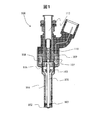
- FIG. 2 is a cross-sectional view of the electromagnetic fuel injection valve of the first embodiment. It is sectional drawing to which the front-end
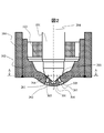
- FIG. 3 is a cross-sectional view of the sheet member shown in FIG. It is a figure explaining the injection hole shape and the flow of fuel.
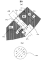
- (A) is a cross-sectional view in which the fuel injection hole is cut parallel to the central axis of the electromagnetic fuel injection valve,
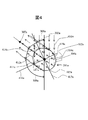
- FIG. It is a figure explaining direction of each injection hole axis. It is a figure explaining the in-plane spreading force of fuel.
- FIG. 1 is a cross-sectional view showing an example of an electromagnetic fuel injection valve as an example of a spark ignition in-cylinder injection valve according to the present embodiment.
- the electromagnetic fuel injection valve 100 is a normally closed electromagnetic drive fuel injection valve used for a direct injection gasoline engine. Therefore, when the coil 108 is deenergized, the valve body 101 is pressed against the seat member 102 by the biasing force of the spring 110, and the fuel is sealed. Such a state is called a valve closing state.
- Fuel is supplied from the fuel supply port 112 to the inside of the electromagnetic fuel injection valve 100.
- the pressure of the supplied fuel is approximately in the range of 1 MPa to 40 MPa.
- FIG. 2 is an enlarged cross-sectional view of the vicinity of a fuel injection hole provided at the tip of the electromagnetic fuel injection valve 100.
- a sheet member 102 is joined to the tip of the nozzle body 104 by welding or the like.
- the inner side of the seat member 102 is a conical surface, and a plurality of fuel injection holes 201 which will be described in detail later are provided.
- the valve body 101 contacts the valve seat surface 203 of the seat member 102 to seal the fuel.
- a contact portion (hereinafter referred to as a spherical portion) 202 with the valve seat surface 203 on the valve body 101 side is formed of a spherical surface. Therefore, the valve seat surface 203 of the conical surface and the spherical portion 202 make a line contact.
- the axial center of the valve body 101 coincides with the central axis 204 of the electromagnetic fuel injection valve 100.
- FIG. 3 is a sectional view of the sheet member 102 shown in FIG.
- description of the valve body 101 is abbreviate
- the case where the number of fuel injection holes 201 provided in the seat member 102 is six will be described as an example.
- the same parts, the same points (positions), etc., of the fuel injection holes 201 are denoted by the same reference numerals, and alphabets a to f corresponding to the fuel injection holes 201 are added to the end of the reference numerals.
- the fuel injection hole 201 has a fuel injection hole inlet 304 and a fuel injection hole outlet 305.
- the opening edge of the fuel injection hole inlet 304 is chamfered in a curved shape.
- the chamfered portion at the fuel injection hole inlet 304 is called a round chamfered portion 1304.
- the fuel injection hole outlet 305 is disposed at a position deeper than the outside of the seat member 102. Therefore, in order to prevent interference with the injected fuel, the sheet member 102 outside the fuel injection hole outlet 305 (below the fuel injection hole outlet 305 in the drawing) is notched.
- the electromagnetic fuel injection valve 100 includes a straight line (hereinafter referred to as an injection hole axis or injection hole axis) 307a connecting the center point 302a of the fuel injection hole inlet 304a and the center point 306a of the fuel injection hole outlet 305a.
- the plane parallel to the central axis 204 of the is called the first plane 11a.
- a fuel injection hole inlet 304a and a fuel injection hole outlet 305a are disposed such that the first plane 11a and the second plane 12a intersect.
- the central axis 204 of the electromagnetic fuel injection valve 100 and the injection hole axis 307a have a positional relationship of twist.
- reference numeral 308 a denotes an angle (nipping angle) formed by the first plane 11 a and the second plane 12 a.
- the positional relationship between the fuel injection hole inlets 304b, 304d, 304e and the fuel injection hole outlets 305b, 305d, 305e in the fuel injection holes 201b, 201d, 201e is the fuel injection hole inlet 304a in the fuel injection hole 201a and the fuel injection hole outlet 305a It is the same as the positional relationship with Therefore, in the fuel injection hole 201b, the first plane 11b and the second plane 12b intersect, and in the fuel injection hole 201d, the first plane 11d and the second plane 12d intersect, and the fuel injection hole 201e Then, the first plane 11 e and the second plane 12 e intersect. That is, the injection hole shafts 307b, 307d, and 307e are in a positional relationship of torsion with the central axis 204 of the electromagnetic fuel injection valve 100, respectively.
- the positional relationship between the fuel injection hole inlets 304c and 304f and the fuel injection hole outlets 305c and 305f in the fuel injection holes 201c and 201f is as follows. That is, in the fuel injection hole 201c, the first plane 11c and the second plane 12c coincide, and in the fuel injection hole 201f, the first plane 11f and the second plane 12f coincide. Therefore, the included angle between the first flat surface 11c and the second flat surface 12c and the included angle between the first flat surface 11f and the second flat surface 12f are 0 degrees.
- the injection hole shafts 307 c and 307 f respectively intersect the central axis 204 of the electromagnetic fuel injection valve 100.
- the fuel injection holes 201a, 201b, 201d, and 201e having a non-zero included angle described above and the fuel injection holes 201c and 201f having a included angle of 0 ° described above have no difference in the effects described later.
- FIG. 4 is a view for explaining the shape of the injection hole and the flow of fuel, taking the fuel injection hole 201a as an example.
- FIG. 5 (a) is a cross-sectional view in which the fuel injection hole 201a is cut in parallel with the central axis 204 of the electromagnetic fuel injection valve 100, taking the fuel injection hole 201a as an example, and in the inside of the fuel injection hole 201a. It is a figure showing the flow of fuel typically.
- FIG. 5B schematically shows a velocity component that spreads in the radial direction of the fuel injection hole 201a among the velocity components of the fuel at the fuel injection hole outlet 305a, taken along the line CC in FIG. 5A.
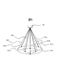
- FIG. 6 is a view for explaining the directions of the injection hole shafts 307a to 307f in the electromagnetic fuel injection valve 100 of the present embodiment.
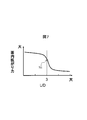
- FIG. 7 is a view for explaining the relationship between the value obtained by dividing the injection hole length by the hole diameter and the in-plane spreading force described later.
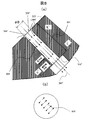
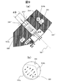
- FIG. 8 and FIG. 9 are diagrams for explaining the prior art, and correspond to FIG. 5 in the present embodiment.
- a plane which bisects the included angle 308a which is an angle formed by the first plane 11a and the second plane 12a is called a virtual plane 413a (see FIG. 4).
- a virtual plane 413a a plane which bisects the included angle 308a which is an angle formed by the first plane 11a and the second plane 12a.
- two portions where the round chamfered portion 1304a at the fuel injection hole inlet 304a and the imaginary plane 413a intersect are shown by points 414a and 415a.
- the radius of curvature of the portion represented by a point 414a upstream with respect to the flow of fuel described later is larger than the radius of curvature of the portion represented by a point 415a downstream with respect to the flow of fuel.
- round chamfers are formed on the entire periphery of the inlet opening edge of the fuel injection hole 201 so that the radius of curvature of the point 414a on the upstream side is larger than the radius of curvature of the point 415a on the downstream side. It is not necessary to form round chamfers all around the inlet opening edge of the fuel injection hole 201, and round chamfers may be appropriately formed only at locations where separation of the fuel flow is unacceptably large. Therefore, the round chamfer may be formed only on the upstream side of the opening edge, and in the present invention, the round chamfer may be formed at least on the upstream side of the injection hole inlet opening edge.
- the fuel flows as described below.
- the fuel supplied from the fuel supply port 112 to the inside of the electromagnetic fuel injection valve 100 is opened, and between the valve seat surface 203 and the spherical portion 202 of the valve body 101. It flows along the valve seat surface 203 toward the fuel injection hole inlet 304 a from the gap generated in the The fuel flow is denoted by reference numeral 410a.
- the fuel flow 410a toward the fuel injection hole inlet 304a is directed in the direction toward the fuel injection hole outlet 305a at the fuel injection hole inlet 304a, that is, the center point 302a of the fuel injection hole inlet 304a and the center point 306a of the fuel injection hole outlet 305a. It is twisted in the direction of the connected injection hole axis 307a.
- the fuel flow is indicated by reference numeral 411a. Thereafter, the fuel flows through the inside of the fuel injection hole 201a toward the fuel injection hole outlet 305a (not shown) in FIG.
- the fuel flow is denoted by reference numeral 412a.
- the fuel bends most rapidly at the point 414a described above, and the inertial force in the direction away from the inner wall surface of the fuel injection hole 201a of the fuel is the largest. Therefore, the fuel is most easily separated from the inner wall surface of the fuel injection hole 201a at the point 414a.
- the fuel bends gently at the above-described point 415a as compared to the point 414a. Therefore, at the point 415a, the fuel is less likely to be separated from the inner wall surface of the fuel injection hole 201a compared to the point 414a.
- the curvature radius of the portion represented by the point 414a upstream with respect to the flow of fuel is the curvature of the portion represented by the point 415a downstream with respect to the flow of fuel Greater than radius. Therefore, separation of fuel from the inner wall surface of the fuel injection hole 201a can be suppressed according to the flow of fuel into the fuel injection hole 201a.
- an included angle 309a also exists at an angle formed by the first plane 11a and the second plane 12a, and the plane that bisects the included angle is
- a virtual plane 416a that bisects the included angle 309a is also conceivable. Then, two portions indicated by the point 417a and the point 418a where the round chamfered portion 1304a and the imaginary plane 416a intersect are also conceivable.
- the included angle 309 a and the virtual plane 416 a are not particularly mentioned.
- the fuel injection hole 201a has an extended length L as the length of the injection hole axis 307a, and the diameter D of the fuel injection hole 201a is parallel to the injection hole axis 307a.
- the diameter of the inner surface 501 a of the hole 201 a is taken as the diameter.
- the fuel flowing along the valve seat surface 203 is prevented from peeling off by the round chamfered portion 1304a of the fuel injection hole inlet 304a, and the fuel flowing into the fuel injection hole 201a is denoted by reference numeral 508a.
- the relationship between the extension length L of the fuel injection hole 201a and the diameter D of the fuel injection hole 201a be L / D ⁇ 3.
- L / D the fuel 508 a flowing into the fuel injection hole 201 a is injected from the fuel injection hole outlet 305 a without being completely rectified inside the fuel injection hole 201 a. Therefore, as shown in FIG. 5B, among the velocity components of the fuel at the fuel injection hole outlet 305a, it is possible to increase the velocity component 509a spreading in the radial direction of the fuel injection hole 201a (in-plane of fuel Spreading power increases).
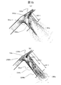
- FIG. 15 shows simulation results by the inventors.
- the fuel flowing into the injection hole inlet 304 from the fuel seal portion at the upper right in each drawing (not shown) flows through the round chamfered portion 1304 a and flows through the fuel injection hole.
- L / D is about 1, it can be seen that the injection is performed without being rectified in the injection hole as shown by 1500a.
- the fuel injection hole 201 ' is formed with respect to the diameter D of the fuel injection hole 201' (the diameter at the inner surface 801 of the fuel injection hole 201 'parallel to the injection hole axis 307').
- the case where the extension length L ′ of L ′ is long, that is, the case where L ′ / D> 3 will be described.
- FIG. 8 (a) corresponds to FIG. 5 (a)
- FIG. 8 (b) corresponds to FIG. 5 (b).
- FIG. 7 shows a curve 701 representing the in-plane spreading force of the fuel, where L / D is on the horizontal axis and the in-plane spreading force of the fuel is on the vertical axis.
- the in-plane spreading force of the fuel depends on the radially spreading velocity component at the injection hole outlet 305.
- the velocity component that spreads in the radial direction at the injection hole outlet 305 is a velocity component that occurs when the fuel flowing into the fuel injection hole 201 is not rectified within the fuel injection hole 201. Therefore, by setting L / D to 3 or less, it is possible to inject fuel from the injection hole outlet 305 without completely rectifying the fuel. This can shorten the spray length.
- FIG. 9A the case where the chamfered portion 1304 in the present embodiment is not provided at the fuel injection hole inlet 304 '' will be described.
- the relationship between the diameter D of the fuel injection hole 201 ′ ′ (the diameter of the inner surface 901 of the fuel injection hole 201 ′ ′) in FIG. 9A and the extension length L of the fuel injection hole 201 ′ ′ is as described above. It is assumed that L / D ⁇ 3 as in the present embodiment.
- FIG. 9 (a) corresponds to FIG. 5 (a)
- FIG. 9 (b) corresponds to FIG. 5 (b).
- the fuel 908 flowing into the fuel injection hole 201 ′ ′ is rectified in the fuel injection hole 201 ′ ′. It is injected from the fuel injection hole outlet 305 '' without any problem.
- the cross-sectional area of the fuel 908 flowing inside the fuel injection hole 201 ′ ′ is smaller than the cross-sectional area of the fuel injection hole 201 ′ ′ by the cross-sectional integration of the separation region generated inside the fuel injection hole 201 ′ ′. Therefore, the area of the fuel injection hole outlet 305 ′ ′ (the cross-sectional area of the fuel injection hole 201 ′ ′) is substantially reduced, so that the injection speed of fuel is increased.
- the spray length becomes long. Therefore, the spray length can not be shortened simply by setting L / D to a small value.
- the arrow representing the velocity component is shown being biased from the center of the cross section of the injection hole. This is due to the difference between the distance between the downstream boundary surface 901a of the fuel flow and the inner surface 901 and the distance between the upstream boundary surface 901b and the inner surface 901 due to the separation in FIG. 9A.
- each of the injection hole axes 307a to 307f is along the generatrix of one of two virtual cones sharing an apex and an axis and having different apex angles.
- the virtual cone having the smaller apex angle is denoted by reference numeral 601
- the other virtual cone is denoted by reference numeral 602.
- the injection hole axes 307a, 307c, and 307e have apexes on the central axis 204 (not shown in FIG. 6) of the electromagnetic fuel injection valve 100 and are along the generatrix of the imaginary cone 601 centered on the central axis 204. .
- the injection hole axes 307 b, 307 d, 307 f share an apex and an axis with the imaginary cone 601, and are along the generatrix of the imaginary cone 602 having an apex angle larger than that of the imaginary cone 601.
- a straight line 307 connecting the center point 302 of the fuel injection hole inlet 304 of the fuel injection hole 201 and the center point 306 of the fuel injection hole outlet 305 is a cone of two virtual cones 601 and 602. It is along the face.
- the electromagnetic fuel injection valve 100 of the present embodiment described above has the following effects.
- (1) The round chamfered portion 1304 is provided at the fuel injection hole inlet 304, and the relationship between the extension length L of the fuel injection hole 201a and the diameter D of the fuel injection hole 201a is L / D ⁇ 3. did.
- separation of fuel that occurs inside the fuel injection holes 201 can be prevented.
- the radius of curvature of the portion represented by the point 414 located upstream with respect to the flow of fuel is greater than the radius of curvature of the portion represented with the point 415 located downstream with respect to the flow of fuel was also configured to be large.
- the fuel injection hole inlet 304 is provided inside the seat member 102 which is a conical surface.
- the flow of fuel toward the fuel injection hole inlet 304 is rectified along the conical surface, so the setting of the curvature radius for each location of the opening edge of the round chamfered portion 1304 becomes easy, and to the fuel injection hole 201 According to the way of fuel flow, separation of fuel from the inner wall surface of the fuel injection hole 201 can be effectively prevented. Therefore, the fuel adhesion to the intake valve and the in-cylinder wall surface at the time of in-cylinder injection can be effectively suppressed.
- the valve seat surface 203 is provided inside the seat member 102 which is a conical surface.
- the flow of fuel toward the fuel injection hole inlet 304 is rectified along the conical surface. Therefore, as described above, separation of fuel from the inner wall surface of the fuel injection hole 201 can be effectively prevented according to the flow of the fuel into the fuel injection hole 201. Therefore, the fuel adhesion to the intake valve and the in-cylinder wall surface at the time of in-cylinder injection can be effectively suppressed.
- Each injection hole axis 307 a-307 f is configured to be along the generatrix of either of two virtual cones 601 and 602 which share apexes and axes and have different apex angles. As a result, various spray shapes can be configured, and the layout of the spray when fuel is injected into the internal combustion engine is excellent.
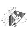
- FIG. 10 is a cross-sectional view showing the configuration of the electromagnetic fuel injection valve 100 according to the second embodiment, which corresponds to FIG. 5 (a).
- the electromagnetic fuel injection valve 100 of the second embodiment is configured such that the cross-sectional area of the fuel injection hole side surface 1001 gradually increases from the fuel injection hole inlet 304 to the fuel injection hole outlet 305.
- the diameter D of the fuel injection hole 201 in the second embodiment is at the boundary between the round chamfered portion 1007 of the fuel injection hole inlet 304 and the fuel injection hole side surface 1001 (the position where the cross-sectional area of the fuel injection hole 201 is minimized).
- the diameter is 1010.
- the fuel 1008 that has flowed in from the valve seat surface 203 without peeling along the rounded chamfer 1007 spreads in the radial direction inside the fuel injection hole 201. After flowing, it is injected from the fuel injection hole outlet 305. Therefore, it is possible to suppress the velocity component in the axial direction of the injection hole by increasing the velocity component of the fuel spreading in the radial direction. Therefore, as compared with the electromagnetic fuel injection valve 100 of the first embodiment, the spray length can be further shortened, so that the fuel adhesion to the intake valve and the in-cylinder wall surface at the time of in-cylinder injection can be effectively suppressed.
- the configuration of the fuel injection valve of the second embodiment is the same as the configuration of the fuel injection valve of the first embodiment, except for the configuration described above. Therefore, for example, the inlet opening edge of the injection hole 201 is chamfered, and the radius of curvature of the point 414a (see FIG. 4) on the upstream side is larger than the radius of curvature of the point 415a (see FIG. 4) on the downstream side. .
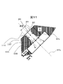
- FIG. 11 is a cross-sectional view showing the configuration of the electromagnetic fuel injection valve 100 of the third embodiment, and is a view corresponding to FIG. 5 (a).
- a round chamfered portion 1107 is provided at the fuel injection hole inlet 304, and a round chamfered portion 1101 is provided at the fuel injection hole outlet 305.
- the downstream end of the round chamfered portion 1107 and the upstream end of the rounded chamfer 1101 coincide with each other.
- the diameter D of the fuel injection hole 201 in the third embodiment is the downstream end of the rounded chamfer 1107 and the upstream end of the rounded chamfer 1101, the rounded chamfer 1107 and the rounded chamfer 1101 (The position where the cross-sectional area of the fuel injection hole 201 is minimized).
- the fuel flows from the valve seat surface 203 along the round chamfered portion 1107 without peeling off.
- the fuel 1108 flows from the fuel injection hole outlet 305 after flowing while spreading in the radial direction at the round chamfered portion 1108. Therefore, it is possible to suppress the velocity component in the axial direction of the injection hole by increasing the velocity component of the fuel spreading in the radial direction. Therefore, as compared with the electromagnetic fuel injection valve 100 of the first embodiment, the spray length can be further shortened, so that the fuel adhesion to the intake valve and the in-cylinder wall surface at the time of in-cylinder injection can be effectively suppressed.
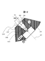
- FIG. 12 is a cross-sectional view showing the configuration of the electromagnetic fuel injection valve 100 of the fourth embodiment, and is a view corresponding to FIG. 5 (a).
- the cross-sectional area of the fuel injection hole side surface 1201 is narrowed from the fuel injection hole inlet 304 to the fuel injection hole outlet 305.
- the diameter D of the fuel injection hole 201 in the fourth embodiment is a diameter 1210 at the boundary between the round chamfered portion 1207 of the fuel injection hole inlet 304 and the fuel injection hole side surface 1201.
- the fuel 1208 that has flowed in from the valve seat surface 203 without peeling along the chamfered portion 1207 is squeezed in the radial direction by the fuel injection hole side surface 1201. After flowing, it is injected from the fuel injection hole outlet 305.
- the velocity component spreading in the radial direction of the fuel injection hole 201 is somewhat suppressed, as compared with the first to third embodiments described above.
- L / D the fuel 1208 flowing into the inside of the fuel injection hole 201 is injected from the fuel injection hole outlet 305 without being completely rectified inside the fuel injection hole 201. Therefore, among the velocity components of the fuel at the fuel injection hole outlet 305, the velocity component spreading in the radial direction of the fuel injection hole 201 becomes large, and the velocity component in the axial direction of the injection hole becomes small. Therefore, since the injection speed of the fuel from the fuel injection hole outlet 305 becomes slow, the spray length of the fuel becomes short, and the adhesion of the fuel to the intake valve and the inner wall surface at the time of in-cylinder injection can be effectively suppressed.
- the flow rate of the entire electromagnetic fuel injection valve 100 can be suppressed. Therefore, the electromagnetic fuel injection valve 100 of the fourth embodiment can be easily used for an internal combustion engine with a small displacement.
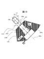
- FIG. 13 is a cross-sectional view showing the configuration of the electromagnetic fuel injection valve 100 according to the fifth embodiment, which corresponds to FIG. 5 (a).
- the cross-sectional shape of the fuel injection hole 201 is an elliptical shape.
- the diameter D of the fuel injection hole 201 in the fifth embodiment is at the boundary between the round chamfered portion 1307 of the fuel injection hole inlet 304 and the fuel injection hole side surface 1301 (position where the cross-sectional area of the fuel injection hole 201 is minimized).
- the ellipse 13 has a major axis labeled 13a and a minor axis labeled 13b.
- fuel injection holes having an elliptical shape so that the major diameter 13a is substantially orthogonal to the flow of fuel flowing from the upstream (upper right in the drawing) of the valve seat 203
- the orientation of the inlet 304 is determined. That is, since the fuel injection hole inlet 304 is largely opened with respect to the flow of the fuel flowing in from the upstream of the valve seat surface 203, compared with the case where the shape of the fuel injection hole inlet 304 is a perfect circle, Peeling of fuel inside the holes 201 can be effectively suppressed.
- the fuel 1308 that has flowed in without peeling off the round chamfered portion 1307 of the fuel injection hole inlet 304 is expanded while being radially spread inside the fuel injection hole 201 and then injected from the fuel injection hole outlet 305. Therefore, it is possible to suppress the velocity component in the axial direction of the injection hole by increasing the velocity component of the fuel spreading in the radial direction. Therefore, compared with the electromagnetic fuel injection valve 100 of the second embodiment in which the cross-sectional area of the fuel injection hole side face is gradually increased from the fuel injection hole inlet to the fuel injection hole outlet, the spray length is Further, it is possible to effectively suppress the adhesion of fuel to the intake valve and the in-cylinder wall surface during in-cylinder injection.
- the same operation and effect as the above-described operation and effect can be obtained.
- the case of the electromagnetic fuel injection valve 100 of the third embodiment the case where the round chamfer is provided at the inlet of the fuel injection hole and the round chamfer is provided at the outlet of the fuel injection hole Even in this case, the same effects as the above-described effects can be obtained.
- the electromagnetic fuel injection valve 100 of the fourth embodiment even when the cross-sectional area of the side surface of the fuel injection hole narrows from the fuel injection hole inlet to the fuel injection hole outlet. The same effects as those described above can be obtained.
- FIG. 14 is a cross-sectional view showing the configuration of the electromagnetic fuel injection valve 100 according to the sixth embodiment, which corresponds to FIG. 5 (a).
- the cross-sectional shape of the fuel injection hole 201 is substantially triangular.
- the diameter D of the fuel injection hole 201 in the sixth embodiment is at the boundary between the round chamfered portion 1407 of the fuel injection hole inlet 304 and the fuel injection hole side surface 1401 (the position where the cross-sectional area of the fuel injection hole 201 is minimized). It is a diameter 1410 of a circle having a cross-sectional area equal to that of the triangle 14.
- the triangle 14 is an equilateral triangle which has the edge which attached
- fuel injection holes having a triangular shape such that the side 14a is substantially orthogonal to the flow of fuel flowing from the upstream (upper right in the drawing) of the valve seat 203 The orientation of the inlet 304 is determined. That is, since the fuel injection hole inlet 304 is largely opened with respect to the flow of the fuel flowing in from the upstream of the valve seat surface 203, compared with the case where the shape of the fuel injection hole inlet 304 is a perfect circle, Peeling of fuel inside the holes 201 can be effectively suppressed.
- the fuel 1408 which has flowed in without peeling off the round chamfered portion 1407 of the fuel injection hole inlet 304 is expanded while flowing radially inside the fuel injection hole 201 and then injected from the fuel injection hole outlet 305. Therefore, it is possible to suppress the velocity component in the axial direction of the injection hole by increasing the velocity component of the fuel spreading in the radial direction. Therefore, compared with the electromagnetic fuel injection valve 100 of the second embodiment in which the cross-sectional area of the fuel injection hole side face is gradually increased from the fuel injection hole inlet to the fuel injection hole outlet, the spray length is Further, it is possible to effectively suppress the adhesion of fuel to the intake valve and the in-cylinder wall surface during in-cylinder injection.
- the same operation and effect as the above-described operation and effect can be obtained.
- the case of the electromagnetic fuel injection valve 100 of the third embodiment the case where the round chamfer is provided at the inlet of the fuel injection hole and the round chamfer is provided at the outlet of the fuel injection hole Even in this case, the same effects as the above-described effects can be obtained.
- the electromagnetic fuel injection valve 100 of the fourth embodiment even when the cross-sectional area of the side surface of the fuel injection hole narrows from the fuel injection hole inlet to the fuel injection hole outlet. The same effects as those described above can be obtained.
- the fuel spray length toward the upper and lower surface and the surface in the inner cylinder of the internal combustion engine becomes appropriate.
- the radius of curvature of the round chamfered portion 1304 may be appropriately set in accordance with the circumferential position of the opening edge of the fuel injection hole inlet 304. By doing this, the mixture of air-fuel mixture in the cylinder becomes good while suppressing the fuel adhesion to the intake valve and the cylinder inner wall surface.
- the radius of curvature of the chamfered portion 1304 it is desirable to set the radius of curvature of the chamfered portion 1304 so as to gradually change along the circumferential direction of the opening edge of the fuel injection hole inlet 304.
- at least the curvature radius of the chamfered portion 1304 needs to have a large or small difference between the upstream side and the downstream side of the fuel flow, and the change of the curvature radius of the chamfered portion 1304 is rapid along the circumferential direction of the opening edge Even if they are discontinuous or not, the effects of the present invention are not impaired.
- at least the opening edge of the fuel injection hole inlet 304 may be chamfered on the upstream side with respect to the flow of fuel, and it is not essential to chamfer on the downstream side.
- the round chamfered portion 1304 can be provided at the opening edge of the fuel injection hole inlet 304 by, for example, circulating a liquid in which an abrasive is dispersed, blasting, or the like.
- a difference in curvature radius from the portion not subjected to heat treatment occurs during chamfering. You may do so.
- the present invention is not limited to the embodiment described above, and can be applied to various spark ignition in-cylinder injection valves.
Landscapes
- Engineering & Computer Science (AREA)
- Chemical & Material Sciences (AREA)
- Combustion & Propulsion (AREA)
- Mechanical Engineering (AREA)
- General Engineering & Computer Science (AREA)
- Physics & Mathematics (AREA)
- Electromagnetism (AREA)
- Fuel-Injection Apparatus (AREA)
Abstract
Priority Applications (4)
| Application Number | Priority Date | Filing Date | Title |
|---|---|---|---|
| DE112012006103.9T DE112012006103T5 (de) | 2012-03-26 | 2012-12-07 | Fremdzündungs-Kraftstoffdirekteinspritzventil |
| US14/379,973 US9677526B2 (en) | 2012-03-26 | 2012-12-07 | Spark-ignition direct fuel injection valve |
| US15/591,218 US10024288B2 (en) | 2012-03-26 | 2017-05-10 | Spark-ignition direct fuel injection valve |
| US16/012,275 US10704518B2 (en) | 2012-03-26 | 2018-06-19 | Spark-ignition direct fuel injection valve |
Applications Claiming Priority (2)
| Application Number | Priority Date | Filing Date | Title |
|---|---|---|---|
| JP2012-068613 | 2012-03-26 | ||
| JP2012068613A JP5959892B2 (ja) | 2012-03-26 | 2012-03-26 | 火花点火式燃料噴射弁 |
Related Child Applications (2)
| Application Number | Title | Priority Date | Filing Date |
|---|---|---|---|
| US14/379,973 A-371-Of-International US9677526B2 (en) | 2012-03-26 | 2012-12-07 | Spark-ignition direct fuel injection valve |
| US15/591,218 Continuation US10024288B2 (en) | 2012-03-26 | 2017-05-10 | Spark-ignition direct fuel injection valve |
Publications (1)
| Publication Number | Publication Date |
|---|---|
| WO2013145451A1 true WO2013145451A1 (fr) | 2013-10-03 |
Family
ID=49258784
Family Applications (1)
| Application Number | Title | Priority Date | Filing Date |
|---|---|---|---|
| PCT/JP2012/081730 Ceased WO2013145451A1 (fr) | 2012-03-26 | 2012-12-07 | Soupape d'injection pour cylindre du type à allumage par étincelle |
Country Status (4)
| Country | Link |
|---|---|
| US (3) | US9677526B2 (fr) |
| JP (1) | JP5959892B2 (fr) |
| DE (1) | DE112012006103T5 (fr) |
| WO (1) | WO2013145451A1 (fr) |
Cited By (4)
| Publication number | Priority date | Publication date | Assignee | Title |
|---|---|---|---|---|
| WO2016152012A1 (fr) * | 2015-03-25 | 2016-09-29 | 株式会社デンソー | Procédé de fabrication d'élément, procédé pour fabriquer des éléments de différents types, dispositif de fabrication d'élément, et système pour fabriquer des éléments de différents types |
| EP3067550A4 (fr) * | 2013-11-07 | 2017-04-19 | Hitachi Automotive Systems, Ltd. | Soupape d'injection de carburant |
| EP3196458A1 (fr) * | 2016-01-22 | 2017-07-26 | Delphi International Operations Luxembourg S.à r.l. | Trou de pulvérisation d'un injecteur de carburant |
| EP3845756A4 (fr) * | 2018-10-26 | 2022-08-10 | Hitachi Astemo, Ltd. | Soupape d'injection de carburant |
Families Citing this family (19)
| Publication number | Priority date | Publication date | Assignee | Title |
|---|---|---|---|---|
| JP5959892B2 (ja) * | 2012-03-26 | 2016-08-02 | 日立オートモティブシステムズ株式会社 | 火花点火式燃料噴射弁 |
| JP6020380B2 (ja) * | 2013-08-02 | 2016-11-02 | 株式会社デンソー | 燃料噴射弁 |
| JP2015212538A (ja) * | 2014-05-07 | 2015-11-26 | 株式会社日本自動車部品総合研究所 | 燃料噴射弁 |
| JP6201908B2 (ja) * | 2014-06-18 | 2017-09-27 | 株式会社デンソー | 燃料噴射弁 |
| JP5969564B2 (ja) | 2014-10-01 | 2016-08-17 | トヨタ自動車株式会社 | 燃料噴射弁 |
| WO2016163086A1 (fr) * | 2015-04-09 | 2016-10-13 | 株式会社デンソー | Dispositif d'injection de carburant |
| JP6292188B2 (ja) * | 2015-04-09 | 2018-03-14 | 株式会社デンソー | 燃料噴射装置 |
| JP2017036678A (ja) * | 2015-08-07 | 2017-02-16 | 日立オートモティブシステムズ株式会社 | 電磁式弁 |
| US20170138251A1 (en) * | 2015-11-12 | 2017-05-18 | Cummins Inc. | Pre-chamber nozzle |
| EP3181855B1 (fr) * | 2015-12-14 | 2018-08-29 | Caterpillar Energy Solutions GmbH | Préchambre de moteur à combustion interne |
| DE102016211688A1 (de) * | 2016-06-29 | 2018-01-04 | Robert Bosch Gmbh | Injektor zum Einspritzen eines Fluids mit sich verjüngendem Einströmbereich einer Durchgangsöffnung |
| WO2018207582A1 (fr) | 2017-05-12 | 2018-11-15 | 日立オートモティブシステムズ株式会社 | Soupape d'injection de carburant |
| US20200025060A1 (en) * | 2018-07-19 | 2020-01-23 | GM Global Technology Operations LLC | Fuel Injector and Nozzle Passages Therefor |
| GB2577251A (en) * | 2018-09-18 | 2020-03-25 | Ford Global Tech Llc | Diesel injectors and method of manufacturing diesel injectors |
| US10808668B2 (en) * | 2018-10-02 | 2020-10-20 | Ford Global Technologies, Llc | Methods and systems for a fuel injector |
| USD934299S1 (en) | 2020-01-29 | 2021-10-26 | Caterpillar Inc. | Injector |
| USD934298S1 (en) | 2020-01-29 | 2021-10-26 | Caterpillar Inc. | Injector |
| JP6868144B1 (ja) * | 2020-05-25 | 2021-05-12 | 株式会社スギノマシン | ノズル |
| US20220170435A1 (en) * | 2020-12-01 | 2022-06-02 | Dynomite Diesel Products | Fuel injector nozzle |
Citations (5)
| Publication number | Priority date | Publication date | Assignee | Title |
|---|---|---|---|---|
| JPH10331747A (ja) * | 1997-06-02 | 1998-12-15 | Denso Corp | 燃料噴射ノズルおよびその製造方法 |
| JP2006510843A (ja) * | 2002-12-20 | 2006-03-30 | ダイムラークライスラー・アクチェンゲゼルシャフト | 直接噴射火花点火内燃機関 |
| JP2006083764A (ja) * | 2004-09-16 | 2006-03-30 | Denso Corp | 燃料噴射ノズル |
| JP2007085333A (ja) * | 2005-08-25 | 2007-04-05 | Denso Corp | 燃料噴射弁 |
| JP2009270448A (ja) * | 2008-05-01 | 2009-11-19 | Mitsubishi Electric Corp | 燃料噴射弁 |
Family Cites Families (32)
| Publication number | Priority date | Publication date | Assignee | Title |
|---|---|---|---|---|
| DE2557772A1 (de) * | 1975-12-20 | 1977-06-23 | Kloeckner Humboldt Deutz Ag | Brennstoffeinspritzventil |
| US5029759A (en) * | 1989-11-17 | 1991-07-09 | Cummins Engine Company, Inc. | Curved hole machining method and fuel injector formed thereby |
| JP3114334B2 (ja) | 1992-02-19 | 2000-12-04 | いすゞ自動車株式会社 | 燃料噴射ノズル及びその製造方法 |
| JPH08232813A (ja) * | 1995-02-27 | 1996-09-10 | Aisan Ind Co Ltd | インジェクタ |
| DE19507171C1 (de) * | 1995-03-02 | 1996-08-14 | Bosch Gmbh Robert | Kraftstoffeinspritzventil für Brennkraftmaschinen |
| EP0809017A1 (fr) * | 1996-05-22 | 1997-11-26 | Steyr-Daimler-Puch Aktiengesellschaft | Injecteur de carburant à deux étages pour moteurs à combustion interne |
| US6644565B2 (en) * | 1998-10-15 | 2003-11-11 | Robert Bosch Gmbh | Fuel injection nozzle for self-igniting internal combustion engines |
| DE19925380A1 (de) * | 1999-06-02 | 2000-12-07 | Volkswagen Ag | Kraftstoffeinspritzventil für Brennkraftmaschinen |
| JP3879909B2 (ja) | 2001-03-29 | 2007-02-14 | 株式会社デンソー | 燃料噴射装置 |
| DE10307931A1 (de) * | 2003-02-25 | 2004-10-28 | Robert Bosch Gmbh | Brennstoffeinspritzventil |
| US6948665B2 (en) | 2003-06-30 | 2005-09-27 | Siemens Vdo Automotive Corporation | Fuel injector including an orifice disc, and a method of forming the orifice disc with an asymmetrical punch |
| US7086615B2 (en) | 2004-05-19 | 2006-08-08 | Siemens Vdo Automotive Corporation | Fuel injector including an orifice disc and a method of forming an oblique spiral fuel flow |
| US20060226264A1 (en) * | 2005-04-08 | 2006-10-12 | Bacho Paul S V Iii | Fuel injector director plate having chamfered passages and method for making such a plate |
| JP2007107459A (ja) | 2005-10-13 | 2007-04-26 | Toyota Motor Corp | 燃料噴射装置 |
| WO2007090019A2 (fr) * | 2006-01-27 | 2007-08-09 | Gm Global Technology Operations, Inc. | Procede et appareil pour un moteur a injection directe a allumage commande |
| EP2041424B1 (fr) * | 2006-07-04 | 2011-09-14 | Renault Trucks | Ensemble de buse, injecteur de carburant et moteur à combustion interne comprenant un tel injecteur |
| EP2047079A1 (fr) * | 2006-08-04 | 2009-04-15 | Toyota Jidosha Kabushiki Kaisha | Moteur à combustion interne à allumage commandé à injection directe et procédé d'injection de carburant pour ledit moteur |
| DE102006041472A1 (de) | 2006-09-05 | 2008-03-06 | Robert Bosch Gmbh | Brennstoffeinspritzventil |
| DE102006041475A1 (de) | 2006-09-05 | 2008-03-06 | Robert Bosch Gmbh | Brennstoffeinspritzventil |
| JP4265645B2 (ja) * | 2006-11-07 | 2009-05-20 | トヨタ自動車株式会社 | 燃料噴射装置 |
| US8011600B2 (en) * | 2006-12-19 | 2011-09-06 | The United States Of America As Represented By The Administrator Of The U.S. Environmental Protection Agency | Fuel injector nozzle |
| GB0712403D0 (en) | 2007-06-26 | 2007-08-01 | Delphi Tech Inc | A Spray Hole Profile |
| JP2009024683A (ja) * | 2007-07-24 | 2009-02-05 | Hitachi Ltd | 複数の噴孔を有するインジェクタ、当該インジェクタを備えた筒内ガソリン噴射型内燃機関とその制御方法 |
| DE102008041676A1 (de) * | 2008-08-29 | 2010-03-04 | Robert Bosch Gmbh | Brennstoffeinspritzventil |
| JP2010053796A (ja) * | 2008-08-29 | 2010-03-11 | Hitachi Ltd | 燃料噴射弁 |
| JP2010112196A (ja) | 2008-11-04 | 2010-05-20 | Keihin Corp | 燃料噴射弁のノズル |
| JP2010222977A (ja) | 2009-03-19 | 2010-10-07 | Toyota Central R&D Labs Inc | 燃料噴射ノズル |
| JP4988791B2 (ja) * | 2009-06-18 | 2012-08-01 | 日立オートモティブシステムズ株式会社 | 燃料噴射弁 |
| US20110030635A1 (en) * | 2009-08-04 | 2011-02-10 | International Engine Intellectual Property Company, Llc | Fuel injector nozzle for reduced coking |
| DE102011077272A1 (de) * | 2011-06-09 | 2012-12-13 | Robert Bosch Gmbh | Einspritzventil für Brennkraftmaschinen |
| DE102011077268A1 (de) * | 2011-06-09 | 2012-12-13 | Robert Bosch Gmbh | Einspritzventil für Brennkraftmaschinen |
| JP5959892B2 (ja) * | 2012-03-26 | 2016-08-02 | 日立オートモティブシステムズ株式会社 | 火花点火式燃料噴射弁 |
-
2012
- 2012-03-26 JP JP2012068613A patent/JP5959892B2/ja active Active
- 2012-12-07 DE DE112012006103.9T patent/DE112012006103T5/de active Pending
- 2012-12-07 WO PCT/JP2012/081730 patent/WO2013145451A1/fr not_active Ceased
- 2012-12-07 US US14/379,973 patent/US9677526B2/en active Active
-
2017
- 2017-05-10 US US15/591,218 patent/US10024288B2/en active Active
-
2018
- 2018-06-19 US US16/012,275 patent/US10704518B2/en active Active
Patent Citations (5)
| Publication number | Priority date | Publication date | Assignee | Title |
|---|---|---|---|---|
| JPH10331747A (ja) * | 1997-06-02 | 1998-12-15 | Denso Corp | 燃料噴射ノズルおよびその製造方法 |
| JP2006510843A (ja) * | 2002-12-20 | 2006-03-30 | ダイムラークライスラー・アクチェンゲゼルシャフト | 直接噴射火花点火内燃機関 |
| JP2006083764A (ja) * | 2004-09-16 | 2006-03-30 | Denso Corp | 燃料噴射ノズル |
| JP2007085333A (ja) * | 2005-08-25 | 2007-04-05 | Denso Corp | 燃料噴射弁 |
| JP2009270448A (ja) * | 2008-05-01 | 2009-11-19 | Mitsubishi Electric Corp | 燃料噴射弁 |
Cited By (5)
| Publication number | Priority date | Publication date | Assignee | Title |
|---|---|---|---|---|
| EP3067550A4 (fr) * | 2013-11-07 | 2017-04-19 | Hitachi Automotive Systems, Ltd. | Soupape d'injection de carburant |
| WO2016152012A1 (fr) * | 2015-03-25 | 2016-09-29 | 株式会社デンソー | Procédé de fabrication d'élément, procédé pour fabriquer des éléments de différents types, dispositif de fabrication d'élément, et système pour fabriquer des éléments de différents types |
| EP3196458A1 (fr) * | 2016-01-22 | 2017-07-26 | Delphi International Operations Luxembourg S.à r.l. | Trou de pulvérisation d'un injecteur de carburant |
| EP3845756A4 (fr) * | 2018-10-26 | 2022-08-10 | Hitachi Astemo, Ltd. | Soupape d'injection de carburant |
| US12135001B2 (en) | 2018-10-26 | 2024-11-05 | Hitachi Astemo, Ltd. | Fuel injection valve |
Also Published As
| Publication number | Publication date |
|---|---|
| US9677526B2 (en) | 2017-06-13 |
| JP5959892B2 (ja) | 2016-08-02 |
| US10024288B2 (en) | 2018-07-17 |
| JP2013199876A (ja) | 2013-10-03 |
| DE112012006103T5 (de) | 2014-12-18 |
| US20170241391A1 (en) | 2017-08-24 |
| US10704518B2 (en) | 2020-07-07 |
| US20150047611A1 (en) | 2015-02-19 |
| US20180363615A1 (en) | 2018-12-20 |
Similar Documents
| Publication | Publication Date | Title |
|---|---|---|
| WO2013145451A1 (fr) | Soupape d'injection pour cylindre du type à allumage par étincelle | |
| CN103703242B (zh) | 燃料喷射阀 | |
| JP6186130B2 (ja) | 燃料噴射弁及び燃料噴射弁の製造方法 | |
| US20170321636A1 (en) | Gas injector including an outwardly opening valve closure element | |
| CN102619658A (zh) | 燃料喷射阀 | |
| US9133803B2 (en) | Fuel injector having a plurality of flow-through regions | |
| JP6339628B2 (ja) | 燃料噴射弁 | |
| JP5976065B2 (ja) | 燃料噴射弁 | |
| JP6619472B2 (ja) | 燃料噴射弁 | |
| CN112368475B (zh) | 燃料喷射阀 | |
| JP6121870B2 (ja) | 燃料噴射装置の微粒化技術 | |
| JP5320116B2 (ja) | 燃料噴射弁 | |
| CN105705770A (zh) | 燃料喷射阀 | |
| JP6591597B2 (ja) | 燃料噴射弁 | |
| JP6318278B2 (ja) | 燃料噴射弁 | |
| CN105952564A (zh) | 燃料喷射阀 | |
| WO2016121482A1 (fr) | Structure d'orifice d'admission pour moteur | |
| CN107532557A (zh) | 燃料喷射装置 | |
| JP2016029284A (ja) | 燃料噴射弁 | |
| JP6899756B2 (ja) | 燃料噴射弁 | |
| JP2017036678A (ja) | 電磁式弁 | |
| JP2019124225A (ja) | 燃料噴射装置 | |
| JP2015101978A (ja) | 燃料噴射弁 |
Legal Events
| Date | Code | Title | Description |
|---|---|---|---|
| 121 | Ep: the epo has been informed by wipo that ep was designated in this application |
Ref document number: 12872726 Country of ref document: EP Kind code of ref document: A1 |
|
| WWE | Wipo information: entry into national phase |
Ref document number: 14379973 Country of ref document: US |
|
| WWE | Wipo information: entry into national phase |
Ref document number: 1120120061039 Country of ref document: DE Ref document number: 112012006103 Country of ref document: DE |
|
| 122 | Ep: pct application non-entry in european phase |
Ref document number: 12872726 Country of ref document: EP Kind code of ref document: A1 |