WO2013145484A1 - 制御回路、および制御回路を備える発電装置 - Google Patents
制御回路、および制御回路を備える発電装置 Download PDFInfo
- Publication number
- WO2013145484A1 WO2013145484A1 PCT/JP2012/083506 JP2012083506W WO2013145484A1 WO 2013145484 A1 WO2013145484 A1 WO 2013145484A1 JP 2012083506 W JP2012083506 W JP 2012083506W WO 2013145484 A1 WO2013145484 A1 WO 2013145484A1
- Authority
- WO
- WIPO (PCT)
- Prior art keywords
- phase
- period
- generator
- control circuit
- output voltage
- Prior art date
- Legal status (The legal status is an assumption and is not a legal conclusion. Google has not performed a legal analysis and makes no representation as to the accuracy of the status listed.)
- Ceased
Links
Images


Classifications
-
- H—ELECTRICITY
- H02—GENERATION; CONVERSION OR DISTRIBUTION OF ELECTRIC POWER
- H02P—CONTROL OR REGULATION OF ELECTRIC MOTORS, ELECTRIC GENERATORS OR DYNAMO-ELECTRIC CONVERTERS; CONTROLLING TRANSFORMERS, REACTORS OR CHOKE COILS
- H02P9/00—Arrangements for controlling electric generators for the purpose of obtaining a desired output
- H02P9/009—Circuit arrangements for detecting rotor position
-
- H—ELECTRICITY
- H02—GENERATION; CONVERSION OR DISTRIBUTION OF ELECTRIC POWER
- H02P—CONTROL OR REGULATION OF ELECTRIC MOTORS, ELECTRIC GENERATORS OR DYNAMO-ELECTRIC CONVERTERS; CONTROLLING TRANSFORMERS, REACTORS OR CHOKE COILS
- H02P9/00—Arrangements for controlling electric generators for the purpose of obtaining a desired output
-
- G—PHYSICS
- G01—MEASURING; TESTING
- G01R—MEASURING ELECTRIC VARIABLES; MEASURING MAGNETIC VARIABLES
- G01R29/00—Arrangements for measuring or indicating electric quantities not covered by groups G01R19/00 - G01R27/00
- G01R29/18—Indicating phase sequence; Indicating synchronism
-
- H—ELECTRICITY
- H02—GENERATION; CONVERSION OR DISTRIBUTION OF ELECTRIC POWER
- H02P—CONTROL OR REGULATION OF ELECTRIC MOTORS, ELECTRIC GENERATORS OR DYNAMO-ELECTRIC CONVERTERS; CONTROLLING TRANSFORMERS, REACTORS OR CHOKE COILS
- H02P23/00—Arrangements or methods for the control of AC motors characterised by a control method other than vector control
- H02P23/14—Estimation or adaptation of motor parameters, e.g. rotor time constant, flux, speed, current or voltage
Definitions
- the present invention relates to a control circuit for determining the phase order of a multiphase AC generator and a power generation apparatus including the control circuit.
- a multi-phase AC generator is sometimes used to generate electric power to be supplied to a load (see, for example, Patent Document 1).
- an object of the present invention is to determine the phase order of a multiphase AC generator.
- the present invention proposes the following items in order to solve the above-described problems.
- the present invention provides a control circuit for determining the phase sequence of an n-phase AC generator (where n is an integer satisfying n ⁇ 2) (for example, equivalent to the generator 5 in FIG. 1) (for example, in FIG. The control circuit 1), and the timing for determining the phase order of the n-phase AC generator by detecting the timing when the output voltage output from each of the n-phases crosses a predetermined threshold value
- a control circuit including a means e.g., corresponding to the determination unit 13 in FIG. 1.
- the determination means is provided in the control circuit for determining the phase sequence of the n-phase AC generator.
- the determination means detects the timing at which the voltage output from each of the n phases crosses a predetermined threshold and determines the phase order of the n-phase AC generator. For this reason, the phase sequence of the n-phase AC generator can be determined.
- the present invention provides period acquisition means (for example, period acquisition unit 12 of FIG. 1) for determining the period of the n-phase AC generator (for example, equivalent to the sensor period T of FIG. 7) for the control circuit of (1). If the time obtained by dividing the period obtained by the period obtaining unit by n is referred to as a specific time (for example, equivalent to 1 / 3T in FIG.
- the determination unit The output voltage during a period from the specified time x times (where x is an integer satisfying 0 ⁇ x ⁇ n ⁇ 1) from the specified reference timing to (x + 1) times before the specified time from the reference timing
- a control circuit characterized in that a phase determination procedure is performed for obtaining one of the n phases for which the phase becomes equal to or higher than a predetermined threshold voltage.
- the period obtaining means for obtaining the period of the n-phase AC generator is provided in the control circuit of (1). Then, if the time obtained by dividing the period obtained by the period obtaining unit by the above-mentioned n is referred to as a specific time, the determination unit performs the phase order determination procedure. In the phase sequence determination procedure, the output voltage becomes equal to or higher than a predetermined threshold voltage during a period from a specific time x times before a predetermined reference timing to (x + 1) specific times before the reference timing. One phase was determined from n phases.
- phase sequence can be determined for various n-phase AC generators, and a highly versatile control circuit can be realized.
- the present invention relates to a period acquisition means (for example, the period acquisition unit 12 of FIG. 1) for obtaining the period of the n-phase AC generator (for example, corresponding to the sensor period T of FIG. 7) for the control circuit of (1). If the time obtained by dividing the period obtained by the period obtaining unit by n is referred to as a specific time (for example, equivalent to 1 / 3T in FIG.
- the determination unit The output voltage during a period from the specified time x times (where x is an integer satisfying 0 ⁇ x ⁇ n ⁇ 1) from the specified reference timing to (x + 1) times before the specified time from the reference timing
- the period obtaining means for obtaining the period of the n-phase AC generator is provided in the control circuit of (1). Then, assuming that the time obtained by dividing the period obtained by the period acquisition unit by the above-mentioned n is called a specific time, the determination unit performs the phase order determination procedure. In the phase sequence determination procedure, the output voltage becomes equal to or lower than a predetermined threshold voltage during a period from a specific time x times before a predetermined reference timing to (x + 1) specific times before the reference timing. One phase was determined from n phases.
- phase sequence can be determined for various n-phase AC generators, and a highly versatile control circuit can be realized.
- the determination means assigns i (where i is an integer satisfying 0 ⁇ i ⁇ n) to x, and the phase determination procedure If the one phase cannot be obtained even after performing the above, a control circuit is proposed which performs the phase determination procedure by substituting i + n for x.
- the output voltage There is a possibility that the timing when the output voltage becomes equal to or higher than the threshold voltage or the timing when the output voltage becomes lower than the threshold voltage may change with respect to the reference timing. And if it changes in this way, in the period from the specific time x times before the reference timing to the specific time (x + 1) times before the reference timing, the phase in which the output voltage is equal to or higher than the threshold voltage, There may be a case where there is no phase in which the output voltage is equal to or lower than the threshold voltage.
- the control circuit (3) when one phase whose output voltage is equal to or lower than the threshold voltage cannot be obtained, the control circuit substitutes i + n for x and performs the phase determination procedure. For this reason, when the above-described one phase cannot be obtained even after performing the phase determination procedure, the phase determination procedure is performed using the output voltage of each phase one cycle before.
- the n-phase AC The phase sequence of the generator can be determined.
- the present invention provides period acquisition means (for example, the period acquisition unit 12 of FIG. 1) for determining the period of the n-phase AC generator (for example, corresponding to the sensor period T of FIG. 7) for the control circuit of (1).
- period acquisition means for example, the period acquisition unit 12 of FIG. 1
- the determination means is x times from a predetermined reference timing (where x is The phase in which the output voltage is equal to or higher than a predetermined threshold voltage in the period from the specific time before 0 ⁇ x ⁇ 2n ⁇ 1 to (x + 1) times before the specific time from the reference timing.
- a phase determination procedure for obtaining a phase whose output voltage is equal to or lower than the threshold voltage one by one from the n phases.
- the period obtaining means for obtaining the period of the n-phase AC generator is provided in the control circuit of (1). Then, assuming that the time obtained by dividing the period obtained by the period acquisition unit by 2n, which is twice the above-mentioned n, is called a specific time, the determination unit performs the phase order determination procedure. In the phase sequence determination procedure, the output voltage becomes equal to or higher than a predetermined threshold voltage during a period from a specific time x times before a predetermined reference timing to (x + 1) specific times before the reference timing. One phase and a phase whose output voltage is equal to or lower than the threshold voltage are determined one by one from the n phases.
- phase sequence can be determined for various n-phase AC generators, and a highly versatile control circuit can be realized.
- the determination unit may perform the phase determination procedure by substituting i (where i is an integer satisfying 0 ⁇ i ⁇ n) into x. If at least one of the phase in which the output voltage is equal to or higher than the threshold voltage and the phase in which the output voltage is equal to or lower than the threshold voltage cannot be obtained, i + n is substituted for x and the phase A control circuit characterized by performing a determination procedure is proposed.
- the output voltage There is a possibility that the timing when the output voltage becomes equal to or higher than the threshold voltage or the timing when the output voltage becomes lower than the threshold voltage may change with respect to the reference timing. And if it changes in this way, in the period from the specific time x times before the reference timing to the specific time (x + 1) times before the reference timing, the phase in which the output voltage is equal to or higher than the threshold voltage, There may be a case where there is no phase in which the output voltage is equal to or lower than the threshold voltage.
- the phase determination procedure is performed by substituting i for x, in the control circuit of (5), the phase where the output voltage is equal to or higher than the threshold voltage, and the output voltage is equal to or lower than the threshold voltage.
- the phase determination procedure is performed by substituting i + n for x by the control circuit. For this reason, if the above-mentioned phases cannot be obtained one by one even after performing the phase determination procedure, the phase determination procedure is performed using the output voltage of each phase one cycle before.
- the n-phase AC The phase sequence of the generator can be determined.
- the present invention proposes a control circuit according to any one of (2) to (6), wherein the reference timing is a timing synchronized with the n-phase AC generator. Yes.
- the reference timing is set to a timing synchronized with the n-phase AC generator. For this reason, the phase order can be determined in synchronization with the n-phase AC generator.
- the present invention matches the frequency of the reference signal indicating the reference timing with the frequency of the output voltage of any one of the n phases.
- a control circuit comprising a frequency control means (for example, corresponding to the frequency control unit 11 in FIG. 1).
- the frequency control means is provided in any one of the control circuits (2) to (7).
- the frequency control means matches the frequency of the reference signal indicating the reference timing with the frequency of the output voltage of any one of the n phases.
- the phase determination procedure can be performed at an earlier timing than when the frequency of the reference signal is lower than the frequency of the output voltage of any one of the n phases. Therefore, the phase order of the n-phase AC generator can be determined in a short time.
- the output voltage becomes equal to or higher than the threshold voltage depending on the value of x when the phase order determination procedure is performed. In some cases, it is not possible to obtain a phase or a phase whose output voltage is equal to or lower than the threshold voltage. However, when the frequency of the reference signal is equal to the frequency of the output voltage of any one of the n phases, the output voltage exceeds the threshold voltage regardless of the value of x when the phase order determination procedure is performed. Or a phase in which the output voltage is equal to or lower than the threshold voltage can be obtained.
- the present invention has the control circuit of any one of (1) to (8), and supplies the power output from the n-phase AC generator to a load (for example, equivalent to the battery 6 in FIG. 1).
- a power generation device e.g., corresponding to the charging device AA of FIG. 1 is proposed.
- any one of the control circuits (1) to (8) is provided in the power generator, and the power output from the n-phase AC generator is supplied to the load. For this reason, the power output from the n-phase AC generator is supplied to the load based on the determination result of the phase sequence of the n-phase AC generator by the control circuit, so that the n-phase AC generator is appropriately applied to the load. Can supply power.
- the phase order of the n-phase AC generator can be determined.
- FIG. 1 is a circuit diagram of a charging device according to a first embodiment of the present invention. It is a figure for demonstrating operation
- FIG. 1 is a circuit diagram of a charging device AA according to the first embodiment of the present invention.
- the charging device AA includes a generator 5, a battery 6 that is charged by the output power of the generator 5, a detection circuit 7 that detects an operating state of the generator 5, a fuse 8, and a power generation control device 100 as a regulator. .
- the generator 5 is a three-phase AC generator having three phases of AC1, AC2, and AC3.
- the input terminals IN1 to IN3 of the power generation control device 100 are connected to the phases AC1 to AC3, respectively.
- the detection circuit 7 detects the operation state of the generator 5 and outputs a sensor signal synchronized with the operation of the generator 5. Specifically, the detection circuit 7 outputs a signal indicating information such as the cycle, frequency, and rotation speed of the generator 5 as a sensor signal.
- the output terminal OUT of the power generation control device 100 is connected to the positive electrode of the battery 6 via the fuse 8.
- the ground terminal GND of the power generation control device 100 connected to the reference potential source is connected to the negative electrode of the battery 6.
- the power generation control device 100 includes a control circuit 1, a zero cross signal generation circuit 20, and a drive circuit 30.
- the zero cross signal generation circuit 20 is connected to the input terminals IN1 to IN3 and the control circuit 1.
- the zero cross signal generation circuit 20 rectifies the output voltage output from each of the phases AC1 to AC3 of the generator 5 and outputs the output voltage as each of the signals DC1 to DC3. Specifically, when the output voltage output from the phase AC1 of the generator 5 is equal to or higher than a predetermined threshold voltage, the voltage of the signal DC1 is set to VH, and when the output voltage is lower than the threshold voltage, the signal The voltage of DC1 is set to VL lower than VH, and signal DC1 is output. Similarly to the output voltage output from the phase AC1, the output voltage output from each of the phases AC2 and AC3 of the generator 5 corresponds to each of the signals DC2 and DC3 according to the comparison result with the threshold voltage. Output by changing the voltage.
- the drive circuit 30 is connected to the input terminals IN1 to IN3 and the control circuit 1, and includes switch elements Q1, Q2, and Q3 (not shown). Each of switch elements Q1 to Q3 is provided in a pair with each of phases AC1 to AC3 of generator 5.
- the drive circuit 30 turns on and off each of the switch elements Q1 to Q3 in accordance with a control signal output from the control circuit 1, and outputs output power from each of the phases AC1 to AC3 of the generator 5 to the output terminal OUT. And supply to the battery 6 via the fuse 8 is controlled.
- the control circuit 1 is connected to an input terminal IN4, an output terminal OUT, a zero-cross signal generation circuit 20, and a drive circuit 30.
- the control circuit 1 includes a frequency control unit 11, a period acquisition unit 12, a determination unit 13, and an output supply control unit 14.
- the control circuit 1 determines the phase order of the phases AC1 to AC3 of the generator 5, and switches according to the determination result.
- the elements Q1 to Q3 are PWM controlled.
- the output supply control unit 14 outputs a control signal to the drive circuit 30 according to the phase order of the generator 5 determined by the determination unit 13 as described later, and controls the switch elements Q1 to Q3.
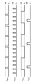
- V SNS1 and V SNS2 each indicate an example of the voltage of the sensor signal before the frequency is controlled by the frequency control unit 11, that is, the sensor signal output from the detection circuit 7.
- V DC1 indicates a voltage obtained by rectifying the voltage of the signal DC1, that is, the output voltage output from the phase AC1 of the generator 5.
- V SNS indicates the voltage of the sensor signal whose frequency is controlled by the frequency control unit 11.
- the cycle acquisition unit 12 obtains the cycle of the sensor signal whose frequency is controlled by the frequency control unit 11 as the sensor cycle T.
- the determination unit 13 performs the phase order determination process shown in FIG. 3 to determine the phase order of the phases AC1 to AC3 of the generator 5.
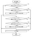
- FIG. 3 is a flowchart of the phase order determination process performed by the determination unit 13.
- FIG. 7 will be referred to as appropriate.
- V SNS indicates the voltage of the sensor signal whose frequency is controlled by the frequency control unit 11.
- V DC1 indicates a voltage obtained by rectifying the voltage of the signal DC1, that is, the output voltage output from the phase AC1 of the generator 5.
- V DC2 indicates a voltage obtained by rectifying the voltage of the signal DC2, that is, the output voltage output from the phase AC2 of the generator 5.
- V DC3 indicates a voltage obtained by rectifying the voltage of the signal DC3, that is, the output voltage output from the phase AC3 of the generator 5.
- the phase sequence of the generator 5 is AC1, AC2, and AC3.
- step S1 the determination unit 13 causes the cycle acquisition unit 12 to measure the sensor cycle T, and moves the process to step S2.
- step S2 the determination unit 13 obtains 1 / 3T and 2 / 3T by dividing the sensor period T by “3” equal to the number of phases of the generator 5, and moves the process to step S3.
- step S ⁇ b> 3 the determination unit 13 starts from 0 / 3T before the rising timing of the sensor signal whose frequency is controlled by the frequency control unit 11 (hereinafter referred to as “modulated sensor signal”). It is determined whether or not the signal DC1 has risen in the period up to 1 / 3T. Then, if it is determined that it has risen, the process proceeds to step S4, and if it is determined that it has not risen, the process proceeds to step S5.
- time t6 which is the rise timing of the modulated sensor signal
- the signal DC1 rises during a period from time t6 that is 0 / 3T before time t6 to time t5 that is 1 / 3T before time t6. That is, during the period from time t6 to t5, the output voltage output from the phase AC1 of the generator 5 is equal to or higher than a predetermined threshold voltage. For this reason, in the state shown in FIG. 7, it is determined that it has risen in step S3.
- step S ⁇ b> 4 the determination unit 13 performs a first process, which will be described later with reference to FIG. 4, and ends the phase order determination process illustrated in FIG. 3.
- step S5 the determination unit 13 determines whether the signal DC2 has risen in the period from 0 / 3T to 1 / 3T before the rise of the modulated sensor signal. Then, if it is determined that it has risen, the process proceeds to step S6. If it is determined that it has not risen, the process proceeds to step S7.
- step S6 the determination unit 13 performs a second process to be described later with reference to FIG. 5 and ends the phase sequence determination process illustrated in FIG.
- step S7 the determination unit 13 determines whether or not the signal DC3 has risen in a period from 0 / 3T to 1 / 3T before the rise of the modulated sensor signal. Then, if it is determined that it has risen, the process proceeds to step S8. If it is determined that it has not risen, the process proceeds to step S9.
- step S8 the determination unit 13 performs a third process, which will be described later with reference to FIG. 6, and ends the phase sequence determination process illustrated in FIG.
- step S9 the determination unit 13 performs an error process, and ends the phase order determination process shown in FIG.
- the generator 5 that is a three-phase AC generator
- any one of the signals DC1 to DC3 should rise every time 1 / 3T elapses.
- the processing shifts to step S9 means that all signals DC1 to DC3 rise in the period from 0 / 3T to 1 / 3T before the modulation sensor signal rises as a reference. That was not. For this reason, error processing is performed to notify that the phase order determination cannot be performed.
- FIG. 4 is a flowchart of the first process performed by the determination unit 13.
- step S11 the determination unit 13 determines whether or not the signal DC2 has risen in a period from 1 / 3T to 2 / 3T before the rise of the modulated sensor signal. Then, if it is determined that it has risen, the process proceeds to step S12. If it is determined that it has not risen, the process proceeds to step S14.
- step S12 the determination unit 13 determines whether or not the signal DC3 has risen in a period from 2 / 3T to 3 / 3T before the rise of the modulated sensor signal. Then, if it is determined that it has risen, the process proceeds to step S13. If it is determined that it has not risen, the process proceeds to step S17.
- step S13 the determination unit 13 determines that the phase sequence of the generator 5 is AC1, AC3, and AC2, and ends the first process illustrated in FIG.
- step S14 the determination unit 13 determines whether or not the signal DC3 has risen in the period from 1 / 3T to 2 / 3T before the rise of the modulated sensor signal. Then, if it is determined that it has risen, the process proceeds to step S15. If it is determined that it has not risen, the process proceeds to step S17.
- the signal DC3 rises during a period from time t5 that is 1 / 3T before time t6 to time t4 that is 2 / 3T before time t6. That is, during the period from time t5 to t4, the output voltage output from the phase AC3 of the generator 5 is equal to or higher than a predetermined threshold voltage. For this reason, in the state shown in FIG. 7, it will be determined that it has risen in step S14.
- step S ⁇ b> 15 the determination unit 13 determines whether the signal DC ⁇ b> 2 has risen in the period from 2/3 T to 3/3 T before the modulated sensor signal rise. To do. Then, if it is determined that it has risen, the process proceeds to step S16. If it is determined that it has not risen, the process proceeds to step S17.
- the signal DC2 rises during a period from time t4 that is 2 / 3T before time t6 to time t3 that is 3 / 3T before time t6. That is, during the period from time t4 to t3, the output voltage output from the phase AC2 of the generator 5 is equal to or higher than a predetermined threshold voltage. For this reason, in the state shown in FIG. 7, it is determined that it has risen in step S15.
- step S ⁇ b> 16 the determination unit 13 determines that the phase sequence of the generator 5 is AC ⁇ b> 1, AC ⁇ b> 2, AC ⁇ b> 3, and ends the first process illustrated in FIG. 4. In the state shown in FIG. 7 described above, it is determined that the phase sequence of the generator 5 is AC1, AC2, and AC3.
- step S ⁇ b> 17 the determination unit 13 performs error processing and ends the first processing illustrated in FIG. 4.
- FIG. 5 is a flowchart of the second process performed by the determination unit 13.
- step S21 the determination unit 13 determines whether or not the signal DC3 has risen in the period from 1 / 3T to 2 / 3T before the rise of the modulated sensor signal. Then, if it is determined that it has risen, the process proceeds to step S22. If it is determined that it has not risen, the process proceeds to step S24.
- step S22 the determination unit 13 determines whether or not the signal DC1 has risen in a period from 2 / 3T to 3 / 3T before the rise of the modulated sensor signal. Then, if it is determined that it has risen, the process proceeds to step S23. If it is determined that it has not risen, the process proceeds to step S27.
- step S23 the determination unit 13 determines that the phase sequence of the generator 5 is AC2, AC1, and AC3, and ends the second process illustrated in FIG.
- step S24 the determination unit 13 determines whether the signal DC1 has risen in the period from 1 / 3T to 2 / 3T before the rise of the modulated sensor signal. Then, if it is determined that it has risen, the process proceeds to step S25, and if it is determined that it has not risen, the process proceeds to step S27.
- step S25 the determination unit 13 determines whether or not the signal DC3 has risen in a period from 2 / 3T to 3 / 3T before the rise of the modulated sensor signal. Then, if it is determined that it has risen, the process proceeds to step S26, and if it is determined that it has not risen, the process proceeds to step S27.
- step S26 the determination unit 13 determines that the phase sequence of the generator 5 is AC2, AC3, and AC1, and ends the second process illustrated in FIG.
- step S27 as in steps S9 and S17 described above, the determination unit 13 performs error processing and ends the second processing illustrated in FIG.
- FIG. 6 is a flowchart of the third process performed by the determination unit 13.
- step S31 the determination unit 13 determines whether or not the signal DC1 has risen in the period from 1 / 3T to 2 / 3T before the rise of the modulated sensor signal. Then, if it is determined that it has risen, the process proceeds to step S32. If it is determined that it has not risen, the process proceeds to step S34.
- step S32 the determination unit 13 determines whether or not the signal DC2 has risen in a period from 2 / 3T to 3 / 3T before the rise of the modulated sensor signal. Then, if it is determined that it has risen, the process proceeds to step S33. If it is determined that it has not risen, the process proceeds to step S37.
- step S33 the determination unit 13 determines that the phase sequence of the generator 5 is AC3, AC2, and AC1, and ends the third process illustrated in FIG.
- step S34 the determination unit 13 determines whether or not the signal DC2 has risen in a period from 1 / 3T to 2 / 3T before the rise of the modulated sensor signal. Then, if it is determined that it has risen, the process proceeds to step S35, and if it is determined that it has not risen, the process proceeds to step S37.
- step S35 the determination unit 13 determines whether or not the signal DC1 has risen in the period from 2 / 3T to 3 / 3T before the rise of the modulated sensor signal. Then, if it is determined that it has risen, the process proceeds to step S36. If it is determined that it has not risen, the process proceeds to step S37.
- step S36 the determination unit 13 determines that the phase sequence of the generator 5 is AC3, AC1, and AC2, and ends the third process illustrated in FIG.
- step S37 as in steps S9, S17, and S27 described above, the determination unit 13 performs error processing, and ends the third processing illustrated in FIG.
- the determination unit 13 divides the sensor cycle T into three equal to the number of phases of the generator 5, and determines one of the signals DC1 to DC3 that rises in each divided period.
- the timing at which the voltage input from each of the input terminals IN1 to IN3 of the power generation control device 100 becomes equal to or higher than a predetermined threshold voltage is determined.
- the phases AC1 to AC3 of the generator 5 are connected to the input terminals IN1 to IN3 of the power generation control device 100, respectively. Therefore, as described above, the phase order of the phases AC1 to AC3 of the generator 5 is determined by determining the timing at which the voltage input from each of the input terminals IN1 to IN3 of the power generation control device 100 becomes equal to or higher than the threshold voltage. can do.
- the charging device AA determines the timing at which each of the signals DC1 to DC3 rises when the determination unit 13 determines the phase order of the phases AC1 to AC3 of the generator 5.
- the timing at which each of the signals DC1 to DC3 rises is also reversed as compared with the case where the generator 5 is normally rotated. Therefore, when the phase order of the phases AC1 to AC3 of the generator 5 is known in advance, it can be determined from the determination result by the determination unit 13 whether the generator 5 is rotating forward or reversely. .
- the charging device AA controls the switch elements Q1 to Q3 by the output supply control unit 14 according to the determination result by the determination unit 13. For this reason, even if each of the phases AC1 to AC3 of the generator 5 and each of the input terminals IN1 to IN3 of the power generation control device 100 are arbitrarily connected, the switch elements Q1 to Q3 according to the connection Can be appropriately supplied to the battery 6.
- charging device BB concerning a 2nd embodiment of the present invention is explained.
- the charging device BB is different from the charging device AA according to the first embodiment of the present invention shown in FIG. 1 in that a control circuit 1A is provided instead of the control circuit 1.
- the same components as those of the charging device AA are denoted by the same reference numerals, and the description thereof is omitted.
- the control circuit 1A is different from the control circuit 1 in that a determination unit 13A is provided instead of the determination unit 13. Similarly to the determination unit 13, the determination unit 13A determines the phase order of the phases AC1 to AC3 of the generator 5. However, when determining the phase sequence of the phases AC1 to AC3 of the generator 5, the determination unit 13 performs the phase sequence determination process illustrated in FIG. 3, whereas the determination unit 13A includes the phase sequence illustrated in FIG. The difference is that the order determination process is performed.
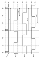
- FIG. 8 is a flowchart of the phase order determination process performed by the determination unit 13A.
- FIG. 9 will be referred to as appropriate.
- the phase sequence of the generator 5 is AC1, AC2, and AC3.
- the signal DC1 rises immediately before the reference time t6
- the signal DC1 rises immediately after the reference time t16.
- the reason why the rise of the signal DC1 is delayed is that, for example, the operation of the generator 5 has changed and the sensor cycle T has suddenly changed, or the measurement error of the voltage V SNS or the voltage V DC1 has occurred. ,Conceivable.
- the determination unit 13A performs steps S1, S2, S4, S6, S8, and S9 of FIG. 3 performed by the determination unit 13 in steps S101, S102, S104, S106, S108, and S109, respectively. Similar processing is performed.
- step S103 the determination unit 13A uses the timing at which the modulated sensor signal rises as a reference for a period from 0 / 3T to 1 / 3T, or from 3 / 3T to 4 / 3T. It is determined whether or not the signal DC1 has risen. Then, if it is determined that it has risen, the process proceeds to step S104. If it is determined that it has not risen, the process proceeds to step S105.
- time t16 which is the rise timing of the modulated sensor signal
- time t15 which is 1 / 3T before time t16
- none of the signals DC1 to DC3 rises.
- the signal DC1 rises during a period from time t13, which is 3 / 3T before time t16, to time t12, which is 4 / 3T before time t16. For this reason, in the state shown in FIG. 9, it is determined that the operation has started in step S ⁇ b> 103.
- step S105 the determination unit 13A uses the timing at which the modulated sensor signal rises as a reference, a period from 0 / 3T to 1 / 3T, or a period from 3 / 3T to 4 / 3T. Thus, it is determined whether or not the signal DC2 rises. Then, if it is determined that it has risen, the process proceeds to step S106. If it is determined that it has not risen, the process proceeds to step S107.
- step S107 the determination unit 13A uses the timing at which the modulated sensor signal rises as a reference, a period from 0 / 3T to 1 / 3T, or a period from 3 / 3T to 4 / 3T. Thus, it is determined whether or not the signal DC3 rises. Then, if it is determined that it has risen, the process proceeds to step S108. If it is determined that it has not risen, the process proceeds to step S109.
- the battery 6 is applied as a load to which power is supplied from the generator 5, but the present invention is not limited to this.
- the generator 5 has three phases. However, the present invention is not limited to this. For example, the generator 5 may have two phases or four phases.
- the determination unit 13 and the determination unit 13A divide the sensor cycle T by a number equal to the number of phases of the generator 5, but the present invention is not limited to this.
- the generator 5 has p phases (where p is an integer satisfying p ⁇ 2)
- the sensor cycle T may be divided by q.
- q is a number satisfying q ⁇ p, and may be an integer or a decimal.
- the drive circuit 30 performs PWM control of the switch elements Q1 to Q3.
- the drive circuit 30 is not limited to this and may be, for example, phase controlled.
- the determination unit 13 and the determination unit 13A determine the phase order of the generator 5 based on whether or not each of the signals DC1 to DC3 has risen.
- the present invention is not limited to this.
- the determination may be made based on whether or not each of the signals DC1 to DC3 has fallen. Further, it may be determined by combining both of whether the signals DC1 to DC3 have risen and whether they have fallen.
- Control circuit 5 Generator 6: Battery 7: Detection circuit 8: Fuse 11: Frequency control part 12: Period acquisition part 13, 13A: Determination part 14: Output supply control part 20: Zero cross signal generation circuit 30: Drive circuit 100: Power generation control device Q1-Q3: Switch element AA, BB: Charging device AC1-AC3: Phase
Landscapes
- Engineering & Computer Science (AREA)
- Power Engineering (AREA)
- Physics & Mathematics (AREA)
- General Physics & Mathematics (AREA)
- Control Of Eletrric Generators (AREA)
- Supply And Distribution Of Alternating Current (AREA)
- Heterocyclic Carbon Compounds Containing A Hetero Ring Having Oxygen Or Sulfur (AREA)
Priority Applications (4)
| Application Number | Priority Date | Filing Date | Title |
|---|---|---|---|
| DE201211005304 DE112012005304T5 (de) | 2012-03-30 | 2012-12-25 | Steuer-/Regelschaltung sowie eine solche aufweisende Stromerzeugungsvorrichtung |
| GB1411501.8A GB2512236B (en) | 2012-03-30 | 2012-12-25 | Control circuit, and power generation device having the same |
| US14/369,693 US9285410B2 (en) | 2012-03-30 | 2012-12-25 | Control circuit, and power generation device having the same |
| JP2013537722A JP5405698B1 (ja) | 2012-03-30 | 2012-12-25 | 制御回路、および制御回路を備える発電装置 |
Applications Claiming Priority (2)
| Application Number | Priority Date | Filing Date | Title |
|---|---|---|---|
| JP2012079585 | 2012-03-30 | ||
| JP2012-079585 | 2012-03-30 |
Publications (1)
| Publication Number | Publication Date |
|---|---|
| WO2013145484A1 true WO2013145484A1 (ja) | 2013-10-03 |
Family
ID=49258813
Family Applications (1)
| Application Number | Title | Priority Date | Filing Date |
|---|---|---|---|
| PCT/JP2012/083506 Ceased WO2013145484A1 (ja) | 2012-03-30 | 2012-12-25 | 制御回路、および制御回路を備える発電装置 |
Country Status (6)
| Country | Link |
|---|---|
| US (1) | US9285410B2 (it) |
| JP (1) | JP5405698B1 (it) |
| DE (1) | DE112012005304T5 (it) |
| GB (1) | GB2512236B (it) |
| IT (1) | ITTO20130177A1 (it) |
| WO (1) | WO2013145484A1 (it) |
Cited By (2)
| Publication number | Priority date | Publication date | Assignee | Title |
|---|---|---|---|---|
| CN103558489A (zh) * | 2013-10-18 | 2014-02-05 | 无锡锡洲电磁线有限公司 | 用于换位导线的自动检测装置 |
| JP2024106804A (ja) * | 2023-01-27 | 2024-08-08 | 株式会社豊田自動織機 | 電力変換装置 |
Families Citing this family (4)
| Publication number | Priority date | Publication date | Assignee | Title |
|---|---|---|---|---|
| CA3171621A1 (en) * | 2020-03-17 | 2021-09-23 | Takamasa YAMAZAKI | Control unit |
| CN111707879A (zh) * | 2020-05-14 | 2020-09-25 | 上海二十冶建设有限公司 | 利用双电源在线核相检测装置对发电机并网核相的方法 |
| CN112271719A (zh) * | 2020-09-18 | 2021-01-26 | 北京潞电电气设备有限公司 | 一种发电机控制器 |
| DE102021129346A1 (de) | 2021-11-11 | 2023-05-11 | Seg Automotive Germany Gmbh | Zusatzbeschaltung für einen Spannungsregler, Spannungsregler und Verfahren zum Betreiben einer Generatoreinheit |
Citations (5)
| Publication number | Priority date | Publication date | Assignee | Title |
|---|---|---|---|---|
| JPS587569A (ja) * | 1981-06-30 | 1983-01-17 | エレベ−タ−・ゲ−エムベ−ハ− | 3相回路網の相順序監視方法及び回路 |
| JP2002027757A (ja) * | 2000-07-06 | 2002-01-25 | Meidensha Corp | 電源位相検出回路 |
| JP2007221850A (ja) * | 2006-02-14 | 2007-08-30 | Matsushita Electric Ind Co Ltd | 三相電動機の位相切換え装置 |
| JP2008061322A (ja) * | 2006-08-30 | 2008-03-13 | Hitachi Appliances Inc | 三相コンバータ・インバータ装置及びモジュール |
| WO2010073593A1 (ja) * | 2008-12-22 | 2010-07-01 | 新電元工業株式会社 | バッテリ充電装置 |
Family Cites Families (5)
| Publication number | Priority date | Publication date | Assignee | Title |
|---|---|---|---|---|
| US20070063664A1 (en) * | 2005-09-22 | 2007-03-22 | Avistar, Inc. | Phase identification apparatus having automatic gain control to prevent detector saturation |
| JP5233239B2 (ja) * | 2007-10-19 | 2013-07-10 | 国産電機株式会社 | 発電装置 |
| JP5160934B2 (ja) * | 2008-03-28 | 2013-03-13 | 新電元工業株式会社 | バッテリ充電装置、バッテリ充電制御方法 |
| JP5283259B2 (ja) | 2008-09-19 | 2013-09-04 | 本田技研工業株式会社 | 発電制御装置 |
| CN102680806A (zh) * | 2012-04-20 | 2012-09-19 | 京东方科技集团股份有限公司 | 一种三相交流电相序检测方法及装置 |
-
2012
- 2012-12-25 JP JP2013537722A patent/JP5405698B1/ja active Active
- 2012-12-25 WO PCT/JP2012/083506 patent/WO2013145484A1/ja not_active Ceased
- 2012-12-25 GB GB1411501.8A patent/GB2512236B/en active Active
- 2012-12-25 US US14/369,693 patent/US9285410B2/en active Active
- 2012-12-25 DE DE201211005304 patent/DE112012005304T5/de not_active Ceased
-
2013
- 2013-03-05 IT ITTO20130177 patent/ITTO20130177A1/it unknown
Patent Citations (5)
| Publication number | Priority date | Publication date | Assignee | Title |
|---|---|---|---|---|
| JPS587569A (ja) * | 1981-06-30 | 1983-01-17 | エレベ−タ−・ゲ−エムベ−ハ− | 3相回路網の相順序監視方法及び回路 |
| JP2002027757A (ja) * | 2000-07-06 | 2002-01-25 | Meidensha Corp | 電源位相検出回路 |
| JP2007221850A (ja) * | 2006-02-14 | 2007-08-30 | Matsushita Electric Ind Co Ltd | 三相電動機の位相切換え装置 |
| JP2008061322A (ja) * | 2006-08-30 | 2008-03-13 | Hitachi Appliances Inc | 三相コンバータ・インバータ装置及びモジュール |
| WO2010073593A1 (ja) * | 2008-12-22 | 2010-07-01 | 新電元工業株式会社 | バッテリ充電装置 |
Cited By (2)
| Publication number | Priority date | Publication date | Assignee | Title |
|---|---|---|---|---|
| CN103558489A (zh) * | 2013-10-18 | 2014-02-05 | 无锡锡洲电磁线有限公司 | 用于换位导线的自动检测装置 |
| JP2024106804A (ja) * | 2023-01-27 | 2024-08-08 | 株式会社豊田自動織機 | 電力変換装置 |
Also Published As
| Publication number | Publication date |
|---|---|
| US20140368187A1 (en) | 2014-12-18 |
| GB2512236B (en) | 2017-01-18 |
| JPWO2013145484A1 (ja) | 2015-12-10 |
| JP5405698B1 (ja) | 2014-02-05 |
| DE112012005304T5 (de) | 2014-11-20 |
| US9285410B2 (en) | 2016-03-15 |
| GB2512236A (en) | 2014-09-24 |
| ITTO20130177A1 (it) | 2013-10-01 |
| GB201411501D0 (en) | 2014-08-13 |
Similar Documents
| Publication | Publication Date | Title |
|---|---|---|
| JP5405698B1 (ja) | 制御回路、および制御回路を備える発電装置 | |
| EP3364538A1 (en) | Ac rotating machine control device and electric power steering device equipped with same | |
| JP4936974B2 (ja) | 電力開閉制御装置 | |
| CN105048851A (zh) | 电力转换装置、控制装置及电力转换装置的控制方法 | |
| WO2012026535A1 (ja) | 電力変換装置 | |
| JP6391897B1 (ja) | 直列多重インバータ | |
| WO2016132427A1 (ja) | 電力変換装置 | |
| JP2016048997A (ja) | 電力変換装置の制御方法とその装置 | |
| JPWO2017168522A1 (ja) | 電力変換装置 | |
| KR101529889B1 (ko) | 역률개선 기능이 구비된 수배전반 | |
| EP2892145B1 (en) | Power converter and inverter device equipped with same | |
| JP5758941B2 (ja) | 計測装置、計測方法、およびプログラム | |
| JP6303334B2 (ja) | 電力変換装置のデッドタイム補償装置 | |
| JP5652454B2 (ja) | 電力変換装置 | |
| JP5405697B1 (ja) | 制御回路、および制御回路を備える発電装置 | |
| US20170274926A1 (en) | Power conversion device, control method for same, and electric power steering control device | |
| JP5707028B2 (ja) | 電力変換装置 | |
| JP5724103B2 (ja) | 誘導電動機制御装置及び誘導電動機制御方法 | |
| Brychcín et al. | Modulator for 4-level flying capacitor converter with balancing control in the closed loop | |
| KR101298503B1 (ko) | 3상 인버터의 불균형 전압 보상 회로 및 방법 | |
| JP6264913B2 (ja) | 電力変換装置の制御装置および電力変換システム | |
| JP6547524B2 (ja) | 多相電力変換器の制御方法及び多相電力変換器 | |
| JP2014143049A (ja) | 励磁突入電流抑制装置 | |
| JP2015023777A (ja) | 高圧インバータの2段変化防止装置 | |
| WO2013150692A1 (ja) | 制御回路、および制御回路を備える発電装置 |
Legal Events
| Date | Code | Title | Description |
|---|---|---|---|
| ENP | Entry into the national phase |
Ref document number: 2013537722 Country of ref document: JP Kind code of ref document: A |
|
| 121 | Ep: the epo has been informed by wipo that ep was designated in this application |
Ref document number: 12872995 Country of ref document: EP Kind code of ref document: A1 |
|
| ENP | Entry into the national phase |
Ref document number: 1411501 Country of ref document: GB Kind code of ref document: A Free format text: PCT FILING DATE = 20121225 |
|
| WWE | Wipo information: entry into national phase |
Ref document number: 1411501.8 Country of ref document: GB |
|
| WWE | Wipo information: entry into national phase |
Ref document number: 14369693 Country of ref document: US |
|
| WWE | Wipo information: entry into national phase |
Ref document number: 1120120053044 Country of ref document: DE Ref document number: 112012005304 Country of ref document: DE |
|
| 122 | Ep: pct application non-entry in european phase |
Ref document number: 12872995 Country of ref document: EP Kind code of ref document: A1 |