WO2013145485A1 - Dispositif de traitement d'informations - Google Patents
Dispositif de traitement d'informations Download PDFInfo
- Publication number
- WO2013145485A1 WO2013145485A1 PCT/JP2012/083538 JP2012083538W WO2013145485A1 WO 2013145485 A1 WO2013145485 A1 WO 2013145485A1 JP 2012083538 W JP2012083538 W JP 2012083538W WO 2013145485 A1 WO2013145485 A1 WO 2013145485A1
- Authority
- WO
- WIPO (PCT)
- Prior art keywords
- display
- contact
- display area
- information processing
- processing apparatus
- Prior art date
- Legal status (The legal status is an assumption and is not a legal conclusion. Google has not performed a legal analysis and makes no representation as to the accuracy of the status listed.)
- Ceased
Links
Images




Classifications
-
- G—PHYSICS
- G06—COMPUTING OR CALCULATING; COUNTING
- G06F—ELECTRIC DIGITAL DATA PROCESSING
- G06F3/00—Input arrangements for transferring data to be processed into a form capable of being handled by the computer; Output arrangements for transferring data from processing unit to output unit, e.g. interface arrangements
- G06F3/01—Input arrangements or combined input and output arrangements for interaction between user and computer
- G06F3/048—Interaction techniques based on graphical user interfaces [GUI]
- G06F3/0487—Interaction techniques based on graphical user interfaces [GUI] using specific features provided by the input device, e.g. functions controlled by the rotation of a mouse with dual sensing arrangements, or of the nature of the input device, e.g. tap gestures based on pressure sensed by a digitiser
- G06F3/0488—Interaction techniques based on graphical user interfaces [GUI] using specific features provided by the input device, e.g. functions controlled by the rotation of a mouse with dual sensing arrangements, or of the nature of the input device, e.g. tap gestures based on pressure sensed by a digitiser using a touch-screen or digitiser, e.g. input of commands through traced gestures
-
- G—PHYSICS
- G06—COMPUTING OR CALCULATING; COUNTING
- G06F—ELECTRIC DIGITAL DATA PROCESSING
- G06F9/00—Arrangements for program control, e.g. control units
- G06F9/06—Arrangements for program control, e.g. control units using stored programs, i.e. using an internal store of processing equipment to receive or retain programs
- G06F9/44—Arrangements for executing specific programs
- G06F9/451—Execution arrangements for user interfaces
Definitions
- the present invention relates to an information processing apparatus for displaying information, a display method, and a program.
- the screen moves in the direction of movement of the finger, or if the finger touches the display is moved, the screen is enlarged.
- the information terminal device responds to finger movements such as sliding the displayed information horizontally or vertically, or displaying the previous page or the next page of the displayed page. To change the display. That is, only the content displayed in one display area changes, and the display area of the displayed information does not change.
- An object of the present invention is to provide an information processing apparatus, a display method, and a program that solve the above-described problems.
- the information processing apparatus of the present invention A display unit having a plurality of display areas and having a touch panel function; A control unit that activates an application corresponding to the icon displayed at the position where the display unit detects contact, and causes the display to display in the display area corresponding to the moving direction of the contact.
- the display method of the present invention includes: Detecting a contact with a display unit having a plurality of display areas; Starting an application corresponding to the icon displayed at the position where the contact is detected; Determining a display area to be displayed by the activated application based on the detected moving direction of the contact; Performing the display in the determined display area.
- the program of the present invention is A program for causing an information processing apparatus including a display unit having a plurality of display areas to execute, A procedure for detecting contact with the display unit; A procedure for starting an application corresponding to an icon displayed at the position where the contact is detected; A procedure for determining a display area to be displayed by the activated application based on the detected moving direction of the contact; And a step of performing the display in the determined display area.
- the user can select the display area of the application as desired.
- FIG. 1 It is a figure which shows one Embodiment of the information processing apparatus of this invention. It is a figure which shows an example of the external appearance structure of the information processing apparatus shown in FIG. 3 is a flowchart for explaining a display method in the information processing apparatus shown in FIG. 1. It is a figure which shows an example of the display in a display part when the contact which a display part moves to the right is detected. It is a figure which shows an example of the display in a display part when the contact which a display part moves to the left is detected. It is a figure which shows an example of the display in a display part when the contact which a display part moves upwards is detected.
- FIG. 1 is a diagram showing an embodiment of an information processing apparatus according to the present invention.
- the information processing apparatus 100 includes a display unit 110 and a control unit 120.
- the display unit 110 is a display that displays information.
- the display unit 110 has a plurality of display areas. This display area may be one where a single display is physically divided into a plurality of areas, and each of the divided areas may be used, or each of a plurality of physically separated displays.
- the display unit 110 has a touch panel function, and detects contact of a contact body such as a finger or a pen.
- the control unit 120 controls the information processing apparatus 100 as a whole.
- the control unit 120 displays an icon of a preset application at a predetermined position on the display unit 110.
- the control part 120 starts the application according to the icon currently displayed in the position where the display part 110 detected the contact.
- the control unit 120 causes the display area corresponding to the moving direction of the contact detected by the display unit 110 to display the activated application. Details of the method of determining the display area according to the moving direction will be described later.
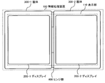
- FIG. 2 is a diagram showing an example of an external structure of the information processing apparatus 100 shown in FIG.
- FIG. 2 illustrates an example in which the information processing apparatus 100 includes two casings and each display disposed in each casing is used as a display area.
- the information processing apparatus 100 shown in FIG. 1 includes two casings 300-1 and 300-2 connected by a hinge part 400, and can be opened and closed around the hinge part 400. It has become.
- a display 200-1 that is one display area is disposed in the housing 300-1
- a display 200-2 that is the other display area is disposed in the housing 300-2.
- the display unit 110 includes the display 200-1 and the display 200-2.
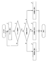
- FIG. 3 is a flowchart for explaining a display method in the information processing apparatus 100 shown in FIG.
- step 1 the control unit 120 displays a preset application icon at a predetermined position on the display unit 110.
- This display method may be a general one.
- step 3 the direction of the flick, that is, the detected moving direction of the contact, is which direction. Is determined by the control unit 120.
- flick refers to a contact operation in which the user receives an icon on the display unit 110 with a finger or the like.
- the control unit 120 determines the display area (right screen) arranged on the right side of the display area as a display area to be displayed by the application to be activated. To do. In step 4, the control unit 120 causes the determined display area (right screen) to display the application to be started.
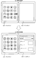
- FIG. 4 is a diagram illustrating an example of display on the display unit 110 when the display unit 110 detects a contact moving to the right.
- the user makes contact with a desired icon (in this case, the browser icon in FIG. 4). If the contact is a flick that moves to the right, the browser screen is displayed on the display 200-2, which is the display area on the right side, as shown in the lower diagram of FIG.
- the control unit 120 causes the display area (left screen) arranged on the left side of the display area to be displayed by the application to be activated. Determine as. In step 5, the control unit 120 causes the determined display area (left screen) to display the application to be started.
- FIG. 5 is a diagram illustrating an example of display on the display unit 110 when the display unit 110 detects a contact moving to the left.
- the user makes contact with a desired icon (in this case, the browser icon in FIG. 5). If the contact is a flick that moves to the left, the browser screen is displayed on the display 200-1, which is the display area where the contact is detected, as shown in the lower diagram of FIG.
- control unit 120 determines the entire two display areas (full screen) as display areas for display by the application to be activated. In step 6, the control unit 120 causes the determined display area (full screen) to be displayed by the application to be activated.
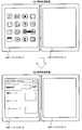
- FIG. 6 is a diagram illustrating an example of display on the display unit 110 when the display unit 110 detects a contact moving upward.
- the user makes contact with a desired icon (in this case, the browser icon in FIG. 6).
- a desired icon in this case, the browser icon in FIG. 6
- the contact is a flick that moves upward
- a browser screen is displayed on the entire display 200-1, 200-1 as shown in the lower diagram of FIG.
- the same processing may also be performed when the display unit 110 detects a contact that moves downward.
- the icon of the application is displayed on the display 200-1 which is the left display area (left screen) has been described above as an example.
- the display 200 where the icon is the right display area (right screen). -2 may be displayed.
- the method for determining the display area for display by the application is the same as described above.
- the control unit 120 has a display area (for example, the display 200-) different from the display area (for example, the display 200-1) that includes the position where the contact is detected in the movement direction of the contact detected by the display unit 110. 2) If there is, display by the application in the display area (for example, display 200-2). In addition, the control unit 120 may display another display area in a direction opposite to the movement direction when there is no other display area (for example, the display 200-2) in the movement direction of the contact detected by the display unit 110. When there is (for example, the display 200-2), the display area (for example, the display 200-1) including the position where the contact is detected is displayed by the application. In addition, when there is no other display area (for example, the display 200-2) in the direction of movement of the contact detected by the display unit 110 and the direction opposite to the movement direction, the control unit 120 (for example, the display 200- 1, 200-2) display by application.
- the display area for example, the display 200- 1, 200-2
- the display area in which the display by the activated application is performed is a display area on the side where the icon displayed for allowing the user to select activation of the application is displayed.
- the user can select the display area in which the display by the activated application is performed in the flick direction. Thereby, the user can select the display area of the application as desired.
- the information processing apparatus 100 is configured by two casings 300-1 and 300-2, and the displays 200-1 and 200-2 are disposed in the casings 300-1 and 300-2, respectively.
- the information processing apparatus may be configured by a single casing, and the displays 200-1 and 200-2 may be disposed in the casing.
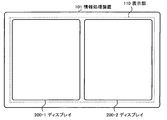
- FIG. 7 is a diagram illustrating an example of an external structure of an information processing apparatus that is configured by one casing and in which two displays are arranged in the casing.
- the information processing apparatus 101 is composed of a single casing and includes displays 200-1 and 200-2 that are two display areas.
- the display method by the application on the displays 200-1 and 200-2 is the same as described above.
- the information processing apparatus may be configured by one casing, and one display unit may be physically divided into two display areas.
- FIG. 8 is a diagram illustrating an example of an external structure of an information processing apparatus that is configured by one housing and in which one display unit is physically divided into two display areas.
- the information processing apparatus 102 is composed of one housing, and one display unit 111 is physically divided into two display areas 500-1 and 500-2.
- the display areas 500-1 and 500-2 are predetermined by setting of software or the like.
- the display method by the application in the display areas 500-1 and 500-2 is the same as the display method on the displays 200-1 and 200-2 described above.
- FIG. 9 is a diagram showing an example of the external structure of an information processing apparatus provided with four display areas.
- the information processing apparatus 103 includes four casings 300-1 to 300-4 connected to each other by hinges or the like, and each of the casings 300-1 to 300-4 includes a display unit 112. A plurality of displays 200-1 to 200-4, which are display areas, are arranged.
- a browser icon is displayed on the display 200-3 as shown in FIG.
- the control unit 120 activates the browser, and moves the activated browser screen in the direction “A”. It is displayed on the arranged display 200-1.
- the control unit 120 activates the browser and displays the screen of the activated browser on the entire displays 200-1 to 200-4.
- the control unit 120 activates the browser, and the screen of the activated browser is arranged in the direction “C”. Displayed on the display 200-4.
- the control unit 120 activates the browser and displays the screen of the activated browser on its display 200-3.
- the control unit 120 activates the browser, and the screen of the activated browser is arranged in the direction “E”. Display on the display 200-2.
- the control unit 120 activates the browser.
- the screen of the activated browser may be displayed on the entire display 200-1 to 200-4.
- the control unit 120 activates the browser and arranges the activated browser screen in that direction as described above.
- the control unit 120 activates the browser and displays the activated browser screen on the display including the position where the contact is detected.
- “tapping” refers to an operation in which the user taps the surface of the display unit 112 with a finger or the like.
- the detected movement direction of the contact may be determined by determining a direction close to the vertical direction or the horizontal direction with respect to the opposite sides of the plurality of display areas, and setting the close direction as the movement direction. Further, when there is an oblique moving direction as shown in FIG. 9, the moving direction may be determined using information on an angle of 45 degrees from the vertical direction or the horizontal direction.
- touch panel functions that detect not only contact but also proximity of an object and perform processing according to the position where proximity is detected.
- the present invention is also applicable to an apparatus having a touch panel function for detecting such proximity.
- the processing performed by each component provided in the information processing apparatuses 100 to 103 described above may be performed by a logic circuit that is produced according to the purpose.
- a computer program (hereinafter referred to as a program) in which processing contents are described as a procedure is recorded on a recording medium readable by the information processing apparatuses 100 to 103, and the program recorded on the recording medium is stored in the information processing apparatuses 100 to 103.
- the program may be read by 103 and executed.
- Recording media that can be read by the information processing apparatuses 100 to 103 include transferable recording media such as floppy (registered trademark) disks, magneto-optical disks, DVDs, and CDs, as well as built-in information processing apparatuses 100 to 103.
- the program recorded on the recording medium is read by the control unit 120 provided in the information processing apparatuses 100 to 103, and the same processing as described above is performed under the control of the control unit 120.
- the control unit 120 operates as a computer that executes a program read from a recording medium on which the program is recorded.
- a part or all of the above embodiment can be described as in the following supplementary notes, but is not limited thereto.
- Appendix 1 A display unit having a plurality of display areas and having a touch panel function;
- An information processing apparatus comprising: a control unit that activates an application corresponding to an icon displayed at a position where the display unit detects contact, and causes the display area to display according to the moving direction of the contact.
- the control unit depends on the application in the second display area.
- the information processing apparatus according to appendix 1, wherein display is performed.
- the control unit When the second display area is not present in the movement direction and the second display area is present in a direction opposite to the movement direction, the control unit includes the first display area.
- the display by the application is performed, and when there is no second display area in the movement direction and the direction opposite to the movement direction, the display by the application is performed over the plurality of display areas.
- the information processing apparatus according to 2. (Supplementary note 4) Any one of Supplementary notes 1 to 3, wherein the display unit includes a plurality of physically separated displays, and each of the plurality of display areas is each of the plurality of displays.
- the information processing apparatus according to item 1.
- An information processing apparatus including a display unit having a plurality of display areas, A procedure for detecting contact with the display unit; A procedure for starting an application corresponding to an icon displayed at the position where the contact is detected; A procedure for determining a display area to be displayed by the activated application based on the detected moving direction of the contact; A program for executing the procedure for performing the display in the determined display area.
Landscapes
- Engineering & Computer Science (AREA)
- Software Systems (AREA)
- Theoretical Computer Science (AREA)
- General Engineering & Computer Science (AREA)
- Human Computer Interaction (AREA)
- Physics & Mathematics (AREA)
- General Physics & Mathematics (AREA)
- User Interface Of Digital Computer (AREA)
Applications Claiming Priority (2)
| Application Number | Priority Date | Filing Date | Title |
|---|---|---|---|
| JP2012-076584 | 2012-03-29 | ||
| JP2012076584 | 2012-03-29 |
Publications (1)
| Publication Number | Publication Date |
|---|---|
| WO2013145485A1 true WO2013145485A1 (fr) | 2013-10-03 |
Family
ID=49258814
Family Applications (1)
| Application Number | Title | Priority Date | Filing Date |
|---|---|---|---|
| PCT/JP2012/083538 Ceased WO2013145485A1 (fr) | 2012-03-29 | 2012-12-26 | Dispositif de traitement d'informations |
Country Status (2)
| Country | Link |
|---|---|
| JP (1) | JPWO2013145485A1 (fr) |
| WO (1) | WO2013145485A1 (fr) |
Cited By (3)
| Publication number | Priority date | Publication date | Assignee | Title |
|---|---|---|---|---|
| GB2519124A (en) * | 2013-10-10 | 2015-04-15 | Ibm | Controlling application launch |
| JP2015132965A (ja) * | 2014-01-14 | 2015-07-23 | レノボ・シンガポール・プライベート・リミテッド | 複数のディスプレイに対するアプリケーション画像の表示方法、電子機器およびコンピュータ・プログラム |
| WO2024241496A1 (fr) * | 2023-05-23 | 2024-11-28 | 日産自動車株式会社 | Procédé d'affichage, dispositif d'affichage et système d'affichage |
Citations (3)
| Publication number | Priority date | Publication date | Assignee | Title |
|---|---|---|---|---|
| JP2010092340A (ja) * | 2008-10-09 | 2010-04-22 | Sharp Corp | 画像表示/像検知装置、画像表示方法、画像表示プログラムおよび当該プログラムを記録した記録媒体 |
| US20110154248A1 (en) * | 2009-12-22 | 2011-06-23 | Junya Tsuruoka | Information processing apparatus and screen selection method |
| WO2011135894A1 (fr) * | 2010-04-27 | 2011-11-03 | 日本電気株式会社 | Terminal de traitement d'informations et son procédé de commande |
-
2012
- 2012-12-26 JP JP2014507334A patent/JPWO2013145485A1/ja active Pending
- 2012-12-26 WO PCT/JP2012/083538 patent/WO2013145485A1/fr not_active Ceased
Patent Citations (3)
| Publication number | Priority date | Publication date | Assignee | Title |
|---|---|---|---|---|
| JP2010092340A (ja) * | 2008-10-09 | 2010-04-22 | Sharp Corp | 画像表示/像検知装置、画像表示方法、画像表示プログラムおよび当該プログラムを記録した記録媒体 |
| US20110154248A1 (en) * | 2009-12-22 | 2011-06-23 | Junya Tsuruoka | Information processing apparatus and screen selection method |
| WO2011135894A1 (fr) * | 2010-04-27 | 2011-11-03 | 日本電気株式会社 | Terminal de traitement d'informations et son procédé de commande |
Cited By (4)
| Publication number | Priority date | Publication date | Assignee | Title |
|---|---|---|---|---|
| GB2519124A (en) * | 2013-10-10 | 2015-04-15 | Ibm | Controlling application launch |
| US10761717B2 (en) | 2013-10-10 | 2020-09-01 | International Business Machines Corporation | Controlling application launch |
| JP2015132965A (ja) * | 2014-01-14 | 2015-07-23 | レノボ・シンガポール・プライベート・リミテッド | 複数のディスプレイに対するアプリケーション画像の表示方法、電子機器およびコンピュータ・プログラム |
| WO2024241496A1 (fr) * | 2023-05-23 | 2024-11-28 | 日産自動車株式会社 | Procédé d'affichage, dispositif d'affichage et système d'affichage |
Also Published As
| Publication number | Publication date |
|---|---|
| JPWO2013145485A1 (ja) | 2015-12-10 |
Similar Documents
| Publication | Publication Date | Title |
|---|---|---|
| JP6054892B2 (ja) | 複数のディスプレイに対するアプリケーション画像の表示方法、電子機器およびコンピュータ・プログラム | |
| JP6381032B2 (ja) | 電子機器、その制御方法及びプログラム | |
| CN101315593B (zh) | 触控式移动运算装置与应用于其上的触控方法 | |
| JP4865063B2 (ja) | 情報処理装置、情報処理方法およびプログラム | |
| CN103197848A (zh) | 用于在电子装置中执行电子书阅读应用的系统和方法 | |
| JP6319298B2 (ja) | 情報端末、表示制御方法及びそのプログラム | |
| JP2011022842A (ja) | 表示装置、表示方法及びプログラム | |
| CN103955331A (zh) | 一种应用程序图标的显示处理方法及装置 | |
| JP5846129B2 (ja) | 情報処理端末およびその制御方法 | |
| JP2016528600A (ja) | グラフィカルユーザインターフェースの一部分の選択方法 | |
| CN103197876A (zh) | 在有电子书阅读器功能的终端中显示电子书的方法和装置 | |
| JP2011248465A (ja) | 情報処理装置および表示制御方法 | |
| EP2975508A1 (fr) | Commande d'affichage | |
| WO2013145485A1 (fr) | Dispositif de traitement d'informations | |
| JP6365529B2 (ja) | 端末装置、情報表示方法及びプログラム | |
| JP6096100B2 (ja) | 電子機器、制御方法、及び制御プログラム | |
| US9213555B2 (en) | Off-screen window controls | |
| JP2021182405A (ja) | 電子機器及びコンテンツ表示プログラム | |
| JP2013228786A (ja) | 情報端末、情報表示方法及びプログラム | |
| CN103577495A (zh) | 浏览器的手势操作方法及装置 | |
| JP6127401B2 (ja) | 情報処理装置、プログラム及び情報処理方法 | |
| JP2021184269A (ja) | ユーザインターフェース処理プログラム、記録媒体、ユーザインターフェース処理方法 | |
| JP6661421B2 (ja) | 情報処理装置、制御方法、及びプログラム | |
| KR101268141B1 (ko) | 자모 변환 기반의 터치스크린 한글 입력방법, 장치 및 이를 이용하는 전자 기기 | |
| JP2014160301A (ja) | 情報処理装置、情報処理方法およびプログラム |
Legal Events
| Date | Code | Title | Description |
|---|---|---|---|
| 121 | Ep: the epo has been informed by wipo that ep was designated in this application |
Ref document number: 12872346 Country of ref document: EP Kind code of ref document: A1 |
|
| ENP | Entry into the national phase |
Ref document number: 2014507334 Country of ref document: JP Kind code of ref document: A |
|
| NENP | Non-entry into the national phase |
Ref country code: DE |
|
| 122 | Ep: pct application non-entry in european phase |
Ref document number: 12872346 Country of ref document: EP Kind code of ref document: A1 |