WO2013145542A1 - Thermomètre clinique électronique et son procédé de commande - Google Patents
Thermomètre clinique électronique et son procédé de commande Download PDFInfo
- Publication number
- WO2013145542A1 WO2013145542A1 PCT/JP2013/001057 JP2013001057W WO2013145542A1 WO 2013145542 A1 WO2013145542 A1 WO 2013145542A1 JP 2013001057 W JP2013001057 W JP 2013001057W WO 2013145542 A1 WO2013145542 A1 WO 2013145542A1
- Authority
- WO
- WIPO (PCT)
- Prior art keywords
- electronic thermometer
- temperature measurement
- body temperature
- mode
- current consumption
- Prior art date
- Legal status (The legal status is an assumption and is not a legal conclusion. Google has not performed a legal analysis and makes no representation as to the accuracy of the status listed.)
- Ceased
Links
Images


Classifications
-
- G—PHYSICS
- G01—MEASURING; TESTING
- G01K—MEASURING TEMPERATURE; MEASURING QUANTITY OF HEAT; THERMALLY-SENSITIVE ELEMENTS NOT OTHERWISE PROVIDED FOR
- G01K13/00—Thermometers specially adapted for specific purposes
- G01K13/20—Clinical contact thermometers for use with humans or animals
-
- G—PHYSICS
- G01—MEASURING; TESTING
- G01K—MEASURING TEMPERATURE; MEASURING QUANTITY OF HEAT; THERMALLY-SENSITIVE ELEMENTS NOT OTHERWISE PROVIDED FOR
- G01K2215/00—Details concerning sensor power supply
Definitions
- the present invention relates to an electronic thermometer.
- thermometers may be disinfected by immersing them in chemicals to prevent infection. Therefore, the thermometer is sealed so that the chemical solution does not enter the thermometer. Then, using a magnet reed switch, the power is turned on and off by putting the thermometer in and out of the storage case.
- the thermometer since the thermometer is formed of a sealed casing, it has a specification that the battery cannot be replaced.
- thermometer is left out of the storage case, the battery is depleted because it is always energized.
- thermometer the power is turned off after a certain period of time, or a switch is attached to the external housing part of the thermometer to make a transition to low current consumption.
- Patent Document 1 discloses a configuration in which, when the temperature is low, it is determined that there is time until the next temperature detection, and the current consumption is reduced by dropping the clock.
- the temperature measurement result is not known.
- it is also possible to store the temperature measurement result as the previous value but if the specification is to display the previous value for a long time at the next measurement, there is a possibility of being confused with the next temperature measurement result, There are inconveniences such as being unable to display a display outside the measurement environment range. For this reason, at present, the specification is such that the display cannot be performed for a long time (the display is switched to the next display in a few seconds), and therefore the accurate temperature measurement result cannot be transferred or grasped. Furthermore, in order to attach a switch to the external casing portion of the thermometer, a mechanism for maintaining liquid tightness is required, which is a costly factor.
- thermometers for hospitals assume that the temperature measurement starts immediately after being taken out of the storage case, so immediately after being taken out of the storage case, the sampling state at the time of temperature measurement (measurement mode) It has become. That is, the hospital thermometer is not devised to reduce the current consumption during the time period until the thermometer is started or until the thermometer is stored in the storage case after the end of the temperature measurement.
- thermometer is turned on with low power enough to maintain the temperature measurement result even after the time period until auto power off works.
- the present invention has been made in view of the above problems, and by performing more appropriate power control according to the usage state of the electronic thermometer, an electronic thermometer that can improve the battery life without cost, and An object is to provide a control method thereof.
- an electronic thermometer has the following configuration. That is, An electronic thermometer, Detecting means for detecting a temperature change of the electronic thermometer; Determining whether or not the electronic thermometer in which the power is already turned on and in the body temperature measurement mode is in a state where body temperature measurement should be performed in the body temperature measurement mode based on the temperature change detected by the detection means Means, As a result of the determination by the determination means, when it is determined that the electronic thermometer is not in a state where the body temperature measurement mode should not be measured, the body temperature measurement mode is operated at a power lower than the power consumption in the body temperature measurement mode. And a transition means for transitioning to the low current consumption mode.
- thermometer that can improve battery life and a control method thereof without increasing costs by performing more appropriate power control according to the use state of the electronic thermometer.
- thermometer It is a flowchart which shows the electric power control process of an electronic thermometer. It is a figure which shows the mode of the temperature change accompanying a series of usage condition (time passage) of an electronic thermometer. It is a figure which shows the example of a display of the display part at the time of low power consumption mode.
- FIG. 1 is a diagram showing the external appearance of an electronic thermometer and its storage case according to this embodiment.
- the storage case 120 has the storage part 122 which is a container main body, and the cover part 121 as a cap member.
- the storage case 120 is made of plastic.
- the lid 121 is attached to the storage unit 122 via the rotation unit 15 and is rotated by the rotation unit 15 to allow the storage case 120 to be opened and closed. If the lid 121 is formed of, for example, a transparent member, it can be immediately recognized whether or not the electronic thermometer 100 (1b in FIG. 1) is stored in the storage case 120.
- a window 13 is provided on the top panel of the storage unit 122. The user can view the display unit 104 of the electronic thermometer 100 stored in the internal space of the storage case 120 from the outside. The user can know whether or not the electronic thermometer 100 is stored in the storage case 120 through the window 13. However, when the lid 121 is made transparent as described above, the window 13 can be omitted.
- the opening 14 for inserting and removing the electronic thermometer 100 is exposed to the internal space of the storage unit 122.
- the electronic thermometer 100 is stored in the storage case 120, the electronic thermometer 100 is inserted into the internal space of the storage unit 122 from the end cap 103 side.
- the storage unit 122 is obtained by integrally molding an upper panel, a lower panel, and a side panel by injection molding.
- the storage portion 122 is formed of an impact-resistant thermoplastic resin, for example, a styrene resin such as a high impact styrene resin or an ABS resin.
- the storage case 120 becomes a structure which accommodates the one electronic thermometer 100, it is not limited to this.
- a storage case that can store a plurality (units of 2, 4, 6, 8, 10, etc.) of electronic thermometers 100 may be used.
- 1c in FIG. 1 shows an example of a storage case that can store ten electronic thermometers 100 in a two-row configuration, with five in each row.
- FIG. 1b shows an external perspective view of the electronic thermometer 100 according to the present embodiment, together with a conceptual diagram for inserting the electronic thermometer 100 into the storage section 122.
- reference numeral 101 denotes a main body housing (housing 101) of the electronic thermometer 100.
- the casing 101 is made of an impact-resistant thermoplastic resin, such as a high-impact styrene resin or ABS resin.
- Reference numeral 103 denotes an end cap.
- the end cap 103 is covered with a metal such as stainless steel so that the body temperature of the subject can be easily conducted to the built-in temperature measurement unit.
- a temperature measuring unit such as a thermistor for measuring temperature is housed in the end cap 103 and has liquid tightness.
- a display unit 104 displays data such as body temperature data as a body temperature measurement result, and is covered with a window member 104a formed of a transparent thermoplastic resin.
- the window member 104a is two-color molded with the housing 101 and has high liquid tightness.
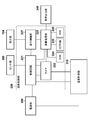
- FIG. 2 is an internal block diagram showing a functional configuration of the electronic thermometer 100 of the present embodiment.
- the electronic thermometer 100 has, as its operation mode, power consumption in a period when it is determined that the electronic thermometer 100 is left in addition to a normal body temperature measurement mode for measuring the body temperature of the subject. It has a low current consumption mode to reduce.
- This low current consumption mode is a mode in which operation is performed with lower power than that in the body temperature measurement mode.
- the electronic thermometer 100 calculates a body temperature of the subject by performing various processes based on the temperature measurement unit 210 that outputs an ON signal for a time corresponding to the temperature, and the ON signal output from the temperature measurement unit 210. And an arithmetic control unit 220 that controls the operation of the entire electronic thermometer 100. Further, the electronic thermometer 100 includes a display unit 104 that displays the calculated body temperature of the subject, an audio output unit 240 that outputs audio data, a power supply unit 250, and a sensor unit 260.
- the display part 104 is comprised by the liquid crystal display part for displaying measurement information, such as body temperature, for example.
- the display unit 104 can display status information of the electronic thermometer 100 (for example, a low current consumption mode, a body temperature measurement mode, etc.).
- the temperature measurement unit 210 includes a thermistor (measurement resistance element) and a reference resistance element, which are arranged in the end cap 103 and connected in parallel to each other, and a single input integration type A / D conversion circuit. Then, the temperature measurement unit 210 outputs an ON signal corresponding to the temperature (a digital signal that changes the ON time corresponding to the temperature).
- the integration method is adopted as the temperature measurement method of the temperature measurement unit 210.
- the present invention is not limited to this, and other methods such as a CR oscillation method using a CR oscillation circuit are used. It may be used.
- the arithmetic control unit 220 includes a timer 222 that measures the ON time of the digital signal output from the temperature measurement unit 210.
- the timer 222 can also measure the time since the power supply unit 250 is turned on.
- the arithmetic control unit 220 can control ON / OFF and reset of the timer 222 according to a predetermined condition. Therefore, the arithmetic control unit 220 can switch between the body temperature measurement mode and the low current consumption mode based on the measurement time of the timer 222 as a predetermined condition.
- the arithmetic control unit 220 includes a ROM 224, an EEPROM 225, and a RAM 226.
- the ROM 224 stores a program for calculating temperature data based on the time measured by the timer 222 and predicting and calculating the body temperature of the subject based on the time change of the calculated temperature data.
- the RAM 226 stores the calculated temperature data in time series.
- the EEPROM 225 stores predetermined audio data, calibration values, sample numbers, error information, the number of measurements, and the like.
- the arithmetic control unit 220 performs arithmetic operations according to programs stored in the ROM 224 and outputs audio data, and a display for controlling the display unit 104 that displays arithmetic results in the arithmetic processing unit 223.
- a control unit 227 is provided.
- the calculation control unit 220 includes a control circuit 221 that controls the timer 222, the display control unit 227, the calculation processing unit 223, the temperature measurement unit 210, and the sensor unit 260.
- the sensor unit 260 is a sensor for detecting the state of the electronic thermometer 100.
- This sensor includes a temperature sensor that detects the environmental temperature of the electronic thermometer 100, an acceleration sensor that detects a physical external force (tilt and vibration) acting on the electronic thermometer 100, a tilt / vibration switch, and an object to the electronic thermometer 100.
- thermometer 100 it is also possible to detect the environmental temperature of the electronic thermometer 100 by the temperature measurement unit 210 instead of mounting a temperature sensor on the sensor unit 260.
- the electronic thermometer 100 is provided with a magnet reed switch (not shown). For this reason, when the electronic thermometer 100 is taken out of the storage case 120, the magnet reed switch is turned on, and power is continuously supplied from the power supply unit 250 to various components such as the arithmetic control unit 220, the temperature measurement unit 210, and the display unit 104. It will be. And if the electronic thermometer 100 is accommodated in the storage case 120 containing a permanent magnet, supply of a power supply will be interrupted
- Body temperature measurement processing with electronic thermometer> First, the body temperature measurement process in the electronic thermometer executed in the body temperature measurement mode will be described.
- the temperature measurement process of the electronic thermometer 100 of the equilibrium temperature prediction type will be described, the present invention is not limited to this, and can be applied to an actual measurement type electronic thermometer and a prediction / measurement type electronic thermometer. .
- the electronic thermometer 100 When the electronic thermometer 100 is attached to the measurement site of the subject, the electronic thermometer 100 starts temperature measurement at a predetermined cycle (sampling rate), and the subject is based on the time change of the acquired temperature data. The body temperature is predicted.
- a predetermined cycle sampling rate
- FIG. 3 is a flowchart showing body temperature measurement processing in the electronic thermometer 100.
- the electronic thermometer 100 When the power supply unit 250 of the electronic thermometer 100 is turned on, the electronic thermometer 100 is initialized in step S301, and temperature measurement by the thermistor is started. For example, the arithmetic processing unit 223 calculates temperature data as a sampling rate for measuring body temperature at a predetermined interval, for example, every 0.5 seconds.
- step S302 it is determined whether or not a body temperature measurement start condition is satisfied. Specifically, whether or not the degree of increase from the value of the temperature data calculated by the previous temperature measurement (that is, the value of the temperature data 0.5 seconds before) has become a predetermined value (for example, 1 ° C.) or more. Determine whether.
- the degree of increase is equal to or greater than a predetermined value
- step S302 If it is determined in step S302 that the body temperature measurement start condition is satisfied (YES in step S302), the process proceeds to step S303, and temperature data acquisition is started. Specifically, the output temperature data and the timing at which the temperature data is measured are stored in the RAM 226 as time series data. On the other hand, if it is determined that the body temperature measurement start condition is not satisfied (NO in step S302), the process waits until it is determined that the body temperature measurement start condition is satisfied. Alternatively, when a predetermined time or more has elapsed, a low-consumption current mode described later may be entered as a measurement error.
- step S304 the predicted body temperature is calculated by a predetermined prediction formula using the temperature data stored in the RAM 226 in step S303.
- step S305 If it is determined in step S305 that the prediction establishment condition is satisfied (YES in step S305), the process proceeds to step S306, and the temperature measurement is terminated.
- step S307 a sound indicating that the calculation of the predicted body temperature has been completed is output, and the calculated predicted body temperature is displayed on the display unit 104 as the body temperature of the measured value.
- step S305 when it is determined in step S305 that the prediction establishment condition is not satisfied (NO in step S305), the process proceeds to step S309.
- a predetermined time for example, 45 seconds
- the magnet reed switch of the electronic thermometer 100 is turned off and the power supply from the power supply unit 250 is turned on. It is turned off.
- FIG. 4 is a diagram illustrating a detailed configuration of the temperature measurement unit 210.
- the thermistor 401 and the reference resistance element 402 are each connected to a capacitor 403.
- the capacitor 403 is charged to the voltage V from the voltage switching unit 410 via the thermistor 401 or the reference resistance element 402, but may be charged via a charging resistance element (not shown).
- the electric charge charged in the capacitor 403 is caused by dropping the voltage switching unit 410 connected to the thermistor 401 to the GND level, or dropping the voltage switching unit 410 connected to the reference resistance element 402 to the GND level. , And are discharged through the thermistor 401 and the reference resistance element 402, respectively. In discharging, the output of the voltage switching unit 410 that is not used for discharging is switched to high impedance.
- the reference resistance element 402 is a resistance element having a constant resistance value regardless of variations in ambient temperature. For this reason, when the voltage V is constant, the discharge time when discharged through the reference resistance element 402 is constant.
- the thermistor 401 is a resistance element whose resistance value fluctuates according to fluctuations in ambient temperature. For this reason, the discharge time when discharged via the thermistor 401 varies according to the ambient temperature.
- the discharge time is always constant when the voltage V is discharged through the reference resistance element 402, and when the voltage V is discharged through the thermistor 401, the discharge time is It depends on the temperature.
- the amount of charge accumulated in the capacitor 403 is detected via the A / D conversion unit 420.
- the comparator 421 that constitutes the A / D conversion unit 420 is used while the capacitor 403 has a voltage equal to or higher than a voltage (here, 0.25 V) of a predetermined ratio of the voltage V applied via the voltage switching unit 410. , A predetermined signal is output. As a result, the A / D converter 420 outputs an ON signal as a digital signal.
- the capacitor 403 and the A / D conversion unit 420 form a single input integration type A / D conversion circuit.
- the voltage across the capacitor 403 gradually decreases.
- the digital signal output from the A / D converter 420 becomes an OFF signal.
- the timer 222 measures the ON time (discharge time) of the digital signal output from the A / D converter 420.
- the discharge time is constant when discharged through the reference resistance element 402.
- the resistance value fluctuates according to the ambient temperature, so the discharge time also fluctuates.
- the electronic thermometer 100 measures the discharge time when the charge accumulated in the capacitor 403 is discharged through the thermistor 401 in a state where the ambient temperature is known (reference temperature). In addition, the electronic thermometer 100 measures the discharge time when the charge accumulated in the capacitor 403 is discharged through the reference resistance element 402.
- a standardized discharge time T at the measured temperature is calculated based on the following equation.
- a table representing the correspondence relationship between the discharge time and the temperature is recorded, and the normalized discharge time T is converted into temperature by comparing with the table.
- T T37 ⁇ (Tth / Tref) ⁇ (Tref37 / Tth37)
- the reference temperature is 37 ° C.
- Tref37 indicates a discharge time measured when discharging is performed through the reference resistance element 402 at the reference temperature.
- Tth37 indicates a discharge time measured when discharging is performed via the thermistor 401 at the reference temperature.
- Tref indicates a discharge time measured when discharging is performed through the reference resistance element 402 in the temperature measurement process.
- Tth indicates a discharge time measured when discharging is performed through the thermistor 401 in the temperature measurement process.
- T37 indicates a discharge time obtained when a resistance value serving as a reference for normalization is used at the reference temperature.
- FIG. 5 is a flowchart showing details of the temperature measurement process.
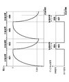
- FIG. 6 is a diagram showing the time change of the voltage across the capacitor 403 and the time change of the digital signal output from the A / D converter 420. A general temperature measurement process will be described with reference to FIGS. 5 and 6.
- step S501 the capacitor 403 is charged.
- Reference numeral 601 in FIG. 6 indicates a period (charge period) in which charges are gradually accumulated in the capacitor 403.
- step S502 discharge period 602
- the timer 222 measures the time of the ON signal.
- the time (discharge time 604) Tref from when the discharge is started until the voltage of the capacitor 403 becomes equal to or lower than a predetermined voltage (here, 0.25 V) is measured (see 602 in FIG. 6).
- Reference numeral 605 in FIG. 6 indicates a period (charge period) in which charges are gradually accumulated in the capacitor 403.
- the capacitor 403 is discharged in step S504 (discharge period 606).
- the timer 222 measures the time of the ON signal.
- Tth the time (discharge time 608) Tth from the start of discharge until the voltage of the capacitor 403 becomes equal to or lower than a predetermined voltage (here, 0.25 V) is measured. Tth varies depending on the ambient temperature of the thermistor 401.
- the fluctuation ratio is obtained and the standardized discharge time is calculated.
- step S506 the normalized discharge time T is converted into a temperature measurement result.
- the body temperature measurement mode is shifted to the low current consumption mode. Transition conditions for shifting to the low current consumption mode are as follows: 1. When the electronic thermometer 100 is left before the start or establishment of the temperature measurement. 2. When the temperature is soaked in the chemical solution or the electronic thermometer 100 is washed. It is assumed that the temperature has been measured at the rounds, but a certain period of time has passed (or left) before the health care workers (nurses, etc.) come to collect. Of course, it is possible to assume various factors other than the above and use them as the transition conditions. In other words, when the electronic thermometer 100 is not in a state where temperature measurement should not be performed in the body temperature measurement mode, the electronic thermometer 100 shifts to the low current consumption mode.
- the “temperature change:” in the return condition 1 means a case where the temperature of the surrounding environment of the electronic thermometer 100 is increased or the fluctuation range of the temperature in a constant temperature state is collapsed by a certain amount.
- the temperature measurement unit 210 it can be realized by a dedicated temperature sensor separately mounted on the sensor unit 260.
- the “interrupt for triggering the return” in the return condition 2 is, for example, calculation control when an acceleration sensor, a tilt switch, or a vibration switch mounted on the sensor unit 260 detects the tilt or vibration of the electronic thermometer 100.
- the transition to the body temperature measurement mode is made based on the presence or absence of an output from a sensor that can detect the situation to transition to the body temperature measurement mode.
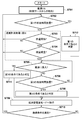
- FIG. 7 is a flowchart showing power control processing of the electronic thermometer.
- step S701 a magnet reed switch (not shown) of the electronic thermometer 100 is turned on, so that the power supply unit 250 of the electronic thermometer 100 is turned on. At this time, the electronic thermometer 100 shifts to the body temperature measurement mode.
- the power consumption at this time is, for example, about 60 ⁇ W.
- step S702 it is determined whether or not the electronic thermometer 100 has been left for a first predetermined time (for example, 10 minutes).
- a first predetermined time for example, 10 minutes.
- the process proceeds to step S712, and it is determined that the first condition is satisfied.
- the first condition is a case where the temperature measurement unit 210 is left after the start of temperature measurement.
- the determination of whether or not the temperature measurement is performed may be performed by, for example, temperature change of the temperature measurement unit 210 (steepness of a temperature gradient or Judgment is made by monitoring (temperature rise / fall). Then, it progresses to step S709 and transfers to a low consumption current mode.
- FIG. 8 is a diagram showing a state of temperature change with a series of usage modes (elapsed time) of the electronic thermometer.
- the electronic thermometer 100 after measuring the body temperature of the subject, the electronic thermometer 100 is wiped with alcohol absorbent cotton, then the body temperature of another subject is measured, washed with water, and the body temperature of another subject is further measured. It shows the temperature change when the electronic thermometer 100 is left after the measurement, after being put into the drug solution, and after measuring the body temperature of another subject.
- the temperature gradient rises according to the body temperature to be measured, and when reaching the body temperature of the subject, the temperature enters a constant temperature state. To establish. Thereafter, when the electronic thermometer 100 is collected from the subject and wiped with alcohol absorbent cotton, the temperature gradient suddenly drops due to a rapid temperature drop due to heat of vaporization (A region in the figure).
- the temperature is measured through a similar temperature change, and the electronic thermometer 100 is recovered from the subject and washed with water. Is deprived, and the temperature gradient drops relatively rapidly (B region in the figure).
- the temperature of the electronic thermometer 100 becomes constant (C region in the figure).
- the temperature is measured through the same temperature change, and the electronic thermometer 100 is collected from the subject and left to stand.
- the temperature gradually decreases with the temperature gradient (D region in the figure).
- a temperature change value indicating a temperature change within a certain time (for example, a steepness or inclination of a temperature gradient, a temperature difference), a threshold corresponding to each situation (A region to D region), and temperature measurement
- the determination is made using the temperature change value within a predetermined time obtained by the measurement of the unit 210. That is, when the temperature change value does not exceed the threshold value, it is determined that the electronic thermometer 100 is not in a state where temperature measurement should be performed in the body temperature measurement mode, and the mode is shifted to the low current consumption mode. On the other hand, when the temperature change value exceeds the threshold value, the electronic thermometer 100 determines that the body temperature measurement is to be performed in the body temperature measurement mode, and shifts to the body temperature measurement mode.
- step S703 it is determined whether or not temperature measurement is started. If it is determined that the temperature measurement is not started (NO in step S703), the process returns to step S702. On the other hand, when it is determined that the temperature detection is started (YES in step S703), the process proceeds to step S704, and it is determined whether or not the temperature detection is established. If it is determined that the temperature detection is not established (NO in step S704), the process returns to step S702. On the other hand, if it is determined that the temperature detection is established (YES in step S704), the process proceeds to step S705.
- step S703 and step S704 corresponds to the body temperature measurement process (body temperature measurement mode) in FIG.
- step S706 it is determined whether or not the electronic thermometer 100 has been charged (immersed) in the chemical solution. If it is determined that it is not put in the chemical (NO in step S705), it is determined in step S706 whether or not the electronic thermometer 100 has been left for a second predetermined time (for example, 3 minutes). If it is determined that the electronic thermometer 100 has not been left for the second predetermined time (NO in step S706), the process returns to step S705. On the other hand, when it is determined that the electronic thermometer 100 has been left for the second predetermined time (YES in step S706), the process proceeds to step S708, and it is determined that the second condition is satisfied.
- a second predetermined time for example, 3 minutes
- the second condition is when the electronic thermometer 100 is left after the temperature measurement is established, that is, when the temperature measurement unit 210 detects the state of the D region in FIG. Then, it progresses to step S709 and transfers to a low consumption current mode.
- step S705 if it is determined that the chemical solution has been introduced (YES in step S705), the process proceeds to step S711, where it is determined that the third condition is satisfied.
- the third condition is when the electronic thermometer 100 is immersed in the chemical solution, that is, when the temperature measurement unit 210 detects the state of the region C in FIG. Then, it progresses to step S709 and transfers to a low consumption current mode.
- step S704 the determination that it has been introduced into the chemical solution is performed after the temperature detection is established. However, even before the temperature measurement is established, the determination is made that the predetermined condition is satisfied. It is also possible to shift to the low current consumption mode.
- the transition to the low current consumption mode is performed using the temperature change detected by the temperature measurement unit 210, but the physical external force (inclination) acting on the electronic thermometer 100 detected by the sensor unit 260. It is also possible to shift to the low current consumption mode by determining whether or not to leave.
- This low current consumption mode is a mode for reducing the power consumption of the power supply unit 250, which is lower than the power consumption in the body temperature measurement mode, as described above. At this time, for example, power consumption is about 10 ⁇ W to 30 ⁇ W. Although a specific method for realizing low power consumption will be described later, power consumption varies depending on the method. Note that more power can be saved by performing a plurality of methods simultaneously.
- step S710 After shifting to the low current consumption mode, in step S710, it is determined whether or not the current state of the electronic thermometer 100 satisfies the return condition as described above. If it is determined that the return condition is not satisfied (NO in step S710), the process returns to step S709. On the other hand, when it is determined that the return condition is satisfied (YES in step S710), the low current consumption mode is returned to the body temperature measurement mode, and the process returns to step S702.
- Temperature measurement is stopped, and the display on the display unit 104 is fixed at the temperature at the time of measurement. Fixing this display means displaying / blinking / inverting an indicator (specific image, mark, text string) indicating that the measurement is stopped, or changing the background color / brightness or blacking out. Etc.
- the temperature measurement does not stop, but the display content on the display unit 104 blinks / extinguishes (reduction of current consumption necessary for display).
- the operating frequency of the electronic thermometer 100 is slowed (the slower the operating frequency, the smaller the current consumption).
- the current consumption during charging can be reduced by reducing the capacitance of the capacitor 403 or by switching the capacitor 403 to be selected according to temperature by having a plurality of capacitors 403. .
- the threshold value of the comparator 421 for example, from 0.25 Vcc to 0.5 Vcc
- the discharge time is shortened, and as a result, current consumption can be reduced.
- the electronic thermometer 100 even if the electronic thermometer 100 is left after the temperature measurement, it is desirable to store the temperature measurement result as the previous value in the RAM 226 so that the latest temperature measurement result can be confirmed immediately. By doing in this way, even in the low current consumption mode, the latest temperature measurement result (previous value) stored in the RAM 226 can be fixedly displayed on the display unit 104.
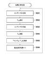
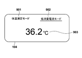
- FIG. 9 shows a display example of the display unit 104 in the low current consumption mode in such a case.
- the display unit 104 displays an index 901 indicating the body temperature measurement mode, an index 902 indicating the low current consumption mode, and a temperature value 903 to be displayed in each mode.
- an underline image is displayed under the index 901 or the index 902 to indicate which mode is the current mode.
- FIG. 9 shows a case where the current state is the low current consumption mode.
- the temperature value 903 that is the latest temperature measurement result (previous value) stored in the RAM 226 is displayed.
- the measured temperature may be displayed.
- the electronic thermometer 100 is attached to the subject's armpit, and the subject himself / herself displays the display unit 104. Since it is not easy to visually recognize the temperature, it is not always necessary to display the temperature during the temperature measurement. To the last, in the body temperature measurement mode, it is sufficient that the finally determined temperature value is displayed when the temperature measurement is established.
- the state of the electronic thermometer (stand, immersion, etc.) is determined by monitoring the temperature change within a certain time, and the body temperature is measured according to the determination state. Transition from mode to low current consumption mode. Thereafter, when the state of the electronic thermometer is in a state where the temperature should be measured, the state quickly shifts to the body temperature measurement mode.
- mode switching can be performed adaptively, the power saving of an electronic thermometer, in other words, improvement of a battery life can be aimed at.
- ⁇ Other embodiments> the configuration for switching the mode between the body temperature measurement mode and the low current consumption mode has been described, but the present invention is not limited to this. Further, in addition to these modes, a conventional auto power-off may be made to function. For example, when the mode is left for a long time (for example, 3 hours or more) after shifting to the low current consumption mode, the auto power off function may be functioned to further save power.
- the display unit 104 is configured to display an index indicating whether the body temperature measurement mode or the low current consumption mode and the temperature to be displayed in each mode are displayed. It is not limited to.
- the voice output unit 240 may provide voice guidance of which mode is the current mode and the temperature to be output in each mode. However, in this case, a configuration for outputting sound is required. For example, by providing an acceleration sensor or a contact sensor in the sensor unit 260 to give vibration or contact to an object to the electronic thermometer 100, mode information indicating a mode at that time and a temperature to be output corresponding to the mode Information may be output by voice.
Landscapes
- Physics & Mathematics (AREA)
- General Physics & Mathematics (AREA)
- Measuring Temperature Or Quantity Of Heat (AREA)
Applications Claiming Priority (2)
| Application Number | Priority Date | Filing Date | Title |
|---|---|---|---|
| JP2012-074453 | 2012-03-28 | ||
| JP2012074453A JP2015111049A (ja) | 2012-03-28 | 2012-03-28 | 電子体温計及びその制御方法 |
Publications (1)
| Publication Number | Publication Date |
|---|---|
| WO2013145542A1 true WO2013145542A1 (fr) | 2013-10-03 |
Family
ID=49258867
Family Applications (1)
| Application Number | Title | Priority Date | Filing Date |
|---|---|---|---|
| PCT/JP2013/001057 Ceased WO2013145542A1 (fr) | 2012-03-28 | 2013-02-25 | Thermomètre clinique électronique et son procédé de commande |
Country Status (2)
| Country | Link |
|---|---|
| JP (1) | JP2015111049A (fr) |
| WO (1) | WO2013145542A1 (fr) |
Cited By (4)
| Publication number | Priority date | Publication date | Assignee | Title |
|---|---|---|---|---|
| CN112639419A (zh) * | 2018-09-21 | 2021-04-09 | 欧姆龙株式会社 | 测震传感器以及传感器控制方法 |
| CN114076646A (zh) * | 2020-08-14 | 2022-02-22 | 泰尔茂株式会社 | 电子体温计以及信息处理方法 |
| CN114076645A (zh) * | 2020-08-14 | 2022-02-22 | 泰尔茂株式会社 | 电子体温计以及信息处理方法 |
| EP4459250A1 (fr) * | 2023-05-04 | 2024-11-06 | Vorwerk & Co. Interholding GmbH | Système thermométrique et conteneur pour un magasin de batterie thermométrique et utilisation |
Families Citing this family (2)
| Publication number | Priority date | Publication date | Assignee | Title |
|---|---|---|---|---|
| KR101723854B1 (ko) * | 2015-08-24 | 2017-04-06 | 주식회사 에스씨솔루션 | 임계 영역값을 기반으로 하여 자동으로 파워 온오프가 되는 디지털 센싱 장치 |
| JP6538732B2 (ja) * | 2017-01-17 | 2019-07-03 | 株式会社 ゼンショーホールディングス | 測定装置、測定システム、測定方法およびプログラム |
Citations (6)
| Publication number | Priority date | Publication date | Assignee | Title |
|---|---|---|---|---|
| JPS6050428A (ja) * | 1983-08-30 | 1985-03-20 | Toshiba Corp | 電子体温計 |
| JPS61213736A (ja) * | 1985-03-20 | 1986-09-22 | Omron Tateisi Electronics Co | 電子体温計 |
| JPS62257033A (ja) * | 1986-05-01 | 1987-11-09 | Omron Tateisi Electronics Co | 電子体温計 |
| JPS6364732B2 (fr) * | 1981-12-28 | 1988-12-13 | ||
| JPH0365484B2 (fr) * | 1982-08-11 | 1991-10-14 | ||
| WO2010109827A1 (fr) * | 2009-03-27 | 2010-09-30 | テルモ株式会社 | Thermomètre corporel électronique et procédé de commande de fonctionnement |
-
2012
- 2012-03-28 JP JP2012074453A patent/JP2015111049A/ja active Pending
-
2013
- 2013-02-25 WO PCT/JP2013/001057 patent/WO2013145542A1/fr not_active Ceased
Patent Citations (6)
| Publication number | Priority date | Publication date | Assignee | Title |
|---|---|---|---|---|
| JPS6364732B2 (fr) * | 1981-12-28 | 1988-12-13 | ||
| JPH0365484B2 (fr) * | 1982-08-11 | 1991-10-14 | ||
| JPS6050428A (ja) * | 1983-08-30 | 1985-03-20 | Toshiba Corp | 電子体温計 |
| JPS61213736A (ja) * | 1985-03-20 | 1986-09-22 | Omron Tateisi Electronics Co | 電子体温計 |
| JPS62257033A (ja) * | 1986-05-01 | 1987-11-09 | Omron Tateisi Electronics Co | 電子体温計 |
| WO2010109827A1 (fr) * | 2009-03-27 | 2010-09-30 | テルモ株式会社 | Thermomètre corporel électronique et procédé de commande de fonctionnement |
Cited By (7)
| Publication number | Priority date | Publication date | Assignee | Title |
|---|---|---|---|---|
| CN112639419A (zh) * | 2018-09-21 | 2021-04-09 | 欧姆龙株式会社 | 测震传感器以及传感器控制方法 |
| US12061302B2 (en) | 2018-09-21 | 2024-08-13 | Omron Corporation | Seismic sensor and sensor control method |
| CN114076646A (zh) * | 2020-08-14 | 2022-02-22 | 泰尔茂株式会社 | 电子体温计以及信息处理方法 |
| CN114076645A (zh) * | 2020-08-14 | 2022-02-22 | 泰尔茂株式会社 | 电子体温计以及信息处理方法 |
| CN114076645B (zh) * | 2020-08-14 | 2024-03-08 | 泰尔茂株式会社 | 电子体温计以及信息处理方法 |
| CN114076646B (zh) * | 2020-08-14 | 2024-03-12 | 泰尔茂株式会社 | 电子体温计以及信息处理方法 |
| EP4459250A1 (fr) * | 2023-05-04 | 2024-11-06 | Vorwerk & Co. Interholding GmbH | Système thermométrique et conteneur pour un magasin de batterie thermométrique et utilisation |
Also Published As
| Publication number | Publication date |
|---|---|
| JP2015111049A (ja) | 2015-06-18 |
Similar Documents
| Publication | Publication Date | Title |
|---|---|---|
| WO2013145542A1 (fr) | Thermomètre clinique électronique et son procédé de commande | |
| JP5215060B2 (ja) | 電子体温計及び作動制御方法 | |
| TW200413705A (en) | Portable electronic device including capacitive water detection means and method of implementation | |
| RU2010128612A (ru) | Управление быстрым зарядом и питанием выполненного с батарейным питанием измерителя аналитов в текучей среде | |
| JP5596323B2 (ja) | 電子体温計及び電子体温計の制御方法 | |
| US7778791B2 (en) | Electronic clinical thermometer, method of controlling the same, and control program | |
| WO2007007607A1 (fr) | Thermomètre clinique électronique, et procédé de commande et programme de commande pour thermomètre clinique électronique | |
| JP5513283B2 (ja) | 電子体温計用の装着ユニット及びその制御方法 | |
| JP5432066B2 (ja) | 電子体温計及びその制御方法 | |
| EP1906162B1 (fr) | Thermometre clinique electronique, procede de commande et programme de commande pour thermometre clinique electronique | |
| JP2012125349A (ja) | 女性体温計及び制御方法 | |
| CN102317747B (zh) | 电子体温计及动作控制方法 | |
| JP5300613B2 (ja) | 電子体温計 | |
| JP5706151B2 (ja) | 電子体温計及び電子体温計の制御方法 | |
| JP5457235B2 (ja) | 電子体温計およびその表示制御方法 | |
| JP5960908B2 (ja) | 電子体温計 | |
| JP4754893B2 (ja) | 電子体温計 | |
| CN114076646B (zh) | 电子体温计以及信息处理方法 | |
| JP4920922B2 (ja) | 電子体温計 | |
| WO2013140715A1 (fr) | Thermomètre clinique électronique, procédé de traitement de celui -ci, et son procédé de commande | |
| TW201413438A (zh) | 管理電子設備之改良方法 | |
| JP2013134224A (ja) | 電子体温計 | |
| JP2013170935A (ja) | カバー付き電子体温計 | |
| JP5330166B2 (ja) | 電子体温計 | |
| JP3159026U (ja) | 電子体温計 |
Legal Events
| Date | Code | Title | Description |
|---|---|---|---|
| 121 | Ep: the epo has been informed by wipo that ep was designated in this application |
Ref document number: 13768925 Country of ref document: EP Kind code of ref document: A1 |
|
| NENP | Non-entry into the national phase |
Ref country code: DE |
|
| 122 | Ep: pct application non-entry in european phase |
Ref document number: 13768925 Country of ref document: EP Kind code of ref document: A1 |
|
| NENP | Non-entry into the national phase |
Ref country code: JP |