WO2013145575A1 - Dispositif de transmission de puissance et engins de chantier hybrides équipés de celui-ci - Google Patents
Dispositif de transmission de puissance et engins de chantier hybrides équipés de celui-ci Download PDFInfo
- Publication number
- WO2013145575A1 WO2013145575A1 PCT/JP2013/001410 JP2013001410W WO2013145575A1 WO 2013145575 A1 WO2013145575 A1 WO 2013145575A1 JP 2013001410 W JP2013001410 W JP 2013001410W WO 2013145575 A1 WO2013145575 A1 WO 2013145575A1
- Authority
- WO
- WIPO (PCT)
- Prior art keywords
- power
- engine
- electric motor
- generator
- transmission device
- Prior art date
- Legal status (The legal status is an assumption and is not a legal conclusion. Google has not performed a legal analysis and makes no representation as to the accuracy of the status listed.)
- Ceased
Links
Images



Classifications
-
- E—FIXED CONSTRUCTIONS
- E02—HYDRAULIC ENGINEERING; FOUNDATIONS; SOIL SHIFTING
- E02F—DREDGING; SOIL-SHIFTING
- E02F9/00—Component parts of dredgers or soil-shifting machines, not restricted to one of the kinds covered by groups E02F3/00 - E02F7/00
- E02F9/20—Drives; Control devices
- E02F9/2058—Electric or electro-mechanical or mechanical control devices of vehicle sub-units
- E02F9/2062—Control of propulsion units
- E02F9/2075—Control of propulsion units of the hybrid type
-
- B—PERFORMING OPERATIONS; TRANSPORTING
- B60—VEHICLES IN GENERAL
- B60K—ARRANGEMENT OR MOUNTING OF PROPULSION UNITS OR OF TRANSMISSIONS IN VEHICLES; ARRANGEMENT OR MOUNTING OF PLURAL DIVERSE PRIME-MOVERS IN VEHICLES; AUXILIARY DRIVES FOR VEHICLES; INSTRUMENTATION OR DASHBOARDS FOR VEHICLES; ARRANGEMENTS IN CONNECTION WITH COOLING, AIR INTAKE, GAS EXHAUST OR FUEL SUPPLY OF PROPULSION UNITS IN VEHICLES
- B60K6/00—Arrangement or mounting of plural diverse prime-movers for mutual or common propulsion, e.g. hybrid propulsion systems comprising electric motors and internal combustion engines
- B60K6/20—Arrangement or mounting of plural diverse prime-movers for mutual or common propulsion, e.g. hybrid propulsion systems comprising electric motors and internal combustion engines the prime-movers consisting of electric motors and internal combustion engines, e.g. HEVs
- B60K6/22—Arrangement or mounting of plural diverse prime-movers for mutual or common propulsion, e.g. hybrid propulsion systems comprising electric motors and internal combustion engines the prime-movers consisting of electric motors and internal combustion engines, e.g. HEVs characterised by apparatus, components or means specially adapted for HEVs
-
- B—PERFORMING OPERATIONS; TRANSPORTING
- B60—VEHICLES IN GENERAL
- B60K—ARRANGEMENT OR MOUNTING OF PROPULSION UNITS OR OF TRANSMISSIONS IN VEHICLES; ARRANGEMENT OR MOUNTING OF PLURAL DIVERSE PRIME-MOVERS IN VEHICLES; AUXILIARY DRIVES FOR VEHICLES; INSTRUMENTATION OR DASHBOARDS FOR VEHICLES; ARRANGEMENTS IN CONNECTION WITH COOLING, AIR INTAKE, GAS EXHAUST OR FUEL SUPPLY OF PROPULSION UNITS IN VEHICLES
- B60K6/00—Arrangement or mounting of plural diverse prime-movers for mutual or common propulsion, e.g. hybrid propulsion systems comprising electric motors and internal combustion engines
- B60K6/20—Arrangement or mounting of plural diverse prime-movers for mutual or common propulsion, e.g. hybrid propulsion systems comprising electric motors and internal combustion engines the prime-movers consisting of electric motors and internal combustion engines, e.g. HEVs
- B60K6/22—Arrangement or mounting of plural diverse prime-movers for mutual or common propulsion, e.g. hybrid propulsion systems comprising electric motors and internal combustion engines the prime-movers consisting of electric motors and internal combustion engines, e.g. HEVs characterised by apparatus, components or means specially adapted for HEVs
- B60K6/30—Arrangement or mounting of plural diverse prime-movers for mutual or common propulsion, e.g. hybrid propulsion systems comprising electric motors and internal combustion engines the prime-movers consisting of electric motors and internal combustion engines, e.g. HEVs characterised by apparatus, components or means specially adapted for HEVs characterised by chargeable mechanical accumulators, e.g. flywheels
-
- B—PERFORMING OPERATIONS; TRANSPORTING
- B60—VEHICLES IN GENERAL
- B60K—ARRANGEMENT OR MOUNTING OF PROPULSION UNITS OR OF TRANSMISSIONS IN VEHICLES; ARRANGEMENT OR MOUNTING OF PLURAL DIVERSE PRIME-MOVERS IN VEHICLES; AUXILIARY DRIVES FOR VEHICLES; INSTRUMENTATION OR DASHBOARDS FOR VEHICLES; ARRANGEMENTS IN CONNECTION WITH COOLING, AIR INTAKE, GAS EXHAUST OR FUEL SUPPLY OF PROPULSION UNITS IN VEHICLES
- B60K6/00—Arrangement or mounting of plural diverse prime-movers for mutual or common propulsion, e.g. hybrid propulsion systems comprising electric motors and internal combustion engines
- B60K6/20—Arrangement or mounting of plural diverse prime-movers for mutual or common propulsion, e.g. hybrid propulsion systems comprising electric motors and internal combustion engines the prime-movers consisting of electric motors and internal combustion engines, e.g. HEVs
- B60K6/22—Arrangement or mounting of plural diverse prime-movers for mutual or common propulsion, e.g. hybrid propulsion systems comprising electric motors and internal combustion engines the prime-movers consisting of electric motors and internal combustion engines, e.g. HEVs characterised by apparatus, components or means specially adapted for HEVs
- B60K6/38—Arrangement or mounting of plural diverse prime-movers for mutual or common propulsion, e.g. hybrid propulsion systems comprising electric motors and internal combustion engines the prime-movers consisting of electric motors and internal combustion engines, e.g. HEVs characterised by apparatus, components or means specially adapted for HEVs characterised by the driveline clutches
- B60K6/387—Actuated clutches, i.e. clutches engaged or disengaged by electric, hydraulic or mechanical actuating means
-
- B—PERFORMING OPERATIONS; TRANSPORTING
- B60—VEHICLES IN GENERAL
- B60K—ARRANGEMENT OR MOUNTING OF PROPULSION UNITS OR OF TRANSMISSIONS IN VEHICLES; ARRANGEMENT OR MOUNTING OF PLURAL DIVERSE PRIME-MOVERS IN VEHICLES; AUXILIARY DRIVES FOR VEHICLES; INSTRUMENTATION OR DASHBOARDS FOR VEHICLES; ARRANGEMENTS IN CONNECTION WITH COOLING, AIR INTAKE, GAS EXHAUST OR FUEL SUPPLY OF PROPULSION UNITS IN VEHICLES
- B60K6/00—Arrangement or mounting of plural diverse prime-movers for mutual or common propulsion, e.g. hybrid propulsion systems comprising electric motors and internal combustion engines
- B60K6/20—Arrangement or mounting of plural diverse prime-movers for mutual or common propulsion, e.g. hybrid propulsion systems comprising electric motors and internal combustion engines the prime-movers consisting of electric motors and internal combustion engines, e.g. HEVs
- B60K6/42—Arrangement or mounting of plural diverse prime-movers for mutual or common propulsion, e.g. hybrid propulsion systems comprising electric motors and internal combustion engines the prime-movers consisting of electric motors and internal combustion engines, e.g. HEVs characterised by the architecture of the hybrid electric vehicle
- B60K6/44—Series-parallel type
- B60K6/445—Differential gearing distribution type
-
- B—PERFORMING OPERATIONS; TRANSPORTING
- B60—VEHICLES IN GENERAL
- B60K—ARRANGEMENT OR MOUNTING OF PROPULSION UNITS OR OF TRANSMISSIONS IN VEHICLES; ARRANGEMENT OR MOUNTING OF PLURAL DIVERSE PRIME-MOVERS IN VEHICLES; AUXILIARY DRIVES FOR VEHICLES; INSTRUMENTATION OR DASHBOARDS FOR VEHICLES; ARRANGEMENTS IN CONNECTION WITH COOLING, AIR INTAKE, GAS EXHAUST OR FUEL SUPPLY OF PROPULSION UNITS IN VEHICLES
- B60K6/00—Arrangement or mounting of plural diverse prime-movers for mutual or common propulsion, e.g. hybrid propulsion systems comprising electric motors and internal combustion engines
- B60K6/20—Arrangement or mounting of plural diverse prime-movers for mutual or common propulsion, e.g. hybrid propulsion systems comprising electric motors and internal combustion engines the prime-movers consisting of electric motors and internal combustion engines, e.g. HEVs
- B60K6/42—Arrangement or mounting of plural diverse prime-movers for mutual or common propulsion, e.g. hybrid propulsion systems comprising electric motors and internal combustion engines the prime-movers consisting of electric motors and internal combustion engines, e.g. HEVs characterised by the architecture of the hybrid electric vehicle
- B60K6/46—Series type
-
- B—PERFORMING OPERATIONS; TRANSPORTING
- B60—VEHICLES IN GENERAL
- B60K—ARRANGEMENT OR MOUNTING OF PROPULSION UNITS OR OF TRANSMISSIONS IN VEHICLES; ARRANGEMENT OR MOUNTING OF PLURAL DIVERSE PRIME-MOVERS IN VEHICLES; AUXILIARY DRIVES FOR VEHICLES; INSTRUMENTATION OR DASHBOARDS FOR VEHICLES; ARRANGEMENTS IN CONNECTION WITH COOLING, AIR INTAKE, GAS EXHAUST OR FUEL SUPPLY OF PROPULSION UNITS IN VEHICLES
- B60K6/00—Arrangement or mounting of plural diverse prime-movers for mutual or common propulsion, e.g. hybrid propulsion systems comprising electric motors and internal combustion engines
- B60K6/20—Arrangement or mounting of plural diverse prime-movers for mutual or common propulsion, e.g. hybrid propulsion systems comprising electric motors and internal combustion engines the prime-movers consisting of electric motors and internal combustion engines, e.g. HEVs
- B60K6/50—Architecture of the driveline characterised by arrangement or kind of transmission units
- B60K6/54—Transmission for changing ratio
-
- B—PERFORMING OPERATIONS; TRANSPORTING
- B60—VEHICLES IN GENERAL
- B60L—PROPULSION OF ELECTRICALLY-PROPELLED VEHICLES; SUPPLYING ELECTRIC POWER FOR AUXILIARY EQUIPMENT OF ELECTRICALLY-PROPELLED VEHICLES; ELECTRODYNAMIC BRAKE SYSTEMS FOR VEHICLES IN GENERAL; MAGNETIC SUSPENSION OR LEVITATION FOR VEHICLES; MONITORING OPERATING VARIABLES OF ELECTRICALLY-PROPELLED VEHICLES; ELECTRIC SAFETY DEVICES FOR ELECTRICALLY-PROPELLED VEHICLES
- B60L1/00—Supplying electric power to auxiliary equipment of vehicles
- B60L1/003—Supplying electric power to auxiliary equipment of vehicles to auxiliary motors, e.g. for pumps, compressors
-
- B—PERFORMING OPERATIONS; TRANSPORTING
- B60—VEHICLES IN GENERAL
- B60L—PROPULSION OF ELECTRICALLY-PROPELLED VEHICLES; SUPPLYING ELECTRIC POWER FOR AUXILIARY EQUIPMENT OF ELECTRICALLY-PROPELLED VEHICLES; ELECTRODYNAMIC BRAKE SYSTEMS FOR VEHICLES IN GENERAL; MAGNETIC SUSPENSION OR LEVITATION FOR VEHICLES; MONITORING OPERATING VARIABLES OF ELECTRICALLY-PROPELLED VEHICLES; ELECTRIC SAFETY DEVICES FOR ELECTRICALLY-PROPELLED VEHICLES
- B60L50/00—Electric propulsion with power supplied within the vehicle
- B60L50/10—Electric propulsion with power supplied within the vehicle using propulsion power supplied by engine-driven generators, e.g. generators driven by combustion engines
- B60L50/15—Electric propulsion with power supplied within the vehicle using propulsion power supplied by engine-driven generators, e.g. generators driven by combustion engines with additional electric power supply
-
- B—PERFORMING OPERATIONS; TRANSPORTING
- B60—VEHICLES IN GENERAL
- B60L—PROPULSION OF ELECTRICALLY-PROPELLED VEHICLES; SUPPLYING ELECTRIC POWER FOR AUXILIARY EQUIPMENT OF ELECTRICALLY-PROPELLED VEHICLES; ELECTRODYNAMIC BRAKE SYSTEMS FOR VEHICLES IN GENERAL; MAGNETIC SUSPENSION OR LEVITATION FOR VEHICLES; MONITORING OPERATING VARIABLES OF ELECTRICALLY-PROPELLED VEHICLES; ELECTRIC SAFETY DEVICES FOR ELECTRICALLY-PROPELLED VEHICLES
- B60L50/00—Electric propulsion with power supplied within the vehicle
- B60L50/10—Electric propulsion with power supplied within the vehicle using propulsion power supplied by engine-driven generators, e.g. generators driven by combustion engines
- B60L50/16—Electric propulsion with power supplied within the vehicle using propulsion power supplied by engine-driven generators, e.g. generators driven by combustion engines with provision for separate direct mechanical propulsion
-
- B—PERFORMING OPERATIONS; TRANSPORTING
- B60—VEHICLES IN GENERAL
- B60W—CONJOINT CONTROL OF VEHICLE SUB-UNITS OF DIFFERENT TYPE OR DIFFERENT FUNCTION; CONTROL SYSTEMS SPECIALLY ADAPTED FOR HYBRID VEHICLES; ROAD VEHICLE DRIVE CONTROL SYSTEMS FOR PURPOSES NOT RELATED TO THE CONTROL OF A PARTICULAR SUB-UNIT
- B60W10/00—Conjoint control of vehicle sub-units of different type or different function
- B60W10/04—Conjoint control of vehicle sub-units of different type or different function including control of propulsion units
- B60W10/06—Conjoint control of vehicle sub-units of different type or different function including control of propulsion units including control of combustion engines
-
- B—PERFORMING OPERATIONS; TRANSPORTING
- B60—VEHICLES IN GENERAL
- B60W—CONJOINT CONTROL OF VEHICLE SUB-UNITS OF DIFFERENT TYPE OR DIFFERENT FUNCTION; CONTROL SYSTEMS SPECIALLY ADAPTED FOR HYBRID VEHICLES; ROAD VEHICLE DRIVE CONTROL SYSTEMS FOR PURPOSES NOT RELATED TO THE CONTROL OF A PARTICULAR SUB-UNIT
- B60W10/00—Conjoint control of vehicle sub-units of different type or different function
- B60W10/10—Conjoint control of vehicle sub-units of different type or different function including control of change-speed gearings
- B60W10/101—Infinitely variable gearings
- B60W10/103—Infinitely variable gearings of fluid type
-
- B—PERFORMING OPERATIONS; TRANSPORTING
- B60—VEHICLES IN GENERAL
- B60W—CONJOINT CONTROL OF VEHICLE SUB-UNITS OF DIFFERENT TYPE OR DIFFERENT FUNCTION; CONTROL SYSTEMS SPECIALLY ADAPTED FOR HYBRID VEHICLES; ROAD VEHICLE DRIVE CONTROL SYSTEMS FOR PURPOSES NOT RELATED TO THE CONTROL OF A PARTICULAR SUB-UNIT
- B60W20/00—Control systems specially adapted for hybrid vehicles
-
- E—FIXED CONSTRUCTIONS
- E02—HYDRAULIC ENGINEERING; FOUNDATIONS; SOIL SHIFTING
- E02F—DREDGING; SOIL-SHIFTING
- E02F9/00—Component parts of dredgers or soil-shifting machines, not restricted to one of the kinds covered by groups E02F3/00 - E02F7/00
- E02F9/20—Drives; Control devices
- E02F9/202—Mechanical transmission, e.g. clutches, gears
-
- B—PERFORMING OPERATIONS; TRANSPORTING
- B60—VEHICLES IN GENERAL
- B60L—PROPULSION OF ELECTRICALLY-PROPELLED VEHICLES; SUPPLYING ELECTRIC POWER FOR AUXILIARY EQUIPMENT OF ELECTRICALLY-PROPELLED VEHICLES; ELECTRODYNAMIC BRAKE SYSTEMS FOR VEHICLES IN GENERAL; MAGNETIC SUSPENSION OR LEVITATION FOR VEHICLES; MONITORING OPERATING VARIABLES OF ELECTRICALLY-PROPELLED VEHICLES; ELECTRIC SAFETY DEVICES FOR ELECTRICALLY-PROPELLED VEHICLES
- B60L2200/00—Type of vehicles
- B60L2200/40—Working vehicles
-
- B—PERFORMING OPERATIONS; TRANSPORTING
- B60—VEHICLES IN GENERAL
- B60W—CONJOINT CONTROL OF VEHICLE SUB-UNITS OF DIFFERENT TYPE OR DIFFERENT FUNCTION; CONTROL SYSTEMS SPECIALLY ADAPTED FOR HYBRID VEHICLES; ROAD VEHICLE DRIVE CONTROL SYSTEMS FOR PURPOSES NOT RELATED TO THE CONTROL OF A PARTICULAR SUB-UNIT
- B60W2300/00—Indexing codes relating to the type of vehicle
- B60W2300/17—Construction vehicles, e.g. graders, excavators
-
- F—MECHANICAL ENGINEERING; LIGHTING; HEATING; WEAPONS; BLASTING
- F02—COMBUSTION ENGINES; HOT-GAS OR COMBUSTION-PRODUCT ENGINE PLANTS
- F02D—CONTROLLING COMBUSTION ENGINES
- F02D29/00—Controlling engines, such controlling being peculiar to the devices driven thereby, the devices being other than parts or accessories essential to engine operation, e.g. controlling of engines by signals external thereto
- F02D29/04—Controlling engines, such controlling being peculiar to the devices driven thereby, the devices being other than parts or accessories essential to engine operation, e.g. controlling of engines by signals external thereto peculiar to engines driving pumps
-
- F—MECHANICAL ENGINEERING; LIGHTING; HEATING; WEAPONS; BLASTING
- F02—COMBUSTION ENGINES; HOT-GAS OR COMBUSTION-PRODUCT ENGINE PLANTS
- F02D—CONTROLLING COMBUSTION ENGINES
- F02D29/00—Controlling engines, such controlling being peculiar to the devices driven thereby, the devices being other than parts or accessories essential to engine operation, e.g. controlling of engines by signals external thereto
- F02D29/06—Controlling engines, such controlling being peculiar to the devices driven thereby, the devices being other than parts or accessories essential to engine operation, e.g. controlling of engines by signals external thereto peculiar to engines driving electric generators
-
- Y—GENERAL TAGGING OF NEW TECHNOLOGICAL DEVELOPMENTS; GENERAL TAGGING OF CROSS-SECTIONAL TECHNOLOGIES SPANNING OVER SEVERAL SECTIONS OF THE IPC; TECHNICAL SUBJECTS COVERED BY FORMER USPC CROSS-REFERENCE ART COLLECTIONS [XRACs] AND DIGESTS
- Y02—TECHNOLOGIES OR APPLICATIONS FOR MITIGATION OR ADAPTATION AGAINST CLIMATE CHANGE
- Y02T—CLIMATE CHANGE MITIGATION TECHNOLOGIES RELATED TO TRANSPORTATION
- Y02T10/00—Road transport of goods or passengers
- Y02T10/60—Other road transportation technologies with climate change mitigation effect
- Y02T10/62—Hybrid vehicles
-
- Y—GENERAL TAGGING OF NEW TECHNOLOGICAL DEVELOPMENTS; GENERAL TAGGING OF CROSS-SECTIONAL TECHNOLOGIES SPANNING OVER SEVERAL SECTIONS OF THE IPC; TECHNICAL SUBJECTS COVERED BY FORMER USPC CROSS-REFERENCE ART COLLECTIONS [XRACs] AND DIGESTS
- Y02—TECHNOLOGIES OR APPLICATIONS FOR MITIGATION OR ADAPTATION AGAINST CLIMATE CHANGE
- Y02T—CLIMATE CHANGE MITIGATION TECHNOLOGIES RELATED TO TRANSPORTATION
- Y02T10/00—Road transport of goods or passengers
- Y02T10/60—Other road transportation technologies with climate change mitigation effect
- Y02T10/70—Energy storage systems for electromobility, e.g. batteries
-
- Y—GENERAL TAGGING OF NEW TECHNOLOGICAL DEVELOPMENTS; GENERAL TAGGING OF CROSS-SECTIONAL TECHNOLOGIES SPANNING OVER SEVERAL SECTIONS OF THE IPC; TECHNICAL SUBJECTS COVERED BY FORMER USPC CROSS-REFERENCE ART COLLECTIONS [XRACs] AND DIGESTS
- Y02—TECHNOLOGIES OR APPLICATIONS FOR MITIGATION OR ADAPTATION AGAINST CLIMATE CHANGE
- Y02T—CLIMATE CHANGE MITIGATION TECHNOLOGIES RELATED TO TRANSPORTATION
- Y02T10/00—Road transport of goods or passengers
- Y02T10/60—Other road transportation technologies with climate change mitigation effect
- Y02T10/7072—Electromobility specific charging systems or methods for batteries, ultracapacitors, supercapacitors or double-layer capacitors
Definitions
- the present invention relates to a hybrid construction machine having an engine, a generator that generates electric power using the engine, and a hydraulic pump that can be driven by the electric power generated by the generator.
- the hybrid construction machine one that adopts a series hybrid system and one that adopts a parallel hybrid system are known.
- Patent Document 1 A construction machine that employs a series hybrid system is described in Patent Document 1, for example.
- the construction machine described in Patent Document 1 includes an engine, a generator driven by the engine, an electric motor supplied with electric power generated by the generator, and a hydraulic pump driven by the electric motor. ing.
- the engine and the hydraulic pump are not mechanically connected.
- an engine in a parallel hybrid system, an engine, a hydraulic pump driven by the engine, and an electric power that can be stored in a capacitor by operating as a generator by the power of the engine, and hydraulic pressure by operating as an electric motor by electric power from the capacitor.
- a generator motor capable of assisting an engine driving the pump.
- the generator motor since one generator motor is used as both a generator and a motor, the generator motor cannot be used efficiently. Specifically, while the output of the generator motor is different from the output at the time of assist, the rated output set for one generator motor is one, so the rated output at each time of power generation and assist Cannot be used effectively.
- An object of the present invention is to provide a power transmission device that can directly use power of an engine as power of a hydraulic pump, and that can efficiently generate power and assist, and a hybrid construction machine including the power transmission device. .
- the present invention is a power transmission device provided in a hybrid construction machine, and includes an engine, a generator capable of generating power by operating with the power of the engine, and power generated by the generator.
- a battery capable of storing stored electric power, an electric motor operable by the power of the engine and the electric power of the battery, a hydraulic pump connected to the electric motor to be driven by the operation of the electric motor, and the power of the engine
- a power transmission device including the engine, the generator, and a power divider connected to the electric motor so as to be distributed to the generator and the electric motor.
- the present invention also provides a hybrid construction machine comprising a hydraulic actuator and the power transmission device having a hydraulic pump that drives the hydraulic actuator.
- the power of the engine can be directly used as power of the hydraulic pump, and power generation and assist can be performed efficiently.
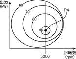
- FIG. 2 is a block diagram showing a schematic configuration of a power transmission device according to a modification of the embodiment. It is a graph which shows the drive efficiency of the generator shown in FIG. It is a flowchart which shows the process performed by the power controller shown in FIG.
- a hybrid excavator 1 that is an example of a hybrid construction machine according to the present invention includes a self-propelled lower traveling body 2, an upper revolving body 3 that is turnably provided on the lower traveling body 2, and the power transmission shown in FIG. Device 4.
- the lower traveling body 2 includes a pair of left and right crawlers 2a and travel motors (not shown) provided on the crawlers 2a.
- the upper swing body 3 includes an upper frame 5 mounted on the lower traveling body 2 so as to be pivotable, a swing motor (not shown) that swings the upper frame 5 with respect to the lower traveling body 2, and an upper frame 5. And a work attachment 6 that can be raised and lowered.
- the work attachment 6 includes a boom 7 having a base end portion attached to the upper frame 5 so as to be able to move up and down, and an arm 8 having a base end portion provided so as to be swingable with respect to the tip end portion of the boom 7; And a bucket 9 provided so as to be swingable with respect to the distal end portion of the arm 8.
- the work attachment also includes a boom cylinder 10 that moves the boom 7 up and down relative to the upper frame 5, an arm cylinder 11 that swings the arm 8 relative to the boom 7, and a bucket 9 that swings relative to the arm 8.
- the travel motor (not shown) of the lower traveling body 2, the swing motor (not shown) of the upper swing body 3, and the cylinders 10 to 12 constitute a hydraulic actuator in this embodiment.
- the power transmission device 4 includes an engine 14, a power generator 15 that can generate power by operating with the power of the engine 14, a battery 19 that can store electric power generated by the power generator 15, power of the engine 14, and the battery 19.
- the motor 16 that can be operated by the electric power of the motor, the hydraulic pump 18 that is connected to the motor 16 to be driven by the operation of the motor 16, the power divider 17 that distributes the power of the engine 14, and the drive of the generator 15 are controlled.
- a generator controller 20, a motor controller 21 that controls driving of the motor 16, and a power controller 22 that outputs a control command to the generator controller 20 and the motor controller 21 are provided.
- the generator 15 is connected to the engine 14 via the power divider 17 so that the power from the engine 14 can be received.
- the battery 19 can store the electric power generated by the generator 15 and can supply the electric power stored in the electric motor 16. Specifically, the battery 19 is electrically connected to the generator 15 and the electric motor 16.
- the electric motor 16 is connected to the engine 14 via the power divider 17 so that the power from the engine 14 can be received.
- the electric motor 16 can receive power from the battery 19 while receiving power from the engine 14, thereby supplying power from the motor 16 to the hydraulic pump 18 in addition to power from the engine 14 ( The engine 14 can be assisted).
- the hydraulic pump 18 discharges hydraulic oil for driving at least one of the hydraulic actuators (travel motor (not shown), swing motor (not shown), and cylinders 10 to 12).
- the power divider 17 distributes the power of the engine 14 to the generator 15 and the electric motor 16.
- the power divider 17 has a gear mechanism for distributing the power of the engine 14 to two systems.
- the power divider 17 according to the present embodiment has a gear mechanism in which the gear ratio between the rotational speed of the engine 14 and the rotational speeds of the generator 15 and the electric motor 16 is 1: 1. Therefore, the power of the engine 14 is distributed to the generator 15 and the electric motor 16 in a state where the rotational speed of the engine 14 is maintained.
- the generator controller 20 controls the amount of power generated by the generator 15. Specifically, the generator controller 20 controls the torque for the generator 15.
- the generator controller 20 can be configured by an inverter, for example.
- the electric motor controller 21 controls the driving of the electric motor 16. Specifically, the electric motor controller 21 controls the current from the battery 19 to the electric motor 16.
- the electric motor controller 21 can be constituted by an inverter, for example.
- the power controller 22 outputs a control command to the generator controller 20 and the motor controller 21 in accordance with the operating state of the engine 14. Specifically, the power controller 22 outputs a control command for generating power to the generator controller 20 when there is a margin in the power of the engine 14. On the other hand, the power controller 22 outputs a control command for assisting the electric motor controller 21 with the electric motor 16 when the power of the engine 14 is not sufficient.
- the generator 15 for power generation and the electric motor 16 for assisting the engine 14 are individually provided, and the electric generator 15 and the electric motor 16 are connected via the power divider 17. Connected to the engine 14. Thereby, the power of the engine 14 can be directly used as the power of the electric motor 16 (hydraulic pump 18) while generating power with the power of the engine 14. On the other hand, the hydraulic pump 18 can be driven by operating the electric motor 16 with the electric power of the battery 19, that is, the engine 14 can be assisted.
- the embodiment has the following effects. Specifically, since the power of the engine 14 can be directly used as the power of the hydraulic pump 18, the output required for the electric motor 16 can be kept small, and the electric motor 16 can be made small. Further, when there is a margin in the output of the engine 14 or when a failure occurs in the electrical system, the hydraulic pump 18 can be driven using the power of the engine 14.
- the generator 15 for power generation and the electric motor 16 for assistance are individually provided. Therefore, by selecting the generator 15 having a rated output corresponding to the output during power generation and selecting the motor 16 having the rated output corresponding to the output during assist, power generation and assist can be performed efficiently. .
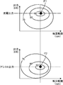
- the power generation output is larger than the assist output.
- the rated output P3 of the generator motor is effectively used. I can't. That is, the limit is to select a generator motor having a rated output between the power generation output and the assist output.
- the power of the engine 14 can be directly used as the power of the hydraulic pump 18, and power generation and assist can be performed efficiently.
- the power transmission device 4 includes a speed increasing mechanism (transmission mechanism) 23 provided in the power divider 17, a clutch 24 provided between the power divider 17 and the electric motor 16, and a switching operation of the clutch 24.
- a clutch switching member 25 an engine controller 27 that controls driving of the engine 14, and a charge amount detector 26 that detects the charge amount of the battery 19.
- the speed increasing mechanism 23 changes the rotational speed of the engine 14 so that the rotational speed of the generator 15 is higher than the rotational speed of the electric motor 16. Specifically, the speed increasing mechanism 23 transmits the power of the engine 14 to the generator 15 in a state where the rotation speed of the engine 14 is increased.
- the speed increasing mechanism 23 according to the present embodiment has a 1: 2.5 gear so that the rotational speed of the generator 15 is 2.5 times (5000 rpm) with respect to the rotational speed of the engine 14 (for example, 2000 rpm).
- a gear mechanism having a ratio The rotational speed of the electric motor 16 that is operated by the power of the engine 14 is equivalent to the rotational speed of the engine 14 as in the case shown in FIG.
- the speed increasing mechanism 23 sets the rotational speed of the generator 15 higher than the rotational speed of the electric motor 16. Thereby, size reduction of the generator 15 and improvement in power generation efficiency can be achieved. Specifically, if the number of revolutions of the generator 15 can be increased to obtain the required output, the capacity of the generator 15 can be kept small, so that the generator can be downsized. In addition, as shown in FIG. 6, the generator 15 can be driven with higher efficiency as the rotational speed increases. Therefore, the power generation efficiency can be improved by increasing the rotational speed of the generator 15. Specifically, in the present embodiment, as shown in FIG. 6, the generator 15 that obtains the rated output P4 at a rotational speed of 5000 rpm is selected.
- the rotational speed (5000 rpm) of the generator 15 is increased with the rotational speed (2000 rpm) of the engine 14 as a reference, and the rotational speed (2000 rpm) of the electric motor is maintained.
- the hydraulic pump used in the construction machine in which the engine and the hydraulic pump are directly connected can be used without changing the specifications, while reducing the size of the generator 15 and generating efficiency. Therefore, the hydraulic pump 18 can be shared in a plurality of types of construction machines.
- the clutch 24 is switched between a connected state in which a power transmission path between the power divider 17 and the electric motor 16 is connected and a divided state in which the power transmission path between the power divider 17 and the electric motor 16 is divided. Is possible.
- the clutch switching member 25 supplies power for switching operation to the clutch 24.
- the clutch switching member 25 is a pressing member such as a cylinder that mechanically applies a pressing force to the clutch 24, or a control valve that controls the flow rate of the working fluid with respect to the clutch when the clutch is operable by the working fluid. Can be configured.
- the engine controller 27 can control the rotational speed of the engine 14 (including driving or stopping of the engine 14).
- the charge amount detector 26 electrically detects the charge amount of the battery 19.
- the charge amount detector 26 may detect the temperature of the battery 19 and calculate the charge amount based on the detected temperature. Further, the charge amount detector 26 does not have to be provided independently of each of the controllers 20 to 22. For example, one of the controllers 20 to 22 may constitute the charge amount detector. .
- the power controller 22 outputs a control command to the clutch switching member 25, the motor controller 21, and the engine controller 27 based on the detection result from the charge amount detector 26. Specifically, when the charge amount of the battery 19 detected by the charge amount detector 26 is equal to or greater than a specified value, the power controller 22 switches the clutch 24 to a disconnected state and operates the electric motor with the power of the battery 19. In addition, a control signal for stopping the engine 14 is output.
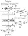
- the processing by the power controller 22 is started after the start condition of the engine 14 is established.
- the clutch 24 is switched to the connected state and the engine 14 is started (step S1).
- step S2 If it is determined in step S2 that the charging amount is equal to or greater than the specified value, the clutch 24 is switched to the switching state (step S3), the electric motor 16 is driven by the power of the battery 19 (step S4), and the engine 14 is further turned on. Stop (step S5).
- the hydraulic pump 18 can be driven in a state where the engine 14 is stopped when the charge amount of the battery 19 has a margin. Therefore, fuel consumption can be improved.
- steps S3 to S5 are continuously executed until the charge amount of the battery 19 becomes less than the specified value (while NO is determined in step S6). On the other hand, when the charge amount of the battery 19 becomes less than the specified value (YES in step S6), the process returns to step S1.
- step S7 it is determined whether or not assistance by the electric motor 16 is possible. That is, in step S ⁇ b> 7, whether or not the motor 16 can assist is determined based on the charge amount of the battery 19 and the driving state of the engine 14 (including the load in the hydraulic pump 18). If it is determined in step S7 that the assist is possible, the electric motor 16 is driven by the electric power of the battery 19 (step S8). The assist of the engine 14 by the electric motor 16 in step S8 is continuously executed until it is determined that the assist is impossible (while it is determined NO in step S9).
- step S2 is repeatedly executed.
- the present invention is a power transmission device provided in a hybrid construction machine, and can store an engine, a generator capable of generating electricity by operating with the power of the engine, and electric power generated by the generator A battery, an electric motor operable by the power of the engine and electric power of the battery, a hydraulic pump connected to the electric motor to be driven by the operation of the electric motor, and the power of the engine is the generator and the electric motor
- a power transmission device comprising: the engine, the generator, and a power divider connected to the electric motor.
- a generator for power generation and an electric motor for assisting the engine are separately provided, and the generator and the electric motor are connected to the engine via a power divider.
- the power of the engine can be directly used as the power of the electric motor (hydraulic pump) while generating power with the power of the engine.
- the hydraulic pump is driven by operating the electric motor with the electric power of the battery, that is, the engine can be assisted.
- the present invention has the following effects unlike the series hybrid system. Specifically, since the power of the engine can be directly used as the power of the hydraulic pump, the output required for the electric motor can be kept small, and the electric motor can be made small. Further, when there is a surplus in engine output or when a failure occurs in the electrical system, the hydraulic pump can be driven using the engine power.
- the present invention has the following effects unlike the parallel hybrid system. Specifically, according to the present invention, the generator for power generation and the electric motor for assistance are individually provided. Therefore, by selecting a generator having a rated output corresponding to the output during power generation and selecting an electric motor having a rated output corresponding to the output during assist, power generation and assist can be performed efficiently.
- the power of the engine can be directly used as the power of the hydraulic pump, and power generation and assist can be performed efficiently.
- the power divider has a speed change mechanism that changes the rotational speed of the engine so that the rotational speed of the generator is higher than the rotational speed of the electric motor.
- the rotational speed of the generator is set higher than the rotational speed of the electric motor by the speed change mechanism.
- the speed change mechanism transmits the power of the engine to the generator in a state where the rotational speed of the engine is increased, and the power divider maintains the rotational speed of the engine while maintaining the rotational speed of the engine. It is preferable to transmit engine power to the electric motor.
- the rotational speed of the generator increases and the rotational speed of the electric motor is maintained with reference to the rotational speed of the engine.
- the hydraulic pump used in the construction machine in which the engine and the hydraulic pump are directly connected can be used without changing the specification while reducing the size of the generator and generating efficiency. Therefore, the hydraulic pump can be shared in a plurality of types of construction machines.
- a clutch capable of switching operation, a charge amount detector capable of detecting the charge amount of the battery, and when the charge amount of the battery detected by the charge amount detector is equal to or greater than a predetermined value, It is preferable to include power control means for switching, operating the electric motor with electric power of the battery, and further stopping the engine.
- the engine when there is a margin in the charge amount of the battery, the engine can be stopped and the hydraulic pump can be driven only by the output of the electric motor. Thereby, reduction of fuel consumption can be aimed at.
- the power control means includes a clutch switching member for switching the clutch between a connected state and a disconnected state, an electric motor controller that controls driving of the electric motor, and an engine that controls driving of the engine.
- a controller and a power controller that outputs a control command to the clutch switching member, the electric motor controller, and the engine controller based on a detection result from the charge amount detector; can do.
- the present invention also provides a hybrid construction machine comprising a hydraulic actuator and the power transmission device having a hydraulic pump that drives the hydraulic actuator.
- the power of the engine can be directly used as power of the hydraulic pump, and power generation and assist can be performed efficiently.
- Hybrid excavator (hybrid construction machine) DESCRIPTION OF SYMBOLS 4 Power transmission device 14 Engine 15 Generator 16 Electric motor 17 Power divider 18 Hydraulic pump 19 Battery 20 Generator controller 21 Motor controller 22 Power controller 23 Speed increasing mechanism (transmission mechanism) 24 Clutch 25 Clutch switching member 26 Charge amount detector 27 Engine controller
Landscapes
- Engineering & Computer Science (AREA)
- Mechanical Engineering (AREA)
- Transportation (AREA)
- Chemical & Material Sciences (AREA)
- Combustion & Propulsion (AREA)
- Power Engineering (AREA)
- Mining & Mineral Resources (AREA)
- Civil Engineering (AREA)
- General Engineering & Computer Science (AREA)
- Structural Engineering (AREA)
- Automation & Control Theory (AREA)
- Operation Control Of Excavators (AREA)
- Hybrid Electric Vehicles (AREA)
- Fluid-Pressure Circuits (AREA)
- Connection Of Motors, Electrical Generators, Mechanical Devices, And The Like (AREA)
Priority Applications (3)
| Application Number | Priority Date | Filing Date | Title |
|---|---|---|---|
| EP13768052.6A EP2832567B1 (fr) | 2012-03-26 | 2013-03-06 | Dispositif de transmission de puissance et engin de construction hybride avec un tel dispositif |
| US14/387,436 US9637890B2 (en) | 2012-03-26 | 2013-03-06 | Power transmission device and hybrid construction machine provided therewith |
| CN201380016991.6A CN104220287B (zh) | 2012-03-26 | 2013-03-06 | 动力传递装置以及具备该动力传递装置的混合动力工程机械 |
Applications Claiming Priority (2)
| Application Number | Priority Date | Filing Date | Title |
|---|---|---|---|
| JP2012-068717 | 2012-03-26 | ||
| JP2012068717A JP5970898B2 (ja) | 2012-03-26 | 2012-03-26 | 動力伝達装置及びこれを備えたハイブリッド建設機械 |
Publications (1)
| Publication Number | Publication Date |
|---|---|
| WO2013145575A1 true WO2013145575A1 (fr) | 2013-10-03 |
Family
ID=49258895
Family Applications (1)
| Application Number | Title | Priority Date | Filing Date |
|---|---|---|---|
| PCT/JP2013/001410 Ceased WO2013145575A1 (fr) | 2012-03-26 | 2013-03-06 | Dispositif de transmission de puissance et engins de chantier hybrides équipés de celui-ci |
Country Status (5)
| Country | Link |
|---|---|
| US (1) | US9637890B2 (fr) |
| EP (1) | EP2832567B1 (fr) |
| JP (1) | JP5970898B2 (fr) |
| CN (1) | CN104220287B (fr) |
| WO (1) | WO2013145575A1 (fr) |
Families Citing this family (26)
| Publication number | Priority date | Publication date | Assignee | Title |
|---|---|---|---|---|
| JP6027790B2 (ja) * | 2012-06-29 | 2016-11-16 | 株式会社タダノ | 作業車両 |
| CN103587400B (zh) * | 2013-11-08 | 2017-01-18 | 杭州爱知工程车辆有限公司 | 一种静音动力装置 |
| CN105350597B (zh) * | 2015-10-27 | 2017-12-15 | 湖南工程学院 | 一种并联式混合动力挖掘机动力系统控制方法 |
| US10023195B2 (en) | 2016-08-11 | 2018-07-17 | Caterpillar Inc. | Powertrain operation and regulation |
| CN106368258B (zh) * | 2016-11-16 | 2019-04-09 | 临沂常泰工程机械有限公司 | 电动装载机 |
| US10989052B2 (en) * | 2017-02-14 | 2021-04-27 | Kolberg-Pioneer, Inc. | Apparatus and method for a dual power system |
| CN109677281A (zh) * | 2017-10-18 | 2019-04-26 | 江苏卡威汽车工业集团股份有限公司 | 一种增程式电动汽车动力系统 |
| JP6944426B2 (ja) * | 2018-09-05 | 2021-10-06 | 株式会社日立建機ティエラ | 電動式建設機械 |
| CN111319474B (zh) * | 2018-12-12 | 2022-01-28 | 中车唐山机车车辆有限公司 | 内燃车辆的传动控制系统 |
| US11511642B2 (en) | 2019-04-05 | 2022-11-29 | Oshkosh Corporation | Electric concrete vehicle systems and methods |
| US11137052B2 (en) | 2019-08-29 | 2021-10-05 | Deere & Company | Transmission assembly with integrated CVP |
| US10981024B1 (en) | 2019-10-11 | 2021-04-20 | Oshkosh Corporation | Hybrid fire fighting vehicle |
| US11351983B2 (en) | 2019-10-31 | 2022-06-07 | Deere & Company | Power control system with transmission transient boost function |
| CN112224015A (zh) * | 2019-11-01 | 2021-01-15 | 荆门市亿美工业设计有限公司 | 一种机械式自动扭矩控制动能耦合器 |
| CN110816262B (zh) * | 2019-11-01 | 2021-04-09 | 荆门市亿美工业设计有限公司 | 自动回收动能的汽车及动能回收方法 |
| CN110936948B (zh) * | 2019-12-02 | 2021-04-02 | 北京智远弘业机器人科技有限公司 | 一种不同类型的执行单元的功率分配方法及装置 |
| US11846085B2 (en) | 2020-02-17 | 2023-12-19 | Deere & Company | Energy management system for a hybrid vehicle with an electrically powered hydraulic system |
| US11572672B2 (en) * | 2020-02-21 | 2023-02-07 | Deere & Company | Method to decouple engine speed from hydraulic pump speed through an electric motor driven variator |
| US11325459B2 (en) | 2020-10-09 | 2022-05-10 | Deere & Company | Low profile transmission assembly with integrated CVP |
| US11613246B2 (en) | 2021-01-21 | 2023-03-28 | Deere & Company | Power control system with engine throttle shift function |
| US11628822B2 (en) | 2021-02-09 | 2023-04-18 | Deere & Company | Power control system with stall prevention clutch modulation function |
| US11820361B2 (en) | 2021-11-30 | 2023-11-21 | Deere & Company | Transmission assembly with electrical machine unit for improved shift quality |
| US11585412B1 (en) | 2021-12-22 | 2023-02-21 | Deere & Company | Electronically-variable, dual-path power shift transmission for work vehicles |
| US11607948B1 (en) | 2021-12-22 | 2023-03-21 | Deere & Company | Electronically-variable power shift transmission for work vehicles |
| US11913528B1 (en) | 2022-10-28 | 2024-02-27 | Deere & Company | Multi-mode continuously variable transmission assembly with drop set arrangement |
| US20240375637A1 (en) * | 2023-05-08 | 2024-11-14 | Caterpillar Paving Products Inc. | Control of a hybrid powertrain system |
Citations (4)
| Publication number | Priority date | Publication date | Assignee | Title |
|---|---|---|---|---|
| JP2001329573A (ja) | 2000-05-23 | 2001-11-30 | Kobelco Contstruction Machinery Ltd | 建設機械 |
| JP2003009308A (ja) * | 2001-06-22 | 2003-01-10 | Kobelco Contstruction Machinery Ltd | 作業機械 |
| JP2005194978A (ja) * | 2004-01-09 | 2005-07-21 | Kobelco Contstruction Machinery Ltd | 作業機械 |
| JP2007146620A (ja) * | 2005-11-07 | 2007-06-14 | Kobelco Contstruction Machinery Ltd | 旋回式作業機械 |
Family Cites Families (40)
| Publication number | Priority date | Publication date | Assignee | Title |
|---|---|---|---|---|
| CN1159519C (zh) | 1998-12-24 | 2004-07-28 | 丰田自动车株式会社 | 内燃机的输出状态检测装置 |
| JP3877901B2 (ja) * | 1999-03-31 | 2007-02-07 | コベルコ建機株式会社 | ショベル |
| WO2001000935A1 (fr) * | 1999-06-28 | 2001-01-04 | Kobelco Construction Machinery Co., Ltd. | Dispositif de commande d'une machine de chantier |
| JP2001069611A (ja) * | 1999-08-27 | 2001-03-16 | Honda Motor Co Ltd | ハイブリッド車両のバッテリ制御装置 |
| JP3460665B2 (ja) * | 2000-03-06 | 2003-10-27 | 日産自動車株式会社 | ハイブリッド車両の自動変速機 |
| DE60141137D1 (de) | 2000-05-23 | 2010-03-11 | Kobelco Constr Machinery Ltd | Baumaschine |
| US20040201365A1 (en) * | 2001-04-05 | 2004-10-14 | Electrovaya Inc. | Energy storage device for loads having variable power rates |
| JP3859982B2 (ja) * | 2001-04-27 | 2006-12-20 | 株式会社神戸製鋼所 | ハイブリッド建設機械の電力制御装置 |
| JP4179465B2 (ja) * | 2002-07-31 | 2008-11-12 | 株式会社小松製作所 | 建設機械 |
| WO2004029435A1 (fr) * | 2002-09-26 | 2004-04-08 | Hitachi Construction Machinery Co., Ltd. | Controleur de force motrice d'amorçage d'un engin de travaux |
| JP4072898B2 (ja) * | 2002-11-21 | 2008-04-09 | 株式会社小松製作所 | ハイブリッド式建設機械の機器配置構造 |
| JP4042634B2 (ja) * | 2003-06-05 | 2008-02-06 | 株式会社デンソー | 流体機械 |
| JP2005237178A (ja) | 2004-02-23 | 2005-09-02 | Kobelco Contstruction Machinery Ltd | 作業機械の動力源装置 |
| US7619378B2 (en) * | 2004-07-05 | 2009-11-17 | Komatsu Ltd. | Rotation control device, rotation control method and construction machine |
| JP2006273516A (ja) * | 2005-03-29 | 2006-10-12 | Toyota Industries Corp | ハイブリッド型フォークリフト |
| JP2006273517A (ja) * | 2005-03-29 | 2006-10-12 | Toyota Industries Corp | ハイブリッド型フォークリフト |
| WO2006132031A1 (fr) * | 2005-06-06 | 2006-12-14 | Shin Caterpillar Mitsubishi Ltd. | Dispositif d’entraînement pour rotation, et machine de travail |
| JP2006336845A (ja) * | 2005-06-06 | 2006-12-14 | Shin Caterpillar Mitsubishi Ltd | 作業機械 |
| JP2007040279A (ja) * | 2005-08-05 | 2007-02-15 | Toyota Motor Corp | 内燃機関の制御装置 |
| US7388301B2 (en) | 2005-10-12 | 2008-06-17 | Kobelco Construction Machinery Co., Ltd. | Construction machine |
| US7556120B2 (en) * | 2006-05-25 | 2009-07-07 | Gm Global Technology Operations, Inc. | Method and apparatus to control hydraulic pressure in an electro-mechanical transmission |
| JP4052483B2 (ja) * | 2006-05-30 | 2008-02-27 | 三菱重工業株式会社 | 作業車両 |
| EP1961869B1 (fr) * | 2007-02-21 | 2018-10-10 | Kobelco Construction Machinery Co., Ltd. | Dispositif de contrôle de rotation et machine de travail correspondante |
| JP5149826B2 (ja) * | 2009-01-29 | 2013-02-20 | 住友重機械工業株式会社 | ハイブリッド式作業機械及びサーボ制御システム |
| KR101334234B1 (ko) * | 2009-06-19 | 2013-11-29 | 스미도모쥬기가이고교 가부시키가이샤 | 하이브리드형 건설기계 및 하이브리드형 건설기계의 제어방법 |
| JP5198661B2 (ja) * | 2009-06-25 | 2013-05-15 | 住友重機械工業株式会社 | ハイブリッド型作業機械及び作業機械の制御方法 |
| JP5365432B2 (ja) * | 2009-09-07 | 2013-12-11 | コベルコ建機株式会社 | 建設機械の漏電検出装置 |
| SE0951034A1 (sv) * | 2009-12-29 | 2011-06-30 | Bae Systems Haegglunds Ab | Elhybridsystem |
| DE102010004596A1 (de) | 2010-01-13 | 2011-07-14 | HYTRAC GmbH, 45139 | Hybridantrieb für mobile Arbeitsmaschinen sowie Verfahren zur Steuerung eines Getriebes für einen Hybridantrieb |
| JP5227981B2 (ja) | 2010-01-22 | 2013-07-03 | 日立建機株式会社 | ハイブリッド式作業機械 |
| JP5682744B2 (ja) * | 2010-03-17 | 2015-03-11 | コベルコ建機株式会社 | 作業機械の旋回制御装置 |
| JP5703587B2 (ja) * | 2010-04-14 | 2015-04-22 | コベルコ建機株式会社 | ハイブリッド作業機械 |
| US20120104770A1 (en) * | 2010-10-29 | 2012-05-03 | Jacob Sajan Joseph | Regenerative power charging for electricity generation systems |
| JP5747533B2 (ja) * | 2011-02-02 | 2015-07-15 | コベルコ建機株式会社 | 旋回式作業機械 |
| JP5244214B2 (ja) * | 2011-05-18 | 2013-07-24 | 株式会社小松製作所 | 作業機械のエンジン制御装置およびそのエンジン制御方法 |
| US8909434B2 (en) * | 2011-06-29 | 2014-12-09 | Caterpillar, Inc. | System and method for controlling power in machine having electric and/or hydraulic devices |
| JP5841399B2 (ja) * | 2011-10-14 | 2016-01-13 | 日立建機株式会社 | ハイブリッド式建設機械及びその制御方法 |
| DE202011107327U1 (de) * | 2011-10-28 | 2012-02-02 | Atlas Weyhausen Gmbh | Nutzfahrzeug mit einem Hybridantrieb |
| JP5867039B2 (ja) * | 2011-12-09 | 2016-02-24 | コベルコ建機株式会社 | ハイブリッド建設機械 |
| JP6051857B2 (ja) * | 2012-12-28 | 2016-12-27 | コベルコ建機株式会社 | 建設機械 |
-
2012
- 2012-03-26 JP JP2012068717A patent/JP5970898B2/ja not_active Expired - Fee Related
-
2013
- 2013-03-06 WO PCT/JP2013/001410 patent/WO2013145575A1/fr not_active Ceased
- 2013-03-06 US US14/387,436 patent/US9637890B2/en not_active Expired - Fee Related
- 2013-03-06 EP EP13768052.6A patent/EP2832567B1/fr not_active Not-in-force
- 2013-03-06 CN CN201380016991.6A patent/CN104220287B/zh not_active Expired - Fee Related
Patent Citations (4)
| Publication number | Priority date | Publication date | Assignee | Title |
|---|---|---|---|---|
| JP2001329573A (ja) | 2000-05-23 | 2001-11-30 | Kobelco Contstruction Machinery Ltd | 建設機械 |
| JP2003009308A (ja) * | 2001-06-22 | 2003-01-10 | Kobelco Contstruction Machinery Ltd | 作業機械 |
| JP2005194978A (ja) * | 2004-01-09 | 2005-07-21 | Kobelco Contstruction Machinery Ltd | 作業機械 |
| JP2007146620A (ja) * | 2005-11-07 | 2007-06-14 | Kobelco Contstruction Machinery Ltd | 旋回式作業機械 |
Non-Patent Citations (1)
| Title |
|---|
| See also references of EP2832567A4 |
Also Published As
| Publication number | Publication date |
|---|---|
| US20150090506A1 (en) | 2015-04-02 |
| JP2013199202A (ja) | 2013-10-03 |
| EP2832567A1 (fr) | 2015-02-04 |
| EP2832567B1 (fr) | 2017-12-27 |
| CN104220287A (zh) | 2014-12-17 |
| JP5970898B2 (ja) | 2016-08-17 |
| EP2832567A4 (fr) | 2015-08-05 |
| US9637890B2 (en) | 2017-05-02 |
| CN104220287B (zh) | 2016-10-19 |
Similar Documents
| Publication | Publication Date | Title |
|---|---|---|
| JP5970898B2 (ja) | 動力伝達装置及びこれを備えたハイブリッド建設機械 | |
| JP5149826B2 (ja) | ハイブリッド式作業機械及びサーボ制御システム | |
| KR101256483B1 (ko) | 하이브리드형 작업기계 | |
| JP5974014B2 (ja) | ハイブリッド駆動式の油圧作業機械 | |
| WO2011145585A1 (fr) | Engin de construction hybride | |
| JP2018087487A (ja) | ショベル | |
| EP2657411B1 (fr) | Appareil de commande de braquage destiné à un engin de construction hybride | |
| KR101549117B1 (ko) | 하이브리드식 작업기계 및 그 제어방법 | |
| EP2620555B1 (fr) | Dispositif de commande d'entraînement en rotation | |
| JP5583901B2 (ja) | ハイブリッド型建設機械 | |
| JP7683169B2 (ja) | 作業機械 | |
| JP5443440B2 (ja) | ハイブリッド式建設機械及びこれに用いるカップリング装置 | |
| JP2008297031A (ja) | 産業車両 | |
| JP2010047125A (ja) | ハイブリッド建設機械の走行制御回路 | |
| JP2016217087A (ja) | 建設機械 | |
| JP5516266B2 (ja) | ハイブリッド型作業機 | |
| JP7479122B2 (ja) | 作業機械 | |
| JP2022178132A (ja) | 作業機械 | |
| KR101998379B1 (ko) | 하이브리드 쇼벨 및 하이브리드 쇼벨의 제어방법 | |
| JP2020117869A (ja) | 作業機械 | |
| KR20100074562A (ko) | 건설기계의 선회장치 | |
| JP2018148696A (ja) | 作業機械 |
Legal Events
| Date | Code | Title | Description |
|---|---|---|---|
| 121 | Ep: the epo has been informed by wipo that ep was designated in this application |
Ref document number: 13768052 Country of ref document: EP Kind code of ref document: A1 |
|
| WWE | Wipo information: entry into national phase |
Ref document number: 14387436 Country of ref document: US |
|
| WWE | Wipo information: entry into national phase |
Ref document number: 2013768052 Country of ref document: EP |
|
| NENP | Non-entry into the national phase |
Ref country code: DE |