WO2013145754A1 - Procédé de fabrication d'une lentille plastique et procédé de fabrication d'un moule pour la formation d'une lentille optique - Google Patents
Procédé de fabrication d'une lentille plastique et procédé de fabrication d'un moule pour la formation d'une lentille optique Download PDFInfo
- Publication number
- WO2013145754A1 WO2013145754A1 PCT/JP2013/002120 JP2013002120W WO2013145754A1 WO 2013145754 A1 WO2013145754 A1 WO 2013145754A1 JP 2013002120 W JP2013002120 W JP 2013002120W WO 2013145754 A1 WO2013145754 A1 WO 2013145754A1
- Authority
- WO
- WIPO (PCT)
- Prior art keywords
- mold
- molding
- insert
- glass substrate
- cavity
- Prior art date
- Legal status (The legal status is an assumption and is not a legal conclusion. Google has not performed a legal analysis and makes no representation as to the accuracy of the status listed.)
- Ceased
Links
Images




Classifications
-
- B—PERFORMING OPERATIONS; TRANSPORTING
- B29—WORKING OF PLASTICS; WORKING OF SUBSTANCES IN A PLASTIC STATE IN GENERAL
- B29C—SHAPING OR JOINING OF PLASTICS; SHAPING OF MATERIAL IN A PLASTIC STATE, NOT OTHERWISE PROVIDED FOR; AFTER-TREATMENT OF THE SHAPED PRODUCTS, e.g. REPAIRING
- B29C45/00—Injection moulding, i.e. forcing the required volume of moulding material through a nozzle into a closed mould; Apparatus therefor
- B29C45/0001—Injection moulding, i.e. forcing the required volume of moulding material through a nozzle into a closed mould; Apparatus therefor characterised by the choice of material
-
- B—PERFORMING OPERATIONS; TRANSPORTING
- B29—WORKING OF PLASTICS; WORKING OF SUBSTANCES IN A PLASTIC STATE IN GENERAL
- B29C—SHAPING OR JOINING OF PLASTICS; SHAPING OF MATERIAL IN A PLASTIC STATE, NOT OTHERWISE PROVIDED FOR; AFTER-TREATMENT OF THE SHAPED PRODUCTS, e.g. REPAIRING
- B29C45/00—Injection moulding, i.e. forcing the required volume of moulding material through a nozzle into a closed mould; Apparatus therefor
- B29C45/17—Component parts, details or accessories; Auxiliary operations
- B29C45/72—Heating or cooling
- B29C45/73—Heating or cooling of the mould
-
- B—PERFORMING OPERATIONS; TRANSPORTING
- B29—WORKING OF PLASTICS; WORKING OF SUBSTANCES IN A PLASTIC STATE IN GENERAL
- B29C—SHAPING OR JOINING OF PLASTICS; SHAPING OF MATERIAL IN A PLASTIC STATE, NOT OTHERWISE PROVIDED FOR; AFTER-TREATMENT OF THE SHAPED PRODUCTS, e.g. REPAIRING
- B29C45/00—Injection moulding, i.e. forcing the required volume of moulding material through a nozzle into a closed mould; Apparatus therefor
- B29C45/17—Component parts, details or accessories; Auxiliary operations
- B29C45/76—Measuring, controlling or regulating
- B29C45/78—Measuring, controlling or regulating of temperature
-
- B—PERFORMING OPERATIONS; TRANSPORTING
- B29—WORKING OF PLASTICS; WORKING OF SUBSTANCES IN A PLASTIC STATE IN GENERAL
- B29D—PRODUCING PARTICULAR ARTICLES FROM PLASTICS OR FROM SUBSTANCES IN A PLASTIC STATE
- B29D11/00—Producing optical elements, e.g. lenses or prisms
-
- B—PERFORMING OPERATIONS; TRANSPORTING
- B29—WORKING OF PLASTICS; WORKING OF SUBSTANCES IN A PLASTIC STATE IN GENERAL
- B29D—PRODUCING PARTICULAR ARTICLES FROM PLASTICS OR FROM SUBSTANCES IN A PLASTIC STATE
- B29D11/00—Producing optical elements, e.g. lenses or prisms
- B29D11/00009—Production of simple or compound lenses
- B29D11/0048—Moulds for lenses
-
- B—PERFORMING OPERATIONS; TRANSPORTING
- B29—WORKING OF PLASTICS; WORKING OF SUBSTANCES IN A PLASTIC STATE IN GENERAL
- B29C—SHAPING OR JOINING OF PLASTICS; SHAPING OF MATERIAL IN A PLASTIC STATE, NOT OTHERWISE PROVIDED FOR; AFTER-TREATMENT OF THE SHAPED PRODUCTS, e.g. REPAIRING
- B29C2945/00—Indexing scheme relating to injection moulding, i.e. forcing the required volume of moulding material through a nozzle into a closed mould
-
- B—PERFORMING OPERATIONS; TRANSPORTING
- B29—WORKING OF PLASTICS; WORKING OF SUBSTANCES IN A PLASTIC STATE IN GENERAL
- B29C—SHAPING OR JOINING OF PLASTICS; SHAPING OF MATERIAL IN A PLASTIC STATE, NOT OTHERWISE PROVIDED FOR; AFTER-TREATMENT OF THE SHAPED PRODUCTS, e.g. REPAIRING
- B29C45/00—Injection moulding, i.e. forcing the required volume of moulding material through a nozzle into a closed mould; Apparatus therefor
- B29C45/17—Component parts, details or accessories; Auxiliary operations
- B29C45/46—Means for plasticising or homogenising the moulding material or forcing it into the mould
- B29C45/56—Means for plasticising or homogenising the moulding material or forcing it into the mould using mould parts movable during or after injection, e.g. injection-compression moulding
- B29C45/561—Injection-compression moulding
-
- B—PERFORMING OPERATIONS; TRANSPORTING
- B29—WORKING OF PLASTICS; WORKING OF SUBSTANCES IN A PLASTIC STATE IN GENERAL
- B29L—INDEXING SCHEME ASSOCIATED WITH SUBCLASS B29C, RELATING TO PARTICULAR ARTICLES
- B29L2011/00—Optical elements, e.g. lenses, prisms
- B29L2011/0016—Lenses
-
- G—PHYSICS
- G02—OPTICS
- G02B—OPTICAL ELEMENTS, SYSTEMS OR APPARATUS
- G02B1/00—Optical elements characterised by the material of which they are made; Optical coatings for optical elements
- G02B1/04—Optical elements characterised by the material of which they are made; Optical coatings for optical elements made of organic materials, e.g. plastics
- G02B1/041—Lenses
Definitions
- the present invention relates to a method for producing a plastic lens and a method for producing an optical lens mold.
- plastic lenses for spectacles are manufactured by an injection molding method using a thermoplastic resin such as a polycarbonate resin or a methacrylic resin, and a plastic having a complicated optical surface shape like a progressive power lens. Even with a lens, high-precision molding is possible by transferring the cavity shape of the mold.
- a thermoplastic resin such as a polycarbonate resin or a methacrylic resin
- Patent Document 1 discloses that a plastic lens is molded with high accuracy by controlling the mold temperature by inserting a high-frequency heating means into the mold and heating the mold in the mold open state during mold clamping. A method is disclosed.
- Patent Document 2 discloses a method in which a mold is vibrated by ultrasonic waves when injecting and filling molten resin into the cavity.
- Patent Document 3 discloses a method of injecting carbon dioxide between the resin filled in the cavity and the cavity surface.
- Patent Document 4 discloses an example of such injection compression molding. Yes.
- the injection compression molding method by further compressing the resin injected and filled in the cavity of the mold, the shrinkage of the molten resin can be corrected to obtain uniform and high shape accuracy. Molding is possible.
- the injection mold used in the injection compression molding method of Patent Document 4 is an insert mold as an optical lens molding mold for molding the optical surface of a lens, which can be exchanged according to the type of lens to be molded. These are accommodated in insert guide members provided in each of the movable mold and the fixed mold, thereby forming a lens molding cavity. Insert molds as optical lens molds are usually formed using steel materials such as maraging steel and beryllium copper alloy, but for reasons such as being able to mold a smoother and more accurate optical surface. When molding a plastic lens, it may be more convenient to use a glass mold. For this reason, there is known an optical lens molding die in which a glass base material on which a molding surface for molding an optical surface of a lens is formed is bonded to a metal base (see Patent Document 5).
- the steel material used for the mold has a very large thermal diffusivity compared to the resin, so cooling and solidification rapidly proceeds when the molten resin injected and filled into the mold cavity contacts the mold surface.
- the temperature is controlled so that the temperature of the molding die when the molten resin is injected and filled becomes high. Is effective.
- Patent Document 1 since heating can be performed only while the mold is opened, temperature control is required in consideration of a temperature change from when the mold is closed until filling is completed. Actually, it is not easy to perform the temperature control with high accuracy. Further, the methods disclosed in Patent Documents 2 and 3 do not increase the temperature of the mold, but the method disclosed in Patent Document 2 uses a mold structure or ultrasonic wave for applying vibration to the mold. A generator is required, and in the method disclosed in Patent Document 3, in order to inject carbon dioxide, the mold structure must be changed in consideration of the flow path. For this reason, there is a problem that it is difficult to apply just by diverting an existing injection molding apparatus, and a new capital investment is required.
- the present invention has been made in view of the circumstances as described above, and even if the temperature of the molding die when injecting and filling the molten resin into the cavity is set low, the transferability does not decrease, and the cooling is performed.
- a method for manufacturing a plastic lens that can shorten the time required to improve productivity and can be easily applied to an existing injection molding apparatus, and a lens suitable for carrying out such a method for manufacturing a plastic lens.
- an optical lens molding die formed by joining a glass base material on which a molding surface for molding an optical surface is formed to a metal pedestal it is possible to effectively avoid breakage of the glass base material in the state of use. It is an object of the present invention to provide a method for producing an optical lens mold that can be used.
- the method of manufacturing a plastic lens according to the present invention includes a step of injecting and filling a molten raw resin into a cavity formed between a pair of split molds to manufacture a plastic lens having a predetermined lens shape.
- a molding surface that forms the cavity is formed by a heat insulating material made of a glass material, and the raw material resin that has flowed into the cavity fills the cavity and is completely filled.
- the temperature of the molding surface is controlled so as not to exceed the glass transition temperature of the raw material resin.
- the method for producing an optical lens molding die according to the present invention is an optical lens molding in which a glass substrate on which a molding surface for molding a plastic lens having a predetermined lens shape is formed is bonded to a metal base.
- a method for manufacturing a mold wherein the glass substrate is formed to have a smaller diameter than the pedestal, and an assembly jig is closely attached to the outer peripheral surface of the pedestal, and the assembly jig and the glass substrate Between the glass substrate and the pedestal, the glass substrate is overlapped and joined to the pedestal in a state where a filler formed with a thickness matching the diameter difference between the glass substrate and the pedestal is sandwiched.
- productivity can be increased by shortening a molding cycle while keeping transferability intact.
- an optical lens molding die obtained by joining a glass substrate on which a molding surface for molding an optical surface of a lens is formed to a metal base. When used to mold a plastic lens, breakage of the glass substrate can be effectively avoided.
- FIG. 3 is a cross-sectional view taken along line AA in FIG. 2.
- FIG. 3 is a sectional view taken along line BB in FIG. It is a principal part expanded sectional view which expands and shows the circumference
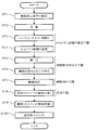
- FIG. 7 is a cross-sectional view taken along the line CC of FIG. It is a flowchart which shows each step in embodiment of the manufacturing method of the plastic lens which concerns on this invention. It is explanatory drawing which shows an example of the method of measuring the surface temperature of a molding surface.
- FIG. 1 is an explanatory view showing an example of an injection molding apparatus, and the plastic lens manufacturing method according to this embodiment can be implemented by suitably using such an injection molding apparatus.
- the injection molding apparatus shown in FIG. 1 includes a mold 50 having a movable mold 1 and a fixed mold 2 as a pair of split molds divided by a parting line PL, and opening / closing and mold clamping of the mold 50 by a toggle link mechanism 65.
- An injection apparatus 80 provided in the injection molding apparatus shown in FIG. 1 has a heating cylinder 82 having a nozzle 85 formed at the tip. Inside the heating cylinder 82, a screw whose rotation and forward / backward movement are controlled by the drive unit 84 is disposed.
- a hopper 81 for feeding pellet-shaped raw resin into the heating cylinder 82 is connected to the proximal end side of the heating cylinder 82.
- the raw material resin charged into the heating cylinder 82 from the hopper 81 is melted and kneaded by shearing heat and heating from the heater provided in the heating cylinder 82 while being sheared and pulverized by a screw rotating in the heating cylinder 82.
- the mold clamping device 60 has a plurality of tie bars 63 installed between a fixed die plate 61 and a rear plate 62 erected on a gantry 66 at a predetermined interval, and a movable die plate. 64 is configured to be moved by being guided by the tie bar 63.
- a molding die 50 is attached between the fixed die plate 61 and the movable die plate 64, and a toggle link mechanism 65 is attached between the rear plate 62 and the movable die plate 64.
- the toggle link mechanism 65 is driven, the movable die plate 64 is guided by the tie bar 63 to advance and retreat, and accordingly, the mold 50 is opened and closed and the mold is clamped.
- the toggle link mechanism 65 is configured such that the screwed crosshead 73 moves along the ball screw 72 as the ball screw 72 connected to a motor (not shown) rotates.
- the toggle links 71A and 71B extend linearly by the connecting links 74A and 74B, and the movable die plate 64 moves so as to approach the fixed die plate 61 (advance).
- the toggle links 71A and 71B are bent inward by the connecting links 74A and 74B so that the movable die plate 64 is separated from the fixed die plate 61. Move (retreat).
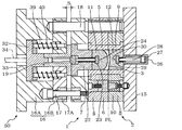
- FIG. 2 is a cross-sectional view showing a cross section of the molding die 50 shown in FIG. 1 cut along a plane perpendicular to the paper surface passing through the central axis, and shows an initial state in which the die is closed.
- 3 is a cross-sectional view taken along the line AA in FIG. 2
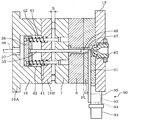
- FIG. 4 is a cross-sectional view taken along the line BB in FIG. 2
- FIG. 5 is an enlarged cross-sectional view of the main part showing the periphery of the cavity 3 in FIG. FIG.
- a pair of split molds, a mold 50 and a movable mold 1 and a fixed mold 2 are sandwiched between two movable cavities 3 for molding a plastic lens of a predetermined shape and a gate G.
- a runner 49 as a resin flow path connected to each cavity 3 is formed.
- a sprue bush 47 that forms a sprue 48 connected to the runner 49 at a right angle is attached to the template 10 of the fixed mold 2.
- the mold body 4 of the movable mold 1 has two insert guide members 5 and mold plates 6 and 7 for holding them. Inside the insert guide member 5, an insert mold 11 as a cavity forming member is accommodated so as to be slidable in a direction perpendicular to the parting line PL.
- the mold body 8 of the fixed mold 2 includes two insert guide members 9 and a template 10, and the insert guide member 9 is held by the template 10 and the mold attachment member 15. Inside the insert guide member 9, an insert mold 12 as a cavity forming member is accommodated so as to be slidable in a direction perpendicular to the parting line PL.
- the insert guide members 5 and 9, the insert molds 11 and 12, and the mold plates 6 and 10 are provided with a circulation mechanism for circulating a temperature control fluid supplied from a mold temperature control device (not shown).
- a molding die 50 having such a movable die 1 and a fixed die 2 includes an insert die 11 on the movable die 1 side and an insert die 12 on the fixed die 2 side between the movable die 1 and the fixed die 2.
- a cavity 3 including a molding surface formed in each is formed.
- the cavity 3 is formed corresponding to the shape of the plastic lens to be molded, and the molding surfaces of the insert molds 11 and 12 forming the cavity 3 are formed by heat insulating materials 11a and 12a made of a glass material. Yes.
- the molding surface corresponding to one optical surface of the plastic lens to be molded is made of a glass material. It is formed in the glass base material 11a as a heat insulating material, and the insert metal mold
- the insert mold 12 on the fixed mold 2 side has a molding surface corresponding to the other optical surface of the plastic lens to be molded (in the example shown, a convex surface) as a heat insulating material made of a glass material.
- An insert mold 12 is formed by bonding the glass substrate 12a to an insert body 12b as a base, which is formed on the glass substrate 12a (see FIG. 5).
- the insert molds 11 and 12 as such optical lens molds are manufactured in the following procedure. Since the insert mold 11 on the movable mold 1 side and the insert mold 12 on the fixed mold 2 side can be manufactured in the same procedure, in the following example, the insert mold 11 on the movable mold 1 side is used. The case of manufacturing will be described.
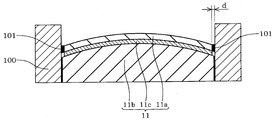
- FIG. 6 is an explanatory diagram for explaining an example of a method for manufacturing an optical lens molding die according to the present embodiment, and FIG. 7 is a cross-sectional view taken along the line CC of FIG.
- the insert body 11b is positioned for positioning.
- the assembling jig 100 is installed in close contact with the outer peripheral surface.
- three assembling jigs 100 are installed at equal intervals along the outer peripheral surface of the insert main body 11b. It is preferable to install three or more assembly members 100 so that the glass substrate 11a and the insert body 11b are not easily displaced.
- the assembly member 100 is an annular member that surrounds the entire circumference of the insert body 11b. Also good.
- each assembling jig 110 is processed with high accuracy so as to be in close contact with the outer peripheral surface of the insert main body 11b without causing a gap between the assembly jig 110 and the insert main body 11b.
- an adhesive is applied to one or both of the bonding surfaces of the glass substrate 11a and the insert main body 11b, and the bonding surfaces of both are overlapped.
- the radius of the glass substrate 11a is set to be slightly smaller than the radius of the insert body 11b, and the difference in diameter (difference between the radius of the glass substrate 11a and the radius of the insert body 11b) d is set.
- a metal tape 101 as a filler formed to have a matching thickness is sandwiched between the glass substrate 11 a and the assembly jig 100. In this state, the glass substrate 11a is overlapped and joined to the insert body 11b.
- the filler is preferably formed using a metal material so that the thickness does not change due to the pressing force when sandwiched between the glass substrate 11a and the assembly jig 100, such as stainless steel. It is preferable to use a metal tape 101 made of Further, when the metal tape 101 is sandwiched between the glass substrate 11 a and the assembly jig 100, the metal tape 101 is preferably attached to one of the glass substrate 11 a and the assembly jig 100.
- the insert mold 11 in which the glass substrate 11a and the insert main body 11b are joined via the adhesive layer 11c is completed.
- the outer peripheral surface of the glass substrate 11 a is positioned inside the outer peripheral surface of the insert main body 11 b at a constant interval d along the circumferential direction.
- the diameter difference d between the radius of the glass base materials 11a and 12a and the radius of the insert main bodies 11b and 12b can be set to, for example, 5 to 50 ⁇ m, preferably 15 to 25 ⁇ m. If it is less than the above range, the outer peripheral surfaces of the glass base materials 11a and 12a and the outer peripheral surfaces of the insert main bodies 11b and 12b are almost flush with each other, and the glass base materials 11a and 12a and the insert guide members 5 and 9 It becomes difficult to avoid contact with the inner peripheral surface. On the other hand, when the above range is exceeded, the molten resin filled in the cavity 3 enters between the inner peripheral surfaces of the glass base materials 11a and 12a and the inner peripheral surfaces of the insert guide members 5 and 9, and is molded. It is not preferable because burrs are easily generated in the plastic lens.
- Examples of the glass base materials 11a and 12a that form the molding surfaces of the insert molds 11 and 12 manufactured in this way include, for example, a crown system, a flint system, a barium system, a phosphate system, a fluorine-containing system, An amorphous glass material such as a fluorophosphate can be used. Among these, it is preferable to select and use an amorphous glass material having a thermal conductivity of 0.4 to 1.3 W / m ⁇ K as appropriate. Such an amorphous glass material is suitable for forming a molding surface that requires high accuracy and can easily obtain a mirror surface by cutting or polishing, and has excellent moldability. It is suitably used in the present invention.
- ceramics such as silicon nitride and aluminum titanate have a use as a heat insulating material.
- ceramics are not only brittle and easily cause thermal shock destruction, but also provide a mirror surface. Since high technology and cost are required, considering productivity, it is not suitable for the present invention.
- the glass substrates 11a and 12a made of such an amorphous glass material have a thickness of 3 to 4 mm so that they can sufficiently withstand the injection pressure and holding pressure at the time of injection molding in consideration of molding conditions.
- the surface treatment may be performed with tempered glass or DLC (diamond-like carbon) for the purpose of preventing damage during handling as well as during injection molding.
- thermosetting resin having a low linear expansion coefficient and excellent stability in a high temperature environment can be used as an adhesive. And what is necessary is just to join both by apply
- a thermosetting resin a sulfur-containing thermosetting resin obtained by reacting a thermosetting monomer containing sulfur is preferable.
- the sulfur-containing thermosetting resin has a low coefficient of linear expansion, is excellent in stability even in a high temperature environment, and is excellent in adhesiveness (adhesion) with a glass substrate.
- the adhesive layer can be a very thin layer.
- the sulfur-containing thermosetting resin is preferably at least one resin selected from thiourethane resins and epithio resins.
- the thiourethane resin refers to a resin obtained by reacting a polyisocyanate compound and a polythiol compound
- the epithio resin is obtained by reacting a lens raw material monomer having a compound having an epithio group as an essential component. Refers to the resin that is produced. It is particularly preferable to use a thiourethane resin as the sulfur-containing thermosetting resin because it is extremely excellent in adhesion to a glass substrate and is economical. Examples of commercially available thiourethane resins include MR series manufactured by Mitsui Chemicals, Inc., trade names “MR-6”, “MR-7”, “MR-8”, “MR-10”, “MR-20”. "MR-1746" is preferably used.
- the insert bodies 11b and 12b can be formed using a steel material such as maraging steel or beryllium copper alloy, but a steel material having a higher thermal diffusivity than the glass material used for the heat insulating materials 11a and 12a is used. Is preferred.
- the mold body 4 of the movable mold 1 is fixed to the movable die plate 64 via the mold mounting member 16, and the mold body 8 of the fixed mold 2 is mounted to the mold. It is fixed to the fixed die plate 61 via the member 15. As a result, the mold 50 is attached between the fixed die plate 61 and the movable die plate 64 of the mold clamping device 60.
- the mold mounting member 16 on the movable mold 1 side is provided with a hydraulic cylinder 19 corresponding to each of the insert molds 11, and the piston rod 21 connected to the piston 20 is connected to one end side of the hydraulic cylinder 19. It penetrates through the back insert 22 fixed to.
- a T-shaped clamp member 23 provided at the tip of each piston rod 21 is formed in a T-shaped groove 24 formed on the back surface of the insert mold 11 (the surface opposite to the surface on which the molding surface is formed). Engageable and detachable.
- the insert mold 11 can be exchanged according to the plastic lens to be molded.
- the insert mold 11 attached to the T-shaped clamp member 23 is housed inside the insert guide member 5.
- a hydraulic cylinder 26 is provided in the mold mounting member 15 on the fixed mold 2 side so as to correspond to each of the insert molds 12, and a piston rod 28 connected to the piston 27 is provided in the mold mounting member 15. It penetrates.
- a T-shaped clamp member 29 provided at the tip of each piston rod 28 is formed in a T-shaped groove 30 formed on the back surface of the insert mold 12 (the surface opposite to the surface on which the molding surface is formed). Engageable and detachable.
- the insert mold 12 can be exchanged according to the plastic lens to be molded.
- the insert mold 12 attached to the T-shaped clamp member 29 is housed inside the insert guide member 9.
- the mold body 4 of the movable mold 1 When the mold body 4 of the movable mold 1 is fixed to the movable die plate 64, the mold body 4 is bolted to the mold mounting member 16 composed of the first member 16A and the second member 16B, as shown in FIG. 17 is attached. At this time, a plurality of disc springs 17 ⁇ / b> A inserted on the outer periphery of the bolt 17 are interposed between the mold body 4 of the movable mold 1 and the mold mounting member 16, and the mold body 4 and the mold of the movable mold 1 are interposed. A gap S is formed between the mounting member 16 and the mounting member 16.
- the gap S is generated when the movable die plate 64 further advances after the molding die 50 is closed, and the die mounting member 16 guided by the guide pins 18 is pressed against the elastic force of the disc spring 17A. It is designed to be closed. Accordingly, in the illustrated example, each hydraulic cylinder 19 provided on the mold mounting member 16 presses the insert mold 11 via the back insert 22. Thereby, the volume of the cavity 3 at the time of mold clamping is made variable, and the molten resin injected and filled in the cavity 3 can be pressurized and compressed by the insert mold 11.
- the guide pin 18 protrudes toward the fixed mold 2 so as to guide the opening / closing operation of the mold 50 and is inserted through an insertion hole formed in the fixed mold 2.
- a pressure receiving member 32 is attached to the other end side of the hydraulic cylinder 19 provided on the die attaching member 16 on the movable die 1 side.
- the hydraulic cylinder 19 When the eject rod 34 inserted from the hole 33 formed in the mold attachment member 16 presses the pressure receiving member 32, the hydraulic cylinder 19, the back insert 22 and the insert mold 11 are also pressed and molded in the cavity 3. The lens is pushed out.
- an eject pin 35 is disposed at the center of the mold attachment member 16 so as to be movable back and forth in parallel with the opening / closing direction of the mold 50.
- the pressure receiving member 36 attached to the eject pin 35 When the pressure receiving member 36 attached to the eject pin 35 is pressed by the eject rod 38 inserted from the hole 37 formed in the mold attaching member 16, the eject pin 35 is pushed out. Therefore, when the mold is opened, the ejected rods 34 and 38 are advanced to take out the molded product.
- the spring force of the spring 42 wound around the outer periphery of the eject return pin 41 acts on the pressure receiving member 36 in the left direction in the figure.
- the pressure receiving member 32 has the same structure so that a leftward spring force acts in the drawing.
- the mold 50 has a nozzle shut mechanism 90 that closes the nozzle 85 of the injection device 80 as shown in FIG.
- the nozzle shut mechanism 90 has a nozzle shut pin 91 as a blocking member protruding into the sprue 48 formed by the sprue bush 47.
- the nozzle shut pin 91 is connected to a piston rod 94 of a hydraulic cylinder 93 via a connecting piece 92, and the hydraulic cylinder 93 is fixed to the mold mounting member 15 by a cylinder mounting plate 95.
- the resin pressurizing conditions are set. This is for adjusting the clamping force according to the characteristics of the plastic lens to be molded (lens shape, lens power, etc.) in advance in order to apply an appropriate pressure to the resin in the cavity 3 in advance. is there.
- the pellet-shaped raw resin charged from the hopper 81 is melted and kneaded by shearing heat and heating from the heater provided in the heating cylinder 82 while being sheared and pulverized by a screw rotating in the heating cylinder 82. While being sent, it is sent to the cylinder front chamber formed between the tip of the screw and the nozzle 85 and weighed. Here, an amount of molten resin necessary for filling the cavity 3, the runner 49, and the sprue 48 is measured.
- a thermoplastic resin such as a polycarbonate resin or an acrylic resin generally used for molding this type of plastic lens can be used.
- the mold is closed at the parting line PL.
- the toggle link mechanism 65 is driven to advance the cross head 73, the toggle links 71A and 71B extend, and the movable die plate 64 advances toward the fixed die plate 61. 50 molds are closed.
- a gap S is maintained in a state where the disc spring 17A interposed between the mold body 4 of the movable mold 1 and the mold mounting member 16 is not compressed, and the fixed mold 2 and the movable mold 1 are separated by the parting line PL. Close the mold. In this state, the gap S is set to the maximum opening amount.
- the cavity volume is set.
- the crosshead 73 is further advanced to a preset position (cavity volume setting position) from the state in which the movable mold 1 and the fixed mold 2 are brought into close contact with each other by the parting line PL.
- the toggle links 71A and 71B are extended, and the movable die plate 64 is moved toward the fixed die plate 61 and moved to the cavity expansion position.
- the cavity enlargement amount is determined by setting the crosshead position.
- the gap S of the mold 50 is reduced leaving the cavity enlargement.
- the volume (thickness) of the cavity 3 is larger than the lens volume (thickness) to be molded, that is, the thickness of the extracted molded product.
- the disc spring 17A since the disc spring 17A is compressed, some clamping force is generated as the reaction force.
- injection is performed.
- the molten resin weighed in ST2 is injected into the mold 50 through the passage of the injection nozzle 85. That is, the molten resin introduced into the heating cylinder 82 of the injection device 80 and weighed is injected. Then, molten resin is injected from a nozzle 85 formed at the tip of the heating cylinder 82 and filled into the cavity 3 through the sprue 48, the runner 49, and the gate G.
- the injection speed is controlled to be constant.
- the resin is sealed in the mold.
- the crosshead 73 is further advanced immediately before the injection filling of the molten resin is completed.
- the nozzle shut pin 91 is protruded into the sprue 48 by the nozzle shut mechanism 90 and the nozzle 85 is closed. Thereby, the filled molten resin is enclosed in the mold 50 in a compressed and pressurized state.
- the mold temperature is set so that the temperature of each part (insert mold, insert guide member, etc.) of the mold 50 is set to a temperature lower than the glass transition temperature of the raw resin according to the lens characteristics to be molded.
- the temperature of the temperature adjusting fluid is controlled by the adjusting device.
- release operation is performed.
- the crosshead 73 of the toggle link mechanism 65 is moved backward toward the rear plate 62 to open the mold 50.
- the molded product is ejected.
- the cross head 73 is retracted to the end, the distance between the movable die plate 64 and the fixed die plate 61 is maximized, and the mold 50 is divided and opened by the parting line PL.
- the eject rods 34 and 38 are advanced to take out the molded plastic lens.
- the molten resin injected and filled into the cavity 3 comes into contact with the molding surface of the mold, it is affected by the thermal diffusion of the mold, the temperature of the surface layer portion decreases, and conversely the surface temperature of the molding surface increases. . Since the thermal diffusivity of the glass material is very small as compared with a metal mold that is generally used, the surface layer of the molten resin is filled until the molten resin fills the cavity 3 and the filling is completed. The temperature can be maintained above the glass transition temperature, and the formation of the solidified layer can be delayed.
- the heat insulating effect of the glass material is used to form the glass base materials 11a and 12a within the range in which the temperature of the surface layer portion of the molten resin at the time of filling can be maintained at a temperature equal to or higher than the glass transition point. Further, the temperature of the molding surfaces of the insert molds 11 and 12 can be set lower than that of the conventional technique using a metal mold.
- the glass base materials 11a and 12a forming the respective molding surfaces of the insert dies 11 and 12 have a thermal conductivity of 0.4 to 1. It is preferable to use a glass material of 3 W / m ⁇ K. When the above range is exceeded, it tends to be difficult to obtain a sufficient heat insulating effect. On the other hand, when it is less than the above range, the heat insulation effect becomes higher than necessary, and the time required for cooling becomes longer, which is not preferable.
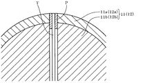
- the surface temperature of the molding surface is such that a thermocouple T is disposed in a hole opened in the molding surface (glass base material 11a, 12a) of the insert dies 11, 12,
- the measurement can be performed by filling the opening of the hole with the metal putty P and fixing the temperature measuring portion of the thermocouple T so as to be positioned in the vicinity of the molding surface.
- the molding surfaces of the insert molds 11 and 12 are formed on the glass bases 11a and 12a, thereby suppressing the temperature drop of the molten resin flowing into the cavity 3,
- the thermal diffusivity is higher than the glass material used for the glass base materials 11a and 12a. It is preferable to form the insert body using a high steel material.
- the temperature of the surface layer portion of the raw material resin remains at the glass transition temperature or higher even after the filling of the raw material resin into the cavity 3, it becomes an obstacle to shortening the molding cycle. End up. For this reason, at the timing when the cavity 3 is filled with the raw material resin and filling is completed, various molding conditions are appropriately adjusted so that the temperature of the surface layer portion of the raw material resin is lower than the glass transition temperature, and injection molding is performed. More preferably.
- the movable die plate 64 further advances, and each hydraulic cylinder 19 provided on the die attachment member 16 presses the insert die 11 via the back insert 22 to insert the insert die. 11 slides in the insert guide member 5 to compress and compress the molten resin injected and filled into the cavity 3.
- the pressure receiving member 32, the hydraulic cylinder 19, the back insert 22 and the insert mold 11 are pressed by the eject rod 34, and the insert mold 11 slides in the insert guide member 5 and is molded in the cavity 3. It is designed to push out the lens.
- the insert mold 11 even after the insert mold 11 on the movable mold 1 side is housed in the insert guide member 5, the insert mold 11 repeatedly slides in the insert guide member 5 for each molding shot.
- the outer peripheral surface of the glass substrate 11a has a constant width d along the circumferential direction and is located on the inner side of the outer peripheral surface of the insert body 11b. For this reason, even when the insert mold 11 is inclined with respect to the axial direction when sliding inside the insert guide member 5, the outer peripheral surface of the glass substrate 11 a contacts the inner peripheral surface of the insert guide member 5. This can be effectively avoided.
- the insert mold 12 on the fixed mold 2 side is provided with the glass base material 11a on which the molding surface for molding the optical surface of the lens is formed in the insert body 11b.
- a bonded optical lens mold can be used without any problem. Therefore, by forming the molding surfaces of the insert molds 11 and 12 with the glass base materials 11a and 12a, the mold temperature during the injection molding can be set low in order to shorten the molding cycle. Due to the heat insulating effect of the glass base materials 11a and 12a, the temperature drop of the molten resin flowing into the cavity 3 can be suppressed.
- each of the molding surface of the insert mold 11 on the movable mold 1 side and the molding surface of the insert mold 12 on the fixed mold 2 side has a thermal conductivity made of a crown glass material. It formed in the glass base materials 11a and 12a as a 1.1 W / m * K heat insulating material.
- polycarbonate is used as the raw material resin, the resin temperature is set to 290 ° C., and the set temperature of the molding surfaces of the insert molds 11 and 12 is set to 55 ° C.
- Example 2 A similar plastic lens was molded under the same molding conditions as in Example 1 except that the set temperature of the molding surfaces of the insert dies 11 and 12 was 85 ° C. As in Example 1, Table 1 also shows the results of evaluating the transferability by measuring the power of the central part of the molded plastic lens.
- Both the insert mold 11 on the movable mold 1 side and the insert mold 12 on the fixed mold 2 side are formed using maraging steel, the set surface temperature of the mold surface is 130 ° C., and the temperature of the mold surface is the raw material.
- a similar plastic lens was molded under the same molding conditions as in Example 1 except that the glass transition temperature of the polycarbonate used for the resin was allowed to be exceeded.
- Table 1 also shows the results of evaluating the transferability by measuring the power of the central part of the molded plastic lens.
- the molding surface set temperature was lowered to 85 ° C. (Example 2) and 55 ° C. (Example 1) with respect to the comparative example in which the molding surface temperature was set to 130 ° C.
- the cooling time could be shortened without impairing the transferability.
- a lens is molded in a semi-finished product that is thicker than the finished dimensions, and this semi-finished lens is finally processed by post-processing.
- a method of finishing in a shape for example, a plurality of types of semi-finished lenses, which are molded as different optical surface shapes on the convex side and formed with a common concave surface on the concave side, are prepared according to the user's prescription from these
- the present invention can be applied regardless of the thickness of the plastic lens to be molded, and in particular, since a plastic lens having a very thin product thickness tends to solidify during injection, although it corresponds to ultra-high speed injection molding or high temperature molding, if the present invention is applied, solidification of the resin during injection can be delayed, and it is expected that molding can be easily performed. Furthermore, when there is a very fine pattern on the optical surface, it cannot be sufficiently transferred due to solidification during injection, and it is usually handled by high temperature molding. Therefore, it is expected that molding can be easily performed.
- the present invention can be used as a technique capable of increasing productivity by shortening the time required for cooling without lowering transferability when manufacturing a plastic lens by an injection molding method.
Landscapes
- Engineering & Computer Science (AREA)
- Manufacturing & Machinery (AREA)
- Mechanical Engineering (AREA)
- Health & Medical Sciences (AREA)
- Ophthalmology & Optometry (AREA)
- Moulds For Moulding Plastics Or The Like (AREA)
- Physics & Mathematics (AREA)
- General Physics & Mathematics (AREA)
- Optics & Photonics (AREA)
Priority Applications (2)
| Application Number | Priority Date | Filing Date | Title |
|---|---|---|---|
| CN201380016481.9A CN104203534B (zh) | 2012-03-30 | 2013-03-28 | 塑料透镜的制造方法和光学透镜成形用模具的制造方法 |
| US14/483,824 US9895832B2 (en) | 2012-03-30 | 2014-09-11 | Method of manufacturing plastic lens, and method for manufacturing mold for forming optical lens |
Applications Claiming Priority (4)
| Application Number | Priority Date | Filing Date | Title |
|---|---|---|---|
| JP2012080550A JP5846994B2 (ja) | 2012-03-30 | 2012-03-30 | 光学レンズ成形用型の製造方法、及びプラスチックレンズの製造方法 |
| JP2012-080550 | 2012-03-30 | ||
| JP2012080547A JP5917232B2 (ja) | 2012-03-30 | 2012-03-30 | プラスチックレンズの製造方法 |
| JP2012-080547 | 2012-03-30 |
Related Child Applications (1)
| Application Number | Title | Priority Date | Filing Date |
|---|---|---|---|
| US14/483,824 Continuation US9895832B2 (en) | 2012-03-30 | 2014-09-11 | Method of manufacturing plastic lens, and method for manufacturing mold for forming optical lens |
Publications (1)
| Publication Number | Publication Date |
|---|---|
| WO2013145754A1 true WO2013145754A1 (fr) | 2013-10-03 |
Family
ID=49259049
Family Applications (1)
| Application Number | Title | Priority Date | Filing Date |
|---|---|---|---|
| PCT/JP2013/002120 Ceased WO2013145754A1 (fr) | 2012-03-30 | 2013-03-28 | Procédé de fabrication d'une lentille plastique et procédé de fabrication d'un moule pour la formation d'une lentille optique |
Country Status (3)
| Country | Link |
|---|---|
| US (1) | US9895832B2 (fr) |
| CN (1) | CN104203534B (fr) |
| WO (1) | WO2013145754A1 (fr) |
Families Citing this family (5)
| Publication number | Priority date | Publication date | Assignee | Title |
|---|---|---|---|---|
| WO2019160879A2 (fr) * | 2018-02-13 | 2019-08-22 | F&S Tool, Inc. | Structure de support de moule légère dans une seule machine de moulage par injection double |
| JP7398974B2 (ja) * | 2020-01-30 | 2023-12-15 | オリンパス株式会社 | 内視鏡先端枠および内視鏡 |
| CN111283969B (zh) * | 2020-03-30 | 2024-02-02 | 北京化工大学 | 柔性变焦模塑眼镜3d复印智能制造装置及方法 |
| KR102505223B1 (ko) * | 2021-04-23 | 2023-03-02 | 한국광기술원 | 렌즈 이형성이 향상된 웨이퍼 렌즈 제조 장치 및 그 방법 |
| CN116330587A (zh) * | 2023-04-07 | 2023-06-27 | 炬光(东莞)微光学有限公司 | 一种镜片模具及其制备方法 |
Citations (4)
| Publication number | Priority date | Publication date | Assignee | Title |
|---|---|---|---|---|
| JPS57203529A (en) * | 1981-06-09 | 1982-12-13 | Tokuko Yamamoto | Injection molding with ideal mirror face and molds therefor |
| JPH1142650A (ja) * | 1997-05-28 | 1999-02-16 | Mitsubishi Eng Plast Kk | 熱可塑性樹脂成形用の金型組立体及び成形品の製造方法 |
| JP2005305797A (ja) * | 2004-04-21 | 2005-11-04 | Matsushita Electric Ind Co Ltd | 光学素子成形型、光学素子成形方法及び光学素子 |
| JP2011186052A (ja) * | 2010-03-05 | 2011-09-22 | Hoya Corp | 光学レンズ成形用型及びそれを用いた光学レンズの製造方法 |
Family Cites Families (13)
| Publication number | Priority date | Publication date | Assignee | Title |
|---|---|---|---|---|
| US2369758A (en) * | 1941-02-03 | 1945-02-20 | Bausch & Lomb | Method of manufacturing contact lenses |
| US5062786A (en) | 1988-12-12 | 1991-11-05 | Canon Kabushiki Kaisha | Molding device for molding optical elements |
| JPH02162007A (ja) | 1988-12-16 | 1990-06-21 | Canon Inc | 成形品の成形方法 |
| JP2898197B2 (ja) * | 1993-06-18 | 1999-05-31 | キヤノン株式会社 | 光学素子及びその成形方法及びレーザー走査光学系 |
| JP3260072B2 (ja) | 1996-04-05 | 2002-02-25 | ホーヤ株式会社 | レンズの射出圧縮成形方法 |
| JP3562567B2 (ja) | 1999-06-24 | 2004-09-08 | 出光石油化学株式会社 | 超音波射出成形用金型 |
| JP3445778B2 (ja) | 2000-08-11 | 2003-09-08 | 東北ムネカタ株式会社 | 射出成形方法 |
| US20020118465A1 (en) * | 2001-02-28 | 2002-08-29 | Konica Corporation | Molding die for optical element, optical element and master die |
| EP3081369B1 (fr) * | 2009-06-02 | 2021-05-19 | Fraunhofer-Gesellschaft zur Förderung der angewandten Forschung e.V. | Procédé de fabrication d'une lentille |
| US8603382B2 (en) * | 2010-03-23 | 2013-12-10 | Canon Kasbushiki Kaisha | Plastics molding system and optical element formed by the same |
| TWI544248B (zh) * | 2010-09-22 | 2016-08-01 | 柯尼卡美能達精密光學股份有限公司 | 攝像透鏡單元之製造方法、以及攝像透鏡單元 |
| US20160082629A1 (en) * | 2013-06-21 | 2016-03-24 | Modi Consulting And Investments Pty Ltd. | Overmoulding process having intermediate heating step |
| NL2012262C2 (en) * | 2014-02-13 | 2015-08-17 | Anteryon Wafer Optics B V | Method of fabricating a wafer level optical lens assembly. |
-
2013
- 2013-03-28 CN CN201380016481.9A patent/CN104203534B/zh active Active
- 2013-03-28 WO PCT/JP2013/002120 patent/WO2013145754A1/fr not_active Ceased
-
2014
- 2014-09-11 US US14/483,824 patent/US9895832B2/en active Active
Patent Citations (4)
| Publication number | Priority date | Publication date | Assignee | Title |
|---|---|---|---|---|
| JPS57203529A (en) * | 1981-06-09 | 1982-12-13 | Tokuko Yamamoto | Injection molding with ideal mirror face and molds therefor |
| JPH1142650A (ja) * | 1997-05-28 | 1999-02-16 | Mitsubishi Eng Plast Kk | 熱可塑性樹脂成形用の金型組立体及び成形品の製造方法 |
| JP2005305797A (ja) * | 2004-04-21 | 2005-11-04 | Matsushita Electric Ind Co Ltd | 光学素子成形型、光学素子成形方法及び光学素子 |
| JP2011186052A (ja) * | 2010-03-05 | 2011-09-22 | Hoya Corp | 光学レンズ成形用型及びそれを用いた光学レンズの製造方法 |
Also Published As
| Publication number | Publication date |
|---|---|
| US20140374932A1 (en) | 2014-12-25 |
| CN104203534B (zh) | 2016-11-09 |
| CN104203534A (zh) | 2014-12-10 |
| US9895832B2 (en) | 2018-02-20 |
Similar Documents
| Publication | Publication Date | Title |
|---|---|---|
| JP3264615B2 (ja) | プラスチックレンズの射出成形方法 | |
| US20130161844A1 (en) | Method for producing plastic lens | |
| JPH10101347A (ja) | 光学部品の射出成形装置及び射出成形方法 | |
| TW201130645A (en) | Method for manufacturing plastic lens and injection compression molding machine | |
| WO2013145754A1 (fr) | Procédé de fabrication d'une lentille plastique et procédé de fabrication d'un moule pour la formation d'une lentille optique | |
| EP1314544A2 (fr) | Moulage d'une lentille par injection-compression et dispositif pour injection-compression | |
| US10525645B2 (en) | Method for manufacturing functional plastic lens and polarizing plastic lens | |
| JP2002539985A (ja) | 薄い熱可塑性プラスチックレンズを製造するための鋳造方法 | |
| JP5917232B2 (ja) | プラスチックレンズの製造方法 | |
| JP6037169B2 (ja) | プラスチックレンズの製造方法 | |
| JP2013248854A (ja) | プラスチックレンズの製造方法 | |
| JP6062301B2 (ja) | 射出成型用レンズ成形型、及びプラスチックレンズの製造方法 | |
| JP4071764B2 (ja) | 光学部品の製造方法、製造装置、および光学部品 | |
| JP5846994B2 (ja) | 光学レンズ成形用型の製造方法、及びプラスチックレンズの製造方法 | |
| JP3766316B2 (ja) | レンズの射出圧縮成形方法および射出圧縮成形装置 | |
| JP5951987B2 (ja) | プラスチックレンズの製造方法 | |
| JP5869874B2 (ja) | プラスチックレンズの製造方法 | |
| JP2013208801A (ja) | 光学レンズ成形用型、及びプラスチックレンズの製造方法。 | |
| JP2013208800A (ja) | 光学レンズ成形用型、及びプラスチックレンズの製造方法。 | |
| JP6702653B2 (ja) | 機能性プラスチックレンズの製造方法 | |
| JP6356224B2 (ja) | プラスチックレンズ用成形型、プラスチックレンズの製造方法、及び眼鏡用プラスチックレンズ | |
| JP3619805B2 (ja) | レンズの射出圧縮成形方法 | |
| JP2008230005A (ja) | プラスチックレンズ成形方法およびレンズプリフォーム | |
| JP3998682B2 (ja) | レンズの射出圧縮成形方法 | |
| JP6702652B2 (ja) | 偏光プラスチックレンズ及びその製造方法 |
Legal Events
| Date | Code | Title | Description |
|---|---|---|---|
| 121 | Ep: the epo has been informed by wipo that ep was designated in this application |
Ref document number: 13767971 Country of ref document: EP Kind code of ref document: A1 |
|
| 122 | Ep: pct application non-entry in european phase |
Ref document number: 13767971 Country of ref document: EP Kind code of ref document: A1 |
|
| NENP | Non-entry into the national phase |
Ref country code: DE |