WO2013146017A1 - Système de transmission électrique et appareil de transmission électrique utilisé dans celui-ci - Google Patents
Système de transmission électrique et appareil de transmission électrique utilisé dans celui-ci Download PDFInfo
- Publication number
- WO2013146017A1 WO2013146017A1 PCT/JP2013/054978 JP2013054978W WO2013146017A1 WO 2013146017 A1 WO2013146017 A1 WO 2013146017A1 JP 2013054978 W JP2013054978 W JP 2013054978W WO 2013146017 A1 WO2013146017 A1 WO 2013146017A1
- Authority
- WO
- WIPO (PCT)
- Prior art keywords
- power
- power transmission
- unit
- voltage
- circuit
- Prior art date
- Legal status (The legal status is an assumption and is not a legal conclusion. Google has not performed a legal analysis and makes no representation as to the accuracy of the status listed.)
- Ceased
Links
Images


Classifications
-
- H—ELECTRICITY
- H02—GENERATION; CONVERSION OR DISTRIBUTION OF ELECTRIC POWER
- H02J—ELECTRIC POWER NETWORKS; CIRCUIT ARRANGEMENTS OR SYSTEMS FOR SUPPLYING OR DISTRIBUTING ELECTRIC POWER; SYSTEMS FOR STORING ELECTRIC ENERGY
- H02J50/00—Circuit arrangements or systems for wireless supply or distribution of electric power
- H02J50/50—Circuit arrangements or systems for wireless supply or distribution of electric power using additional energy repeaters between transmitting devices and receiving devices
-
- H—ELECTRICITY
- H02—GENERATION; CONVERSION OR DISTRIBUTION OF ELECTRIC POWER
- H02J—ELECTRIC POWER NETWORKS; CIRCUIT ARRANGEMENTS OR SYSTEMS FOR SUPPLYING OR DISTRIBUTING ELECTRIC POWER; SYSTEMS FOR STORING ELECTRIC ENERGY
- H02J50/00—Circuit arrangements or systems for wireless supply or distribution of electric power
- H02J50/05—Circuit arrangements or systems for wireless supply or distribution of electric power using capacitive coupling
-
- H—ELECTRICITY
- H02—GENERATION; CONVERSION OR DISTRIBUTION OF ELECTRIC POWER
- H02J—ELECTRIC POWER NETWORKS; CIRCUIT ARRANGEMENTS OR SYSTEMS FOR SUPPLYING OR DISTRIBUTING ELECTRIC POWER; SYSTEMS FOR STORING ELECTRIC ENERGY
- H02J50/00—Circuit arrangements or systems for wireless supply or distribution of electric power
- H02J50/10—Circuit arrangements or systems for wireless supply or distribution of electric power using inductive coupling
- H02J50/12—Circuit arrangements or systems for wireless supply or distribution of electric power using inductive coupling of the resonant type
-
- H—ELECTRICITY
- H02—GENERATION; CONVERSION OR DISTRIBUTION OF ELECTRIC POWER
- H02M—APPARATUS FOR CONVERSION BETWEEN AC AND AC, BETWEEN AC AND DC, OR BETWEEN DC AND DC, AND FOR USE WITH MAINS OR SIMILAR POWER SUPPLY SYSTEMS; CONVERSION OF DC OR AC INPUT POWER INTO SURGE OUTPUT POWER; CONTROL OR REGULATION THEREOF
- H02M7/00—Conversion of AC power input into DC power output; Conversion of DC power input into AC power output
- H02M7/42—Conversion of DC power input into AC power output without possibility of reversal
- H02M7/44—Conversion of DC power input into AC power output without possibility of reversal by static converters
- H02M7/48—Conversion of DC power input into AC power output without possibility of reversal by static converters using discharge tubes with control electrode or semiconductor devices with control electrode
- H02M7/53—Conversion of DC power input into AC power output without possibility of reversal by static converters using discharge tubes with control electrode or semiconductor devices with control electrode using devices of a triode or transistor type requiring continuous application of a control signal
- H02M7/537—Conversion of DC power input into AC power output without possibility of reversal by static converters using discharge tubes with control electrode or semiconductor devices with control electrode using devices of a triode or transistor type requiring continuous application of a control signal using semiconductor devices only, e.g. single switched pulse inverters
Definitions
- the present invention relates to a power transmission system for transmitting power wirelessly and a power transmission device used therefor.
- Patent Document 1 An example of such a wireless power transmission system is described in Patent Document 1.
- Patent Document 1 discloses an electromagnetic induction type wireless power transmission system.
- the electromagnetic induction type wireless power transmission system includes a power transmission device and a power reception device.
- the power transmission device includes a power transmission coil
- the power reception device includes a power reception coil, and electric power is transmitted between these coils by electromagnetic induction.
- Patent Document 2 discloses an electric field coupling type wireless power transmission system.
- the electric field coupling type wireless power transmission system includes a power transmission device and a power reception device.
- the power transmission device includes a power transmission electrode
- the power reception device includes a power reception electrode, and electric power is transmitted between these electrodes by electrostatic induction.
- An object of the present invention is to provide a power transmission system capable of supplying appropriate power corresponding to a load state to a power receiving device without providing a communication circuit in the power transmitting device and the power receiving device, and a power transmitting device used therefor. To do.
- the power transmission device of the present invention wirelessly transmits power to the power reception device that rectifies the voltage received by the power reception unit by the rectifier circuit and supplies the voltage to the load circuit.
- the power transmission device is capacitively coupled or electromagnetically coupled with a power receiving unit of the power receiving device, generates a power for transmitting power to the power receiving unit, and generates power to be transmitted to the power receiving device, and supplies power to the power transmitting unit.
- the output impedance of the rectifier circuit of the power receiving device based on the detection result of the load impedance detecting unit, the load impedance detecting unit that detects the load impedance of the power receiving device based on the electrical signal detected in the power transmitting device
- a control unit that controls power generated by the power supply unit so as to be equal to or lower than the predetermined voltage.
- the power transmission system of the present invention includes a power reception device having a power reception unit and a load circuit, and the above power transmission device.
- the power transmission method of the present invention is a power transmission method in a power transmission device that wirelessly transmits power to a power reception device that rectifies a voltage received by a power reception unit and supplies the voltage to a load circuit.
- the power transmission method includes generating power to be transmitted to the power receiving device and supplying the power to the power transmission unit, detecting a load impedance of the power receiving device based on an electric signal detected in the power transmitting device, and load impedance. And controlling the electric power supplied to the power transmission unit so that the output voltage of the rectifier circuit of the power receiving device is equal to or lower than a predetermined voltage based on the detection result.
- the load state of the power receiving device is detected on the power transmitting device side. Based on the detection result, the power supplied to the power receiving device is controlled so that the output voltage of the rectifier circuit of the power receiving device is equal to or lower than a predetermined voltage. Therefore, electric power can be appropriately supplied to the power receiving device without providing a communication circuit in the power transmitting device and the power receiving device.
- FIG. 1 is a perspective view of a power transmission device 100 and a power reception device 200 that constitute an electric field coupling type wireless power transmission system in the first embodiment.
- the power transmission device 100 includes a power transmission device side passive electrode 31 and a power transmission device side active electrode 32
- the power reception device 200 includes a power reception device side passive electrode 41 and a power reception device side active electrode 42.
- the power receiving device 200 By placing the power receiving device 200 on the power transmitting device 100, a coupling capacitance is generated between the power transmitting device side passive electrode 31 and the power transmitting device side active electrode 32, and the power receiving device side passive electrode 41 and the power receiving device side active electrode 42. Arise. In this state, the power transmission device 100 transmits power to the power reception device 200 by electric field coupling.
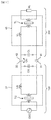
- FIG. 2 is an equivalent circuit diagram of the wireless power transmission system.
- the high frequency voltage generation circuit OSC of the power transmission device 100 generates a high frequency voltage of, for example, 100 kHz to several tens of MHz.
- the step-up transformer 37 using the step-up transformer TG and the inductor LG steps up the voltage generated by the high-frequency voltage generation circuit OSC and applies it between the power transmission device side passive electrode 31 and the power transmission device side active electrode 32.
- the capacitor CG is a parasitic capacitance generated between the power transmission device side passive electrode 31 and the power transmission device side active electrode 32.
- the inductor LG and the capacitor CG constitute a power transmission device side resonance circuit.
- a step-down circuit 45 including a step-down transformer TL and an inductor LL is connected between the power-receiving-device-side passive electrode 41 and the power-receiving-device-side active electrode 42 of the power receiving device 200.
- the step-down circuit 45 steps down the voltage received by the power receiving device side passive electrode 41 and the power receiving device side active electrode 42 and supplies power to the load circuit.
- the capacitor CL is a parasitic capacitance generated between the power receiving device side passive electrode 41 and the power receiving device side active electrode 42.
- the inductor LL and the capacitor CL constitute a power receiving device side resonance circuit.
- a load circuit RL is connected to the secondary side of the step-down transformer TL.
- the load circuit RL includes a DC / DC converter and a secondary battery.
- the capacitor Cm indicates the state of capacitive coupling between the power transmitting device side passive electrode 31, the power transmitting device side active electrode 32, and the power receiving device side passive electrode 41 and the power receiving device side active electrode.
- FIG. 3 is a block diagram illustrating specific configurations of the power transmission device 100 and the power reception device 200. Hereinafter, specific configurations of the power transmission device 100 and the power reception device 200 will be described.
- the power transmission device 100 includes a power transmission unit 30, a power supply unit 54, a control unit 52, a VDC, IDC detection circuit 53, and a VAC detection circuit 58.
- the power transmission unit 30 includes a power transmission device side passive electrode 31 and a power transmission device side active electrode 32.
- the power supply unit 54 is for supplying power to the power transmission unit 30 (the power transmission device side passive electrode 31 and the power transmission device side active electrode 32), and includes a DC power source 51, a power conversion unit 57, and a booster circuit 37.
- the DC power source 51 receives a DC voltage of DC 12V, generates a DC voltage of DC 5V, and supplies it to the controller 52. Further, the DC power supply 51 supplies the input DC voltage of 12 V to the VDC, IDC detection circuit 53 and the power converter 57.
- the VDC and IDC detection circuit 53 detects the voltage value VDC of the DC voltage supplied from the DC power supply 51 to the switching circuit 56 and the current value IDC of the current flowing through the switching circuit 56, and the VDC signal and DC current relating to the DC voltage value VDC. An IDC signal related to the value IDC is output.
- the power conversion unit 57 includes a switching circuit 56 and a drive control circuit 55.
- the power conversion unit 57 corresponds to the high-frequency voltage generation circuit OSC shown in FIG.
- the switching circuit 56 converts the DC voltage of DC 12V supplied from the DC power source 51 into an AC voltage by switching based on the drive signal from the drive control circuit 55, and outputs the AC voltage.
- FIG. 4 shows a specific configuration of the switching circuit 56.
- the switching circuit 56 includes a high-side switch element 56a and a low-side switch element 56b. A push-pull operation is performed by turning on and off these switch elements 56a and 56b, and the booster circuit 37 is driven alternately.
- the drive control circuit 55 drives the switch elements 56a and 56b of the switching circuit 56 in accordance with a signal output from the control unit 52.
- the booster circuit 37 boosts the AC voltage output from the switching circuit 56 and applies the boosted voltage between the power transmitting apparatus side passive electrode 31 and the power transmitting apparatus side active electrode 32.
- the step-up circuit 37 includes a step-up transformer TG in which a secondary winding is connected between the power transmission device side passive electrode 31 and the power transmission device side active electrode 32, and a primary winding is connected to the output of the switching circuit 56, and an inductor LG. (See FIG. 2).
- the voltage after boosting by the boosting circuit 37 is, for example, a voltage within a range of 100V to 10 kV. By applying this voltage between the power transmission device side passive electrode 31 and the power transmission device side active electrode 32, an electrostatic field is generated in the surrounding medium.
- the control unit 52 inputs the VDC signal and IDC signal from the VDC and IDC detection circuit 53, the VAC signal from the VAC detection circuit 58, and the like.
- the control unit 52 determines, for example, whether the voltage and current of DC 12V DC power output from the DC power supply 51 are within a predetermined range based on the VDC signal and the IDC signal.
- the control unit 52 controls ON and OFF of the switch elements 56a and 56b constituting the switching circuit 56 based on the IDC signal. Specifically, the control unit 52 obtains the ON / OFF duty ratio of the switch elements 56a and 56b constituting the switching circuit 56 based on the IDC signal, and generates the ON and OFF signals with the obtained duty ratio. And output to the drive control circuit 55. The drive control circuit 55 switches the switch elements 56a and 56b constituting the switching circuit 56 in accordance with the ON / OFF signal output from the control unit 52.
- the control unit 52 determines whether the voltage between the power transmission device side passive electrode 31 and the power transmission device side active electrode 32 is within a predetermined range. . It is judged whether or not it has risen abnormally.
- the power receiving device 200 includes a power receiving module 210 and a load circuit 220.
- the power reception module 210 includes a power reception unit 40, a step-down circuit 45, and a rectifier circuit 61.
- the power receiving unit 40 includes a power receiving device side passive electrode 41 and a power receiving device side active electrode 42.
- the power receiving device side passive electrode 41 and the power receiving device side active electrode 42 receive power from the power transmitting device side by capacitive coupling between the power transmitting device side passive electrode 31 and the power transmitting device side active electrode 32.
- the step-down circuit 45 steps down the voltage between the power receiving device side passive electrode 41 and the power receiving device side active electrode 42 and supplies the voltage to the load circuit 220 via the rectifier circuit 61.
- the step-down circuit 45 includes a step-down transformer TL in which a primary winding is connected between the power receiving device side passive electrode 41 and the power receiving device side active electrode 42 and a secondary winding is connected to the input of the load circuit 220, and an inductor LL. (See FIG. 2).
- the rectifier circuit 61 rectifies the AC power from the step-down circuit 45 and outputs it to the load circuit 220.
- the load circuit 220 includes a DC / DC converter 71 as a voltage stabilization circuit, and a secondary battery 72 connected to the secondary side of the DC / DC converter 71.
- the DC / DC converter 71 converts the DC voltage output from the rectifier circuit 61 into a DC voltage having a voltage value suitable for the secondary battery 72 and outputs the DC voltage.
- the secondary battery 72 is charged by the voltage output from the DC / DC converter 71.
- the secondary battery 72 has a characteristic in which the impedance increases as it approaches a fully charged state.
- the power transmission device 100 detects (estimates) the load impedance of the power reception device 200 using the physical quantity in the power transmission device 100, and according to the load state based on the detection result. Transmission power is controlled so that power can be appropriately supplied to the power receiving apparatus 100.
- the load impedance of the power receiving apparatus 200 is detected using the physical quantity in the power transmitting apparatus 100, it is not necessary to obtain information on the state of the load from the power receiving apparatus 200, and it is necessary to provide a communication circuit in the power transmitting apparatus and the power receiving apparatus. Disappear.
- the value IDC of the current flowing through the switching circuit 56 is used as a physical quantity in the power transmission device 100 used for detecting the load impedance of the power reception device 200.
- the reason why the current value IDC of the current flowing through the switching circuit 56 is used will be described with reference to FIG.
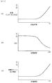
- FIG. 5A is a diagram showing the characteristics of the load impedance when the secondary battery 72 is charged in the load circuit 220.
- FIG. 5B shows the characteristics of the DC current value IDC when the secondary battery 72 is charged
- FIG. 5C shows the characteristics of the power receiving module output voltage when the secondary battery 72 is charged.
- the impedance (load impedance) of the load circuit 220 increases.
- the load impedance is a combination of the impedance of the DC / DC converter 71 and the impedance of the secondary battery 72.
- the secondary battery 72 has a characteristic that the impedance increases as the charging progresses.
- the DC current value IDC decreases as shown in FIG. 5B.
- a switching circuit is used for detecting the load impedance of the power receiving device 200.
- the current value IDC of the current flowing through 56 is used. Note that the output voltage (VRO) of the power reception module 210 increases as the secondary battery 72 is charged, as shown in FIG.
- the control unit 52 When the power receiving apparatus 200 is placed on the power transmitting apparatus 100, the control unit 52 performs initial setting for starting power transmission (S11). In the initial setting, a transmission frequency, a duty ratio, a transmission voltage, and the like are set.
- the control unit 52 inputs an IDC signal output from the VDC and IDC detection circuit 53 as a load impedance detection signal of the power receiving apparatus 200 (S12).
- the IDC signal is a signal indicating a current value of a direct current flowing through the switching circuit 56.
- the controller 52 determines whether or not the DC current value IDC indicated by the input IDC signal is equal to or less than a predetermined value (S13). If the direct current value IDC is equal to or less than the predetermined value, the control unit 52 ends the control according to this flowchart.
- the predetermined value is set to a value of the DC current value IDC that can be estimated that the secondary battery 72 is in a fully charged state. If the direct current value IDC is not less than or equal to the predetermined value, the control unit 52 sets a duty ratio corresponding to the direct current value IDC (S14). In the present embodiment, the duty ratio is set according to the DC current value IDC (that is, according to the load impedance).
- the duty ratio according to the state (load impedance) of the load circuit 220 of the power receiving device 200 can be set, and appropriate power is supplied to the power transmitting device 200 by controlling the output power using this duty ratio. It becomes possible to do. A specific method for setting the duty ratio will be described later.
- control unit 52 generates an ON / OFF signal having the set duty ratio, outputs it to the drive control circuit 55 (S15), and returns to step S12.
- the drive control circuit 55 performs ON / OFF control of the switch elements 56a and 56b of the switching circuit 56 based on the ON / OFF signal.
- the duty ratio for the switching circuit 56 is set according to the DC current value IDC (ie, load impedance).
- the duty ratio is set in advance so that the output voltage VRO of the rectifier circuit 61 of the power receiving device 200 does not exceed a certain voltage.
- setting of the duty ratio for the DC current value IDC will be described.
- the duty ratio for the DC current value IDC is defined by the setting table.
- the controller 52 refers to the setting table and determines the duty ratio for the switch elements 56a and 56b of the switching circuit 56 based on the direct current value IDC.
- FIG. 7 shows an example of a duty ratio setting table for the DC current value IDC.
- This setting table is stored in the storage unit 52A in the control unit 52.
- the setting table is for a case where the rated voltage of the DC / DC converter 71 is about 21 V.
- 14 stages of duty ratios are set in increments of 0.1 A of the DC current value IDC.
- the duty ratio is set so that the DC voltage value VRO output from the rectifier circuit 61 of the power receiving module 210 is substantially constant.
- FIG. 8 is a diagram showing the relationship of the duty ratio with respect to the DC current value IDC in the setting table of FIG.
- the duty ratio changes stepwise by 1% in increments of 0.1 A as the DC current value IDC changes.
- the duty ratio increases stepwise by 1% every time the DC current value IDC increases by 0.1 A. Note that during charging of the secondary battery 72, the DC current value IDC is the largest in the initial stage of charging, and decreases as the fully charged state is approached. Therefore, during charging of the secondary battery 72, the duty ratio is reduced as the fully charged state is approached.
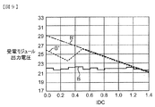
- FIG. 9 is a diagram showing the characteristics of the power receiving module output voltage with respect to the DC current value IDC in the setting table of FIG. With reference to the setting table of FIG. 7, by controlling the duty ratio based on the DC current value IDC, even if the DC current value IDC changes (decreases) as shown by the solid line B, the power receiving module output voltage is It is controlled to be almost constant at about 22V.
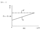
- FIG. 10 is a diagram showing the characteristics of the power receiving module output voltage in relation to the load impedance.
- the power reception module output voltage is approximately constant at approximately 22V.
- alternate long and short dash lines A ′, B ′, and C ′ indicate conventional characteristics.
- the duty ratio remains constant regardless of the DC current value IDC.
- the alternate long and short dash line B ′ in FIG. 9 when the DC current value IDC decreases, the power receiving module output voltage increases.
- the power receiving module output voltage increases. In this example, the power reception module output voltage is increased by about 8V from about 21V to about 29V.
- the output voltage of the power receiving module becomes higher overall and the fluctuation range becomes larger than in the case of controlling in the above-described 14 stages.
- the fluctuation range is reduced and the maximum value (when IDC is 0 A) is reduced as compared with the conventional case without the duty ratio control indicated by the broken line B ′.
- the output voltage of the power receiving module increases up to about 200 ⁇ and increases up to about 26V by about 5V.
- the duty ratio is changed to 37%.
- FIG. 11 is a diagram illustrating a duty ratio setting table T for the IDC in another example.
- the duty ratio is changed continuously (in a stepless manner) in proportion to the direct current value IDC.
- the duty ratio corresponding to the IDC can be obtained by calculation using a function or the like instead of the setting table.
- FIG. 12 is a diagram illustrating characteristics of the power reception module output voltage with respect to the IDC.
- the duty ratio is set so that the DC voltage output from the rectifier circuit 61 of the power receiving module 210 is substantially constant as indicated by the solid line E in FIG.
- the dashed-dotted line D 'of FIG. 11 and the dashed-dotted line E' of FIG. 12 show the conventional example mentioned above.
- the power transmission device 100 is a power transmission device 100 that wirelessly transmits power to the power reception device 200 that rectifies the voltage received by the power reception unit 40 by the rectifier circuit 61 and supplies the voltage to the load circuit 220.
- the power transmission device 100 is capacitively coupled or electromagnetically coupled with the power reception unit 40 of the power reception device 200, generates power to be transmitted to the power reception device 200, and a power transmission unit 30 that transmits power to the power reception unit 40.
- the load impedance detection unit that detects the load impedance of the power receiving device 200 based on the electrical signal detected in the power transmission device 100, and the load impedance detection unit
- the control unit 52 controls the power generated by the power supply unit 54 so that the output voltage of the rectifier circuit 61 of the power receiving device 200 is equal to or lower than a predetermined voltage.
- the power transmission device 100 detects (estimates) the load impedance in the power receiving device 200 using the DC current value IDC (electric signal) detected in the power transmission device 100, and based on the detection result, the power receiving device 200.
- the power supplied to the power receiving apparatus 200 is controlled so that the output voltage of the rectifier circuit 61 is equal to or lower than a predetermined voltage. Accordingly, the output voltage can be controlled to be constant regardless of the coupling state of the power reception device and the power transmission device or the load state. Therefore, appropriate power corresponding to the load state can be supplied to the power receiving apparatus 200 without providing a communication circuit in the power transmitting apparatus 100 and the power receiving apparatus 200.
- the power receiving device 200 is, for example, a smartphone or a mobile phone, and is required to be reduced in cost or reduced in size.
- a communication circuit with the power transmitting device 100, a load state detection sensor, and the like Parts are not required. Therefore, the substrate of the power receiving module 210 and the power receiving device 200 can be reduced in size and cost.
- the power supply unit 54 converts the DC power supplied from the DC power supply 51 into AC power to the power transmission unit 30 by converting the DC power supplied from the DC power supply 51 into the AC power.
- the load impedance detection unit detects the current value IDC of the DC current flowing from the DC power supply 51 to the power conversion unit 57.
- the control unit 52 controls the power conversion mode in the power conversion unit 57 so that power suitable for the load circuit 220 of the power receiving apparatus 200 is supplied based on the DC current value IDC detected by the load impedance detection unit. .
- the power in the power conversion unit 57 is supplied so that power suitable for the load circuit 220 of the power receiving device 200 is supplied based on the current value IDC of the DC power supplied from the DC power supply 51 to the power conversion unit 57.
- the conversion mode is controlled.
- the value IDC of the DC current supplied from the DC power supply 51 to the power conversion unit 57 favorably reflects the change in the impedance of the secondary battery 72 as described above. Therefore, even when the state of the load circuit 220 of the power receiving device 200 changes, it is possible to supply power suitable for the load circuit 220.
- DC power is supplied to the load circuit 220 of the power reception device 200.
- the power conversion unit 57 generates AC power by periodically turning ON / OFF the DC voltage supplied from the DC power supply 51.
- the controller 52 controls the ON / OFF duty ratio in the power converter 57 based on the DC current value IDC detected by the load impedance detector.
- the ON / OFF duty ratio in the power conversion unit 57 is controlled based on the DC current value IDC detected by the load impedance detection unit. Therefore, an overvoltage is prevented from being applied to the load circuit 220. Further, the control can be easily and surely performed by the duty ratio control.
- the duty ratio for the detected current value IDC is determined based on a predetermined relationship between the DC current value IDC and the duty ratio.
- This configuration makes it possible to control the duty ratio with an easy and simple configuration.
- the load circuit 220 includes a DC / DC converter 71 and a secondary battery 72 connected to the secondary side of the DC / DC converter 71.
- the voltage applied to the DC / DC converter 71 and the secondary battery 72 can be a constant voltage.
- the power reception unit 40 includes a power reception device side active electrode 42 (power reception side first electrode) and a power reception device side passive electrode 41 (power reception side second electrode). Are capacitively coupled to the power receiving device side active electrode 32 (power receiving side first electrode) and the power receiving device side passive electrode 41 (power receiving side second electrode). Power transmission device side passive electrode 31 (power transmission side second electrode).
- the voltage of the power transmission device side active electrode 32 (power transmission side first electrode) is larger than the voltage of the power transmission device side passive electrode 31 (power transmission side second electrode).
- the voltage of the power transmission device side active electrode 32 (power transmission side first electrode) and the power reception device side active electrode 42 (power reception side first electrode) can be set to a high voltage. Therefore, power transmission efficiency can be increased.
- the secondary winding is connected between the power transmission device side active electrode 32 (power transmission side first electrode) and the power transmission device side passive electrode 31 (power transmission side second electrode), It further includes a step-up transformer TG having a primary winding connected to the output of the power conversion unit 57.
- the voltage of the power transmission device side active electrode 32 (power transmission side first electrode) and the power reception device side active electrode 42 (power reception side first electrode) can be made higher.
- a large amount of power can be transmitted at a low current, so that a power loss due to a conductor loss in the power transmission path can be reduced. Therefore, the power transmission efficiency can be further increased.
- a power transmission system including the power receiving device 200 including the power receiving unit 40 and the load circuit 220 and the above-described power transmitting device 100 is provided.
- the same effect as that described in the power transmission device 100 can be obtained.
- a power transmission method is provided in the power transmission device 100 that wirelessly transmits power to the power reception device 200 that rectifies the voltage received by the power reception unit 40 and supplies the voltage to the load circuit 61.
- the power transmission method generates power to be transmitted to the power receiving device 200, supplies the power to the power transmitting unit 30, and detects a load impedance of the power receiving device 200 based on an electrical signal detected in the power transmitting device 100. And controlling the power supplied to the power transmission unit 100 so that the output voltage of the rectifier circuit 61 of the power receiving device 200 is equal to or lower than a predetermined voltage based on the detection result of the load impedance.
- the same effect as that described in the power transmission device 100 can be obtained.
- the load impedance on the power receiving device side is detected by the VDC and IDC detection circuit 53, but may be detected by the VAC detection circuit 58.
- the AC voltage value VAC detected by the VAC detection circuit 58 indicates a voltage corresponding to the impedance of the secondary battery 72, like the DC current value IDC detected by the IDC detection unit 53. Therefore, the same effect as in the case of the IDC detection unit 53 can be obtained.
- the duty ratio of each switching element of the switching circuit 56 is controlled according to the load impedance (PWM control).
- PWM control the magnitude of the DC voltage VDC input to the switching circuit 56 may be controlled according to the load impedance (PAM control).
- the present invention can be applied to cases other than the secondary battery 72. Applicable. For example, it is possible to supply a constant voltage even to an electronic device or the like in which the impedance of the load changes according to the operating state even when the impedance of the load changes. Therefore, it is possible to stabilize the operation of the electronic device regardless of fluctuations in load impedance.
- the load circuit 220 has the DC / DC converter 71 as the voltage stabilizing circuit and the secondary battery 72 as the secondary load of the DC / DC converter 71.
- the load circuit 220 ′ includes a voltage regulator 81 as a voltage stabilization circuit, a secondary battery 82 as a secondary load of the voltage regulator 81, and the secondary battery 82 or voltage regulator 81.
- the present invention can also be applied to the case where the device 84 that operates by the supplied power and the power control circuit 83 that controls the supply of power to the device 84 are provided.
- the secondary battery 82 has a built-in charge control circuit. In this example as well, a constant voltage can be supplied even when the impedance of the load changes. Therefore, the operation of the electronic apparatus including the device 84 and the like can be stabilized regardless of the change in load impedance.
- a charge control circuit 85 may be provided separately between the voltage regulator 81 and the secondary battery 82 ′ as in a load circuit 220 ′′ shown in FIG.
- the present invention can also be applied to a case where the voltage stabilizing circuit of the load circuit of the power receiving device includes both a DC / DC converter and a voltage regulator.
- Power Transmission Unit 31 Power Transmission Device Side Passive Electrode (Power Transmission Side Second Electrode) 32 Power transmission device side active electrode (power transmission side first electrode) 37 Booster circuit 40 Power receiving unit 41 Power receiving device side passive electrode (power receiving side second electrode) 42 Power receiving device side active electrode (power receiving side first electrode) 45 Step-down circuit 51 DC power supply 52 Control unit 52A Storage unit 53 VDC, IDC detection circuit 54 Power supply unit 55 Drive control circuit 56 Switching circuit 57 Power conversion unit 58 VAC detection circuit 61 Rectifier circuit 71 DC / DC converters 72, 82, 82 'Secondary battery 81 Voltage regulator 83 Power control circuit 84 Device 85 Charging control circuit 100 Power transmission device 200 Power reception device 210 Power reception module 220, 220', 220 "Load circuit CG, CL ... Capacitor LG, LL ... Inductor OSC ... High frequency voltage generation Circuit RL ... Load circuit TG ... Step-up transformer TL ... Step-down transformer
Landscapes
- Engineering & Computer Science (AREA)
- Power Engineering (AREA)
- Computer Networks & Wireless Communication (AREA)
- Charge And Discharge Circuits For Batteries Or The Like (AREA)
Priority Applications (3)
| Application Number | Priority Date | Filing Date | Title |
|---|---|---|---|
| CN201390000352.6U CN204290504U (zh) | 2012-03-26 | 2013-02-26 | 电力传输系统以及用于该电力传输系统的送电装置 |
| JP2014507548A JP5867592B2 (ja) | 2012-03-26 | 2013-02-26 | 電力伝送システム及びそれに用いる送電装置 |
| US14/481,220 US9948144B2 (en) | 2012-03-26 | 2014-09-09 | Power transmission system and power transmission device used for power transmission system |
Applications Claiming Priority (2)
| Application Number | Priority Date | Filing Date | Title |
|---|---|---|---|
| JP2012-070072 | 2012-03-26 | ||
| JP2012070072 | 2012-03-26 |
Related Child Applications (1)
| Application Number | Title | Priority Date | Filing Date |
|---|---|---|---|
| US14/481,220 Continuation US9948144B2 (en) | 2012-03-26 | 2014-09-09 | Power transmission system and power transmission device used for power transmission system |
Publications (1)
| Publication Number | Publication Date |
|---|---|
| WO2013146017A1 true WO2013146017A1 (fr) | 2013-10-03 |
Family
ID=49259294
Family Applications (1)
| Application Number | Title | Priority Date | Filing Date |
|---|---|---|---|
| PCT/JP2013/054978 Ceased WO2013146017A1 (fr) | 2012-03-26 | 2013-02-26 | Système de transmission électrique et appareil de transmission électrique utilisé dans celui-ci |
Country Status (4)
| Country | Link |
|---|---|
| US (1) | US9948144B2 (fr) |
| JP (1) | JP5867592B2 (fr) |
| CN (1) | CN204290504U (fr) |
| WO (1) | WO2013146017A1 (fr) |
Cited By (8)
| Publication number | Priority date | Publication date | Assignee | Title |
|---|---|---|---|---|
| WO2015125148A1 (fr) * | 2014-02-22 | 2015-08-27 | Humavox Ltd. | Dispositif de charge sans fil et procédés d'utilisation |
| JP2015156741A (ja) * | 2014-02-20 | 2015-08-27 | 株式会社村田製作所 | 電力伝送システム、受電装置及び送電装置 |
| CN105379067A (zh) * | 2014-06-06 | 2016-03-02 | 株式会社村田制作所 | 电力传输系统 |
| CN111651028A (zh) * | 2015-07-31 | 2020-09-11 | 电力集成瑞士有限公司 | 信号发射电路和包括该信号发射电路的装置 |
| WO2021049346A1 (fr) * | 2019-09-09 | 2021-03-18 | パナソニックIpマネジメント株式会社 | Dispositif de transmission d'électricité et système de transfert d'électricité sans fil |
| WO2023076174A1 (fr) * | 2021-10-26 | 2023-05-04 | Milwaukee Electric Tool Corporation | Charge sans fil de blocs-batteries d'outil électrique |
| JP2024128044A (ja) * | 2020-10-23 | 2024-09-20 | ニチコン株式会社 | 磁界共振電源装置 |
| US12512702B2 (en) | 2020-09-22 | 2025-12-30 | Milwaukee Electric Tool Corporation | Wireless charging pad for power tool battery packs |
Families Citing this family (21)
| Publication number | Priority date | Publication date | Assignee | Title |
|---|---|---|---|---|
| KR101848097B1 (ko) | 2012-01-11 | 2018-04-11 | 삼성전자주식회사 | 공진 방식 무선 전력 송신 장치용 과전압 보호 장치 및 그 제어 방법 |
| KR101943082B1 (ko) * | 2014-01-23 | 2019-04-18 | 한국전자통신연구원 | 무선 전력 송신 장치, 무선 전력 수신 장치, 및 무선 전력 전송 시스템 |
| US20170310117A1 (en) * | 2014-04-09 | 2017-10-26 | Prasanna Sharadchandra Nirantare | Systems And Methods For Closed Loop Control For Wireless Power Transfer |
| JP2016029785A (ja) * | 2014-07-18 | 2016-03-03 | 株式会社東芝 | 通信システム |
| JP2016139985A (ja) * | 2015-01-28 | 2016-08-04 | 株式会社東芝 | 送信回路、受信回路及び通信システム |
| MX360571B (es) * | 2015-06-01 | 2018-11-08 | Guangdong Oppo Mobile Telecommunications Corp Ltd | Circuito de carga y terminal móvil. |
| CN104979914B (zh) * | 2015-06-11 | 2018-05-25 | 昆明理工大学 | 一种电场耦合式无线电能传输系统 |
| US10498220B2 (en) * | 2015-09-17 | 2019-12-03 | Ihi Corporation | Power transmitter and wireless power transfer system |
| CN106560979B (zh) * | 2015-10-02 | 2021-03-30 | 松下知识产权经营株式会社 | 无线电力传输系统 |
| US10873219B2 (en) * | 2016-09-30 | 2020-12-22 | Fuji Corporation | Contactless power supply device |
| CN108539871B (zh) * | 2017-03-02 | 2021-10-08 | 泰达电子股份有限公司 | 无线电能传输装置 |
| TWI631791B (zh) * | 2017-03-22 | 2018-08-01 | Anpec Electronics Corporation | 切換式充電電路 |
| CN207303993U (zh) * | 2017-10-24 | 2018-05-01 | 佛山市顺德区美的电热电器制造有限公司 | 过流过压保护电路、电磁感应式无线供电系统及烹饪器具 |
| CN107623387A (zh) * | 2017-11-06 | 2018-01-23 | 王珏 | 一种无线供电系统 |
| CN108011453B (zh) * | 2017-12-15 | 2019-07-26 | 清华大学深圳研究生院 | 一种无线能量传输控制方法 |
| US11462946B2 (en) * | 2018-09-05 | 2022-10-04 | Mitsubishi Electric Corporation | Non-contact power supply system and power transmission device |
| EP3900155B1 (fr) | 2018-12-21 | 2025-04-16 | Solace Power Inc. | Système de transfert sans fil de puissance de champ électrique, émetteur et récepteur pour ce dernier et procédé de transfert sans fil de puissance |
| WO2020124243A1 (fr) * | 2018-12-21 | 2020-06-25 | Solace Power Inc. | Système de transfert d'énergie de champ électrique/magnétique sans fil, émetteur et récepteur |
| US10797593B1 (en) | 2019-04-23 | 2020-10-06 | Analog Devices International Unlimited Company | Kappa switching DC-DC converter with continuous input and output currents |
| JP7418613B2 (ja) * | 2020-12-14 | 2024-01-19 | 三菱電機株式会社 | 送電装置及び非接触給電システム |
| CN115514071B (zh) * | 2022-09-26 | 2024-08-30 | 深圳易能电科技有限公司 | 一种低功耗的充电电路以及应用该充电电路的充电装置 |
Citations (5)
| Publication number | Priority date | Publication date | Assignee | Title |
|---|---|---|---|---|
| JP2004248365A (ja) * | 2003-02-12 | 2004-09-02 | Yazaki Corp | 無接点電力伝送装置、無接点電力伝送方法 |
| JP2009296857A (ja) * | 2008-06-09 | 2009-12-17 | Sony Corp | 伝送システム、給電装置、受電装置、及び伝送方法 |
| JP2010183810A (ja) * | 2009-02-09 | 2010-08-19 | Toyota Industries Corp | 非接触電力伝送装置 |
| JP2010233442A (ja) * | 2009-03-06 | 2010-10-14 | Nissan Motor Co Ltd | 非接触電力供給装置及び方法 |
| JP2012039800A (ja) * | 2010-08-10 | 2012-02-23 | Murata Mfg Co Ltd | 電力伝送システム |
Family Cites Families (11)
| Publication number | Priority date | Publication date | Assignee | Title |
|---|---|---|---|---|
| GB2119102B (en) * | 1982-04-01 | 1985-09-04 | Victor Company Of Japan | Load impedance detector for audio power amplifiers |
| JP3344593B2 (ja) | 1992-10-13 | 2002-11-11 | 株式会社ソニー木原研究所 | 無線式電力供給装置 |
| US5631611A (en) * | 1996-06-18 | 1997-05-20 | Nautel Limited | Automatic matching and tuning network |
| WO2007058910A2 (fr) * | 2005-11-10 | 2007-05-24 | Kathleen Lowe Melde | Appareil et procede de selection de composants pour circuit d'equilibre des impedances reconfigurable |
| JP2009273327A (ja) * | 2008-05-10 | 2009-11-19 | Sanyo Electric Co Ltd | 電池内蔵機器と充電台 |
| US9561730B2 (en) * | 2010-04-08 | 2017-02-07 | Qualcomm Incorporated | Wireless power transmission in electric vehicles |
| JP2011223739A (ja) * | 2010-04-09 | 2011-11-04 | Sony Corp | 給電装置、受電装置、およびワイヤレス給電システム |
| EP2579426B1 (fr) | 2010-05-28 | 2019-03-27 | Murata Manufacturing Co., Ltd. | Système de transmission d'énergie |
| US8634216B2 (en) * | 2010-07-08 | 2014-01-21 | Solarbridge Technologies, Inc. | Communication within a power inverter using transformer voltage frequency |
| US8604873B2 (en) * | 2010-12-05 | 2013-12-10 | Rf Micro Devices (Cayman Islands), Ltd. | Ground partitioned power amplifier for stable operation |
| US9071284B2 (en) * | 2011-10-21 | 2015-06-30 | Qualcomm Incorporated | Load impedance detection for static or dynamic adjustment of passive loads |
-
2013
- 2013-02-26 WO PCT/JP2013/054978 patent/WO2013146017A1/fr not_active Ceased
- 2013-02-26 JP JP2014507548A patent/JP5867592B2/ja active Active
- 2013-02-26 CN CN201390000352.6U patent/CN204290504U/zh not_active Expired - Lifetime
-
2014
- 2014-09-09 US US14/481,220 patent/US9948144B2/en active Active
Patent Citations (5)
| Publication number | Priority date | Publication date | Assignee | Title |
|---|---|---|---|---|
| JP2004248365A (ja) * | 2003-02-12 | 2004-09-02 | Yazaki Corp | 無接点電力伝送装置、無接点電力伝送方法 |
| JP2009296857A (ja) * | 2008-06-09 | 2009-12-17 | Sony Corp | 伝送システム、給電装置、受電装置、及び伝送方法 |
| JP2010183810A (ja) * | 2009-02-09 | 2010-08-19 | Toyota Industries Corp | 非接触電力伝送装置 |
| JP2010233442A (ja) * | 2009-03-06 | 2010-10-14 | Nissan Motor Co Ltd | 非接触電力供給装置及び方法 |
| JP2012039800A (ja) * | 2010-08-10 | 2012-02-23 | Murata Mfg Co Ltd | 電力伝送システム |
Cited By (13)
| Publication number | Priority date | Publication date | Assignee | Title |
|---|---|---|---|---|
| JP2015156741A (ja) * | 2014-02-20 | 2015-08-27 | 株式会社村田製作所 | 電力伝送システム、受電装置及び送電装置 |
| WO2015125148A1 (fr) * | 2014-02-22 | 2015-08-27 | Humavox Ltd. | Dispositif de charge sans fil et procédés d'utilisation |
| CN106134031A (zh) * | 2014-02-22 | 2016-11-16 | 胡玛沃克斯公司 | 无线充电设备以及使用方法 |
| JP2017509297A (ja) * | 2014-02-22 | 2017-03-30 | ヒューマヴォックス リミテッド | 無線充電デバイスおよびその使用方法 |
| CN105379067A (zh) * | 2014-06-06 | 2016-03-02 | 株式会社村田制作所 | 电力传输系统 |
| CN105379067B (zh) * | 2014-06-06 | 2018-04-03 | 株式会社村田制作所 | 电力传输系统 |
| CN111651028A (zh) * | 2015-07-31 | 2020-09-11 | 电力集成瑞士有限公司 | 信号发射电路和包括该信号发射电路的装置 |
| CN111651028B (zh) * | 2015-07-31 | 2023-07-07 | 电力集成瑞士有限公司 | 信号发射电路和包括该信号发射电路的装置 |
| WO2021049346A1 (fr) * | 2019-09-09 | 2021-03-18 | パナソニックIpマネジメント株式会社 | Dispositif de transmission d'électricité et système de transfert d'électricité sans fil |
| US12512702B2 (en) | 2020-09-22 | 2025-12-30 | Milwaukee Electric Tool Corporation | Wireless charging pad for power tool battery packs |
| JP2024128044A (ja) * | 2020-10-23 | 2024-09-20 | ニチコン株式会社 | 磁界共振電源装置 |
| JP7687802B2 (ja) | 2020-10-23 | 2025-06-03 | ニチコン株式会社 | 磁界共振電源装置 |
| WO2023076174A1 (fr) * | 2021-10-26 | 2023-05-04 | Milwaukee Electric Tool Corporation | Charge sans fil de blocs-batteries d'outil électrique |
Also Published As
| Publication number | Publication date |
|---|---|
| US9948144B2 (en) | 2018-04-17 |
| CN204290504U (zh) | 2015-04-22 |
| JPWO2013146017A1 (ja) | 2015-12-10 |
| JP5867592B2 (ja) | 2016-02-24 |
| US20140375251A1 (en) | 2014-12-25 |
Similar Documents
| Publication | Publication Date | Title |
|---|---|---|
| JP5867592B2 (ja) | 電力伝送システム及びそれに用いる送電装置 | |
| JP6168193B2 (ja) | 電子装置 | |
| CN103199633B (zh) | 照明用无线供电系统和照明设备 | |
| US9825485B2 (en) | Wireless power transmitter and wireless power receiver | |
| KR101818773B1 (ko) | 공진 방식 무선 충전 시스템용 수신 전력 변환 장치 | |
| US8987941B2 (en) | Power transmission system | |
| JP5550785B2 (ja) | 非接触型の誘導電力伝送システムの回路 | |
| EP4024656B1 (fr) | Appareil et système à charger, procédé de charge sans fil et support de stockage | |
| KR20180098608A (ko) | 단말을 위한 충전 시스템, 충전 방법 및 전원 어댑터 | |
| JP5696681B2 (ja) | 電力伝送システム並びにその送電装置及び受電装置 | |
| US10784707B2 (en) | Inductive power transfer system | |
| JP2013078171A (ja) | 受電装置及び非接触給電システム | |
| JP2016537951A (ja) | 無線電力送受信方法及び装置 | |
| US20130334893A1 (en) | Power transmission system and power transmitting apparatus | |
| JP2010104159A (ja) | 受電端末、および無接点電力伝送システム | |
| KR102773408B1 (ko) | 무선 전력 전송 전력 제어 기술 | |
| JP2014204604A (ja) | 電子機器および給電システム | |
| WO2015033860A1 (fr) | Dispositif de transmission de puissance, système de transmission de puissance sans fil et procédé de discrimination de transmission de puissance | |
| US9787104B2 (en) | Power transmission system | |
| WO2015019908A1 (fr) | Système de transmission d'énergie sans fil | |
| JP6685016B2 (ja) | 非接触給電装置、プログラム、非接触給電装置の制御方法、及び非接触電力伝送システム | |
| JP2008104319A (ja) | 非接触電力伝送装置 | |
| KR101405806B1 (ko) | 전력 공급 장치, 무선전력 송신장치 및 전력 공급 방법 | |
| JPWO2016084524A1 (ja) | 送電装置及び電力伝送システム |
Legal Events
| Date | Code | Title | Description |
|---|---|---|---|
| WWE | Wipo information: entry into national phase |
Ref document number: 201390000352.6 Country of ref document: CN |
|
| 121 | Ep: the epo has been informed by wipo that ep was designated in this application |
Ref document number: 13768790 Country of ref document: EP Kind code of ref document: A1 |
|
| ENP | Entry into the national phase |
Ref document number: 2014507548 Country of ref document: JP Kind code of ref document: A |
|
| NENP | Non-entry into the national phase |
Ref country code: DE |
|
| 122 | Ep: pct application non-entry in european phase |
Ref document number: 13768790 Country of ref document: EP Kind code of ref document: A1 |