WO2013146051A1 - Dispositif de filtrage, appareil formant objectif et appareil de prise d'image - Google Patents
Dispositif de filtrage, appareil formant objectif et appareil de prise d'image Download PDFInfo
- Publication number
- WO2013146051A1 WO2013146051A1 PCT/JP2013/055244 JP2013055244W WO2013146051A1 WO 2013146051 A1 WO2013146051 A1 WO 2013146051A1 JP 2013055244 W JP2013055244 W JP 2013055244W WO 2013146051 A1 WO2013146051 A1 WO 2013146051A1
- Authority
- WO
- WIPO (PCT)
- Prior art keywords
- filter
- filter device
- filters
- optical density
- optical
- Prior art date
- Legal status (The legal status is an assumption and is not a legal conclusion. Google has not performed a legal analysis and makes no representation as to the accuracy of the status listed.)
- Ceased
Links
Images




Classifications
-
- G—PHYSICS
- G03—PHOTOGRAPHY; CINEMATOGRAPHY; ANALOGOUS TECHNIQUES USING WAVES OTHER THAN OPTICAL WAVES; ELECTROGRAPHY; HOLOGRAPHY
- G03B—APPARATUS OR ARRANGEMENTS FOR TAKING PHOTOGRAPHS OR FOR PROJECTING OR VIEWING THEM; APPARATUS OR ARRANGEMENTS EMPLOYING ANALOGOUS TECHNIQUES USING WAVES OTHER THAN OPTICAL WAVES; ACCESSORIES THEREFOR
- G03B11/00—Filters or other obturators specially adapted for photographic purposes
-
- H—ELECTRICITY
- H04—ELECTRIC COMMUNICATION TECHNIQUE
- H04N—PICTORIAL COMMUNICATION, e.g. TELEVISION
- H04N23/00—Cameras or camera modules comprising electronic image sensors; Control thereof
- H04N23/70—Circuitry for compensating brightness variation in the scene
- H04N23/75—Circuitry for compensating brightness variation in the scene by influencing optical camera components
-
- H—ELECTRICITY
- H04—ELECTRIC COMMUNICATION TECHNIQUE
- H04N—PICTORIAL COMMUNICATION, e.g. TELEVISION
- H04N23/00—Cameras or camera modules comprising electronic image sensors; Control thereof
- H04N23/50—Constructional details
- H04N23/55—Optical parts specially adapted for electronic image sensors; Mounting thereof
Definitions
- the present invention relates to a filter device that allows a light beam to pass therethrough, and a lens device and an imaging device that include the filter device.
- a filter device configured to change the transmittance of a light beam to be transmitted using two ND (Neutral Density) filters is known (for example, see Patent Document 1).
- the filter device described in Patent Document 1 includes two ND filters that are rotatably supported around the same rotation axis, and each ND filter has an optical density that continuously changes around the rotation axis. It is formed as follows. The two ND filters are arranged so that the change gradient of the optical density is opposite to each other around the rotation axis.
- the total optical density of the region through which the light beam passes is the sum of the optical densities of the two ND filters, and according to the above arrangement of the two ND filters, it is uniform over the entire region through which the light beam passes. Then, by rotating the two ND filters in opposite directions around the rotation axis, the total optical density of the light beam passage region continuously increases and decreases while maintaining uniformity in the entire region.
- an ND filter is used in which a predetermined gradation pattern is printed on a glass substrate using an ink containing a black pigment such as carbon black.
- the ND filter whose optical density is continuously changed is obtained by exposing and developing the emulsion layer of a silver halide photographic photosensitive film comprising a film base and an emulsion layer in a predetermined gradation pattern.
- a silver halide photographic photosensitive film comprising a film base and an emulsion layer in a predetermined gradation pattern.
- the glass substrate is given an ultraviolet cut function so that the glass substrate faces the upstream side in the traveling direction of the luminous flux and the functional film faces the downstream side.
- an imaging device in which a filter is arranged see Patent Document 3).
- the black ink forming the optical film in the ND filter described in Patent Document 1 and the developed silver forming the optical film in the ND filter described in Patent Document 2 both absorb light. Although it adjusts the transmittance, it also absorbs ultraviolet rays, which may cause deterioration such as discoloration.
- the light beam incident on the filter device is attenuated by an ND filter (hereinafter referred to as a first ND filter) located upstream in the traveling direction, and is attenuated to an ND filter (hereinafter referred to as a second ND filter) located downstream. Enters the light beam attenuated through the first ND filter. For this reason, the degradation of the ND filter due to ultraviolet rays proceeds relatively quickly in the first ND filter.
- the upstream side in the traveling direction of the light beam means the subject side
- the downstream side means the image side.
- the lifetime of the filter device is limited to the lifetime of the first ND filter whose deterioration progresses relatively quickly.
- each of the two ND filters is arranged so that the glass substrate faces the upstream side and the optical film faces the downstream side, it is possible to suppress deterioration of the individual ND filters. it can. However, even if the deterioration of each ND filter can be suppressed, it is not possible to suppress a difference in deterioration between the two ND filters, and eventually the life of the filter device can be extended. Absent.
- the present invention has been made in view of the above-described circumstances, and an object thereof is to extend the life of the filter device.
- a filter device that allows a light beam to pass therethrough, and includes two ND filters arranged so as to intersect with the light beam, and each ND filter has an optical density distribution that changes linearly with a predetermined inclination in one direction.
- the two ND filters are overlapped so that the gradients of change in the optical density in the passage region through which the light beam passes are opposite to each other, the increase and decrease in the optical density in the passage region of the light beam tend to be the same, and On the central axis, the optical density of the first ND filter located upstream in the traveling direction of the luminous flux is moved in the direction of change of each optical density so that the optical density of the second ND filter located downstream is smaller.
- the degradation of the ND filter due to ultraviolet rays is not concentrated on the first ND filter located upstream in the traveling direction of the light beam, but is distributed to the first and second ND filters, thereby extending the lifetime of the filter device. can do.
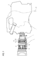
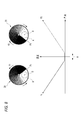
- FIG. 1 is a side view schematically illustrating a configuration of an example of a lens device and an imaging device to which the lens device is mounted for explaining an embodiment of the present invention. It is a principal part functional block diagram of the imaging device of FIG. It is a side view which shows typically the structure of an example of the ND filter contained in the filter apparatus incorporated in the lens apparatus of FIG. It is a front view which shows typically an example of the optical density distribution of the ND filter shown in FIG. It is a perspective view which shows typically the structure of the filter apparatus incorporated in the lens apparatus of FIG.
- FIG. 6 is a front view showing a configuration of a drive unit that rotationally drives an ND filter in the filter device of FIG. 5.
- It is a rear view of the drive part of FIG. 6 is a graph showing the relationship between the angle around the rotation axis of the ND filter and the optical density in the filter device of FIG. 5.
- 6 is a graph showing the relationship between the angle around the rotation axis of the ND filter and the optical density in the filter device of FIG. 5.
- It is a graph which shows the relationship between the angle around the rotating shaft of ND filter, and an optical density as a reference example.
- It is a side view which shows typically the structure of the modification of the filter apparatus of FIG.
- It is a perspective view which shows typically the structure of the other example of the filter apparatus for describing embodiment of this invention.
- It is a side view which shows typically the structure of the modification of the filter apparatus of FIG.
- FIG. 1 shows a configuration of an example of a lens device and an imaging device equipped with the lens device for explaining an embodiment of the present invention.
- the imaging apparatus shown in FIG. 1 includes an imaging apparatus main body 1 and a lens device 2 attached to the imaging apparatus main body 1.
- the lens device 2 includes a cylindrical barrel 10 such as a cylindrical shape.
- the lens barrel 10 includes a photographing lens such as a zoom lens and a focus lens, and a diaphragm device that adjusts the amount of light passing through the aperture through which the light beam passes. Further, in the lens device 2, a filter device that allows a light beam to pass through with a variable transmittance is incorporated in the lens barrel 10.
- the lens device 2 includes a focus ring 11 as an operating tool for adjusting the focus, a zoom ring 12 as an operating tool for adjusting the zoom, an iris ring 13 as an operating tool for adjusting the aperture of the aperture device, and a filter device.
- a filtering 14 as an operation tool for adjusting the transmittance is provided to be rotatable around the outer periphery of the lens barrel 10.
- the zoom ring 12 When the photographer H rotates the focus ring 11, the zoom ring 12, the iris ring 13, and the filtering 14, the focus adjustment, the zoom adjustment, the aperture opening adjustment, and the filter device transmittance adjustment are performed. Is done.
- FIG. 2 shows a main functional block of the imaging apparatus of FIG.
- a broken line circle X in FIG. 2 indicates an operation portion of the lens apparatus 2 in which the filtering 14 is provided.
- the lens device 2 includes the taking lenses 20 and 21 such as the zoom lens and the focus lens, the diaphragm device 22 and the filter device 23.
- the filter device 23 includes two ND filters 30 and 31 rotatably supported on the same rotation axis parallel to the central axis of the light beam passing through the photographing lenses 20 and 21 and the diaphragm device 22, and these ND filters 30. , 31 including a motor 32 that rotationally drives the drive unit.
- the lens barrel 10 of the lens device 2 is provided with a potentiometer 33 that engages with the filtering 14 and detects the operation amount (rotation angle) of the filtering 14.
- the CPU 34 of the lens device 2 detects the filtering 14 detected by the potentiometer 33.
- the motor 32 is controlled in accordance with the rotation angle.
- the driving unit rotates the two ND filters 30 and 31 under the control of the motor 32 by the CPU 34. Thereby, the transmittance of the filter device 23 is adjusted to the transmittance according to the rotation angle of the filtering 14.
- the imaging device main body 1 incorporates an imaging element module 35.
- the image sensor module 35 separates incident light that has passed through the lens device 2 into red (R), green (G), and blue (B) three-color light, and red light (R light) separated by the prism 36.
- An image sensor 37R for detecting, an image sensor 37G for detecting green light (G light) separated by the prism 36, and an image sensor 37B for detecting blue light (B light) separated by the prism 36 are configured. Yes.
- the detection signals of the image pickup devices 37R, 37G, and 37B are output as, for example, television signals after appropriate image processing such as white ballast correction in the image processing unit 38.
- the adjustment of the transmittance of the filter device 23 can be switched between manual adjustment by the photographer and automatic adjustment.
- the CPU 39 of the imaging device main body 1 calculates an appropriate exposure based on the luminance information of the captured image captured by the imaging element module 35, and uses this for the lens device 2. It transmits to CPU34.
- the CPU 34 of the lens device 2 calculates the transmittance in the filter device 23 that obtains appropriate exposure in relation to the opening amount of the aperture device 22 so that the calculated transmittance can be obtained. To control.
- FIG. 3 shows an example of the configuration of the ND filters 30 and 31.
- the ND filters 30 and 31 are absorption ND filters.
- the ND filters described in Patent Document 1 and Patent Document 2 can be used, but in this example, a transparent substrate formed in a disk shape. 40 and an optical film 41 formed directly on the substrate 40 and having a transmittance changed in the circumferential direction.
- the optical film 41 exhibits a black color obtained by exposing and developing a silver halide photographic emulsion. It is formed by developed silver.
- silver halide photographic emulsions can easily reduce the diameter of silver halide grains, it is also easy to reduce the diameter (particle diameter) of developed silver grains. Therefore, as compared with the prior art in which the optical layer is formed with a dye or the like, it becomes easier to suppress light scattering, and an increase in manufacturing cost can be prevented.
- Silver chloride, silver chlorobromide, silver bromide, silver iodobromide, and the like can be used for the halogen composition of the silver halide photographic emulsion.
- the average grain size of the silver halide grains of the silver halide photographic emulsion which is the raw material of developed silver constituting the optical film 41 is large, the size of developed silver obtained by exposing and developing the emulsion layer becomes large. For this reason, it is preferable that the average grain size of the silver halide grains is small.
- the average grain size of the silver halide grains in a silver halide photographic emulsion is 0.2 ⁇ m or less, scattering by developed silver can be reduced. For this reason, the average grain size of the silver halide grains is preferably 0.2 ⁇ m or less.
- the average grain size of the silver halide grains is preferably 0.1 ⁇ m or more.
- the transparent substrate 40 is not as flexible as the base of a silver halide photographic photosensitive film, but is a hard plate capable of maintaining its shape by itself.
- a glass plate can be used.
- the glass plate has less light scattering than a plastic base such as PET (polyethylene terephthalate) or TAC (triacetyl cellulose) used for a silver halide photographic photosensitive film.
- PET polyethylene terephthalate
- TAC triacetyl cellulose
- FIG. 4 shows an example of the optical density distribution of the optical film 41 of each of the ND filters 30 and 31.
- the transmittance of the optical film 41 of the ND filter 30 continuously changes in the circumferential direction.
- a region where the transmittance is about 100% is provided in an angle range ⁇ that can include the light flux passage area, and the transmittance is continuously from about 99% to about 1% in the circumferential direction from one end side thereof. (FIG. 4A).
- the change in optical density When the change in transmittance is converted into a change in optical density, the change in optical density has a predetermined slope (absolute value) in a region where the transmittance continuously changes from about 99% to about 1%. ) Is changing linearly. In FIG. 4, the shading indicates that the darker the color, the higher the optical density (smaller the transmittance).
- the optical density is given as a logarithm with the reciprocal 10 of the transmittance T as the base.
- the optical film 41 of the ND filter 31 is also configured in the same manner as the optical film 41 of the ND filter 30, and the optical density is ND in the region where the transmittance continuously changes from about 99% to about 1%. It changes linearly at the same predetermined inclination as the optical film 41 of the filter 30. However, the gradient of the change is opposite to that of the optical film 41 of the ND filter 30 in the front view (FIG. 4B).
- the ND filters 30 and 31 having the above-described configuration can be manufactured, for example, as follows.
- a silver halide photographic emulsion is coated on the transparent substrate 40 to a certain thickness to form an emulsion layer.
- a hard mask is arranged on the transparent substrate 40 on which the emulsion layer is formed, and the emulsion layer is exposed through this mask using a white light source such as a halogen lamp.
- a mask formed by depositing a metal on a transparent glass plate in the same pattern as the optical density gradation of the optical film 41 as shown in FIG. 4 can be used.
- the light incident on the area passes as it is and enters the emulsion layer
- the light incident on the area passes through the area.
- the light passes through the region with a transmission amount corresponding to the thickness of the metal film and enters the emulsion layer.
- the emulsion layer is formed such that a portion that is strongly irradiated with exposure light and a portion that is weakly irradiated are continuously formed in the circumferential direction.
- the portion irradiated with the exposure light forms developed silver according to the irradiation amount, and a gradation pattern of optical density corresponding to the mask is formed.
- fixing, washing with water, and drying are sequentially performed to form the optical film 41.
- FIG. 5 shows the arrangement of the ND filters 30 and 31 in the filter device 23.
- each of the ND filters 30 and 31 has the optical film 41 directed upstream in the traveling direction of the light beam, and the ND filter 30 is disposed on the upstream side and the ND filter 31 is disposed on the downstream side along the traveling direction of the light beam. And is rotatably supported on the same rotating shaft 50.
- the change gradients of the optical density that linearly change in the circumferential direction are opposite to each other in the front view, Since the optical film 41 is disposed coaxially with the optical film 41 on the upstream side in the traveling direction, the change gradients of the optical densities are opposite to each other in the entire region including the passage region A through which the light beam passes (except for the region having a transmittance of about 100%). And overlap.
- the total optical density in the region through which the luminous flux passes is the sum of the optical densities in the passing regions of the optical films 41 of the ND filters 30 and 31.
- the optical density of the optical film 41 of the ND filter 30 increases and the optical density of the optical film 41 of the ND filter 31 decreases in the clockwise direction as viewed in the traveling direction of the light flux. Since the gradients of the changes are the same, the total optical density in the light flux passage region is uniform throughout.
- the optical density of the optical films 41 of the ND filters 30 and 31 in the light beam passage region tend to be the same.
- the optical density of the optical film 41 of the ND filter 30 in the light flux passage region A increases, and the optical density of the ND filter 31 is increased.
- the optical density of film 41 also increases.
- the total optical density of the light flux passage region continuously increases and decreases while maintaining uniformity.
- the increase and decrease in optical density tend to be the same” means that, as described above, the optical density of each of the optical films 41 of the ND filters 30 and 31 in the light flux passage region A increases, or both.
- the amount of change in optical density may be different from each other as long as it decreases.
- FIG. 6 and 7 show the configuration of the drive unit that rotates the ND filters 30 and 31.
- the drive unit rotates the rotation of the rotation shaft 50 of the ND filters 30 and 31, the housing 51 that supports the rotation shaft 50 by exposing the ND filters 30 and 31 in the light flux passage region, and the motor 32 (see FIG. 2).
- the first gear train 52 that transmits to the filter 30 and the second gear train 53 that transmits the rotation of the motor 32 to the ND filter 31 are provided.
- the first gear train 52 and the second gear train 53 are different in the number of gears constituting the gear train, one being an even number and the other being an odd number. Thereby, as the motor 32 rotates, the ND filter 30 and the ND filter 31 rotate in opposite directions.
- the first gear train 52 and the second gear train 53 have different speed reduction ratios, and the speed reduction ratio of the first gear train 52 that transmits the rotation to the ND filter 30 arranged upstream in the traveling direction of the light flux is , Larger than that of the second gear train 53. Thereby, the rotational speed of the ND filter 30 is slower than the rotational speed of the ND filter 31. Therefore, the rotational angle of the ND filter 30 is larger than the rotational angle of the ND filter 31 that starts and stops at the same timing. Get smaller.
- the graphs shown in FIGS. 8 and 9 show the relationship between the angle on the circumference passing through the central axis of the light beam and the optical density
- the solid line shows the relationship in the ND filter 30
- the alternate long and short dash line shows the relationship in the ND filter 31.
- the optical density (that is, the vertical axis) at the angle 0 on the horizontal axis indicates the optical density on the central axis O of the light beam
- the counterclockwise rotation with respect to the rotation axis 50 of the ND filters 30 and 31 is the positive direction on the horizontal axis.
- FIG. 8 shows a state in which each of the ND filters 30 and 31 has a transmittance of about 100% in the light flux passage area A.
- FIG. 9 shows the total optical density (transmission in the light flux passage area A). This shows a state in which each of the ND filters 30 and 31 is rotated so that the ratio) becomes a desired optical density.
- the rotation angle of each of the ND filters 30 and 31 is represented by the rotation angle from the reference posture with reference to the posture of each of the ND filters 30 and 31 in the state shown in FIG. 8 and 9, the symbol P 1 indicates that the optical density is maximum (transmittance of about 1%) in the ND filter 30, and the symbol P 2 indicates that the optical density is maximum (transmission in the ND filter 31). The rate is about 1%).
- the ND filter 30 and the ND filter 31 rotate in opposite directions with the rotation of the motor 32 (see FIG. 2).
- the rotational speed v 1 (absolute value) of the ND filter 30 is slower than the rotational speed v 2 (absolute value) of the ND filter 31, and therefore the rotational angle ⁇ 1 (absolute value) of the ND filter 30 has the same timing.
- the rotation angle becomes smaller than the rotation angle ⁇ 2 (absolute value) of the ND filter 31 that starts and stops at.
- the reduction ratio of the first gear train 52 (see FIG. 6) that transmits the rotation of the motor 32 to the ND filter 30 is the same as that of the second gear train 53 (see FIG. 7) that transmits the rotation of the motor 32 to the ND filter 31.
- the optical density D 1 of the ND filter 30 at O is smaller than the optical density D 2 of the ND filter 31.
- the total optical density D of the light beam passage area A is the sum of the optical densities in the respective passage areas of the ND filters 30 and 31. Since the gradients of changes in the optical densities of the ND filters 30 and 31 are the same and the gradients are opposite to each other, the total optical density D of the light beam passage area A is uniform throughout the entire area.
- the ND filters 30 and 31 start and stop at the same speed and in opposite directions at the same timing to obtain the same total optical density as the total optical density D of the passing region A shown in FIG.
- the ND filters 30 and 31 are rotated in the opposite direction at the same rotation angle ⁇ 3 ( ⁇ 1 ⁇ 3 ⁇ 2 ), and the optical density at the central axis O of the luminous flux is the same as that of the ND filter 30.
- the optical density D 3 (D 1 ⁇ D 3 ⁇ D 2 ) is the same as that of the ND filter 31.
- the optical density of the ND filter 30 in the central axis O of the light beam is as shown in FIG. 9 (when the ND filter 30 is rotated at a smaller rotation angle than the ND filter 31) as shown in FIG. That is, light absorption in the ND filter 30 disposed upstream in the traveling direction of the light beam is reduced. Therefore, the deterioration of the optical film 41 of the ND filter due to the ultraviolet absorption is not concentrated on the ND filter 30 located on the upstream side in the traveling direction of the light flux but is distributed to the two ND filters 30 and 31 as the filter device 23. Can extend the service life.
- the ND filters 30 and 31 are rotated at different speeds. If a motor is provided for each of the filters 30 and 31 so that the rotation of the ND filters 30 and 31 can be individually controlled, the ND filters 30 and 31 can be rotated at the same speed.
- the ND filters 30 and 31 have been described as being arranged with the optical film 41 facing the upstream side in the traveling direction of the light beam. However, each optical film 41 is disposed so as to face the downstream side in the traveling direction of the light beam. You can also According to such an arrangement, the light beam is incident on the optical film 41 after passing through the substrate 40 in each of the ND filters 30 and 31, and the deterioration of the optical film 41 due to ultraviolet rays is suppressed by the ultraviolet attenuation ability of the substrate 40. be able to.
- At least the substrate 40 of the ND filter 30 located on the upstream side in the traveling direction of the light beam may be provided with an ultraviolet cut function, for example, one side of the substrate 40 (the optical film 41 is formed).
- An ultraviolet cut film may be formed using titanium oxide or the like on the surface opposite to the surface to be formed and facing the upstream side in the traveling direction of the light beam.
- the ND filters 30 and 31 may be arranged so that the respective substrates 40 face each other. According to such an arrangement, when viewed in the traveling direction of the light beam, the change gradient of the optical density in the optical film 41 of one of the ND filters is the reverse of the change gradient when viewed from the front.
- the optical film 41 of the ND filter 30 and the optical film 41 of the ND filter 31 can have the same optical density change gradient in a front view. That is, as the ND filters 30 and 31, a common ND filter can be used.
- FIG. 11 shows a configuration of a modified example of the filter device 23.
- ND filters 30 and 31 are arranged with their optical films 41 facing each other. According to this arrangement, when viewed in the traveling direction of the light beam, the change gradient of the optical density in the optical film 41 of one of the ND filters is the reverse of the change gradient when viewed from the front.
- the optical film 41 of the ND filter 30 and the optical film 41 of the ND filter 31 can have the same optical density change gradient in a front view. That is, as the ND filters 30 and 31, a common ND filter can be used.
- the ND filter 30 located on the upstream side in the traveling direction of the light beam is disposed with the substrate 40 facing the upstream side in the traveling direction of the light beam and the optical film 41 facing the downstream side. Deterioration is suppressed.
- the optical film 41 is disposed on the upstream side, contrary to the ND filter 30. Therefore, the optical film 41 of the ND filter 31 is not overlapped by the substrate 40 of the ND filter 31 and is not attenuated, and the ultraviolet light attenuated by the substrate 40 of the ND filter 30 is the same as the optical film 41 of the ND filter 30. Is incident.
- the difference in degradation between the optical film 41 of the ND filter 30 located on the upstream side and the optical film 41 of the ND filter 31 located on the downstream side is further suppressed, and even if degradation occurs,
- the slopes of changes in optical density in the optical films 41 of the ND filters 30 and 31 are kept substantially the same. Thereby, the uniformity of the total optical density D in the light flux passage area A is maintained, so that the life of the filter device 23 can be further extended.
- FIG. 12 shows the configuration of another example of the filter device for explaining the embodiment of the present invention.
- the ND filters 130 and 131 are rotatably supported by mutually different rotating shafts 150a and 150b, and overlap only in a part of the region including the light flux passage region A.
- the ND filters 130 and 131 are both arranged with the optical film 141 facing the upstream side in the light beam traveling direction. In this case, by making the change gradient of the optical density of the optical film 141 the same between the ND filters 130 and 131 in the front view, the change gradients of the optical density in the light passing region A are opposite to each other.
- the total optical density of the light passing area A is the same. Is uniform throughout.
- each optical film 141 of the ND filters 130 and 131 in the light flux passage region tends to be the same.
- the optical density of the optical film 141 of the ND filter 130 in the light flux passage region A increases, and the optical density of the ND filter 131 is increased.
- the optical density of film 141 also increases. As a result, the total optical density in the light flux passage region A continuously increases and decreases while maintaining uniformity.
- the light absorption in the ND filter 130 is achieved by making the rotation angle of the ND filter 130 arranged upstream in the traveling direction of the light beam smaller than the rotation angle of the ND filter 131 arranged downstream.
- the deterioration of the optical film 141 of the ND filter due to ultraviolet absorption can be dispersed in the two ND filters 130 and 131, and the lifetime of the filter device 123 can be extended.
- FIG. 14 shows the configuration of another example of the filter device for explaining the embodiment of the present invention.
- the circular ND filters 30 and 31 are described as being used.
- the present invention is not limited to this, and the filter device is formed using rectangular ND filters 230 and 231 as shown in FIG. It can also be configured.
- the ND filters 230 and 231 include a rectangular transparent substrate 240 and an optical film 241 formed on the substrate 240, and the optical film 241 has a continuous transmittance in the longitudinal direction of the substrate 240. Has changed.
- the optical density changes linearly with a predetermined slope (absolute value).
- ND filter 230 is arranged on the upstream side and ND filter 231 is arranged on the downstream side along the traveling direction of the luminous flux.
- the ND filters 230 and 231 are both arranged with the optical film 241 facing upstream in the light beam traveling direction, and are overlapped so that the change gradients of the optical density of the optical film 241 are opposite to each other.
- the total optical density in the light flux passage region A is uniform throughout.
- the optical density of each optical film 241 of the ND filters 230 and 231 in the light flux passage region A is increased or decreased.
- the optical density of the optical film 241 of the ND filter 230 in the light flux passage region A increases, and the ND filter 231 The optical density of the optical film 241 also increases.
- the total optical density in the light flux passage region A continuously increases and decreases while maintaining uniformity.
- the optical density of the ND filter 230 disposed on the upstream side in the traveling direction of the light beam is smaller than the optical density of the ND filter 231 disposed on the downstream side on the central axis of the light beam.
- the ND filters 230 and 231 can be arranged with the optical films 241 facing each other.
- the filter devices 23, 123, and 223 are built in the lens device 2 has been described. It can be placed at any location.
- the filter device 23 can be built in the imaging device body 1 and disposed in front of the imaging element module 35 (see FIG. 2). Further, the filter device 23 can be provided as an adapter interposed between the lens device 2 and the imaging device main body 1.
- a filter device that allows a light beam to pass therethrough and includes two ND filters arranged so as to intersect with the light beam, and each ND filter has an optical density distribution that changes linearly with a predetermined inclination in one direction.
- the optical density change gradients are overlapped with each other in the passing region through which the light beam passes, and the increase and decrease in the optical density in the light passing region are the same as each other.
- the optical density of the first ND filter located upstream in the traveling direction of the light flux is smaller than the optical density of the second ND filter located downstream, in the direction of change of each optical density. The filter device to be moved.
- Filter device. (6) The filter device according to any one of (2) to (4), wherein the two ND filters are rotatably supported around different rotation axes and are rotated in the same direction. Filter device. (7) The filter device according to any one of (1) to (6), wherein each of the two ND filters is formed on a transparent substrate and has the optical density distribution. Filter devices each including an optical film. (8) The filter device according to (7), wherein the two ND filters are arranged such that the optical films face each other. (9) The filter device according to (7) or (8), wherein at least the transparent substrate of the first ND filter has an ultraviolet cut function.
- the degradation of the ND filter due to ultraviolet rays is not concentrated on the first ND filter located upstream in the traveling direction of the light beam, but is distributed to the first and second ND filters, thereby extending the lifetime of the filter device. can do.
Landscapes
- Engineering & Computer Science (AREA)
- Multimedia (AREA)
- Signal Processing (AREA)
- Physics & Mathematics (AREA)
- General Physics & Mathematics (AREA)
- Blocking Light For Cameras (AREA)
- Optical Elements Other Than Lenses (AREA)
Applications Claiming Priority (4)
| Application Number | Priority Date | Filing Date | Title |
|---|---|---|---|
| JP2012080663 | 2012-03-30 | ||
| JP2012-080664 | 2012-03-30 | ||
| JP2012-080663 | 2012-03-30 | ||
| JP2012080664 | 2012-03-30 |
Publications (1)
| Publication Number | Publication Date |
|---|---|
| WO2013146051A1 true WO2013146051A1 (fr) | 2013-10-03 |
Family
ID=49259326
Family Applications (1)
| Application Number | Title | Priority Date | Filing Date |
|---|---|---|---|
| PCT/JP2013/055244 Ceased WO2013146051A1 (fr) | 2012-03-30 | 2013-02-27 | Dispositif de filtrage, appareil formant objectif et appareil de prise d'image |
Country Status (1)
| Country | Link |
|---|---|
| WO (1) | WO2013146051A1 (fr) |
Cited By (3)
| Publication number | Priority date | Publication date | Assignee | Title |
|---|---|---|---|---|
| CN108107648A (zh) * | 2018-01-31 | 2018-06-01 | 苏州振旺光电有限公司 | 滤光片转换装置、成像设备及定位控制方法 |
| CN111684352A (zh) * | 2018-02-09 | 2020-09-18 | 索尼公司 | 过滤器单元、过滤器选择方法和成像装置 |
| CN114199527A (zh) * | 2021-12-22 | 2022-03-18 | 长沙麓邦光电科技有限公司 | 渐变型滤光片的od值检测方法、系统及存储介质 |
Citations (4)
| Publication number | Priority date | Publication date | Assignee | Title |
|---|---|---|---|---|
| JPH08510841A (ja) * | 1992-05-22 | 1996-11-12 | パナビジョン・インターナショナル・リミテッド・パートナーシップ | 映像撮影等に用いられる光度を変化させるシステム |
| JPH1195023A (ja) * | 1997-09-18 | 1999-04-09 | Fuji Photo Film Co Ltd | カラーフイルター及びその製造方法 |
| JP2007243928A (ja) * | 2006-02-09 | 2007-09-20 | Nippon Hoso Kyokai <Nhk> | テレビカメラ用グラデーションndフィルタユニット及びndアダプタ並びにテレビカメラ |
| JP2009094197A (ja) * | 2007-10-05 | 2009-04-30 | Fujifilm Corp | 導電性膜、ハロゲン化銀感光材料、ハロゲン化銀感光材料の製造方法、導電性膜の製造方法、プラズマディスプレイパネル用光学フィルタ及びプラズマディスプレイパネル |
-
2013
- 2013-02-27 WO PCT/JP2013/055244 patent/WO2013146051A1/fr not_active Ceased
Patent Citations (4)
| Publication number | Priority date | Publication date | Assignee | Title |
|---|---|---|---|---|
| JPH08510841A (ja) * | 1992-05-22 | 1996-11-12 | パナビジョン・インターナショナル・リミテッド・パートナーシップ | 映像撮影等に用いられる光度を変化させるシステム |
| JPH1195023A (ja) * | 1997-09-18 | 1999-04-09 | Fuji Photo Film Co Ltd | カラーフイルター及びその製造方法 |
| JP2007243928A (ja) * | 2006-02-09 | 2007-09-20 | Nippon Hoso Kyokai <Nhk> | テレビカメラ用グラデーションndフィルタユニット及びndアダプタ並びにテレビカメラ |
| JP2009094197A (ja) * | 2007-10-05 | 2009-04-30 | Fujifilm Corp | 導電性膜、ハロゲン化銀感光材料、ハロゲン化銀感光材料の製造方法、導電性膜の製造方法、プラズマディスプレイパネル用光学フィルタ及びプラズマディスプレイパネル |
Cited By (6)
| Publication number | Priority date | Publication date | Assignee | Title |
|---|---|---|---|---|
| CN108107648A (zh) * | 2018-01-31 | 2018-06-01 | 苏州振旺光电有限公司 | 滤光片转换装置、成像设备及定位控制方法 |
| CN111684352A (zh) * | 2018-02-09 | 2020-09-18 | 索尼公司 | 过滤器单元、过滤器选择方法和成像装置 |
| US11592661B2 (en) | 2018-02-09 | 2023-02-28 | Sony Corporation | Filter unit, filter selection method, and imaging device |
| US12216268B2 (en) | 2018-02-09 | 2025-02-04 | Sony Group Corporation | Filter unit, filter selection method, and imaging device |
| CN114199527A (zh) * | 2021-12-22 | 2022-03-18 | 长沙麓邦光电科技有限公司 | 渐变型滤光片的od值检测方法、系统及存储介质 |
| CN114199527B (zh) * | 2021-12-22 | 2023-11-17 | 长沙麓邦光电科技有限公司 | 渐变型滤光片的od值检测方法、系统及存储介质 |
Similar Documents
| Publication | Publication Date | Title |
|---|---|---|
| JP6025104B2 (ja) | 露光制御装置 | |
| JP2007243928A (ja) | テレビカメラ用グラデーションndフィルタユニット及びndアダプタ並びにテレビカメラ | |
| JPH059776B2 (fr) | ||
| JP6727800B2 (ja) | 光量調節装置、レンズ鏡筒、および光学装置 | |
| WO2013146051A1 (fr) | Dispositif de filtrage, appareil formant objectif et appareil de prise d'image | |
| JP2009116174A (ja) | ゴースト低減装置およびこれを備えた電子カメラ | |
| JP6862222B2 (ja) | アダプタおよびカメラシステム | |
| CN102971666B (zh) | 减光装置以及摄像装置 | |
| JP4900678B2 (ja) | Ndフィルタを有する絞り装置及び光学機器 | |
| JP5493057B2 (ja) | レンズ装置及びこのレンズ装置が装着される撮像装置 | |
| JP2023038059A (ja) | 光学フィルタ及び撮像装置 | |
| JP2007178822A (ja) | 光量絞り用ndフィルタ | |
| JP2771078B2 (ja) | 光量絞り装置用ndフィルター | |
| JP2005301155A5 (fr) | ||
| US6023350A (en) | Image reading device for photographic printing | |
| JP4714431B2 (ja) | 投射レンズ装置及びプロジェクタ装置 | |
| JP3735091B2 (ja) | Ndフィルタの製造方法及びこのndフィルタを有する光量絞り装置及びカメラ | |
| JP2006047684A (ja) | プロジェクタ装置 | |
| TWI892825B (zh) | 手持式電子裝置 | |
| US10372023B2 (en) | High efficiency motion blur reduction | |
| JP2017062466A (ja) | 光学機器およびこれを用いたカメラシステム | |
| JP4683878B2 (ja) | 投射レンズ装置及びプロジェクタ装置 | |
| JP7043227B2 (ja) | 水中用ストロボ装置及びその透光カバー部 | |
| JP4648666B2 (ja) | プロジェクタ装置 | |
| JP2004029577A (ja) | 光量調節装置、撮像光学系および撮像装置 |
Legal Events
| Date | Code | Title | Description |
|---|---|---|---|
| 121 | Ep: the epo has been informed by wipo that ep was designated in this application |
Ref document number: 13768591 Country of ref document: EP Kind code of ref document: A1 |
|
| NENP | Non-entry into the national phase |
Ref country code: DE |
|
| 122 | Ep: pct application non-entry in european phase |
Ref document number: 13768591 Country of ref document: EP Kind code of ref document: A1 |
|
| NENP | Non-entry into the national phase |
Ref country code: JP |