WO2013146160A1 - ヘッドアップディスプレイ装置 - Google Patents
ヘッドアップディスプレイ装置 Download PDFInfo
- Publication number
- WO2013146160A1 WO2013146160A1 PCT/JP2013/056261 JP2013056261W WO2013146160A1 WO 2013146160 A1 WO2013146160 A1 WO 2013146160A1 JP 2013056261 W JP2013056261 W JP 2013056261W WO 2013146160 A1 WO2013146160 A1 WO 2013146160A1
- Authority
- WO
- WIPO (PCT)
- Prior art keywords
- light
- display
- combiner
- display device
- head
- Prior art date
- Legal status (The legal status is an assumption and is not a legal conclusion. Google has not performed a legal analysis and makes no representation as to the accuracy of the status listed.)
- Ceased
Links
Images
Classifications
-
- B—PERFORMING OPERATIONS; TRANSPORTING
- B60—VEHICLES IN GENERAL
- B60K—ARRANGEMENT OR MOUNTING OF PROPULSION UNITS OR OF TRANSMISSIONS IN VEHICLES; ARRANGEMENT OR MOUNTING OF PLURAL DIVERSE PRIME-MOVERS IN VEHICLES; AUXILIARY DRIVES FOR VEHICLES; INSTRUMENTATION OR DASHBOARDS FOR VEHICLES; ARRANGEMENTS IN CONNECTION WITH COOLING, AIR INTAKE, GAS EXHAUST OR FUEL SUPPLY OF PROPULSION UNITS IN VEHICLES
- B60K35/00—Instruments specially adapted for vehicles; Arrangement of instruments in or on vehicles
- B60K35/50—Instruments characterised by their means of attachment to or integration in the vehicle
-
- G—PHYSICS
- G02—OPTICS
- G02B—OPTICAL ELEMENTS, SYSTEMS OR APPARATUS
- G02B27/00—Optical systems or apparatus not provided for by any of the groups G02B1/00 - G02B26/00, G02B30/00
- G02B27/01—Head-up displays
- G02B27/0101—Head-up displays characterised by optical features
-
- B—PERFORMING OPERATIONS; TRANSPORTING
- B60—VEHICLES IN GENERAL
- B60K—ARRANGEMENT OR MOUNTING OF PROPULSION UNITS OR OF TRANSMISSIONS IN VEHICLES; ARRANGEMENT OR MOUNTING OF PLURAL DIVERSE PRIME-MOVERS IN VEHICLES; AUXILIARY DRIVES FOR VEHICLES; INSTRUMENTATION OR DASHBOARDS FOR VEHICLES; ARRANGEMENTS IN CONNECTION WITH COOLING, AIR INTAKE, GAS EXHAUST OR FUEL SUPPLY OF PROPULSION UNITS IN VEHICLES
- B60K35/00—Instruments specially adapted for vehicles; Arrangement of instruments in or on vehicles
- B60K35/20—Output arrangements, i.e. from vehicle to user, associated with vehicle functions or specially adapted therefor
- B60K35/21—Output arrangements, i.e. from vehicle to user, associated with vehicle functions or specially adapted therefor using visual output, e.g. blinking lights or matrix displays
- B60K35/22—Display screens
-
- B—PERFORMING OPERATIONS; TRANSPORTING
- B60—VEHICLES IN GENERAL
- B60K—ARRANGEMENT OR MOUNTING OF PROPULSION UNITS OR OF TRANSMISSIONS IN VEHICLES; ARRANGEMENT OR MOUNTING OF PLURAL DIVERSE PRIME-MOVERS IN VEHICLES; AUXILIARY DRIVES FOR VEHICLES; INSTRUMENTATION OR DASHBOARDS FOR VEHICLES; ARRANGEMENTS IN CONNECTION WITH COOLING, AIR INTAKE, GAS EXHAUST OR FUEL SUPPLY OF PROPULSION UNITS IN VEHICLES
- B60K35/00—Instruments specially adapted for vehicles; Arrangement of instruments in or on vehicles
- B60K35/20—Output arrangements, i.e. from vehicle to user, associated with vehicle functions or specially adapted therefor
- B60K35/21—Output arrangements, i.e. from vehicle to user, associated with vehicle functions or specially adapted therefor using visual output, e.g. blinking lights or matrix displays
- B60K35/23—Head-up displays [HUD]
-
- B—PERFORMING OPERATIONS; TRANSPORTING
- B60—VEHICLES IN GENERAL
- B60K—ARRANGEMENT OR MOUNTING OF PROPULSION UNITS OR OF TRANSMISSIONS IN VEHICLES; ARRANGEMENT OR MOUNTING OF PLURAL DIVERSE PRIME-MOVERS IN VEHICLES; AUXILIARY DRIVES FOR VEHICLES; INSTRUMENTATION OR DASHBOARDS FOR VEHICLES; ARRANGEMENTS IN CONNECTION WITH COOLING, AIR INTAKE, GAS EXHAUST OR FUEL SUPPLY OF PROPULSION UNITS IN VEHICLES
- B60K35/00—Instruments specially adapted for vehicles; Arrangement of instruments in or on vehicles
- B60K35/50—Instruments characterised by their means of attachment to or integration in the vehicle
- B60K35/53—Movable instruments, e.g. slidable
-
- G—PHYSICS
- G02—OPTICS
- G02B—OPTICAL ELEMENTS, SYSTEMS OR APPARATUS
- G02B27/00—Optical systems or apparatus not provided for by any of the groups G02B1/00 - G02B26/00, G02B30/00
- G02B27/01—Head-up displays
-
- G—PHYSICS
- G09—EDUCATION; CRYPTOGRAPHY; DISPLAY; ADVERTISING; SEALS
- G09G—ARRANGEMENTS OR CIRCUITS FOR CONTROL OF INDICATING DEVICES USING STATIC MEANS TO PRESENT VARIABLE INFORMATION
- G09G3/00—Control arrangements or circuits, of interest only in connection with visual indicators other than cathode-ray tubes
- G09G3/001—Control arrangements or circuits, of interest only in connection with visual indicators other than cathode-ray tubes using specific devices not provided for in groups G09G3/02 - G09G3/36, e.g. using an intermediate record carrier such as a film slide; Projection systems; Display of non-alphanumerical information, solely or in combination with alphanumerical information, e.g. digital display on projected diapositive as background
- G09G3/002—Control arrangements or circuits, of interest only in connection with visual indicators other than cathode-ray tubes using specific devices not provided for in groups G09G3/02 - G09G3/36, e.g. using an intermediate record carrier such as a film slide; Projection systems; Display of non-alphanumerical information, solely or in combination with alphanumerical information, e.g. digital display on projected diapositive as background to project the image of a two-dimensional display, such as an array of light emitting or modulating elements or a CRT
-
- G—PHYSICS
- G09—EDUCATION; CRYPTOGRAPHY; DISPLAY; ADVERTISING; SEALS
- G09G—ARRANGEMENTS OR CIRCUITS FOR CONTROL OF INDICATING DEVICES USING STATIC MEANS TO PRESENT VARIABLE INFORMATION
- G09G3/00—Control arrangements or circuits, of interest only in connection with visual indicators other than cathode-ray tubes
- G09G3/20—Control arrangements or circuits, of interest only in connection with visual indicators other than cathode-ray tubes for presentation of an assembly of a number of characters, e.g. a page, by composing the assembly by combination of individual elements arranged in a matrix no fixed position being assigned to or needed to be assigned to the individual characters or partial characters
- G09G3/34—Control arrangements or circuits, of interest only in connection with visual indicators other than cathode-ray tubes for presentation of an assembly of a number of characters, e.g. a page, by composing the assembly by combination of individual elements arranged in a matrix no fixed position being assigned to or needed to be assigned to the individual characters or partial characters by control of light from an independent source
- G09G3/36—Control arrangements or circuits, of interest only in connection with visual indicators other than cathode-ray tubes for presentation of an assembly of a number of characters, e.g. a page, by composing the assembly by combination of individual elements arranged in a matrix no fixed position being assigned to or needed to be assigned to the individual characters or partial characters by control of light from an independent source using liquid crystals
-
- B—PERFORMING OPERATIONS; TRANSPORTING
- B60—VEHICLES IN GENERAL
- B60K—ARRANGEMENT OR MOUNTING OF PROPULSION UNITS OR OF TRANSMISSIONS IN VEHICLES; ARRANGEMENT OR MOUNTING OF PLURAL DIVERSE PRIME-MOVERS IN VEHICLES; AUXILIARY DRIVES FOR VEHICLES; INSTRUMENTATION OR DASHBOARDS FOR VEHICLES; ARRANGEMENTS IN CONNECTION WITH COOLING, AIR INTAKE, GAS EXHAUST OR FUEL SUPPLY OF PROPULSION UNITS IN VEHICLES
- B60K2360/00—Indexing scheme associated with groups B60K35/00 or B60K37/00 relating to details of instruments or dashboards
- B60K2360/20—Optical features of instruments
- B60K2360/23—Optical features of instruments using reflectors
-
- B—PERFORMING OPERATIONS; TRANSPORTING
- B60—VEHICLES IN GENERAL
- B60K—ARRANGEMENT OR MOUNTING OF PROPULSION UNITS OR OF TRANSMISSIONS IN VEHICLES; ARRANGEMENT OR MOUNTING OF PLURAL DIVERSE PRIME-MOVERS IN VEHICLES; AUXILIARY DRIVES FOR VEHICLES; INSTRUMENTATION OR DASHBOARDS FOR VEHICLES; ARRANGEMENTS IN CONNECTION WITH COOLING, AIR INTAKE, GAS EXHAUST OR FUEL SUPPLY OF PROPULSION UNITS IN VEHICLES
- B60K2360/00—Indexing scheme associated with groups B60K35/00 or B60K37/00 relating to details of instruments or dashboards
- B60K2360/20—Optical features of instruments
- B60K2360/33—Illumination features
- B60K2360/334—Projection means
-
- B—PERFORMING OPERATIONS; TRANSPORTING
- B60—VEHICLES IN GENERAL
- B60K—ARRANGEMENT OR MOUNTING OF PROPULSION UNITS OR OF TRANSMISSIONS IN VEHICLES; ARRANGEMENT OR MOUNTING OF PLURAL DIVERSE PRIME-MOVERS IN VEHICLES; AUXILIARY DRIVES FOR VEHICLES; INSTRUMENTATION OR DASHBOARDS FOR VEHICLES; ARRANGEMENTS IN CONNECTION WITH COOLING, AIR INTAKE, GAS EXHAUST OR FUEL SUPPLY OF PROPULSION UNITS IN VEHICLES
- B60K2360/00—Indexing scheme associated with groups B60K35/00 or B60K37/00 relating to details of instruments or dashboards
- B60K2360/20—Optical features of instruments
- B60K2360/33—Illumination features
- B60K2360/336—Light guides
-
- B—PERFORMING OPERATIONS; TRANSPORTING
- B60—VEHICLES IN GENERAL
- B60K—ARRANGEMENT OR MOUNTING OF PROPULSION UNITS OR OF TRANSMISSIONS IN VEHICLES; ARRANGEMENT OR MOUNTING OF PLURAL DIVERSE PRIME-MOVERS IN VEHICLES; AUXILIARY DRIVES FOR VEHICLES; INSTRUMENTATION OR DASHBOARDS FOR VEHICLES; ARRANGEMENTS IN CONNECTION WITH COOLING, AIR INTAKE, GAS EXHAUST OR FUEL SUPPLY OF PROPULSION UNITS IN VEHICLES
- B60K2360/00—Indexing scheme associated with groups B60K35/00 or B60K37/00 relating to details of instruments or dashboards
- B60K2360/20—Optical features of instruments
- B60K2360/33—Illumination features
- B60K2360/349—Adjustment of brightness
-
- B—PERFORMING OPERATIONS; TRANSPORTING
- B60—VEHICLES IN GENERAL
- B60K—ARRANGEMENT OR MOUNTING OF PROPULSION UNITS OR OF TRANSMISSIONS IN VEHICLES; ARRANGEMENT OR MOUNTING OF PLURAL DIVERSE PRIME-MOVERS IN VEHICLES; AUXILIARY DRIVES FOR VEHICLES; INSTRUMENTATION OR DASHBOARDS FOR VEHICLES; ARRANGEMENTS IN CONNECTION WITH COOLING, AIR INTAKE, GAS EXHAUST OR FUEL SUPPLY OF PROPULSION UNITS IN VEHICLES
- B60K2360/00—Indexing scheme associated with groups B60K35/00 or B60K37/00 relating to details of instruments or dashboards
- B60K2360/40—Hardware adaptations for dashboards or instruments
- B60K2360/48—Sensors
-
- B—PERFORMING OPERATIONS; TRANSPORTING
- B60—VEHICLES IN GENERAL
- B60K—ARRANGEMENT OR MOUNTING OF PROPULSION UNITS OR OF TRANSMISSIONS IN VEHICLES; ARRANGEMENT OR MOUNTING OF PLURAL DIVERSE PRIME-MOVERS IN VEHICLES; AUXILIARY DRIVES FOR VEHICLES; INSTRUMENTATION OR DASHBOARDS FOR VEHICLES; ARRANGEMENTS IN CONNECTION WITH COOLING, AIR INTAKE, GAS EXHAUST OR FUEL SUPPLY OF PROPULSION UNITS IN VEHICLES
- B60K2360/00—Indexing scheme associated with groups B60K35/00 or B60K37/00 relating to details of instruments or dashboards
- B60K2360/60—Structural details of dashboards or instruments
- B60K2360/66—Projection screens or combiners
-
- B—PERFORMING OPERATIONS; TRANSPORTING
- B60—VEHICLES IN GENERAL
- B60R—VEHICLES, VEHICLE FITTINGS, OR VEHICLE PARTS, NOT OTHERWISE PROVIDED FOR
- B60R2300/00—Details of viewing arrangements using cameras and displays, specially adapted for use in a vehicle
- B60R2300/20—Details of viewing arrangements using cameras and displays, specially adapted for use in a vehicle characterised by the type of display used
- B60R2300/205—Details of viewing arrangements using cameras and displays, specially adapted for use in a vehicle characterised by the type of display used using a head-up display
-
- G—PHYSICS
- G02—OPTICS
- G02B—OPTICAL ELEMENTS, SYSTEMS OR APPARATUS
- G02B27/00—Optical systems or apparatus not provided for by any of the groups G02B1/00 - G02B26/00, G02B30/00
- G02B27/01—Head-up displays
- G02B27/0101—Head-up displays characterised by optical features
- G02B2027/0118—Head-up displays characterised by optical features comprising devices for improving the contrast of the display / brillance control visibility
-
- G—PHYSICS
- G02—OPTICS
- G02B—OPTICAL ELEMENTS, SYSTEMS OR APPARATUS
- G02B27/00—Optical systems or apparatus not provided for by any of the groups G02B1/00 - G02B26/00, G02B30/00
- G02B27/01—Head-up displays
- G02B27/0101—Head-up displays characterised by optical features
- G02B2027/013—Head-up displays characterised by optical features comprising a combiner of particular shape, e.g. curvature
-
- G—PHYSICS
- G09—EDUCATION; CRYPTOGRAPHY; DISPLAY; ADVERTISING; SEALS
- G09G—ARRANGEMENTS OR CIRCUITS FOR CONTROL OF INDICATING DEVICES USING STATIC MEANS TO PRESENT VARIABLE INFORMATION
- G09G2320/00—Control of display operating conditions
- G09G2320/02—Improving the quality of display appearance
- G09G2320/0233—Improving the luminance or brightness uniformity across the screen
-
- G—PHYSICS
- G09—EDUCATION; CRYPTOGRAPHY; DISPLAY; ADVERTISING; SEALS
- G09G—ARRANGEMENTS OR CIRCUITS FOR CONTROL OF INDICATING DEVICES USING STATIC MEANS TO PRESENT VARIABLE INFORMATION
- G09G2360/00—Aspects of the architecture of display systems
- G09G2360/14—Detecting light within display terminals, e.g. using a single or a plurality of photosensors
- G09G2360/144—Detecting light within display terminals, e.g. using a single or a plurality of photosensors the light being ambient light
-
- G—PHYSICS
- G09—EDUCATION; CRYPTOGRAPHY; DISPLAY; ADVERTISING; SEALS
- G09G—ARRANGEMENTS OR CIRCUITS FOR CONTROL OF INDICATING DEVICES USING STATIC MEANS TO PRESENT VARIABLE INFORMATION
- G09G2380/00—Specific applications
- G09G2380/10—Automotive applications
Definitions
- the present invention relates to a head-up display device.
- the HUD device includes a display device that displays an image, and a combiner that displays the image in an enlarged manner and that allows the scenery (background) in front of the vehicle to pass therethrough. It is comprised so that display information, such as a vehicle speed and a travel distance, can be visually recognized.
- the HUD device also includes an optical sensor for detecting the brightness of the background in order to adjust the display luminance of the display device according to the ambient brightness.
- the present invention has been made in view of the above circumstances, and an object thereof is to provide a head-up display device capable of detecting the brightness of the background with a simple configuration.
- a head-up display device includes: A display that emits display light representing a display image; A combiner having a concave surface on which the display light emitted from the display is incident, condensing the incident display light and allowing an observer to visually recognize the display image from the concave surface side, and A light detection unit that is located below the combiner and detects the brightness of the reached light;
- the combiner has a light guide that is integral with the combiner at its lower end, The light guide has a facing surface facing the light detection unit in the vertical direction, and guides external light from at least one of the front and the upper of the incident external light downward, and directs the external light guided downward. Emanating from the facing surface, The light detection unit detects the brightness of the light emitted from the facing surface; It is characterized by that.
- the light guide has a reflection surface that reflects external light incident from the front downward. You may make it emit the external light reflected on the said reflective surface from the said opposing surface.
- the head-up display device is A part of the facing surface may be covered from below, and a cover may be provided that blocks the light path of light passing through the light guide from above the combiner and going downward.
- a light-shielding cover member that covers the upper side surface of the combiner may be provided so that external light does not enter from the upper side surface.
- the head-up display device is You may provide the adjustment means which adjusts the display brightness
- the present invention it is possible to provide a head-up display device capable of detecting the brightness of the background with a simple configuration.
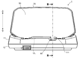
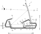
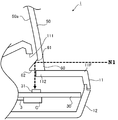
- FIG. 3 is a schematic cross-sectional view of the HUD device taken along line BB shown in FIG. 2. It is a principal part enlarged view of the HUD apparatus shown in FIG. 3, and is a figure for demonstrating mainly the function of a light guide.
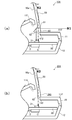
- A is a principal part enlarged view of the HUD apparatus which concerns on the modification 1.
- FIG. B is a principal part enlarged view of the HUD apparatus which concerns on the modification 2.
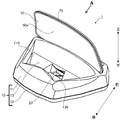
- the HUD device 1 includes a case body 10, a display device 20, a circuit board 30, a reflection unit 40, a combiner 50, and a light guide formed integrally with the combiner 50.
- a body 60 and a cover member 70 are provided.
- the HUD device 1 is configured as, for example, a stationary HUD device that is mounted on a dashboard of a vehicle (for example, above an instrument panel).
- the upper direction is “up”
- the lower direction is “lower”
- the front direction is “front”
- the rear direction is “rear”, as viewed from the observer 2 viewing the display image displayed by the HUD device 1.
- Each part of the HUD device will be described as appropriate.
- the case body 10 includes an upper case 11, a lower case 12, and an intermediate case 13.
- a first opening 110 is formed in the upper case 11, and the upper case 11 and the lower case 12 are connected to form a shape like a box with an upper opening.
- the display 20, the circuit board 30, and the inner case 13 are accommodated in the box shape.
- the upper case 11 has an attached portion (not shown) that is a portion to which the combiner 50 is attached on the front side of the first opening 110.
- the lower end portion of the combiner 50 is attached to the attached portion with a screw.
- the upper case 11 holds the combiner 50.
- the held combiner 50 is configured to extend upward from the upper case 11.
- the upper case 11 is formed with a second opening 111 that exposes the light guide 60 forward and allows incident light (external light N ⁇ b> 1 described later) to pass through the case body 10. .
- the middle case 13 is placed on the lower case 12.
- the lower case 12 is formed with a recess 121 having a shape corresponding to the lower end of the reflecting portion 40.
- the reflective portion 40 is held by the concave portion 121 and a part of the inner case 13 (the inner surface on the rear side) (for example, the reflective portion 40 has one end inserted into the concave portion 121, and the rear surface is It is held by being fixed to the middle case 13 with an adhesive tape or the like).
- the middle case 13 is a substantially cylindrical member, and the display device 20 is disposed on a part of the outer surface (the right side in FIG. 3).
- the middle case 13 is formed with an emission port 130 that is a hole for exposing the display surface of the display 20.
- a transparent window member that covers the emission port 130 may be provided in the middle case 13.
- the display 20 emits display light L representing a display image for notifying display information such as a vehicle speed and a travel distance.
- a transmissive liquid crystal display including a liquid crystal panel and a light source for backlight, Or it comprises a self-luminous display.
- the circuit board 30 is a control unit (not shown) including a microcomputer, a graphic display controller (GDC), and the like including a CPU and a storage unit such as a ROM on a plate-like base material made of a resin containing glass fiber. Is a printed circuit board on which is mounted.
- the circuit board 30 is fixed to the lower case 12 by an attachment member (not shown), and is located in front of the display 20 and between the upper case 11 and the lower case 12.
- the circuit board 30 and the display device 20 are conductively connected via an FPC (Flexible Printed Circuit) 3. One end of the FPC 3 is connected to the circuit board 30 via the connector C.
- FPC Flexible Printed Circuit
- the control unit obtains vehicle state information transmitted through a communication line from an external device (not shown) such as a vehicle ECU (Electronic Control Unit), and drives the display device 20 in response thereto (that is, the display device). 20 to display a predetermined display image).
- an external device not shown
- a vehicle ECU Electronic Control Unit
- the circuit board 30 is mounted with a photosensor 31, an amplifier circuit (not shown), a drive circuit (not shown) for driving the display 20, and the like.
- the optical sensor 31 is for detecting the brightness of the light that has arrived.
- the optical sensor 31 faces an opposing surface 62 of the light guide 60 described later, and the optical axis of the light incident on the optical sensor 31 is in the vertical direction. It is arrange
- the optical sensor 31 supplies a detection signal indicating the brightness of the reached light to the amplification circuit, and the amplification circuit amplifies the detection signal detected by the optical sensor 31 and supplies the amplified detection signal to the control unit.
- the control unit Based on the acquired detection signal, the control unit adjusts the luminance of the display image displayed by the display device 20 via the drive circuit. For example, when the value indicating the brightness of the light received by the optical sensor 31 is smaller than a threshold value (stored in advance), it is estimated that the background is dark, so the display brightness of the display 20 is set to a predetermined frequency. Just make it higher. Specifically, for example, when the display device 20 is composed of a transmissive liquid crystal display, the luminance of the backlight light source is increased.
- the reflector 40 is located on the display side of the display device 20, that is, on the emission side of the display light L, and reflects the reached display light L toward the combiner 50.
- the reflecting portion 40 is made of, for example, a resin molded product deposited with aluminum, and has a reflecting surface configured as a curved surface that efficiently reflects the display light L from the display device 20 to the combiner 50 (in FIG. 3, the reflecting surface is a reflecting surface).
- the surface is schematically represented as a plane).
- the reflection part 40 is arrange
- the display light L emitted from the display device 20 passes through the emission port 130 and reaches the reflection unit 40. Then, the display light L reflected by the reflection unit 40 passes through the first opening 110 of the upper case 11 and travels toward the combiner 50.
- the combiner 50 includes a plate-shaped half mirror having a curved surface, a hologram element, and the like. As described above, the combiner 50 is attached to the upper case 11, and the concave surface 50 a substantially faces the reflective surface of the reflective portion 40. As shown in FIG. 3, the combiner 50 changes the optical path of the incident display light L after being reflected by the reflecting section 40 (if the half mirror is used as the combiner 50, the optical path of the display light L is changed by reflection, When a hologram element is used, the optical path of the display light L is changed by diffraction).
- the concave surface 50a of the combiner 50 has a function of condensing the display light L and is a curved surface that can form a virtual image farther forward (for example, about 1 m ahead of the combiner 50) than when the light is simply reflected. It is configured.
- the combiner 50 forms a virtual image of the display image at the front position F and transmits light from the front, whereby the HUD device 1 allows the observer to view both the virtual image and the outside scene actually present in front. 2 can be visually recognized.
- the light guide 60 is formed integrally with the combiner 50, and protrudes downward from a part of the lower end portion of the combiner 50, for example, as shown in FIG. 2 (for reference, the combiner 50 is shown in FIG.
- the lower end UL of is represented by a dotted line).
- the cross-sectional shape of the light guide 60 is formed in a substantially triangular shape as shown in FIG.
- the light guide 60 guides external light from a predetermined direction toward the optical sensor 31, and is formed to include a reflective surface 61 and an opposing surface 62.
- the reflecting surface 61 is an inclined surface on the rear side of the light guide body 60 (for example, inclined by 45 ° with respect to the front-rear direction), and is externally incident on the light guide body 60 from the front as shown in FIG.
- Light N1 (hereinafter, “N1” is attached to outside light from the front) is efficiently reflected downward.
- 4 is an enlarged view of the main part of the schematic cross-sectional view of the HUD device 1 shown in FIG. 3, but in FIG. 4, the hatching indicating the cross-section is omitted (see FIG. The same applies to (b)).
- the facing surface 62 is a lower surface of the light guide 60 and is a surface facing the optical sensor 31 in the vertical direction. Further, the facing surface 62 functions as an emission surface that emits light guided downward by the light guide 60 to the outside.
- a part of the front part 11F which is a part ahead of the combiner 50 of the upper case 11 is a cover part 112 which covers a part of the opposing surface 62 from the lower side.
- the upper case 11 is configured such that the cover portion 112 is reflected by the reflecting surface 61, is emitted from the facing surface 62, and covers only the portion that does not obstruct the optical path of the external light N ⁇ b> 1 toward the optical sensor 31.
- the cover member 70 is a member that covers the side surface of the combiner 50 and is made of a light shielding resin material.
- the cover member 70 protects the side surface of the combiner 50 (for example, protection from impact), and prevents external light from entering the combiner 50 from the side surface (in particular, the upper side surface above the optical sensor 31). Is provided to do.
- the cover member 70 is configured not to cover a portion of the light guide 60.
- the optical path of the external light reflected by the reflecting surface 61 and going downward is not obstructed, and the external light incident from the upper side surface of the combiner 50 (that is, going downward without being reflected by the reflecting surface 61).
- the cover 112 may be provided so as to block the optical path of outside light.
- External light N1 from the front of the combiner 50 enters from the front surface of the light guide 60 and is reflected by the reflecting surface 61.
- the reflected external light N1 is guided into the light guide 60 and directed downward, and is emitted from the facing surface 62.
- the external light N1 emitted from the facing surface 62 reaches the optical sensor 31 that faces the facing surface 62.
- the optical sensor 31 detects the brightness of the external light N1, and the control unit according to the brightness adjusts the luminance of the display 20 as appropriate based on the detection result as described above.
- the cover member 70 is provided on the side surface of the combiner 50, external light does not enter from the side surface (particularly, the upper surface of the upper portion of the optical sensor 31).
- the external light N1 from the front can be mainly sensed.
- the front of the combiner 50 is the background direction when the observer 2 visually recognizes the display image, the brightness of the external light N1 that can be regarded as almost the brightness of the background can be effectively sensed in this way.
- the brightness of the projection direction is adjusted before the vehicle exits the tunnel.
- the brightness of the projected image can be adjusted to an appropriate brightness.
- the HUD device 101 includes not only the external light N1 from the front but also the external light N2 from above (hereinafter referred to as “N2” for external light from above). .) Is also detected.
- the cover member 70 is not provided, or at least a portion of the cover member 70 located above the optical sensor 31 (near the line BB shown in FIG. 2) The part of Of course, in this case, the cover portion 112 is provided so as not to obstruct the optical path of the external light N2 incident from the upper side surface of the combiner 50.
- Such a configuration is more effective when, for example, it is possible to reflect the brightness of the background more by detecting the external light N2 from the upper direction depending on the in-vehicle environment.
- the HUD device 201 according to the modified example 2 is configured to detect the external light N2 from above without detecting the external light N1 from the front as much as possible.
- the cover member 70 is not provided, or at least a portion of the cover member 70 located above the optical sensor 31 may be cut out.
- the cover part 112 is provided so that the optical path of the external light N2 which injected from the upper surface of the combiner 50 may not be prevented.
- the light guide 260 according to the modification 2 is not formed with the reflection surface 61 as described above. Such a configuration is effective, for example, when the external light N2 from above is dominant for the brightness of the background due to some factor.
- the HUD device 1 (or 101, 201) described above has a display 20 that emits display light L representing a display image, and a concave surface 50a on which the display light L emitted from the display 20 is incident.
- the displayed light L is condensed and the observer 2 is made to visually recognize the display image superimposed on the front background from the concave surface 50a side.
- the combiner 50 is positioned below the combiner 50, and the brightness of the reached light is detected.
- the combiner 50 has a light guide 60 integrated with the combiner 50 at the lower end thereof, and the light guide 60 is in the vertical direction.
- the opposite surface 62 that faces the outside guides the outside light from at least one of the front and the upper of the incident outside light, and emits the outside light guided downward from the facing surface 62. Emitted from the opposite surface 62 It was to detect the brightness of the light.
- the configuration of the HUD device 1 (or 101, 201) is simple. In addition, since the number of parts can be reduced, the cost can be reduced.
- the light guide body 60 includes the reflection surface 61 that reflects the external light N1 incident from the front toward the lower side. Light is emitted from the facing surface 62. For this reason, as described above, the brightness in the background direction can be detected effectively.
- this invention is not limited by the said embodiment, its modification (modifications 1 and 2), and drawing. Of course, changes (including deletion of components) can be added to these.
- an example in which the angle of the reflection surface 61 included in the light guide 60 is 45 °, for example, is not limited thereto. It is also possible to adjust (suppress) the amount of external light N1 reaching the optical sensor 31 by shifting the inclination angle of the reflecting surface 61 from 45 °.
- the present invention is not limited thereto.
- the HUD device may be configured such that the display emits the display light L directly toward the combiner. In this case, the display device and the combiner are provided so as to face each other, and the reflection unit 40 is unnecessary.
- the present invention is not limited to this.
- the HUD device 1 can also be installed near the driver's seat of other vehicles such as ships and aircraft.
- the present invention is not limited to the one installed near the driver's seat of the vehicle, but can be applied to a desktop interior installed indoors.
- the HUD device 1 is described as a stationary type.
- the HUD device 1 may be configured integrally with a dashboard of a vehicle, for example.
- the head-up display device for a vehicle has been described as an example of the application.
- the embodiment is not limited to the vehicle, but is applied to a special vehicle such as a ship or an agricultural machine or a construction machine. Is possible.
Landscapes
- Engineering & Computer Science (AREA)
- Physics & Mathematics (AREA)
- Chemical & Material Sciences (AREA)
- Mechanical Engineering (AREA)
- Combustion & Propulsion (AREA)
- Transportation (AREA)
- General Physics & Mathematics (AREA)
- Computer Hardware Design (AREA)
- Theoretical Computer Science (AREA)
- Optics & Photonics (AREA)
- Crystallography & Structural Chemistry (AREA)
- Instrument Panels (AREA)
- Multimedia (AREA)
Description
表示画像を表す表示光を出射する表示器と、
前記表示器が出射した表示光が入射する凹面を有し、入射した表示光を集光して観察者に前記凹面側から前記表示画像を前方の背景と重ねて視認させるコンバイナと、
前記コンバイナの下方に位置し、到達した光の明るさを検出する光検出部と、を備え、
前記コンバイナは、その下端部に、前記コンバイナと一体である導光体を有し、
前記導光体は、上下方向において前記光検出部と向かい合う対向面を有し、入射した外光のうち前方と上方との少なくとも一方からの外光を下方に導き、下方に導いた外光を前記対向面から出射し、
前記光検出部は、前記対向面から出射された光の明るさを検出する、
ことを特徴とする。
前記導光体は、前方から入射した外光を下方に向けて反射させる反射面を有し、
前記反射面で反射した外光を前記対向面から出射する、ようにしてもよい。
前記対向面の一部を下側から覆い、前記コンバイナの上方から前記導光体を通過し、下方に向かう光の光路を妨げる覆い部を備えていてもよい。
前記コンバイナの上側面を覆う遮光性のカバー部材が設けられ、前記上側面から外光が入射しないように構成されている、ようにしてもよい。
前記光検出部が検出した光の明るさに基づいて前記表示器の表示輝度を調整する調整手段を備えていてもよい。
HUD装置1は、例えば、車両のダッシュボード上(例えば、インストルメントパネル上方)に取り付けられる据え置き型のHUD装置として構成されている。以下の説明では、HUD装置1が表示する表示画像を視認する観察者2から見て、上方向を「上」、下方向を「下」、前方向を「前」、後ろ方向を「後」として(図1、図3等の両端矢印参照)、適宜、HUD装置を構成する各部を説明する。
また、上ケース11には、導光体60を前方に露出させるとともに、入射した光(後述する外光N1)をケース体10内部に通過させるための第2の開口部111が形成されている。
光センサ31は、到達した光の明るさを検出するためのものであり、後述する導光体60の対向面62と対向し、且つ、光センサ31に入射する光の光軸が上下方向に沿うように配設されている(図4参照)。光センサ31は、到達した光の明るさを示す検出信号を増幅回路に供給し、増幅回路は、光センサ31が検出した検出信号を増幅して、前記制御部に供給する。制御部は、取得した検出信号に基づいて、駆動回路を介して、表示器20が表示する表示画像の輝度を調整する。例えば、光センサ31が受けた光の明るさを示す値が、閾値(予め記憶されている)よりも小さい場合は、背景が暗いと推測されるため、表示器20の表示輝度を所定の度数だけ高くする。具体的には、例えば、表示器20が透過型液晶ディスプレイからなる場合、バックライト用光源の輝度を高くする。
そして、反射部40で反射した表示光Lは、上ケース11の第1の開口部110を通過してコンバイナ50に向かう。
導光体60は、所定の方向からの外光を光センサ31に向けて導くものであり、反射面61と、対向面62とを有して形成されている。
なお、カバー部材70を設けずに、前述の覆い部112によって、コンバイナ50の上側面から入射する光を光センサ31に極力到達させないようにすることもできる。このようにするには、反射面61で反射して、下方に向かう外光の光路は妨げず、コンバイナ50の上側面から入射した外光(つまり、反射面61で反射せずに下方に向かう外光)の光路を塞ぐように、覆い部112を設ければよい。
コンバイナ50の前方からの外光N1は、導光体60の前面から入射し、反射面61で反射する。反射した外光N1は、導光体60内部に導かれ下方に向かい、対向面62から出射される。
対向面62から出射された外光N1は、対向面62と向かい合う光センサ31に到達する。そして、光センサ31は、外光N1の明るさを検出し、これに応じた制御部は、前述したように、検出結果に基づいて表示器20の輝度を、適宜、調整する。
変形例1に係るHUD装置101は、図5(a)に示すように、前方からの外光N1だけでなく、上方からの外光N2(以下、上方からの外光には、“N2”と符号を付す。)も検出するように構成されている。
上方からの外光N2も検出させるためには、カバー部材70を設けないか、又は、カバー部材70のうち、少なくとも、光センサ31の上方に位置する部分(図2に示すB-B線近傍の部分)を切り欠けばよい。無論、この場合には、覆い部112は、コンバイナ50の上側面から入射した外光N2の光路を妨げないように設けられる。
このような構成は、例えば、車内環境により、上方向からの外光N2も検出したほうが、より背景の明るさを反映できる場合などに有効である。
変形例2に係るHUD装置201は、図5(b)に示すように、前方からの外光N1を極力検出させずに、上方からの外光N2を検出できるように構成されている。
この場合も、変形例1と同様に、カバー部材70を設けないか、又は、カバー部材70のうち、少なくとも、光センサ31の上方に位置する部分を切り欠けばよい。そして、覆い部112は、コンバイナ50の上側面から入射した外光N2の光路を妨げないように設けられる。また、このように、上方からの外光N2のみを検出するために、変形例2に係る導光体260には、上記のような反射面61が形成されていない。
このような構成は、例えば、なんらかの要因により、上方からの外光N2が背景の明るさにとって支配的になっている場合などに有効である。
このように、光センサに光を導くため導光体が、コンバイナと一体的に構成されているため、HUD装置1(ないしは、101、201)は、構成が簡潔である。また、部品点数を減らすことも可能であるため、コストの削減を図ることも可能である。
2 …観察者
10 …ケース体
11 …上ケース
11F…前方部
110…第1の開口部
111…第2の開口部
112…覆い部
12 …下ケース
121…凹部
13 …中ケース
130…出射口
20 …表示器
30 …回路基板
31 …光センサ
40 …反射部
50 …コンバイナ
50a…凹面
60 …導光体
61 …反射面
62 …対向面
70 …カバー部材
Claims (5)
- 表示画像を表す表示光を出射する表示器と、
前記表示器が出射した表示光が入射する凹面を有し、入射した表示光を集光して観察者に前記凹面側から前記表示画像を前方の背景と重ねて視認させるコンバイナと、
前記コンバイナの下方に位置し、到達した光の明るさを検出する光検出部と、を備え、
前記コンバイナは、その下端部に、前記コンバイナと一体である導光体を有し、
前記導光体は、上下方向において前記光検出部と向かい合う対向面を有し、入射した外光のうち前方と上方との少なくとも一方からの外光を下方に導き、下方に導いた外光を前記対向面から出射し、
前記光検出部は、前記対向面から出射された光の明るさを検出する、
ことを特徴とするヘッドアップディスプレイ装置。 - 前記導光体は、前方から入射した外光を下方に向けて反射させる反射面を有し、
前記反射面で反射した外光を前記対向面から出射する、
ことを特徴とする請求項1に記載のヘッドアップディスプレイ装置。 - 前記対向面の一部を下側から覆い、前記コンバイナの上方から前記導光体を通過し、下方に向かう光の光路を妨げる覆い部を備える、
ことを特徴とする請求項1又は2に記載のヘッドアップディスプレイ装置。 - 前記コンバイナの上側面を覆う遮光性のカバー部材が設けられ、前記上側面から外光が入射しないように構成されている、
ことを特徴とする請求項1又は2に記載のヘッドアップディスプレイ装置。 - 前記光検出部が検出した光の明るさに基づいて前記表示器の表示輝度を調整する調整手段を備える、
ことを特徴とする請求項1乃至4のいずれか1項に記載のヘッドアップディスプレイ装置。
Priority Applications (5)
| Application Number | Priority Date | Filing Date | Title |
|---|---|---|---|
| US14/388,737 US9242604B2 (en) | 2012-03-29 | 2013-03-07 | Head-up display device |
| KR1020147027744A KR20140141629A (ko) | 2012-03-29 | 2013-03-07 | 헤드업 디스플레이 장치 |
| IN8234DEN2014 IN2014DN08234A (ja) | 2012-03-29 | 2013-03-07 | |
| CN201380016253.1A CN104204903B (zh) | 2012-03-29 | 2013-03-07 | 平视显示装置 |
| EP13768908.9A EP2833194B1 (en) | 2012-03-29 | 2013-03-07 | Heads-up display device |
Applications Claiming Priority (2)
| Application Number | Priority Date | Filing Date | Title |
|---|---|---|---|
| JP2012078120A JP5998578B2 (ja) | 2012-03-29 | 2012-03-29 | ヘッドアップディスプレイ装置 |
| JP2012-078120 | 2012-03-29 |
Publications (1)
| Publication Number | Publication Date |
|---|---|
| WO2013146160A1 true WO2013146160A1 (ja) | 2013-10-03 |
Family
ID=49259428
Family Applications (1)
| Application Number | Title | Priority Date | Filing Date |
|---|---|---|---|
| PCT/JP2013/056261 Ceased WO2013146160A1 (ja) | 2012-03-29 | 2013-03-07 | ヘッドアップディスプレイ装置 |
Country Status (7)
| Country | Link |
|---|---|
| US (1) | US9242604B2 (ja) |
| EP (1) | EP2833194B1 (ja) |
| JP (1) | JP5998578B2 (ja) |
| KR (1) | KR20140141629A (ja) |
| CN (1) | CN104204903B (ja) |
| IN (1) | IN2014DN08234A (ja) |
| WO (1) | WO2013146160A1 (ja) |
Cited By (2)
| Publication number | Priority date | Publication date | Assignee | Title |
|---|---|---|---|---|
| EP3165959A4 (en) * | 2014-07-01 | 2017-10-04 | Ricoh Company, Ltd. | Display device and vehicle |
| CN112930275A (zh) * | 2018-07-30 | 2021-06-08 | 法雷奥舒适驾驶助手公司 | 带有光传感器的显示器 |
Families Citing this family (33)
| Publication number | Priority date | Publication date | Assignee | Title |
|---|---|---|---|---|
| JP6349632B2 (ja) * | 2013-06-24 | 2018-07-04 | 日本精機株式会社 | ヘッドアップディスプレイ装置 |
| JP2015127170A (ja) * | 2013-12-27 | 2015-07-09 | パイオニア株式会社 | ヘッドアップディスプレイ、制御方法、プログラム、及び記憶媒体 |
| JP5957711B2 (ja) * | 2013-12-27 | 2016-07-27 | パナソニックIpマネジメント株式会社 | 表示装置および表示ユニット |
| CN104914574B (zh) * | 2014-03-11 | 2018-12-14 | 鸿富锦精密工业(深圳)有限公司 | 抬头显示装置 |
| CN103885183B (zh) * | 2014-03-12 | 2017-01-04 | 惠州市华阳多媒体电子有限公司 | 可回收的车载抬头显示器及车辆 |
| EP2930048A1 (en) * | 2014-04-10 | 2015-10-14 | Johnson Controls Automotive Electronics SAS | Head up display projecting visual information onto a screen |
| JP2015214246A (ja) * | 2014-05-09 | 2015-12-03 | カルソニックカンセイ株式会社 | 車両用表示装置 |
| JP6284153B2 (ja) * | 2014-06-12 | 2018-02-28 | 矢崎総業株式会社 | 外光導入部材及び車両用表示装置 |
| DE112015002757B4 (de) | 2014-06-12 | 2021-07-29 | Yazaki Corporation | Blendenkörper und Fahrzeuganzeigeeinrichtung |
| DE102014019160B4 (de) * | 2014-12-19 | 2021-04-29 | Audi Ag | Verfahren zum Verringern einer Reflexion beim Betreiben eines Head-up-Displays eines Kraftfahrzeugs, Head-up-Display, und Kraftfahrzeug mit einem Head-up-Display |
| TWI572503B (zh) * | 2015-02-24 | 2017-03-01 | 晶典有限公司 | 行車平視投影儀系統 |
| TWI554785B (zh) * | 2015-03-19 | 2016-10-21 | 尚立光電股份有限公司 | 具不對稱稜鏡之顯示裝置及其抬頭顯示裝置 |
| DE102016209526A1 (de) * | 2015-06-12 | 2016-12-15 | Ford Global Technologies, Llc | Projektionseinrichtung und Verfahren zum Projizieren eines virtuellen Bilds in einen Sichtbereich eines Fahrers eines Fahrzeugs |
| JP6595250B2 (ja) * | 2015-08-06 | 2019-10-23 | 株式会社ポラテクノ | ヘッドアップディスプレイ装置 |
| JP6661955B2 (ja) * | 2015-10-08 | 2020-03-11 | 株式会社リコー | 表示装置 |
| KR102363992B1 (ko) * | 2015-11-24 | 2022-02-18 | 현대모비스 주식회사 | 차량용 헤드업 디스플레이 장치 |
| US20170148216A1 (en) * | 2015-11-25 | 2017-05-25 | Continental Automotive Systems, Inc. | Display system adjustable based on background |
| EP3403133B1 (en) * | 2016-01-12 | 2022-05-11 | Magic Leap, Inc. | Beam angle sensor in virtual/augmented reality system |
| WO2017147158A1 (en) * | 2016-02-22 | 2017-08-31 | Navdy, Inc. | Head-up display device and method for constructing the same |
| FR3050541B1 (fr) * | 2016-04-26 | 2019-07-12 | Valeo Comfort And Driving Assistance | Afficheur |
| FR3050542B1 (fr) * | 2016-04-26 | 2019-07-12 | Valeo Comfort And Driving Assistance | Afficheur comprenant un capteur de lumiere |
| JP6559105B2 (ja) * | 2016-08-31 | 2019-08-14 | 富士フイルム株式会社 | ヘッドアップディスプレイ装置 |
| CN106547094A (zh) * | 2016-11-25 | 2017-03-29 | 刘涛 | 利用汽车前挡风玻璃实现抬头显示的设备 |
| CN106772967A (zh) * | 2016-12-06 | 2017-05-31 | 中国航空工业集团公司洛阳电光设备研究所 | 一种透视型演讲显示光学系统 |
| CN108237975B (zh) * | 2016-12-23 | 2021-06-11 | 大众汽车(中国)投资有限公司 | 一种用于光照调节的方法和装置 |
| KR102730968B1 (ko) * | 2017-02-14 | 2024-11-19 | 현대모비스 주식회사 | 개별 제어가 가능한 다중 표시영역을 구현하는 헤드 업 디스플레이 장치 및 헤드 업 디스플레이 장치의 표시 제어 방법 |
| US20190033582A1 (en) * | 2017-07-31 | 2019-01-31 | Benoit CHAUVEAU | Embedded sensor in a heads-up display (hud) panel |
| USD888633S1 (en) * | 2017-10-17 | 2020-06-30 | Lg Electronics Inc. | Head-up display for car |
| USD900689S1 (en) * | 2017-10-17 | 2020-11-03 | Lg Electronics Inc. | Head-up display for car |
| JP6995646B2 (ja) * | 2018-01-26 | 2022-01-14 | 本田技研工業株式会社 | 表示装置 |
| CN109521564A (zh) * | 2018-11-20 | 2019-03-26 | 惠州市华阳多媒体电子有限公司 | 一种车载多屏全息投影系统 |
| CN112147779B (zh) * | 2019-06-26 | 2025-06-20 | 比亚迪股份有限公司 | 用于车辆的车载抬头显示系统及具有其的车辆 |
| USD1106012S1 (en) * | 2023-09-25 | 2025-12-16 | Lg Electronics Inc. | Head-up display for cars |
Citations (3)
| Publication number | Priority date | Publication date | Assignee | Title |
|---|---|---|---|---|
| JPH0425816A (ja) * | 1990-05-22 | 1992-01-29 | Nissan Motor Co Ltd | 前景輝度検出装置 |
| JPH06144081A (ja) * | 1992-10-30 | 1994-05-24 | Kansei Corp | 車両用自動調光機能を備えたヘッドアップディスプレイ装置 |
| JPH0954276A (ja) | 1995-08-11 | 1997-02-25 | Denso Corp | ヘッドアップディスプレイ |
Family Cites Families (6)
| Publication number | Priority date | Publication date | Assignee | Title |
|---|---|---|---|---|
| CA954347A (en) * | 1970-06-22 | 1974-09-10 | Robert K. Kirschner | Head-up display |
| JPH0943531A (ja) * | 1995-07-31 | 1997-02-14 | Fujitsu Ltd | 車両用表示装置 |
| JP4089075B2 (ja) * | 1999-03-30 | 2008-05-21 | 株式会社島津製作所 | ヘッドアップディスプレイシステム |
| US7561966B2 (en) * | 2003-12-17 | 2009-07-14 | Denso Corporation | Vehicle information display system |
| JP5012640B2 (ja) * | 2008-04-25 | 2012-08-29 | 株式会社島津製作所 | 表示装置 |
| DE102009053825A1 (de) * | 2009-11-18 | 2011-05-19 | Trw Automotive Electronics & Components Gmbh | Optische Sensorvorrichtung zur Detektion von Umgebungslicht |
-
2012
- 2012-03-29 JP JP2012078120A patent/JP5998578B2/ja not_active Expired - Fee Related
-
2013
- 2013-03-07 EP EP13768908.9A patent/EP2833194B1/en not_active Not-in-force
- 2013-03-07 WO PCT/JP2013/056261 patent/WO2013146160A1/ja not_active Ceased
- 2013-03-07 CN CN201380016253.1A patent/CN104204903B/zh not_active Expired - Fee Related
- 2013-03-07 US US14/388,737 patent/US9242604B2/en not_active Expired - Fee Related
- 2013-03-07 KR KR1020147027744A patent/KR20140141629A/ko not_active Ceased
- 2013-03-07 IN IN8234DEN2014 patent/IN2014DN08234A/en unknown
Patent Citations (3)
| Publication number | Priority date | Publication date | Assignee | Title |
|---|---|---|---|---|
| JPH0425816A (ja) * | 1990-05-22 | 1992-01-29 | Nissan Motor Co Ltd | 前景輝度検出装置 |
| JPH06144081A (ja) * | 1992-10-30 | 1994-05-24 | Kansei Corp | 車両用自動調光機能を備えたヘッドアップディスプレイ装置 |
| JPH0954276A (ja) | 1995-08-11 | 1997-02-25 | Denso Corp | ヘッドアップディスプレイ |
Non-Patent Citations (1)
| Title |
|---|
| See also references of EP2833194A4 |
Cited By (3)
| Publication number | Priority date | Publication date | Assignee | Title |
|---|---|---|---|---|
| EP3165959A4 (en) * | 2014-07-01 | 2017-10-04 | Ricoh Company, Ltd. | Display device and vehicle |
| US10293689B2 (en) | 2014-07-01 | 2019-05-21 | Ricoh Company, Ltd. | Display device, vehicle |
| CN112930275A (zh) * | 2018-07-30 | 2021-06-08 | 法雷奥舒适驾驶助手公司 | 带有光传感器的显示器 |
Also Published As
| Publication number | Publication date |
|---|---|
| EP2833194B1 (en) | 2018-06-06 |
| US9242604B2 (en) | 2016-01-26 |
| KR20140141629A (ko) | 2014-12-10 |
| US20150035725A1 (en) | 2015-02-05 |
| CN104204903A (zh) | 2014-12-10 |
| EP2833194A4 (en) | 2017-04-12 |
| JP2013205817A (ja) | 2013-10-07 |
| CN104204903B (zh) | 2016-08-31 |
| EP2833194A1 (en) | 2015-02-04 |
| IN2014DN08234A (ja) | 2015-05-15 |
| JP5998578B2 (ja) | 2016-09-28 |
Similar Documents
| Publication | Publication Date | Title |
|---|---|---|
| JP5998578B2 (ja) | ヘッドアップディスプレイ装置 | |
| JP6349632B2 (ja) | ヘッドアップディスプレイ装置 | |
| KR101823180B1 (ko) | 차량용 헤드업 디스플레이 장치 | |
| JP5919724B2 (ja) | 車両用ヘッドアップディスプレイ装置 | |
| CN113741031B (zh) | 车载显示装置 | |
| US9658450B2 (en) | Vehicle heads-up display device | |
| WO2013129041A1 (ja) | ヘッドアップディスプレイ装置 | |
| JP2012063524A (ja) | 車両用ヘッドアップディスプレイ装置 | |
| KR20190069638A (ko) | 클러스터 일체형 헤드업 디스플레이 장치 | |
| CN105313780A (zh) | 车辆中的驾驶员信息系统 | |
| JP6287017B2 (ja) | ヘッドアップディスプレイ装置 | |
| JP2018030522A (ja) | ヘッドアップディスプレイ装置 | |
| JP2019006180A (ja) | 表示装置 | |
| JP2015157509A (ja) | 車両用警告装置および車両用警告ユニット | |
| JP7769871B2 (ja) | ヘッドアップディスプレイ | |
| JP2017149354A (ja) | ヘッドアップディスプレイ装置 | |
| JP2015118165A (ja) | 車両用計器 | |
| JP2005326723A (ja) | 車両用ヘッドアップディスプレイ | |
| US20250291182A1 (en) | Vehicle projection display device | |
| JP2004249752A (ja) | 車両用表示装置 | |
| JP2024053592A (ja) | ヘッドアップディスプレイ装置 | |
| KR20230089459A (ko) | 헤드업 디스플레이장치 | |
| JP2022149010A (ja) | インストルメントパネル、車両用表示装置、及びベゼル体 | |
| JP2021128258A (ja) | 表示装置 | |
| JP2008111887A (ja) | ヘッドアップディスプレイ装置 |
Legal Events
| Date | Code | Title | Description |
|---|---|---|---|
| 121 | Ep: the epo has been informed by wipo that ep was designated in this application |
Ref document number: 13768908 Country of ref document: EP Kind code of ref document: A1 |
|
| WWE | Wipo information: entry into national phase |
Ref document number: 14388737 Country of ref document: US |
|
| ENP | Entry into the national phase |
Ref document number: 20147027744 Country of ref document: KR Kind code of ref document: A |
|
| WWE | Wipo information: entry into national phase |
Ref document number: 2013768908 Country of ref document: EP |
|
| NENP | Non-entry into the national phase |
Ref country code: DE |