WO2013146305A1 - Dispositif d'injection d'une solution médicamenteuse dans un corps - Google Patents
Dispositif d'injection d'une solution médicamenteuse dans un corps Download PDFInfo
- Publication number
- WO2013146305A1 WO2013146305A1 PCT/JP2013/057240 JP2013057240W WO2013146305A1 WO 2013146305 A1 WO2013146305 A1 WO 2013146305A1 JP 2013057240 W JP2013057240 W JP 2013057240W WO 2013146305 A1 WO2013146305 A1 WO 2013146305A1
- Authority
- WO
- WIPO (PCT)
- Prior art keywords
- catheter
- drug solution
- main body
- discharge port
- diameter
- Prior art date
- Legal status (The legal status is an assumption and is not a legal conclusion. Google has not performed a legal analysis and makes no representation as to the accuracy of the status listed.)
- Ceased
Links
Images


Classifications
-
- A—HUMAN NECESSITIES
- A61—MEDICAL OR VETERINARY SCIENCE; HYGIENE
- A61M—DEVICES FOR INTRODUCING MEDIA INTO, OR ONTO, THE BODY; DEVICES FOR TRANSDUCING BODY MEDIA OR FOR TAKING MEDIA FROM THE BODY; DEVICES FOR PRODUCING OR ENDING SLEEP OR STUPOR
- A61M39/00—Tubes, tube connectors, tube couplings, valves, access sites or the like, specially adapted for medical use
- A61M39/02—Access sites
- A61M39/0208—Subcutaneous access sites for injecting or removing fluids
-
- A—HUMAN NECESSITIES
- A61—MEDICAL OR VETERINARY SCIENCE; HYGIENE
- A61M—DEVICES FOR INTRODUCING MEDIA INTO, OR ONTO, THE BODY; DEVICES FOR TRANSDUCING BODY MEDIA OR FOR TAKING MEDIA FROM THE BODY; DEVICES FOR PRODUCING OR ENDING SLEEP OR STUPOR
- A61M39/00—Tubes, tube connectors, tube couplings, valves, access sites or the like, specially adapted for medical use
- A61M39/02—Access sites
- A61M39/0247—Semi-permanent or permanent transcutaneous or percutaneous access sites to the inside of the body
-
- A—HUMAN NECESSITIES
- A61—MEDICAL OR VETERINARY SCIENCE; HYGIENE
- A61M—DEVICES FOR INTRODUCING MEDIA INTO, OR ONTO, THE BODY; DEVICES FOR TRANSDUCING BODY MEDIA OR FOR TAKING MEDIA FROM THE BODY; DEVICES FOR PRODUCING OR ENDING SLEEP OR STUPOR
- A61M39/00—Tubes, tube connectors, tube couplings, valves, access sites or the like, specially adapted for medical use
- A61M39/02—Access sites
- A61M39/0208—Subcutaneous access sites for injecting or removing fluids
- A61M2039/0229—Subcutaneous access sites for injecting or removing fluids having means for facilitating assembling, e.g. snap-fit housing or modular design
-
- A—HUMAN NECESSITIES
- A61—MEDICAL OR VETERINARY SCIENCE; HYGIENE
- A61M—DEVICES FOR INTRODUCING MEDIA INTO, OR ONTO, THE BODY; DEVICES FOR TRANSDUCING BODY MEDIA OR FOR TAKING MEDIA FROM THE BODY; DEVICES FOR PRODUCING OR ENDING SLEEP OR STUPOR
- A61M39/00—Tubes, tube connectors, tube couplings, valves, access sites or the like, specially adapted for medical use
- A61M39/02—Access sites
- A61M39/0247—Semi-permanent or permanent transcutaneous or percutaneous access sites to the inside of the body
- A61M2039/0273—Semi-permanent or permanent transcutaneous or percutaneous access sites to the inside of the body for introducing catheters into the body
-
- A—HUMAN NECESSITIES
- A61—MEDICAL OR VETERINARY SCIENCE; HYGIENE
- A61M—DEVICES FOR INTRODUCING MEDIA INTO, OR ONTO, THE BODY; DEVICES FOR TRANSDUCING BODY MEDIA OR FOR TAKING MEDIA FROM THE BODY; DEVICES FOR PRODUCING OR ENDING SLEEP OR STUPOR
- A61M39/00—Tubes, tube connectors, tube couplings, valves, access sites or the like, specially adapted for medical use
- A61M39/02—Access sites
- A61M39/0247—Semi-permanent or permanent transcutaneous or percutaneous access sites to the inside of the body
- A61M2039/0282—Semi-permanent or permanent transcutaneous or percutaneous access sites to the inside of the body with implanted tubes connected to the port
Definitions
- the present invention relates to a drug solution injector for injecting a drug solution into a patient's body, and more particularly to a subcutaneously implantable in-vivo drug solution injector used for treatment such as chemotherapy.
- a chemical injection therapy is performed in which a chemical is injected into the body.
- a drug injector has been proposed for use in such drug injection therapy.
- the chemical solution injector include, for example, Patent Document 1 (USP 4929236, Japanese Patent Publication No. 4-10832), Patent Document 2 proposed by the applicant of the present application (Japanese Patent Application Laid-Open No. 2004-350937), Patent Document 3 (Japanese Patent No. 3137360) and Patent Document 4 (Japanese Unexamined Patent Publication No. 2011-120737).
- These chemical liquid injectors include a main body, an internal space formed in the main body, a chemical liquid inlet and a chemical outflow passage communicating with the space, and a rubber plug attached to the chemical inlet.
- a chemical solution injection port having a (septum) and a catheter in which a lumen for chemical solution injection is formed In general, a chemical injection device inserts a catheter into the body, positions its distal end at the target site, cuts the excess portion on the proximal end side of the catheter, and connects the cut end to the chemical injection port After that, the drug solution injection port is fixed in the subcutaneous tissue and indwelled in the living body. For this reason, a catheter cannot be connected in advance to the drug solution injection port, and it is necessary to attach both of them during the operation. Moreover, since this embedding is performed by incising the skin, it is desirable to complete it early.
- the connecting portion of the chemical solution injection member connected to the catheter is a thin cylindrical portion.
- the thin cylindrical part is inserted in the end part of a catheter, and both are mounted
- the catheter is inserted into the body, and both the outer diameter and the inner diameter are small, and the mounting operation of both is not easy.
- the drug solution injector of Patent Document 4 includes a catheter and a drug solution injection member.
- the chemical liquid injection member includes an injection member main body having a chemical liquid inflow space communicating with the opening and a discharge port, and a seal portion that seals the opening.
- the injection member main body includes a flow part communicating with the drug solution inflow space, and the discharge port is provided inside the catheter proximal end mounting part and the catheter proximal end mounting part that enables insertion of the proximal end part of the catheter.
- the annular projecting portion has an annular tapered surface that is reduced in diameter toward one end, and an annular projecting end portion that has an inner diameter smaller than the outer diameter of the catheter and is formed at an acute angle. And it is effective in the point which can mount
- an object of the present invention is a chemical liquid injector comprising a catheter that can be inserted into the body and a chemical liquid injection member that is detachably mounted on the catheter, and mounting the port portion of the chemical liquid injection member to the catheter end. Therefore, it is an object of the present invention to provide an in-vivo drug injection device that is easy to remove and does not come off after being worn.
- An in-vivo medicinal solution injecting device comprising a catheter and a medicinal solution injecting member for detachably attaching the catheter, wherein the medicinal solution injecting device includes a cylindrical connection auxiliary member that can be inserted through the catheter and is attached to the catheter.
- the medicinal solution injecting member has an opening, a medicinal solution inflow space communicating with the opening, an infusion member main body attached to the injecting member main body, in communication with the medicinal solution inflow space, and the catheter.
- a discharge port that can be connected; and a seal portion that seals the opening of the injection member main body and allows the medicinal solution injection needle to be inserted, and the discharge port is inserted into the end opening of the catheter.
- An intra-catheter insertable portion having a distal end portion having a possible outer diameter, and an enlarged diameter portion located on the injection member main body side from the distal end portion and having a larger diameter than the distal end portion;
- the cylindrical connection auxiliary member includes a cylindrical main body having an inner diameter larger than the outer diameter of the catheter, an annular protrusion for holding a catheter provided in the cylindrical main body and having an inner diameter smaller than the outer diameter of the catheter; And when inserting and pushing the insertable portion of the discharge port into the one end of the catheter in a state where the one end of the catheter is positioned in the vicinity of one end of the cylindrical connection auxiliary member.
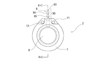
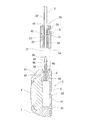
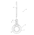
- FIG. 1 is a front view of an in-vivo drug solution injector of the present invention.
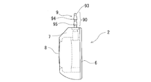
- FIG. 2 is an enlarged front view of a chemical solution injection member used in the in vivo drug solution injection device shown in FIG.
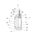
- FIG. 3 is a right side view of the chemical liquid injection member shown in FIG. 4 is a cross-sectional view taken along line AA in FIG.
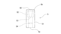
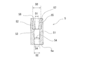
- FIG. 5 is an enlarged front view of a cylindrical connection assisting member used in the in-vivo drug solution injector shown in FIG.
- FIG. 6 is a longitudinal sectional view of the cylindrical connection auxiliary member shown in FIG.
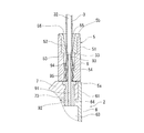
- FIG. 7 is an explanatory diagram for explaining the operation of the in-vivo drug solution injector of the present invention.
- FIG. 1 is a front view of an in-vivo drug solution injector of the present invention.
- FIG. 2 is an enlarged front view of a chemical solution injection member used in the in vivo drug solution injection device shown in FIG.
- FIG. 3 is a right side view of the chemical liquid
- FIG. 8 is an explanatory diagram for explaining the operation of the in-vivo drug injection device of the present invention.
- FIG. 9 is an explanatory diagram for explaining the operation of the in-vivo drug solution injector of the present invention.
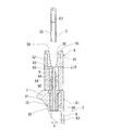
- FIG. 10 illustrates the chemical injection device of the present invention in a state where the catheter and the chemical injection member are connected.
- FIG. 11 is a longitudinal sectional view of a cylindrical connection assisting member used for an in-vivo drug solution injector according to another embodiment of the present invention.
- FIG. 12 is a longitudinal sectional view of a cylindrical connection assisting member used in an in-vivo drug solution injector according to another embodiment of the present invention.
- FIG. 13 is an explanatory view for explaining the form of the connecting portion of the in-vivo drug solution injector according to another embodiment of the present invention.
- the in-vivo drug solution injector of the present invention will be described with reference to the illustrated embodiment.
- the in-vivo drug injection device 1 of the present invention is an in-vivo drug injection device comprising a catheter 3 and a drug solution injection member 2 to which the catheter 3 is detachably attached.
- the drug solution injector 1 includes a cylindrical connection assisting member 5 that can be inserted through the catheter 3 and is attached to the catheter 3.
- the medicinal solution injecting member 2 is attached to the injecting member main body 6 having an opening and a medicinal solution inflow space 63 communicating with the opening, communicated with the medicinal solution inflow space 63, and connects the catheter 3.
- a possible discharge port 9 and a seal portion 8 that seals the opening of the injection member main body 6 and allows the medicinal solution injection needle to pierce are provided.
- the discharge port 9 has a distal end portion 93 having an outer diameter that can be inserted into the end opening of the catheter 3, and an enlarged diameter portion that is located closer to the injection member main body 6 than the distal end portion 93 and has a larger diameter than the distal end portion 93.
- the cylindrical connection assisting member 5 includes a cylindrical main body 51 having an inner diameter larger than the outer diameter of the catheter 3, and the cylindrical main body 51. And an annular protrusion 53 for holding a catheter having an inner diameter smaller than the outer diameter of three. Further, when the catheter 3 insertable portion 90 of the discharge port 9 is inserted and pushed into the one end 31 of the catheter 3 in a state where the one end 31 of the catheter 3 is in the vicinity of the one end 5 a of the cylindrical connection assisting member 5. The annular projecting portion 53 regulates the movement of the catheter 3 and assists the insertion of the discharge port 9 into the intra-catheter insertable portion 90 into the one end portion 31 of the catheter 3.
- the drug solution injector 1 of this embodiment has at least a tip portion in the body, specifically, a blood vessel (a vein or an artery), a vessel such as a bile duct, a ureter, and an epidural surface. It consists of a catheter 3 that can be inserted into the abdominal cavity under the arachnoid, a chemical solution injection member 2 that can be connected to the catheter 3, and a cylindrical connection auxiliary member that assists the connection between the catheter 3 and the chemical solution injection member 2.
- the catheter 3 used in the drug solution injector 1 of this embodiment is a tube body having an opening (one end) 31 and an internal lumen 32 as shown in FIGS. It has the same outer diameter and the same inner diameter throughout.
- the outer diameter E1 (see FIG. 9) of the catheter is preferably 0.6 to 3.0 mm, and particularly preferably 1.3 to 2.7 mm.
- the inner diameter E2 (see FIG. 9) of the catheter is preferably 0.3 to 2.0 mm, and particularly preferably 0.9 to 1.7 mm.
- the catheter 3 is flexible and preferably has a certain degree of elasticity.
- an annular projecting end formed at an acute angle of the annular projecting portion 53 for holding the catheter can bite into the outer surface.
- the catheter forming material include olefin-based elastomers (for example, polyethylene elastomers and polypropylene elastomers), polyesters such as polyethylene terephthalate, soft polyvinyl chloride, polyurethane and urethane-based elastomers, polyamides and amide-based elastomers (for example, polyamide elastomers).
- a flexible polymer material such as a fluororesin elastomer, an ethylene-vinyl acetate copolymer, and silicone rubber.
- the cylindrical connection assisting member 5 has a cylindrical main body 51 having an inner diameter larger than the outer diameter of the catheter 3 and a catheter holding member provided in the cylindrical main body 51 and having an inner diameter smaller than the outer diameter of the catheter 3.
- the length from the one end 5a of the cylindrical connection assisting member 5 to the annular projection 53 is longer than the length of the insertable portion 90 of the discharge port 9.
- annular protrusion 53 of the cylindrical connection auxiliary member 5 of the catheter 3 is in the state where the outer diameter and the inner diameter were reduced.
- the catheter 3 can be moved by pulling the catheter 3 in the direction of the one end 5a of the cylindrical connection auxiliary member 5, but the catheter 3 can be easily pulled even if it is pulled in the direction of the other end 5b of the cylindrical connection auxiliary member 5. It is not moving.
- the inner surface of the cylindrical connection auxiliary member 5 is a reduced diameter inner surface that decreases in a taper shape from the other end 5 b side of the cylindrical connection auxiliary member 5 toward the annular protrusion 53.
- the cylindrical connection assisting member 5 has a protrusion 54 provided between the one end 5a and the annular protrusion 53, and the protrusion 54 has a diameter-expanded catheter through which the expanded diameter portion 94 of the discharge port 9 has entered.
- the protrusion 54 is an annular protrusion, and its edge is chamfered so as not to damage the catheter.
- the protrusion part 54 is not limited to a cyclic
- the cylindrical connection assisting member 5 of this embodiment includes a cylindrical main body 51 and a cylindrical tip portion 52 inserted into the main body 51.
- the cylindrical main body 51 is generally cylindrical and extends in the direction of the other end from the one end 5 a and has a larger inner diameter than the outer diameter of the catheter 3.
- a chip portion mounting portion is configured to be able to store a tip member.
- the protrusion 54 is formed on the inner surface of the cylindrical portion of the cylindrical main body 51.
- the cylindrical tip portion 52 is inserted and fixed to the tip portion mounting portion of the cylindrical main body portion 51.
- the tip portion 52 has a flange portion 57 having a catheter insertion port 56 and a cylindrical portion extending from the flange portion 57 to one end side.
- An annular protrusion 53 for grasping the catheter is provided at one end of the cylindrical portion.
- the annular grasping portion 53 for grasping the catheter is provided at one end of the cylindrical tip portion 52.
- the annular grasping portion 53 for grasping the catheter has an annular tapered surface 55 whose diameter is reduced from the catheter insertion port 56 side toward one end side, and an annular projecting portion having an inner diameter smaller than the outer diameter of the catheter 3 and formed at an acute angle. 53.
- one end side of the annular projecting portion 53 is an upstanding surface that is substantially orthogonal to the central axis of the cylindrical main body portion 51.
- the inner surface of the cylindrical connection auxiliary member 5 is a reduced diameter inner surface that decreases in a taper shape from the other end 5 b side of the cylindrical connection auxiliary member 5 toward the annular protrusion 53.
- the catheter insertion port 56 provided in the cylindrical connection assisting member 5 has a diameter that increases toward the other end 5b that is the open end. For this reason, the insertion of the end of the catheter is easy.
- the catheter 3 is attached to the tubular connection assisting member 5 so as to penetrate the tubular connection assisting member 5, and the end of the above-described annular grasping portion 53 for grasping the catheter is formed at an acute angle.
- the annular protrusion 53 formed at an acute angle with the outer surface of the catheter 3 comes into contact with the wedge shape, so that it does not move easily.
- the inner diameter D1 of the annular protrusion 53 for holding the catheter is preferably 0.03 to 1 mm smaller than the outer diameter E1 of the catheter, in particular 0.1 to 0.38 mm smaller. Is preferred.
- the inner diameter D2 of the cylindrical connection auxiliary member 5 (specifically, the inner diameter on the one end 5a side from the annular protrusion 53) is preferably 0.05 to 0.2 mm larger than the outer diameter E1 of the catheter. 0.05 to 0.1 mm is preferable.
- the inner diameter D3 of the other end side opening (catheter insertion port 56) of the cylindrical connection auxiliary member 5 is also preferably 0.05 to 0.5 mm larger than the outer diameter E1 of the catheter, in particular 0.05 to It is preferably 0.2 mm larger.
- the inner diameter D4 of the protruding portion 54 is preferably 0 to 1.0 mm larger than the outer diameter G of the end portion (maximum outer diameter portion) of the enlarged diameter portion 94, and particularly 0.2 to 0.8 mm larger. It is preferable.
- the length between the annular protrusion 53 for holding the catheter and the one end 5a of the cylindrical connection auxiliary member 5 is preferably the same as or longer than the total length of the intra-catheter insertable portion 90 of the discharge port 9 described later.
- the difference in length between the two is preferably 0 to 1.0 mm, and in particular, the length between the annular protrusion 53 and the one end 5a of the cylindrical connection auxiliary member 5 is a discharge which will be described later. It is preferably 0.2 to 0.8 mm longer than the entire length of the port 9 that can be inserted into the catheter 90.
- the cylindrical connection assisting member 5 accommodates the intra-catheter insertable portion 90 inside and is in contact with the chemical injection member 2 (see FIG.
- the distance L0 between the annular protrusions 53 of the member 5 is preferably 0 to 1.0 mm, and particularly preferably 0.2 to 0.8 mm.
- the tip angle ⁇ 1 of the annular protrusion 53 is preferably 60 ° to 85 °, and particularly preferably 63 ° to 80 °.
- the cylindrical connection auxiliary member 5 is not limited to the one having the above-described configuration.
- the cylindrical connection auxiliary member 10 shown in FIG. It may be formed by.
- the material for forming the cylindrical connection auxiliary member 5 include titanium, a titanium alloy, and stainless steel.
- a hard synthetic resin such as a metal material, polysulfone, polyether sulfone, epoxy resin, polyacetal, or the like is used.
- the chemical liquid injection member 2 includes an injection member main body (bottom member 6, upper member 7) having an opening and a chemical liquid inflow space 63 communicating with the opening, and an injection member main body (this In the embodiment, the discharge port 9 which is attached to the bottom member 6), communicates with the chemical solution inflow space 63 and can be connected to the catheter 3, and the opening of the injection member main body 6 are sealed and the needle for injecting the chemical solution is used. And a seal portion 8 capable of piercing.
- the chemical solution injection member 2 of this embodiment is composed of an injection member main body and a seal portion 8.
- the injection member main body is attached to the bottom member 6 having a recess that forms the chemical solution inflow space 63, the ring-shaped upper member 7 attached to the upper surface side of the bottom member 6, and the side portion of the bottom member 6. And a discharge port 9.
- the seal portion 8 is disposed between the bottom member 6 and the upper member 7, and the peripheral portion is clamped by the bottom member 6 and the upper member 7, so that the space between the bottom member 6 and the upper member 7 is liquid-tightly sealed. is doing.
- the bottom member 6 of the injection member main body includes a disc-shaped bottom plate portion 61 and a central portion on a predetermined length side from the periphery of the bottom plate portion 61.
- An annular wall portion 62 that protrudes from the position is provided.
- the annular wall portion 62 is provided with an opening 64 into which the base end portion (mounting portion) 92 of the discharge port 9 can be inserted. Therefore, the base opening of the discharge port 9 is exposed at the annular wall 62 portion.
- the bottom member 6 is provided with living body sewing filler embedded portions 11 and 12.
- the embedding parts 11 and 12 are filled with a filler that can be pierced by a suture needle, and can be sewn to a living body.
- the ring-shaped upper member 7 mounted on the upper surface side of the bottom member 6 includes an opening for accommodating the seal member in a state where the central portion of the seal member is exposed.
- the upper member 7 includes a main body portion 71 that houses the seal member in a state where the central portion of the seal member is exposed, an annular rib 72 that is provided in an opening for pressing the peripheral portion of the seal member, A discharge port mounting port 73 to which the base end portion of the port 9 is mounted is provided.
- the main body portion 71 has an inner diameter that is substantially the same as the outer diameter of the annular wall portion of the bottom member described above, and the annular wall portion 62 of the bottom member 6 is accommodated in the main body portion 71 of the upper member 7.
- a peripheral edge portion (a portion extending from the annular wall portion 62) of the flat plate portion of the bottom member 6 is in contact with the bottom surface of the main body portion 71 of the upper member 7.
- the injection member main body bottom member 6, upper member 7
- a material having a certain degree of transparency is preferable, and polysulfone, polyethersulfone, epoxy resin, polyacetal, and the like are used.
- the seal portion 8 can be pierced with a chemical solution injection needle, and the piercing portion is sealed after the chemical solution injection needle is removed.
- the seal portion 8 is made of an elastic material.
- various rubbers such as silicone rubber, isoprene rubber and natural rubber, various resins such as polyurethane, polyamide elastomer, polybutadiene, and soft vinyl chloride, or combinations of two or more of these, etc.
- the seal portion 8 protrudes from the main body portion, the flange portion 81 formed by the peripheral portion of the main body portion, the flange portion 81, and a protruding portion whose outer diameter is smaller than the main body portion. 82.
- the seal portion 8 has a small-diameter portion (projecting portion) 82 at the top, and the small-diameter portion (projecting portion) 82 enters the opening of the ring-shaped upper member 7 and the surface thereof is exposed. The exposed portion forms a puncturable site with a puncture needle.
- the seal portion 8 is accommodated in a state in which the peripheral edge portion (flange portion 81) is sandwiched between the upper member 7 and the bottom member 6 described above, and the space between the upper member 7 and the bottom member 6 is liquid-tight. Sealed to state.
- the discharge port 9 includes a distal end portion 93 having an outer diameter smaller than the inner diameter of the catheter 3, and an enlarged diameter portion 94 positioned closer to the injection member body 6 than the distal end portion 93 and having a larger diameter than the distal end portion 93. It has an intra-catheter insertable portion 90 provided.
- the discharge port 9 includes an internal channel 91 whose one end communicates with the chemical solution inflow space 63 of the chemical solution injection member 2, a mounting portion 92 for the injection member main body (specifically, the bottom member 6), And an intra-catheter insertable portion 90.
- the intra-catheter insertable portion 90 is positioned on the injection member main body 6 side (mounting portion 92 side) from the distal end portion 93 and the distal end portion 93 that can be inserted into the end opening of the catheter 3.
- an enlarged diameter portion 94 having a diameter larger than that of the distal end portion 93 is provided.
- the small-diameter distal end portion 93 is a small-diameter portion that has the same outer diameter and extends a predetermined length. By providing such a small-diameter portion, the distal end portion of the intra-catheter insertable portion 90 can be easily entered into the catheter. Yes.
- the small diameter portion 93 preferably has an outer diameter smaller than the inner diameter of the catheter 3.
- the enlarged diameter portion 94 is tapered toward the injection member main body side (mounting portion 92 side), and the end portion (maximum outer diameter portion) of the enlarged diameter portion 94 is an acute angle. It is the formed annular protrusion.
- the outer diameter of the terminal part (maximum outer diameter part) of the enlarged diameter part 94 is larger than the inner diameter of the catheter 3 and pushes the catheter at the inserted site.
- the outer diameter G of the terminal portion (maximum outer diameter portion) of the enlarged diameter portion 94 is preferably 0.1 to 0.8 mm larger than the inner diameter E2 of the catheter, and particularly preferably 0.2 to 0.6 mm larger. .
- the length from the one end 5a of the cylindrical connection auxiliary member 5 described above to the annular protruding portion 53 is longer than the length of the insertable portion 90 of the discharge port 9.
- the tubular connection assisting member 5 accommodates the intra-catheter insertable portion 90, and one end of the tubular connection assisting member 5 is in contact with the drug solution injection member 2.
- the distance L0 between the catheter insertion insertable portion 90 of the discharge port 9 and the annular protrusion 53 of the cylindrical connection assisting member 5 is preferably 0 to 1.0 mm, particularly preferably 0.2 to 0. 8 mm.
- the intra-catheter insertable portion 90 includes a second enlarged diameter portion 95 located on the injection member main body side (mounting portion 92 side) from the enlarged diameter portion 94.
- This second enlarged diameter portion 95 is also enlarged in a tapered shape toward the injection member main body side (mounting portion 92 side).
- the second enlarged diameter portion 95 is preferably an annular projecting portion formed at an acute angle at the end portion (maximum outer diameter portion). It is preferable that the outer diameter of the terminal portion (maximum outer diameter portion) of the portion 95 is larger than the inner diameter of the catheter 3 to push the catheter at the inserted site.
- the discharge port 9 of this embodiment has a small-diameter portion having substantially the same outer diameter located on the injection member main body side (mounting portion 92 side) from the second diameter-expanded portion 95. Further, a small diameter portion 96 having substantially the same outer diameter is also provided between the first enlarged diameter portion 94 and the second enlarged diameter portion 95.
- the form of the discharge port is preferably as described above, but is not limited thereto.
- the length from the one end 5 a of the cylindrical connection auxiliary member 5 to the annular protrusion 53 is shorter than the length of the insertable portion 90 of the discharge port 9, in other words, the length of the insertable portion 90 in the catheter of the discharge port 9.
- the length may be longer than the length from the one end 5a of the cylindrical connection auxiliary member 5 to the annular protrusion 53.
- the distal end portion 93 may have a small-diameter distal end portion 97 extending in the distal end direction, like a discharge port 9a included in the chemical liquid injection member 2a shown in FIG. .
- the small-diameter tip 97 passes through the annular protrusion 53 for holding the catheter of the cylindrical connection auxiliary member 5.
- it is preferable that the catheter 3 is not pinched by the small-diameter distal end portion 97 and the annular protrusion 53 for holding the catheter.
- the in-vivo drug solution injector of the present invention is provided in a state as shown in FIG. And after inserting the front-end
- connection assisting member 5 grasped, and the distal end portion 93 of the intra-catheter insertable portion 90 of the discharge port 9 of the drug solution injection member 2 is inserted into one end of the catheter 3.
- the catheter 3 is pushed to the other end side of the connection assisting member 5, but the catheter 3 does not move because it is gripped by the annular protrusion 53 of the connection assisting member 5.
- the enlarged diameter portion 94 enters the catheter following the distal end portion 93 of the intra-catheter insertable portion 90.
- the catheter 3 is pushed and expanded, and the mounting of the drug solution injection member 2 on the catheter 3 proceeds.
- the diameter expansion part 94 advances, it passes the site
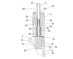
- the catheter 3 is held by the enlarged diameter portion 94 of the intra-catheter insertable portion 90, and the intra-catheter insertable portion 90 and the catheter 3 are connected in a liquid-tight state. Furthermore, the holding action of the catheter 3 is continued by the annular protrusion 53 of the connection assisting member 5, and the movement of the catheter 3 in the detaching direction is restricted. Further, in the connection state shown in FIG. 10, even when an external force in the vertical or horizontal direction is applied to the connection assisting member 5, the connection assisting member 5 is in contact with or in contact with the chemical injection member 2. There is no movement, and there is no occurrence of kinking of the catheter due to the movement of the connection assisting member 5. For this reason, a good connection state (communication state) between the catheter and the discharge port 9 of the chemical solution injection member 2 can be maintained.
- the in-vivo drug solution injector of the present invention is as follows.
- An in-vivo medicinal solution injecting device comprising a catheter and a medicinal solution injecting member for detachably attaching the catheter, wherein the medicinal solution injecting device is a cylindrical connection through which the catheter can be inserted and attached to the catheter
- the medicinal solution injecting device is a cylindrical connection through which the catheter can be inserted and attached to the catheter
- the chemical liquid injection member an injection member main body having an opening, a chemical liquid inflow space communicating with the opening, and attached to the injection member main body, communicated with the chemical liquid inflow space; and
- the discharge port has an end opening of the catheter.
- An intra-catheter insertable portion having a distal end portion having an outer diameter that can be inserted therein, and an enlarged diameter portion that is located on the injection member main body side from the distal end portion and is larger in diameter than the distal end portion.
- a cylindrical main body having an inner diameter larger than the outer diameter of the catheter; and an annular protrusion for holding a catheter provided in the cylindrical main body and having an inner diameter smaller than the outer diameter of the catheter.
- the in-vivo drug injection device wherein the annular projecting portion regulates the movement of the catheter and assists the insertion of the discharge port in the catheter into the one end of the catheter.
- the cylindrical connection assisting member has a protruding portion provided between the one end portion and the annular protruding portion, and the protruding portion is inserted into the enlarged diameter portion of the discharge port, and the diameter of the catheter is increased.
- the in-vivo drug solution injection device according to the above (1) which is capable of contacting and passing through the part.
- the in-vivo drug injection device according to (1) or (2) above, wherein the drug solution injection member can be attached to the catheter by inserting and pushing.
- (4) The in-vivo drug injection device according to any one of (1) to (3), wherein the distal end portion of the discharge port has an outer diameter smaller than an inner diameter of the catheter.
- (5) Any of the above (1) to (4), wherein the length from the one end portion of the connection auxiliary member to the annular projecting portion is longer than the length of the insertion port that can be inserted into the catheter.
- An in-vivo drug solution injector according to claim 1.
- (6) The in-vivo drug solution injection device according to any one of (1) to (5), wherein the diameter-expanded portion of the discharge port increases in a tapered shape toward the injection member main body.
- the discharge port includes a second enlarged diameter portion located on the injection member main body side from the enlarged diameter portion, and the second enlarged diameter portion is tapered toward the injection member main body side.
- the in-vivo drug solution injector according to any one of the above (1) to (6), which expands the diameter.
- the inner surface of the cylindrical connection auxiliary member is any one of the above (1) to (7), which is a reduced diameter inner surface that is tapered from the other end toward the annular projecting portion.
- In vivo drug solution injector (9) The catheter is pressed by the annular projecting portion of the cylindrical connection assisting member, and the outer diameter and inner diameter of the catheter are reduced in the pressing portion by the annular projecting portion.
- the in-vivo drug solution injector according to any one of (1) to (8) above.
Landscapes
- Health & Medical Sciences (AREA)
- Heart & Thoracic Surgery (AREA)
- Life Sciences & Earth Sciences (AREA)
- Animal Behavior & Ethology (AREA)
- Anesthesiology (AREA)
- Biomedical Technology (AREA)
- Hematology (AREA)
- Engineering & Computer Science (AREA)
- Pulmonology (AREA)
- General Health & Medical Sciences (AREA)
- Public Health (AREA)
- Veterinary Medicine (AREA)
- Biophysics (AREA)
- Gastroenterology & Hepatology (AREA)
- Infusion, Injection, And Reservoir Apparatuses (AREA)
- Media Introduction/Drainage Providing Device (AREA)
Applications Claiming Priority (2)
| Application Number | Priority Date | Filing Date | Title |
|---|---|---|---|
| JP2012074035 | 2012-03-28 | ||
| JP2012-074035 | 2012-03-28 |
Publications (1)
| Publication Number | Publication Date |
|---|---|
| WO2013146305A1 true WO2013146305A1 (fr) | 2013-10-03 |
Family
ID=49259568
Family Applications (1)
| Application Number | Title | Priority Date | Filing Date |
|---|---|---|---|
| PCT/JP2013/057240 Ceased WO2013146305A1 (fr) | 2012-03-28 | 2013-03-14 | Dispositif d'injection d'une solution médicamenteuse dans un corps |
Country Status (1)
| Country | Link |
|---|---|
| WO (1) | WO2013146305A1 (fr) |
Citations (2)
| Publication number | Priority date | Publication date | Assignee | Title |
|---|---|---|---|---|
| JP2000513952A (ja) * | 1995-05-24 | 2000-10-24 | シー・アール・バード・インコーポレーテッド | 多重型カテーテル接続装置 |
| JP2010063511A (ja) * | 2008-09-09 | 2010-03-25 | Nippon Sherwood Medical Industries Ltd | 薬液注入ポートとカテーテルの接続構造 |
-
2013
- 2013-03-14 WO PCT/JP2013/057240 patent/WO2013146305A1/fr not_active Ceased
Patent Citations (2)
| Publication number | Priority date | Publication date | Assignee | Title |
|---|---|---|---|---|
| JP2000513952A (ja) * | 1995-05-24 | 2000-10-24 | シー・アール・バード・インコーポレーテッド | 多重型カテーテル接続装置 |
| JP2010063511A (ja) * | 2008-09-09 | 2010-03-25 | Nippon Sherwood Medical Industries Ltd | 薬液注入ポートとカテーテルの接続構造 |
Similar Documents
| Publication | Publication Date | Title |
|---|---|---|
| US12311128B2 (en) | Needle and catheter insertion device | |
| EP3288631B1 (fr) | Dispositif d'accès vasculaire | |
| JP4425546B2 (ja) | 低抵抗の隔壁を有するカテーテル | |
| EP3311873A1 (fr) | Ensemble gaine | |
| WO2007092210A1 (fr) | Ensemble de perfusion | |
| JP2025123562A (ja) | 針及びカテーテルアセンブリ | |
| JPWO2018174256A1 (ja) | カテーテル組立体 | |
| JP5559524B2 (ja) | 薬液注入具 | |
| JP2006055674A (ja) | 留置針組立体 | |
| CN119258374A (zh) | 静脉留置套管 | |
| JP2021151301A (ja) | カテーテル組立体 | |
| WO2014162381A1 (fr) | Sonde à demeure et ensemble sonde | |
| JP2009201539A (ja) | 留置針装置 | |
| WO2013146305A1 (fr) | Dispositif d'injection d'une solution médicamenteuse dans un corps | |
| JP2009142492A (ja) | 留置針装置 | |
| JP6070369B2 (ja) | Yコネクタアダプタ | |
| US20210187245A1 (en) | Catheter assembly | |
| WO2013094643A1 (fr) | Dispositif implanté par voie sous-cutanée pour l'injection d'une solution de médicament | |
| JP2011120736A (ja) | 生体内挿入用カテーテルおよび薬液注入具 | |
| CN113730708B (zh) | 一种输液港装置 | |
| WO2020195352A1 (fr) | Instrument de dosage et système de dosage d'une solution médicamenteuse | |
| CN114599421B (zh) | 血管内导管装置 | |
| US8882715B2 (en) | Catheterization device and method | |
| WO2013146307A1 (fr) | Dispositif d'injection d'une solution médicamenteuse dans un corps | |
| JP2022152272A (ja) | 医療用長尺体、及び医療器具組立体 |
Legal Events
| Date | Code | Title | Description |
|---|---|---|---|
| 121 | Ep: the epo has been informed by wipo that ep was designated in this application |
Ref document number: 13768722 Country of ref document: EP Kind code of ref document: A1 |
|
| NENP | Non-entry into the national phase |
Ref country code: DE |
|
| 122 | Ep: pct application non-entry in european phase |
Ref document number: 13768722 Country of ref document: EP Kind code of ref document: A1 |
|
| NENP | Non-entry into the national phase |
Ref country code: JP |