WO2013146321A1 - Procédé de fabrication pour un instrument médical, instrument médical - Google Patents
Procédé de fabrication pour un instrument médical, instrument médical Download PDFInfo
- Publication number
- WO2013146321A1 WO2013146321A1 PCT/JP2013/057291 JP2013057291W WO2013146321A1 WO 2013146321 A1 WO2013146321 A1 WO 2013146321A1 JP 2013057291 W JP2013057291 W JP 2013057291W WO 2013146321 A1 WO2013146321 A1 WO 2013146321A1
- Authority
- WO
- WIPO (PCT)
- Prior art keywords
- hollow fiber
- point
- fiber membrane
- medical device
- manufacturing
- Prior art date
- Legal status (The legal status is an assumption and is not a legal conclusion. Google has not performed a legal analysis and makes no representation as to the accuracy of the status listed.)
- Ceased
Links
Images






Classifications
-
- A—HUMAN NECESSITIES
- A61—MEDICAL OR VETERINARY SCIENCE; HYGIENE
- A61M—DEVICES FOR INTRODUCING MEDIA INTO, OR ONTO, THE BODY; DEVICES FOR TRANSDUCING BODY MEDIA OR FOR TAKING MEDIA FROM THE BODY; DEVICES FOR PRODUCING OR ENDING SLEEP OR STUPOR
- A61M1/00—Suction or pumping devices for medical purposes; Devices for carrying-off, for treatment of, or for carrying-over, body-liquids; Drainage systems
- A61M1/14—Dialysis systems; Artificial kidneys; Blood oxygenators ; Reciprocating systems for treatment of body fluids, e.g. single needle systems for hemofiltration or pheresis
- A61M1/16—Dialysis systems; Artificial kidneys; Blood oxygenators ; Reciprocating systems for treatment of body fluids, e.g. single needle systems for hemofiltration or pheresis with membranes
- A61M1/1698—Blood oxygenators with or without heat-exchangers
-
- A—HUMAN NECESSITIES
- A61—MEDICAL OR VETERINARY SCIENCE; HYGIENE
- A61M—DEVICES FOR INTRODUCING MEDIA INTO, OR ONTO, THE BODY; DEVICES FOR TRANSDUCING BODY MEDIA OR FOR TAKING MEDIA FROM THE BODY; DEVICES FOR PRODUCING OR ENDING SLEEP OR STUPOR
- A61M1/00—Suction or pumping devices for medical purposes; Devices for carrying-off, for treatment of, or for carrying-over, body-liquids; Drainage systems
- A61M1/36—Other treatment of blood in a by-pass of the natural circulatory system, e.g. temperature adaptation, irradiation ; Extra-corporeal blood circuits
- A61M1/3621—Extra-corporeal blood circuits
- A61M1/3623—Means for actively controlling temperature of blood
-
- B—PERFORMING OPERATIONS; TRANSPORTING
- B01—PHYSICAL OR CHEMICAL PROCESSES OR APPARATUS IN GENERAL
- B01D—SEPARATION
- B01D63/00—Apparatus in general for separation processes using semi-permeable membranes
- B01D63/02—Hollow fibre modules
- B01D63/021—Manufacturing thereof
- B01D63/0231—Manufacturing thereof using supporting structures, e.g. filaments for weaving mats
-
- B—PERFORMING OPERATIONS; TRANSPORTING
- B01—PHYSICAL OR CHEMICAL PROCESSES OR APPARATUS IN GENERAL
- B01D—SEPARATION
- B01D63/00—Apparatus in general for separation processes using semi-permeable membranes
- B01D63/02—Hollow fibre modules
- B01D63/021—Manufacturing thereof
- B01D63/0232—Manufacturing thereof using hollow fibers mats as precursor, e.g. wound or pleated mats
-
- B—PERFORMING OPERATIONS; TRANSPORTING
- B01—PHYSICAL OR CHEMICAL PROCESSES OR APPARATUS IN GENERAL
- B01D—SEPARATION
- B01D63/00—Apparatus in general for separation processes using semi-permeable membranes
- B01D63/02—Hollow fibre modules
- B01D63/025—Bobbin units
-
- B—PERFORMING OPERATIONS; TRANSPORTING
- B65—CONVEYING; PACKING; STORING; HANDLING THIN OR FILAMENTARY MATERIAL
- B65H—HANDLING THIN OR FILAMENTARY MATERIAL, e.g. SHEETS, WEBS, CABLES
- B65H81/00—Methods, apparatus, or devices for covering or wrapping cores by winding webs, tapes, or filamentary material, not otherwise provided for
- B65H81/02—Covering or wrapping annular or like cores forming a closed or substantially closed figure
-
- F—MECHANICAL ENGINEERING; LIGHTING; HEATING; WEAPONS; BLASTING
- F28—HEAT EXCHANGE IN GENERAL
- F28D—HEAT-EXCHANGE APPARATUS, NOT PROVIDED FOR IN ANOTHER SUBCLASS, IN WHICH THE HEAT-EXCHANGE MEDIA DO NOT COME INTO DIRECT CONTACT
- F28D7/00—Heat-exchange apparatus having stationary tubular conduit assemblies for both heat-exchange media, the media being in contact with different sides of a conduit wall
- F28D7/10—Heat-exchange apparatus having stationary tubular conduit assemblies for both heat-exchange media, the media being in contact with different sides of a conduit wall the conduits being arranged one within the other, e.g. concentrically
- F28D7/103—Heat-exchange apparatus having stationary tubular conduit assemblies for both heat-exchange media, the media being in contact with different sides of a conduit wall the conduits being arranged one within the other, e.g. concentrically consisting of more than two coaxial conduits or modules of more than two coaxial conduits
-
- B—PERFORMING OPERATIONS; TRANSPORTING
- B01—PHYSICAL OR CHEMICAL PROCESSES OR APPARATUS IN GENERAL
- B01D—SEPARATION
- B01D2313/00—Details relating to membrane modules or apparatus
- B01D2313/22—Cooling or heating elements
- B01D2313/221—Heat exchangers
-
- B—PERFORMING OPERATIONS; TRANSPORTING
- B01—PHYSICAL OR CHEMICAL PROCESSES OR APPARATUS IN GENERAL
- B01D—SEPARATION
- B01D2323/00—Details relating to membrane preparation
- B01D2323/42—Details of membrane preparation apparatus
-
- F—MECHANICAL ENGINEERING; LIGHTING; HEATING; WEAPONS; BLASTING
- F28—HEAT EXCHANGE IN GENERAL
- F28D—HEAT-EXCHANGE APPARATUS, NOT PROVIDED FOR IN ANOTHER SUBCLASS, IN WHICH THE HEAT-EXCHANGE MEDIA DO NOT COME INTO DIRECT CONTACT
- F28D21/00—Heat-exchange apparatus not covered by any of the groups F28D1/00 - F28D20/00
- F28D2021/0019—Other heat exchangers for particular applications; Heat exchange systems not otherwise provided for
- F28D2021/005—Other heat exchangers for particular applications; Heat exchange systems not otherwise provided for for medical applications
-
- F—MECHANICAL ENGINEERING; LIGHTING; HEATING; WEAPONS; BLASTING
- F28—HEAT EXCHANGE IN GENERAL
- F28D—HEAT-EXCHANGE APPARATUS, NOT PROVIDED FOR IN ANOTHER SUBCLASS, IN WHICH THE HEAT-EXCHANGE MEDIA DO NOT COME INTO DIRECT CONTACT
- F28D21/00—Heat-exchange apparatus not covered by any of the groups F28D1/00 - F28D20/00
- F28D21/0015—Heat and mass exchangers, e.g. with permeable walls
Definitions
- the present invention relates to a method for manufacturing a medical device and a medical device.
- the oxygenator described in Patent Document 1 includes a housing, a hollow fiber membrane layer having a cylindrical shape as a whole, housed in the housing, a blood inlet and a blood outlet, a gas inlet and a gas outlet. Gas exchange between the blood and the gas through each hollow fiber membrane, that is, oxygenation and decarbonation gas are performed.
- This hollow fiber membrane layer having a cylindrical shape is formed by laminating a plurality of hollow fiber membranes, and in each layer, each hollow fiber membrane is wound around the central axis of the cylindrical body while the cylinder It reciprocates between one end side and the other end side of the body.
- Each hollow fiber membrane is wound at least once around the central axis of the cylindrical body in the forward path from one end side to the other end side, and in the return path from the other end side to the one end side, It is wound at least once around the central axis of the cylindrical body.
- Each hollow fiber membrane wound in this manner has a longer total length as the number of windings increases, and the pressure loss of the gas passing through the hollow fiber membrane increases in proportion thereto. There was a problem that. In this case, it may be difficult to perform gas exchange through each hollow fiber membrane.
- An object of the present invention is to provide a method of manufacturing a medical device that can suppress the occurrence of pressure loss when a fluid passes through a hollow fiber membrane, and a medical device manufactured by the manufacturing method. It is in.
- Such an object is achieved by the present inventions (1) to (11) below.
- (1) Manufactures a medical device having a hollow fiber membrane layer having a plurality of hollow fiber membranes, and integrating the multiple hollow fiber membranes, and a hollow fiber membrane layer obtained from a base material having a cylindrical shape as a whole.
- a way to A first step of manufacturing the base material; Cutting both ends of the base material to obtain the hollow fiber membrane layer, and a second step, In the first step, each of the hollow fiber membranes is set to a first point set at one position on one end side of the cylindrical body, and around 20 to about the central axis of the cylindrical body with respect to the first point.
- the hollow fiber membrane is passed along the circumferential direction of the cylindrical body in the forward path from the second point to the third point in order through the fifth point set at one place on one end side.
- a method for manufacturing a medical device when assuming a first line connecting the first point and the second point and a second line connecting the third point and the fourth point, respectively, the mother Cutting one end portion of the material on the other end side from the first line, and cutting the other end portion of the base material on the one end side from the second line.
- a regulating member that regulates the position of the hollow fiber membrane in the central axis direction when each hollow fiber membrane is routed from the first point to the second point.
- each hollow fiber membrane has an inner diameter of 50 to 700 ⁇ m.
- each of the hollow fiber membranes is made of porous polypropylene.
- each hollow fiber membrane in the base material to be the hollow fiber membrane layer, is reciprocated along the central axis of the cylindrical body, that is, between the first point and the fifth point. 1 turn around the central axis.
- each hollow fiber membrane has a length per one partition from the partition wall to another partition wall, for example, in the artificial lung described in Patent Document 1 (one rotation in the forward path and one rotation in the return path).
- the pressure loss can be suppressed when the fluid passes through the hollow fiber membrane.
- the folding angle becomes an acute angle at the folding point of the hollow fiber membrane, and the hollow fiber membrane does not stay there but easily shifts to the other end side.
- the folding angle of the hollow fiber membrane is made obtuse by the portion connecting the first point and the second point of the hollow fiber membrane and the portion connecting the third point and the fourth point. Thus, this positional deviation can be prevented.
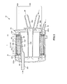
- FIG. 1 is a plan view showing an embodiment in which a medical device manufactured by the method for manufacturing a medical device of the present invention is applied to an artificial lung.
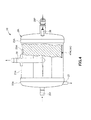
- FIG. 2 is a view of the oxygenator shown in FIG. 1 as viewed from the direction of arrow A.
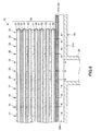
- 3 is a cross-sectional view taken along line BB in FIG.
- FIG. 4 is a view as seen from the direction of arrow C in FIG.
- FIG. 5 is a sectional view taken along line DD in FIG. 6 is a cross-sectional view taken along line EE in FIG.
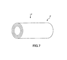
- FIG. 7 is a perspective view showing a base material that becomes a hollow fiber membrane layer included in the artificial lung shown in FIG. 1.
- FIG. 8 is a view as seen from the direction of arrow F in FIG. FIG.
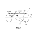
- FIG. 9 is a perspective view showing one hollow fiber membrane layer in the base material shown in FIG.
- FIG. 10 is a development view of one hollow fiber membrane layer shown in FIG.
- FIG. 11 is a cross-sectional view of one hollow fiber membrane.
- FIG. 12 is a diagram (first step diagram) sequentially illustrating steps of manufacturing the base material illustrated in FIG. 7.
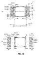
- FIG. 13 is a diagram (second process diagram) sequentially illustrating the process of cutting the base material illustrated in FIG. 7.
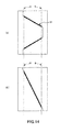
- FIG. 14 is a diagram for comparing the length per hollow fiber membrane in the oxygenator shown in FIG. 1 with the length per hollow fiber membrane in the conventional engineered lung ((a) is the former length. (B) shows the length of the latter).
- FIG. 1 is a plan view showing an embodiment when a medical device manufactured by the method for manufacturing a medical device of the present invention is applied to an oxygenator
- FIG. 2 is a view of the oxygenator shown in FIG. 3 is a cross-sectional view taken along line BB in FIG. 2
- FIG. 4 is a view seen from the direction of arrow C in FIG. 2
- FIG. 5 is a cross-sectional view taken along line DD in FIG.
- FIG. 7 is a cross-sectional view taken along line EE in FIG. 5
- FIG. 7 is a perspective view showing a base material that becomes a hollow fiber membrane layer included in the artificial lung shown in FIG. 1, and
- FIG. 9 is a perspective view showing one hollow fiber membrane layer in the base material shown in FIG. 7, FIG.
- FIG. 10 is a development view of one hollow fiber membrane layer shown in FIG.
- FIG. 12 is a cross-sectional view of one hollow fiber membrane
- FIG. 12 is a diagram sequentially illustrating the steps of manufacturing the base material shown in FIG. 7 (first step diagram)
- FIG. 14 is a diagram for comparing the length per hollow fiber membrane in the oxygenator shown in FIG. 1 with the length per hollow fiber membrane in the conventional lung (FIG. 14A). Is the former length, and (b) is the latter length).
- 1, 3, 4, and 12 are referred to as “left” or “left”, and the right side is referred to as “right” or “right”.
- 1 to 6 the inside of the oxygenator will be described as “blood inflow side” or “upstream side”, and the outside will be described as “blood outflow side” or “downstream side”.
- the artificial lung 10 shown in FIGS. 1 to 5 has an almost cylindrical shape as a whole.
- the oxygenator 10 is provided on the inner side, and is provided with a heat exchanging part 10B that exchanges heat with blood and an oxygenator part 10A that is provided on the outer peripheral side of the heat exchanging part 10B and exchanges gas with blood.
- the oxygenator 10 has a housing 2A, and an oxygenator 10A and a heat exchanger 10B are accommodated in the housing 2A.
- the housing 2A includes a cylindrical housing body 21A, a dish-shaped first lid 22A that seals the left end opening of the cylindrical housing body 21A, and a dish-shaped first lid that seals the right end opening of the cylindrical housing body 21A. 2 lids 23A.
- the cylindrical housing body 21A, the first lid body 22A, and the second lid body 23A are made of a resin material.
- the first lid body 22A and the second lid body 23A are fixed to the cylindrical housing body 21A by a method such as fusion or bonding with an adhesive.
- a tubular blood outlet port 28 is formed on the outer peripheral portion of the cylindrical housing body 21A.
- the blood outflow port 28 protrudes in a substantially tangential direction of the outer peripheral surface of the cylindrical housing body 21A (see FIG. 5).
- a tubular blood inflow port 201 and a gas outflow port 27 are formed to protrude from the first lid 22A.
- the blood inflow port 201 is formed on the end surface of the first lid 22A so that the central axis thereof is eccentric with respect to the center of the first lid 22A.
- the gas outflow port 27 is formed on the outer peripheral portion of the first lid 22A so that the central axis thereof intersects the center of the first lid 22A (see FIG. 2).
- the gas inflow port 26 is formed at the edge of the end surface of the second lid 23A.
- the heat medium inflow port 202 and the heat medium outflow port 203 are each formed at substantially the center of the end surface of the second lid 23A.
- the center lines of the heat medium inflow port 202 and the heat medium outflow port 203 are slightly inclined with respect to the center line of the second lid body 23A.
- the entire shape of the housing 2A does not necessarily have a complete columnar shape, and may be, for example, a partially missing shape or a shape with a deformed portion added.
- a cylindrical lung 10 ⁇ / b> A is housed inside the housing 2 ⁇ / b> A along the inner peripheral surface thereof.
- the artificial lung portion 10A includes a cylindrical hollow fiber membrane layer 3A and a filter member 41A as bubble removing means 4A provided on the outer peripheral side (blood outflow portion side) of the hollow fiber membrane layer 3A.
- the hollow fiber membrane layer 3A and the filter member 41A are arranged in the order of the hollow fiber membrane layer 3A and the filter member 41A from the blood inflow side.
- the hollow fiber membrane layer 3A is composed of a large number of hollow fiber membranes 31 having a gas exchange function, and these hollow fiber membranes 31 are integrated. As will be described later, the hollow fiber membrane layer 3A is obtained from a base material 3 'having a cylindrical shape as a whole.
- the maximum outer diameter ⁇ D max of the hollow fiber membrane layer 3A (base material 3 ′) is preferably 20 to 200 mm, and more preferably 40 to 150 mm (see FIG. 5). Further, the length L along the central axis direction of the hollow fiber membrane layer 3A is preferably 30 to 250 mm, more preferably 50 to 200 mm (see FIG. 3). When the hollow fiber membrane layer 3A has such conditions, the hollow fiber membrane layer 3A has an excellent gas exchange function.
- each hollow fiber membrane 31 is preferably 50 to 700 ⁇ m, and more preferably 70 to 600 ⁇ m (see FIG. 11).
- the outer diameter ⁇ d 2 of each hollow fiber membrane 31 is preferably 100 to 900 ⁇ m, and more preferably 120 to 800 ⁇ m (see FIG. 11).
- the inner diameter .phi.d 1 and the ratio d 1 / d 2 between the outer diameter .phi.d 2 is preferably there 0.5-0.9, more preferably 0.6-0.8.
- the pressure loss when the gas flows through the lumen (flow path 32) of the hollow fiber membrane 31 can be made relatively small while maintaining its own strength.
- the thickness of the hollow fiber membrane 31 becomes thin, and the strength is lowered depending on other conditions.
- the inner diameter ⁇ d 1 is smaller than the lower limit value, the pressure loss when the gas flows into the lumen of the hollow fiber membrane 31 increases depending on other conditions.
- the distance of the hollow fiber membranes 31 and adjacent and more preferably of 1/10 ⁇ 1/1 ⁇ d 2.
- the method for producing such a hollow fiber membrane 31 is not particularly limited. For example, by using a stretching method or a solid-liquid phase separation method or the like, by appropriately adjusting conditions such as a spinning speed and a resin discharge amount, a predetermined method can be obtained.
- the hollow fiber membrane 31 having the inner diameter ⁇ d 1 and the outer diameter ⁇ d 2 can be manufactured.
- each hollow fiber membrane 31 for example, a hydrophobic polymer material such as polypropylene, polyethylene, polysulfone, polyacrylonitrile, polytetrafluoroethylene, polymethylpentene, etc. is used, preferably a polyolefin resin, More preferably, it is polypropylene.
- the hollow fiber membrane 31 is more preferably one in which micropores are formed in the wall portion by a stretching method or a solid-liquid phase separation method, that is, one made of porous polypropylene is more preferred. Thereby, gas exchange is reliably performed between the blood and the hollow fiber membrane 31.
- each hollow fiber membrane 31 that is, the left end (one end) and the right end (the other end) are fixed to the inner surface of the cylindrical housing body 21A by partition walls 8 and 9, respectively.
- the partition walls 8 and 9 are made of, for example, a potting material such as polyurethane or silicone rubber, an adhesive, or the like.
- the hollow fiber membrane layer 3A is filled between the cylindrical housing main body 21A and the heat exchanging portion 10B with almost no gap, so that the hollow fiber membrane layer 3A has a substantially cylindrical shape as a whole. There is no. Thereby, the high filling efficiency of the hollow fiber membrane 31 is obtained with respect to the cylindrical housing body 21A having the same shape (the dead space is small), which contributes to the miniaturization and high performance of the oxygenator 10A.
- the blood inflow port 201 serves as a blood inflow part of the blood flowing in from the blood inflow port 201.
- a blood inflow side space 24 ⁇ / b> A communicating with is formed (see FIGS. 3 and 5).
- the blood inflow side space 24A includes a first cylindrical member 241 having a cylindrical shape, and a plate piece 242 that is disposed inside the first cylindrical member 241 and is opposed to a part of the inner peripheral portion thereof. It is a defined space. Then, the blood that has flowed into the blood inflow side space 24 ⁇ / b> A can flow down over the entire blood flow path 33 through the plurality of side holes 243 formed in the first cylindrical member 241.
- a cylindrical gap is formed between the outer peripheral surface of the filter member 41A and the inner peripheral surface of the cylindrical housing body 21A, and this gap forms a blood outflow side space 25A.
- the blood outflow portion is constituted by the blood outflow side space 25A and the blood outflow port 28 communicating with the blood outflow side space 25A. Since the blood outflow part has the blood outflow side space 25A, a space where the blood that has passed through the filter member 41A flows toward the blood outflow port 28 is secured, and the blood can be smoothly discharged.
- the hollow fiber membrane layer 3A, the filter member 41A, and the blood channel 33 are present between the blood inflow side space 24A and the blood outflow side space 25A.
- bubble removing means 4A having a function of removing bubbles from blood while capturing bubbles in the blood is installed.
- This bubble removing means 4A has a filter member 41A.
- the filter member 41 ⁇ / b> A has a function of capturing bubbles present in the blood flowing through the blood flow path 33.
- the filter member 41A is composed of a substantially rectangular sheet-like member (hereinafter also simply referred to as “sheet”), and is formed by winding the sheet into a cylindrical shape.
- the filter member 41A is fixed to the housing 2A by fixing both ends thereof with partition walls 8 and 9, respectively (see FIG. 3).
- the inner peripheral surface of the filter member 41A is provided in contact with the downstream surface (blood outflow portion side) of the hollow fiber membrane layer 3A and covers almost the entire surface.
- the filter member 41A can capture the air bubbles (see FIG. 6). Further, the air bubbles captured by the filter member 41A are pushed into the hollow fiber membranes 31 in the vicinity of the filter member 41A by the blood flow and are removed from the blood flow path 33 as a result.
- an annular rib 291 is formed to protrude inside the first lid 22 ⁇ / b> A.
- a first chamber 221a is defined by the first lid 22A, the rib 291 and the partition wall 8.
- the first chamber 221a is a gas outflow chamber from which gas flows out.
- the left end opening of each hollow fiber membrane 31 is open to and communicates with the first chamber 221a.
- annular rib 292 is also formed to protrude inside the second lid 23A.
- a second chamber 231 a is defined by the second lid body 23 ⁇ / b> A, the rib 292, and the partition wall 9.
- the second chamber 231a is a gas inflow chamber into which gas flows.
- the right end opening of each hollow fiber membrane 31 is open to and communicated with the second chamber 231a.
- each hollow fiber membrane 31 constitutes a flow path 32 (gas flow path) through which gas flows.
- the gas inflow port 26 and the second chamber 231a constitute a gas inflow portion located upstream of the flow path 32, and the gas outflow port 27 and the first chamber 221a constitute a gas located downstream of the flow path 32.
- An outflow section is constructed.
- the heat exchange unit 10B is installed inside the artificial lung unit 10A.
- the heat exchange part 10B has a hollow fiber membrane layer 3B.
- the hollow fiber membrane layer 3B is the same as the hollow fiber membrane layer 3A except that it has a function of performing heat exchange. That is, the hollow fiber membrane layer 3B having a function of performing heat exchange is also configured by a large number of hollow fiber membranes 31 in the same manner as the hollow fiber membrane layer 3A of the artificial lung portion 10A, and these hollow fiber membranes 31 are integrated. The gap between the hollow fiber membranes 31 becomes the blood flow path 33.
- the hollow fiber membrane layer 3B is also obtained from a base material 3 'having a cylindrical shape as a whole.
- the hollow fiber membrane layer 3B will be described mainly with respect to the differences from the hollow fiber membrane layer 3A described above, and description of the same matters will be omitted.
- both ends of the hollow fiber membrane layer 3B are formed on the inner surface of the cylindrical housing main body 21A by the partition walls 8 and 9, respectively. It is fixed against. Furthermore, the hollow fiber membrane layer 3 ⁇ / b> B has an inner peripheral portion engaged with an uneven portion 244 formed on the outer peripheral portion of the first cylindrical member 241. By this engagement and fixing by the partition walls 8 and 9, the hollow fiber membrane layer 3B is securely fixed to the cylindrical housing main body 21A, and thus the positional displacement of the hollow fiber membrane layer 3B occurs during use of the artificial lung 10. Can be reliably prevented.
- a second cylindrical member 245 disposed concentrically with the first cylindrical member 241 is disposed inside the first cylindrical member 241.
- the heat medium for example, water
- the heat medium inflow port 202 flows through the hollow fiber membranes 31 of the hollow fiber membrane layer 3 ⁇ / b> B on the outer peripheral side of the first cylindrical member 241.
- heat exchange heat exchange (heating or cooling) is performed with the blood in contact with the hollow fiber membrane 31.
- the heat exchanging part 10B is installed inside the artificial lung part 10A as described above, the following effects are produced. That is, first, the oxygenator 10A and the heat exchanger 10B can be efficiently accommodated in one housing 2A, and the dead space is small. Therefore, efficient gas exchange is performed with the small oxygenator 10. be able to. Second, the oxygenator 10A and the heat exchanger 10B are close to each other, and the blood exchanged in the heat exchanger 10B is prevented from radiating or absorbing heat as much as possible, while the oxygenator 10A. Can flow in quickly.
- the hollow fiber membrane 31 constituting the heat exchange part 10B in addition to those mentioned as the constituent material of the hollow fiber membrane 31 constituting the artificial lung part 10A described above, for example, polyethylene terephthalate, polycarbonate, polyurethane, nylon Polystyrene, vinyl chloride can be used.
- blood flowing from the blood inflow port 201 sequentially passes through the blood inflow side space 24A and the side hole 243, and flows into the heat exchange unit 10B.
- the blood flows in the blood flow path 33 in the downstream direction, and contacts the surface of each hollow fiber membrane 31 to exchange heat (warming or cooling). The blood thus heat-exchanged flows into the oxygenator 10A.
- the oxygenator 10A blood flows in the downstream direction through the blood channel 33.
- the gas (gas containing oxygen) supplied from the gas inflow port 26 is distributed from the second chamber 231a to the flow path 32 of each hollow fiber membrane 31, and after flowing through the flow path 32, the first The gas is accumulated in the room 221a and discharged from the gas outflow port 27.
- the blood flowing through the blood flow path 33 contacts the surface of each hollow fiber membrane 31, and gas exchange (oxygenation, decarboxylation gas) is performed with the gas flowing through the flow path 32.
- the blood from which gas has been exchanged and bubbles have been removed as described above flows out from the blood outflow port 28.
- the artificial lung 10 as a medical instrument provided with the hollow fiber membrane layers 3A and 3B is manufactured by the method for manufacturing a medical instrument of the present invention. Next, this manufacturing method will be described.
- This manufacturing method includes a first step of manufacturing the base material 3 ′ of the hollow fiber membrane layer 3A (the same applies to the hollow fiber membrane layer 3B), and cutting both ends of the base material 3 ′ to obtain a hollow fiber membrane. It has the 2nd process of obtaining layer 3A, and the 3rd process which stores and assembles hollow fiber membrane layer 3A etc. in order in housing 2A.
- the base material 3 ' is formed by laminating a large number of hollow fiber membranes 31, and the number of layers is not particularly limited, but for example, 3 to 40 layers are preferable.
- the number of layers is not particularly limited, but for example, 3 to 40 layers are preferable.
- three (hollow fiber membranes 31a, 31b, 31c) of the multiple hollow fiber membranes 31 in the innermost layer located on the innermost side are representatively drawn.
- the hollow fiber membrane 31a among the hollow fiber membranes 31a to 31c is representatively drawn.
- a device including a rotating device 80 and a winder device 90 is used (see FIG. 12).
- the rotating device 80 is connected to a motor 801, a motor shaft 802 that is connected to the motor 801, is rotated by the operation of the motor 801, and is fixed to the left end portion of the motor shaft 802, and a cylindrical core member around which the hollow fiber membrane 31 is wound.
- 100 has a support member 803 that is detachably mounted.
- the rotating device 80 has rod-shaped regulating members 804a and 804b that temporarily regulate the position of the hollow fiber membrane 31 that is supplied from the winder device 90 and wound around the core member 100.
- the restriction member 804 is in a positional relationship perpendicular to the central axis 106 of the core member 100 attached to the support member 803. Further, the regulating members 804 a and 804 b are supported so as to be able to approach and separate from each other along the direction of the central axis 106 of the core member 100.
- the winder device 90 is supported by the main body 901, the main body 901 so as to be reciprocable in the left-right direction (horizontal direction), and supplies the hollow fiber membrane 31 to the core member 100.
- the hollow member 31 is rotated from the winder device 90 to one (or a plurality of) the core member 100 while the core member 100 is rotated by the rotating device 80. Supply.
- the hollow fiber membrane 31 is It is wound in a direction inclined with respect to the central axis of the core member 100, that is, spirally wound or in a direction perpendicular to the central axis of the core member 100 (see FIG. 12).
- the first cylindrical member 241 can be used instead of the core member 100.
- an apparatus having a cutter 701 is used as the cutting apparatus 70 for cutting the base material 3 '(see FIG. 13A).
- the cutting device 70 is fixed, and the base material 3 ′ is cut by bringing the base material 3 ′ close to the cutter 701.
- the cutting device 70 is not limited to the configuration having the cutter 701, and may be, for example, a configuration that ejects a water jet or a configuration that irradiates laser light.
- the manufacturing method includes the first step, the second step, the third step, and the fourth step. Each step will be described in order.
- the core member 100 around which the hollow fiber membranes 31 constituting the base material 3 ′ are wound has a cylindrical shape, like the base material 3 ′. And in a 1st process, five points are set on the outer periphery of the core member 100, and each hollow fiber membrane 31 will go through the said five points in order, respectively (FIG. 8, FIG. 9, FIG. 10, (See FIG. 12).
- the first point 101 is set at one place on the left end side (one end side) of the core member 100.
- the second point 102 is set at one position that is shifted from the first point 101 by an angle ⁇ around the central axis 106 of the core member 100.
- the angle ⁇ is not particularly limited, and is preferably 20 to 175 °, and more preferably 30 to 150 °, for example.
- the third point 103 is set on the right end side (the other end side) of the core member 100 at one place on the substantially opposite side of the first point 101 via the central axis 106. Therefore, the first point 101 and the third point 103 are in a substantially symmetrical positional relationship (point symmetry) around the center when the central portion in the longitudinal direction of the central axis 106 is the center of symmetry.
- the fourth point 104 is set at one place on the right end side of the core member 100 at a position substantially opposite to the second point 102 via the central axis 106.
- the second point 102 and the fourth point 104 have a substantially symmetrical positional relationship (point symmetry) around the center when the central portion in the longitudinal direction of the central axis 106 is the center of symmetry.
- the fifth point 105 is set at substantially the same location as the first point 101.
- the fifth point 105 may be set at one place on the left end side of the first point 101 on the outer periphery of the core member 100.
- substantially means that, for example, as shown in FIG. 12E, the fifth point 105 is adjacent to the first point 101 without overlapping.
- the hollow fiber membrane 31 is wound around the core member 100 in which the first point 101 to the fifth point 105 are set using the winding device 60 including the rotating device 80 and the winder device 90.
- the rotation device 80 includes a regulating member 804a and the regulating member 804b is spaced at a pitch p 1. Further, the regulating member 804a is in contact with the core member 100 at substantially the same position as the first point 101 in the direction of the central axis 106.
- the guide unit 902 is located on the leftmost side in FIG. This position is on the left side of the regulating member 804a in the direction of the central axis 106.
- One end of the hollow fiber membrane 31a pulled out from the winder device 90 is held at the first point 101 and is engaged with the regulating member 804a.
- the position of the hollow fiber membrane 31a in the direction of the central axis 106 is regulated by the regulating member 804a. It is surely wound up to the point 102. Thereafter, the guide unit 902 of the winder device 90 moves to the right as shown in FIG. The operation of the motor 801 is continued until the hollow fiber membrane 31a reaches the first point 101 to the fifth point 105.
- the hollow fiber membrane 31a engages with the regulating member 804b.
- the hollow fiber membrane 31a extends from the second point 102 to the third point 103 at the shortest distance while being spirally wound along the circumferential direction of the core member 100.
- shaft 106 direction is controlled by the control member 804b.
- the hollow fiber membrane 31a is reliably wound from the 3rd point 103 to the 4th point 104 (refer FIG.12 (d)).
- the hollow fiber membrane 31a engages with the regulating member 804a again.
- the hollow fiber membrane 31a reaches from the fourth point 104 to the fifth point 105 at the shortest distance while being spirally wound along the circumferential direction of the core member 100.
- the restricting member 804a and the restricting member 804b at this time are separated from each other by a pitch p 2 (> pitch p 1 ).
- a conventional artificial lung has a hollow fiber membrane layer in which a large number of hollow fiber membranes are laminated, and has a cylindrical shape as a whole.
- one hollow fiber membrane is a cylindrical body.
- the first point and the second point are the same point
- the third point and the fourth point are the same point.
- each hollow fiber membrane is wound at least once around the central axis of the cylindrical body in the outward path from the one end side to the other end side of the cylindrical body.
- Each hollow fiber membrane wound in this way has a longer overall length as the number of windings increases, and the pressure loss of the gas passing through the hollow fiber membrane increases in proportion thereto. Resulting in.
- the wound hollow fiber membrane 31 reciprocates the core member 100, that is, during the period from the first point 101 to the fifth point 105. In addition, it is only wound once around the central axis 106 (see FIG. 9). As a result, as shown in FIG. 14, the hollow fiber membrane 31 has a length per partition from the partition wall 8 to the other partition wall 9 (see FIG. 14 (a)). This is shorter than the length per membrane (see FIG. 14B), and as a result, when gas passes through the hollow fiber membrane 31, pressure loss can be suppressed as compared with the prior art.
- the folding angle becomes an acute angle at the folding point of the hollow fiber membrane 31, and the hollow fiber membrane 31 does not stay there but easily shifts to the other end side.
- the hollow fiber membrane 31 has a portion connecting the first point 101 and the second point 102 and a portion connecting the third point 103 and the fourth point 104 of the hollow fiber membrane 31. This misalignment can be prevented by making the folding angle obtuse.
- the hollow fiber membranes 31b and 31c can be further wound similarly to the hollow fiber membrane 31a.
- the first point 101 (fifth point 105) and the second point 102 through which the hollow fiber membrane 31b passes are respectively the first point 101 (fifth point 105) and the second point through which the hollow fiber membrane 31a passes.
- the third point 103 and the fourth point 104 through which the hollow fiber membrane 31b passes are located on the left side from the 102, and are located at the right side from the third point 103 and the fourth point 104 through which the hollow fiber membrane 31a passes, respectively. (See FIG. 8).
- first point 101 (fifth point 105) and the second point 102 through which the hollow fiber membrane 31c passes are respectively the first point 101 (fifth point 105) and the second point 102 through which the hollow fiber membrane 31b passes.
- the third point 103 and the fourth point 104 through which the hollow fiber membrane 31c passes are located on the right side of the third point 103 and the fourth point 104 through which the hollow fiber membrane 31b passes, respectively. (See FIG. 8).
- the layer formed of the hollow fiber membrane 31 can be laminated on the innermost layer with the layer formed of the hollow fiber membrane 31 being the innermost layer.
- the base material 3 ′ is obtained through the first step as described above.
- each hollow fiber membrane 31 is fixed with the potting material 50 in the both ends of base material 3 '.
- the potting material 50 becomes the partition walls 8 and 9.
- the base material 3 ′ before being fixed with the potting material is accommodated in the housing.
- liquid polyurethane which is a constituent material of the potting material, is injected into the housing.
- the whole housing is centrifuged, and then the liquid polyurethane is dried.
- the both ends of base material 3 ' will be in the state fixed with the potting material. And this base material 3 'is taken out from a housing.
- the hollow fiber membrane 31 located on the innermost side in the plan view among the multiple hollow fiber membranes 31 (in the configuration shown in FIG. 13 (a), the hollow fiber
- the first line (first imaginary line) 341 connecting the first point 101 and the second point 102 of the film 31a) and the second line (second line) connecting the third point 103 and the fourth point 104 Imaginary line) 342 is assumed.
- a portion on the right end side of the first line 341 at the left end portion of the base material 3 ′ is defined as a first cutting line 351
- a portion on the left end side of the second line 342 at the right end portion of the base material 3 ′ is defined.
- a second cutting line 352 is assumed.
- first cutting line 351 is preferably set at a position 0.5 to 20 mm away from the first line 341.
- the second cutting line 352 is also preferably set at a position 0.5 to 20 mm away from the second line 342.
- the cutting device 70 is used to cut the first cutting line 351 and the second cutting line 352, respectively.
- the base material 3 ′ is divided into three members, and the member located at the center becomes the hollow fiber membrane layer 3A.
- the members at both ends are discarded.
- the hollow fiber membrane layer 3A is obtained through the second step as described above.
- the filter member 41A is wound around the hollow fiber membrane layer 3B, and then substantially the same as the fixing method using the potting material 50 in the first step.
- the fixing is done by taking a method.
- this artificial lung 10 it is possible to suppress the occurrence of pressure loss when gas passes through the hollow fiber membrane 31 of the hollow fiber membrane layer 3A. Thereby, gas exchange via each hollow fiber membrane 31 can be performed easily and reliably. Further, in the hollow fiber membrane layer 3A, so-called blood short-circuiting can be suppressed or prevented.
- each hollow fiber membrane constituting the hollow fiber membrane layer of the artificial lung part and each hollow fiber membrane constituting the hollow fiber membrane layer of the heat exchange part were the same in the above embodiment,
- one (the former) hollow fiber membrane may be thinner than the other (the latter) hollow fiber membrane, or both hollow fiber membranes may be made of different materials.
- a hollow fiber membrane layer (second hollow fiber membrane layer) having the same function as that of the hollow fiber membrane layer of the artificial lung part, that is, a gas exchange function, is disposed inside the heat exchange part. Good.
- the heat exchanging portion is provided with the hollow fiber membrane layer having a heat exchanging function, but is not limited thereto, and may be provided with a so-called bellows type heat exchanging body.
- This exchanger can be composed of, for example, a metal material such as stainless steel or aluminum, or a resin material such as polyethylene or polycarbonate.
- the route through which each hollow fiber membrane sequentially passes from the first point to the fifth point may be repeated a plurality of times. Thereby, the continuous winding of each hollow fiber membrane can be performed, and thus the production efficiency of the base material is improved.
- the method for producing a medical device of the present invention comprises a hollow fiber membrane obtained from a base material having a plurality of hollow fiber membranes, and accumulating the multiple hollow fiber membranes to form a cylindrical shape as a whole.
- a method of manufacturing a medical device including a layer comprising: a first step of manufacturing the base material; and a second step of obtaining both the hollow fiber membrane layers by cutting both ends of the base material.
- each of the hollow fiber membranes has a first point set at one position on one end side of the cylindrical body, and a central axis of the cylindrical body with respect to the first point.
- the hollow fiber membrane is passed from the second point to the third point in order by passing through a point and a fifth point that is substantially the same as the first point or set at one place on one end side of the first point.
- the cylinder is wound along the circumferential direction of the cylindrical body, and reaches the third point from the second point at the shortest distance.
Landscapes
- Health & Medical Sciences (AREA)
- Engineering & Computer Science (AREA)
- Heart & Thoracic Surgery (AREA)
- Chemical & Material Sciences (AREA)
- Chemical Kinetics & Catalysis (AREA)
- Vascular Medicine (AREA)
- Urology & Nephrology (AREA)
- Emergency Medicine (AREA)
- Animal Behavior & Ethology (AREA)
- Veterinary Medicine (AREA)
- Hematology (AREA)
- Life Sciences & Earth Sciences (AREA)
- Anesthesiology (AREA)
- General Health & Medical Sciences (AREA)
- Public Health (AREA)
- Biomedical Technology (AREA)
- Manufacturing & Machinery (AREA)
- Physics & Mathematics (AREA)
- Thermal Sciences (AREA)
- Mechanical Engineering (AREA)
- General Engineering & Computer Science (AREA)
- Cardiology (AREA)
- External Artificial Organs (AREA)
- Separation Using Semi-Permeable Membranes (AREA)
Priority Applications (3)
| Application Number | Priority Date | Filing Date | Title |
|---|---|---|---|
| JP2014507678A JP6396795B2 (ja) | 2012-03-26 | 2013-03-14 | 医療器具の製造方法 |
| EP13770190.0A EP2832387B1 (fr) | 2012-03-26 | 2013-03-14 | Procédé de fabrication pour un instrument médical, instrument médical |
| US14/495,179 US9867919B2 (en) | 2012-03-26 | 2014-09-24 | Production method for medical instrument and medical instrument |
Applications Claiming Priority (2)
| Application Number | Priority Date | Filing Date | Title |
|---|---|---|---|
| JP2012070139 | 2012-03-26 | ||
| JP2012-070139 | 2012-03-26 |
Related Child Applications (1)
| Application Number | Title | Priority Date | Filing Date |
|---|---|---|---|
| US14/495,179 Continuation US9867919B2 (en) | 2012-03-26 | 2014-09-24 | Production method for medical instrument and medical instrument |
Publications (1)
| Publication Number | Publication Date |
|---|---|
| WO2013146321A1 true WO2013146321A1 (fr) | 2013-10-03 |
Family
ID=49259585
Family Applications (1)
| Application Number | Title | Priority Date | Filing Date |
|---|---|---|---|
| PCT/JP2013/057291 Ceased WO2013146321A1 (fr) | 2012-03-26 | 2013-03-14 | Procédé de fabrication pour un instrument médical, instrument médical |
Country Status (4)
| Country | Link |
|---|---|
| US (1) | US9867919B2 (fr) |
| EP (1) | EP2832387B1 (fr) |
| JP (1) | JP6396795B2 (fr) |
| WO (1) | WO2013146321A1 (fr) |
Cited By (6)
| Publication number | Priority date | Publication date | Assignee | Title |
|---|---|---|---|---|
| WO2015115138A1 (fr) * | 2014-01-31 | 2015-08-06 | テルモ株式会社 | Procédé de fabrication d'échangeur de chaleur, et échangeur de chaleur |
| WO2016009780A1 (fr) * | 2014-07-15 | 2016-01-21 | テルモ株式会社 | Procédé de production de faisceaux de membranes à fibres creuses et procédé de production de poumon artificiel |
| WO2016021321A1 (fr) * | 2014-08-06 | 2016-02-11 | テルモ株式会社 | Faisceau de membranes à fibres creuses ainsi que procédé de fabrication de celui-ci, et poumon artificiel |
| WO2016021322A1 (fr) * | 2014-08-06 | 2016-02-11 | テルモ株式会社 | Procédé de fabrication de faisceau de membranes à fibres creuses |
| WO2016136711A1 (fr) * | 2015-02-24 | 2016-09-01 | テルモ株式会社 | Procédé de fabrication d'un dispositif de traitement du sang du type à fibres creuses, et dispositif de traitement du sang du type à fibres creuses |
| JPWO2018043287A1 (ja) * | 2016-08-31 | 2019-06-24 | テルモ株式会社 | 熱交換器、人工肺および熱交換器の製造方法 |
Families Citing this family (2)
| Publication number | Priority date | Publication date | Assignee | Title |
|---|---|---|---|---|
| JP6962820B2 (ja) | 2015-12-14 | 2021-11-05 | テルモ株式会社 | 着脱式圧力センサおよび着脱式圧力センサを備える体外循環装置 |
| WO2018062271A1 (fr) * | 2016-09-30 | 2018-04-05 | テルモ株式会社 | Procédé de production de stratifié de couche de film en fibre creuse, et stratifié de couche de film en fibre creuse |
Citations (3)
| Publication number | Priority date | Publication date | Assignee | Title |
|---|---|---|---|---|
| JPH0536088B2 (fr) * | 1984-03-23 | 1993-05-28 | Baxter Int | |
| JPH05214608A (ja) * | 1991-09-04 | 1993-08-24 | Akzo Nv | 中空糸巻体を製造する方法 |
| JP4041254B2 (ja) | 1999-12-15 | 2008-01-30 | テルモ株式会社 | 中空糸膜型人工肺 |
Family Cites Families (7)
| Publication number | Priority date | Publication date | Assignee | Title |
|---|---|---|---|---|
| BE793624A (fr) * | 1972-01-10 | 1973-05-02 | Baxter Laboratories Inc | Dispositif pour le transfert de masses, presentant une membrane de diffision tubulaire enroulee |
| US4336138A (en) * | 1975-07-26 | 1982-06-22 | Toyobo Co., Ltd. | Permeation separation apparatus |
| DE2542438C3 (de) * | 1975-09-24 | 1981-01-22 | Dr. Eduard Fresenius Chemisch-Pharmazeutische Industrie Kg Apparatebau Kg, 6380 Bad Homburg | Dialysator |
| JPS6037029B2 (ja) * | 1978-01-10 | 1985-08-23 | 東洋紡績株式会社 | 流体分離用糸条パツケ−ジの製造法 |
| US5299749A (en) * | 1992-03-24 | 1994-04-05 | Air Products And Chemicals, Inc. | Method of winding hollow fiber membranes |
| US6004511A (en) * | 1995-09-01 | 1999-12-21 | Baxter International Inc. | Hollow fiber oxygenator |
| US6273355B1 (en) * | 1999-05-06 | 2001-08-14 | Dideco S.P.A. | Method and apparatus for manufacturing wound tube bundles |
-
2013
- 2013-03-14 EP EP13770190.0A patent/EP2832387B1/fr active Active
- 2013-03-14 WO PCT/JP2013/057291 patent/WO2013146321A1/fr not_active Ceased
- 2013-03-14 JP JP2014507678A patent/JP6396795B2/ja active Active
-
2014
- 2014-09-24 US US14/495,179 patent/US9867919B2/en active Active
Patent Citations (3)
| Publication number | Priority date | Publication date | Assignee | Title |
|---|---|---|---|---|
| JPH0536088B2 (fr) * | 1984-03-23 | 1993-05-28 | Baxter Int | |
| JPH05214608A (ja) * | 1991-09-04 | 1993-08-24 | Akzo Nv | 中空糸巻体を製造する方法 |
| JP4041254B2 (ja) | 1999-12-15 | 2008-01-30 | テルモ株式会社 | 中空糸膜型人工肺 |
Cited By (16)
| Publication number | Priority date | Publication date | Assignee | Title |
|---|---|---|---|---|
| JPWO2015115138A1 (ja) * | 2014-01-31 | 2017-03-23 | テルモ株式会社 | 熱交換器の製造方法および熱交換器 |
| CN105916534B (zh) * | 2014-01-31 | 2020-07-24 | 泰尔茂株式会社 | 换热器的制造方法及换热器 |
| EP3100751A4 (fr) * | 2014-01-31 | 2017-10-25 | Terumo Kabushiki Kaisha | Procédé de fabrication d'échangeur de chaleur, et échangeur de chaleur |
| CN105916534A (zh) * | 2014-01-31 | 2016-08-31 | 泰尔茂株式会社 | 换热器的制造方法及换热器 |
| WO2015115138A1 (fr) * | 2014-01-31 | 2015-08-06 | テルモ株式会社 | Procédé de fabrication d'échangeur de chaleur, et échangeur de chaleur |
| WO2016009780A1 (fr) * | 2014-07-15 | 2016-01-21 | テルモ株式会社 | Procédé de production de faisceaux de membranes à fibres creuses et procédé de production de poumon artificiel |
| JPWO2016021321A1 (ja) * | 2014-08-06 | 2017-05-18 | テルモ株式会社 | 中空糸膜束、人工肺および中空糸膜束の製造方法 |
| CN106573096A (zh) * | 2014-08-06 | 2017-04-19 | 泰尔茂株式会社 | 中空纤维膜束、人工肺及中空纤维膜束的制造方法 |
| JPWO2016021322A1 (ja) * | 2014-08-06 | 2017-05-25 | テルモ株式会社 | 中空糸膜束の製造方法 |
| WO2016021322A1 (fr) * | 2014-08-06 | 2016-02-11 | テルモ株式会社 | Procédé de fabrication de faisceau de membranes à fibres creuses |
| WO2016021321A1 (fr) * | 2014-08-06 | 2016-02-11 | テルモ株式会社 | Faisceau de membranes à fibres creuses ainsi que procédé de fabrication de celui-ci, et poumon artificiel |
| CN106573096B (zh) * | 2014-08-06 | 2022-05-24 | 泰尔茂株式会社 | 中空纤维膜束、人工肺及中空纤维膜束的制造方法 |
| WO2016136711A1 (fr) * | 2015-02-24 | 2016-09-01 | テルモ株式会社 | Procédé de fabrication d'un dispositif de traitement du sang du type à fibres creuses, et dispositif de traitement du sang du type à fibres creuses |
| CN107249664A (zh) * | 2015-02-24 | 2017-10-13 | 泰尔茂株式会社 | 中空纤维型血液处理装置的制造方法及中空纤维型血液处理装置 |
| JPWO2016136711A1 (ja) * | 2015-02-24 | 2017-11-30 | テルモ株式会社 | 中空糸型血液処理装置の製造方法および中空糸型血液処理装置 |
| JPWO2018043287A1 (ja) * | 2016-08-31 | 2019-06-24 | テルモ株式会社 | 熱交換器、人工肺および熱交換器の製造方法 |
Also Published As
| Publication number | Publication date |
|---|---|
| EP2832387A1 (fr) | 2015-02-04 |
| US20150010433A1 (en) | 2015-01-08 |
| EP2832387B1 (fr) | 2020-10-07 |
| JP6396795B2 (ja) | 2018-09-26 |
| EP2832387A4 (fr) | 2015-11-18 |
| JPWO2013146321A1 (ja) | 2015-12-10 |
| US9867919B2 (en) | 2018-01-16 |
Similar Documents
| Publication | Publication Date | Title |
|---|---|---|
| JP6396795B2 (ja) | 医療器具の製造方法 | |
| JP4795536B2 (ja) | チューブ状バンドルのハウジングへのポッティング | |
| JP5890827B2 (ja) | 人工肺 | |
| JP6526576B2 (ja) | 熱交換器の製造方法 | |
| CN109689125B (zh) | 中空纤维膜层层合体的制造方法及中空纤维膜层层合体 | |
| US9050564B2 (en) | Filter module and system having spirally wound membrane filters, and method for the production thereof | |
| WO2018139334A1 (fr) | Échangeur de chaleur, et poumons artificiels | |
| JP6109150B2 (ja) | 医療器具 | |
| EP3082899B1 (fr) | Échangeur de chaleur et oxygénateur radiaux partiels | |
| US11534536B2 (en) | Heat exchanger and oxygenator | |
| WO2016009780A1 (fr) | Procédé de production de faisceaux de membranes à fibres creuses et procédé de production de poumon artificiel | |
| EP3508233B1 (fr) | Échangeur de chaleur, poumon artificiel, et procédé de fabrication d'échangeur de chaleur | |
| CN102895880A (zh) | 卷绕式膜蒸馏组件及膜蒸馏方法 | |
| WO2015008327A1 (fr) | Poumon artificiel | |
| JP5644393B2 (ja) | 中空糸膜シートの製造方法、中空糸膜モジュールの製造方法 |
Legal Events
| Date | Code | Title | Description |
|---|---|---|---|
| 121 | Ep: the epo has been informed by wipo that ep was designated in this application |
Ref document number: 13770190 Country of ref document: EP Kind code of ref document: A1 |
|
| ENP | Entry into the national phase |
Ref document number: 2014507678 Country of ref document: JP Kind code of ref document: A |
|
| WWE | Wipo information: entry into national phase |
Ref document number: 2013770190 Country of ref document: EP |
|
| NENP | Non-entry into the national phase |
Ref country code: DE |