WO2013146464A1 - Matériau d'électrode, ainsi que condensateur et batterie rechargeable qui utilisent ledit matériau d'électrode - Google Patents
Matériau d'électrode, ainsi que condensateur et batterie rechargeable qui utilisent ledit matériau d'électrode Download PDFInfo
- Publication number
- WO2013146464A1 WO2013146464A1 PCT/JP2013/057803 JP2013057803W WO2013146464A1 WO 2013146464 A1 WO2013146464 A1 WO 2013146464A1 JP 2013057803 W JP2013057803 W JP 2013057803W WO 2013146464 A1 WO2013146464 A1 WO 2013146464A1
- Authority
- WO
- WIPO (PCT)
- Prior art keywords
- electrode
- negative electrode
- positive electrode
- metal
- lithium ion
- Prior art date
- Legal status (The legal status is an assumption and is not a legal conclusion. Google has not performed a legal analysis and makes no representation as to the accuracy of the status listed.)
- Ceased
Links
Images

Classifications
-
- H—ELECTRICITY
- H01—ELECTRIC ELEMENTS
- H01G—CAPACITORS; CAPACITORS, RECTIFIERS, DETECTORS, SWITCHING DEVICES, LIGHT-SENSITIVE OR TEMPERATURE-SENSITIVE DEVICES OF THE ELECTROLYTIC TYPE
- H01G11/00—Hybrid capacitors, i.e. capacitors having different positive and negative electrodes; Electric double-layer [EDL] capacitors; Processes for the manufacture thereof or of parts thereof
- H01G11/22—Electrodes
- H01G11/26—Electrodes characterised by their structure, e.g. multi-layered, porosity or surface features
- H01G11/28—Electrodes characterised by their structure, e.g. multi-layered, porosity or surface features arranged or disposed on a current collector; Layers or phases between electrodes and current collectors, e.g. adhesives
-
- H—ELECTRICITY
- H01—ELECTRIC ELEMENTS
- H01G—CAPACITORS; CAPACITORS, RECTIFIERS, DETECTORS, SWITCHING DEVICES, LIGHT-SENSITIVE OR TEMPERATURE-SENSITIVE DEVICES OF THE ELECTROLYTIC TYPE
- H01G11/00—Hybrid capacitors, i.e. capacitors having different positive and negative electrodes; Electric double-layer [EDL] capacitors; Processes for the manufacture thereof or of parts thereof
- H01G11/22—Electrodes
- H01G11/30—Electrodes characterised by their material
- H01G11/32—Carbon-based
- H01G11/34—Carbon-based characterised by carbonisation or activation of carbon
-
- H—ELECTRICITY
- H01—ELECTRIC ELEMENTS
- H01G—CAPACITORS; CAPACITORS, RECTIFIERS, DETECTORS, SWITCHING DEVICES, LIGHT-SENSITIVE OR TEMPERATURE-SENSITIVE DEVICES OF THE ELECTROLYTIC TYPE
- H01G11/00—Hybrid capacitors, i.e. capacitors having different positive and negative electrodes; Electric double-layer [EDL] capacitors; Processes for the manufacture thereof or of parts thereof
- H01G11/22—Electrodes
- H01G11/30—Electrodes characterised by their material
- H01G11/32—Carbon-based
- H01G11/42—Powders or particles, e.g. composition thereof
-
- H—ELECTRICITY
- H01—ELECTRIC ELEMENTS
- H01G—CAPACITORS; CAPACITORS, RECTIFIERS, DETECTORS, SWITCHING DEVICES, LIGHT-SENSITIVE OR TEMPERATURE-SENSITIVE DEVICES OF THE ELECTROLYTIC TYPE
- H01G11/00—Hybrid capacitors, i.e. capacitors having different positive and negative electrodes; Electric double-layer [EDL] capacitors; Processes for the manufacture thereof or of parts thereof
- H01G11/22—Electrodes
- H01G11/30—Electrodes characterised by their material
- H01G11/50—Electrodes characterised by their material specially adapted for lithium-ion capacitors, e.g. for lithium-doping or for intercalation
-
- H—ELECTRICITY
- H01—ELECTRIC ELEMENTS
- H01G—CAPACITORS; CAPACITORS, RECTIFIERS, DETECTORS, SWITCHING DEVICES, LIGHT-SENSITIVE OR TEMPERATURE-SENSITIVE DEVICES OF THE ELECTROLYTIC TYPE
- H01G11/00—Hybrid capacitors, i.e. capacitors having different positive and negative electrodes; Electric double-layer [EDL] capacitors; Processes for the manufacture thereof or of parts thereof
- H01G11/52—Separators
-
- H—ELECTRICITY
- H01—ELECTRIC ELEMENTS
- H01G—CAPACITORS; CAPACITORS, RECTIFIERS, DETECTORS, SWITCHING DEVICES, LIGHT-SENSITIVE OR TEMPERATURE-SENSITIVE DEVICES OF THE ELECTROLYTIC TYPE
- H01G11/00—Hybrid capacitors, i.e. capacitors having different positive and negative electrodes; Electric double-layer [EDL] capacitors; Processes for the manufacture thereof or of parts thereof
- H01G11/66—Current collectors
- H01G11/68—Current collectors characterised by their material
-
- H—ELECTRICITY
- H01—ELECTRIC ELEMENTS
- H01G—CAPACITORS; CAPACITORS, RECTIFIERS, DETECTORS, SWITCHING DEVICES, LIGHT-SENSITIVE OR TEMPERATURE-SENSITIVE DEVICES OF THE ELECTROLYTIC TYPE
- H01G11/00—Hybrid capacitors, i.e. capacitors having different positive and negative electrodes; Electric double-layer [EDL] capacitors; Processes for the manufacture thereof or of parts thereof
- H01G11/84—Processes for the manufacture of hybrid or EDL capacitors, or components thereof
- H01G11/86—Processes for the manufacture of hybrid or EDL capacitors, or components thereof specially adapted for electrodes
-
- H—ELECTRICITY
- H01—ELECTRIC ELEMENTS
- H01M—PROCESSES OR MEANS, e.g. BATTERIES, FOR THE DIRECT CONVERSION OF CHEMICAL ENERGY INTO ELECTRICAL ENERGY
- H01M10/00—Secondary cells; Manufacture thereof
- H01M10/05—Accumulators with non-aqueous electrolyte
- H01M10/052—Li-accumulators
- H01M10/0525—Rocking-chair batteries, i.e. batteries with lithium insertion or intercalation in both electrodes; Lithium-ion batteries
-
- H—ELECTRICITY
- H01—ELECTRIC ELEMENTS
- H01M—PROCESSES OR MEANS, e.g. BATTERIES, FOR THE DIRECT CONVERSION OF CHEMICAL ENERGY INTO ELECTRICAL ENERGY
- H01M4/00—Electrodes
- H01M4/02—Electrodes composed of, or comprising, active material
- H01M4/13—Electrodes for accumulators with non-aqueous electrolyte, e.g. for lithium-accumulators; Processes of manufacture thereof
-
- H—ELECTRICITY
- H01—ELECTRIC ELEMENTS
- H01M—PROCESSES OR MEANS, e.g. BATTERIES, FOR THE DIRECT CONVERSION OF CHEMICAL ENERGY INTO ELECTRICAL ENERGY
- H01M4/00—Electrodes
- H01M4/02—Electrodes composed of, or comprising, active material
- H01M4/13—Electrodes for accumulators with non-aqueous electrolyte, e.g. for lithium-accumulators; Processes of manufacture thereof
- H01M4/134—Electrodes based on metals, Si or alloys
-
- H—ELECTRICITY
- H01—ELECTRIC ELEMENTS
- H01M—PROCESSES OR MEANS, e.g. BATTERIES, FOR THE DIRECT CONVERSION OF CHEMICAL ENERGY INTO ELECTRICAL ENERGY
- H01M4/00—Electrodes
- H01M4/02—Electrodes composed of, or comprising, active material
- H01M4/36—Selection of substances as active materials, active masses, active liquids
- H01M4/362—Composites
- H01M4/366—Composites as layered products
-
- H—ELECTRICITY
- H01—ELECTRIC ELEMENTS
- H01M—PROCESSES OR MEANS, e.g. BATTERIES, FOR THE DIRECT CONVERSION OF CHEMICAL ENERGY INTO ELECTRICAL ENERGY
- H01M4/00—Electrodes
- H01M4/02—Electrodes composed of, or comprising, active material
- H01M4/36—Selection of substances as active materials, active masses, active liquids
- H01M4/38—Selection of substances as active materials, active masses, active liquids of elements or alloys
- H01M4/40—Alloys based on alkali metals
- H01M4/405—Alloys based on lithium
-
- H—ELECTRICITY
- H01—ELECTRIC ELEMENTS
- H01M—PROCESSES OR MEANS, e.g. BATTERIES, FOR THE DIRECT CONVERSION OF CHEMICAL ENERGY INTO ELECTRICAL ENERGY
- H01M4/00—Electrodes
- H01M4/02—Electrodes composed of, or comprising, active material
- H01M4/36—Selection of substances as active materials, active masses, active liquids
- H01M4/38—Selection of substances as active materials, active masses, active liquids of elements or alloys
- H01M4/46—Alloys based on magnesium or aluminium
- H01M4/463—Aluminium based
-
- H—ELECTRICITY
- H01—ELECTRIC ELEMENTS
- H01M—PROCESSES OR MEANS, e.g. BATTERIES, FOR THE DIRECT CONVERSION OF CHEMICAL ENERGY INTO ELECTRICAL ENERGY
- H01M4/00—Electrodes
- H01M4/02—Electrodes composed of, or comprising, active material
- H01M4/64—Carriers or collectors
- H01M4/66—Selection of materials
- H01M4/661—Metal or alloys, e.g. alloy coatings
-
- H—ELECTRICITY
- H01—ELECTRIC ELEMENTS
- H01M—PROCESSES OR MEANS, e.g. BATTERIES, FOR THE DIRECT CONVERSION OF CHEMICAL ENERGY INTO ELECTRICAL ENERGY
- H01M4/00—Electrodes
- H01M4/02—Electrodes composed of, or comprising, active material
- H01M4/13—Electrodes for accumulators with non-aqueous electrolyte, e.g. for lithium-accumulators; Processes of manufacture thereof
- H01M4/131—Electrodes based on mixed oxides or hydroxides, or on mixtures of oxides or hydroxides, e.g. LiCoOx
-
- Y—GENERAL TAGGING OF NEW TECHNOLOGICAL DEVELOPMENTS; GENERAL TAGGING OF CROSS-SECTIONAL TECHNOLOGIES SPANNING OVER SEVERAL SECTIONS OF THE IPC; TECHNICAL SUBJECTS COVERED BY FORMER USPC CROSS-REFERENCE ART COLLECTIONS [XRACs] AND DIGESTS
- Y02—TECHNOLOGIES OR APPLICATIONS FOR MITIGATION OR ADAPTATION AGAINST CLIMATE CHANGE
- Y02E—REDUCTION OF GREENHOUSE GAS [GHG] EMISSIONS, RELATED TO ENERGY GENERATION, TRANSMISSION OR DISTRIBUTION
- Y02E60/00—Enabling technologies; Technologies with a potential or indirect contribution to GHG emissions mitigation
- Y02E60/10—Energy storage using batteries
-
- Y—GENERAL TAGGING OF NEW TECHNOLOGICAL DEVELOPMENTS; GENERAL TAGGING OF CROSS-SECTIONAL TECHNOLOGIES SPANNING OVER SEVERAL SECTIONS OF THE IPC; TECHNICAL SUBJECTS COVERED BY FORMER USPC CROSS-REFERENCE ART COLLECTIONS [XRACs] AND DIGESTS
- Y02—TECHNOLOGIES OR APPLICATIONS FOR MITIGATION OR ADAPTATION AGAINST CLIMATE CHANGE
- Y02E—REDUCTION OF GREENHOUSE GAS [GHG] EMISSIONS, RELATED TO ENERGY GENERATION, TRANSMISSION OR DISTRIBUTION
- Y02E60/00—Enabling technologies; Technologies with a potential or indirect contribution to GHG emissions mitigation
- Y02E60/13—Energy storage using capacitors
Definitions
- the present invention relates to an electrode material used for an electric double layer capacitor, a lithium ion capacitor, and a lithium secondary battery.
- electric double layer capacitors and lithium ion capacitors have attracted attention as energy storage devices. Since electric double layer capacitors have a large capacity among various capacitors, they are widely used for memory backup of electric devices, and recently, many demands are expected for automobiles such as hybrid vehicles and fuel vehicles.
- the button type is, for example, a pair of polarizable electrodes having an activated carbon electrode layer provided on a current collector, and a separator is disposed between the electrodes to form an electric double layer capacitor element, which is stored in a metal case together with an electrolyte. It is manufactured by sealing with a sealing plate and a gasket that insulates both.
- a pair of polarizable electrodes and a separator are overlapped and wound to form an electric double layer capacitor element.
- the element is impregnated with an electrolytic solution and stored in an aluminum case, and sealed with a sealing material. It is manufactured by.
- the basic structure of the square type is the same as that of the button type or cylindrical type.
- a solution obtained by dissolving a metal salt in an organic solvent which is a non-aqueous electrolyte is mainly employed as in the case of the lithium secondary battery.
- Patent Documents 1 to 3 disclose various current collectors constituting the polarizable electrode for non-aqueous electrolyte electric double layer capacitors.
- Patent Document 1 discloses a metal current collector such as aluminum or stainless steel.
- Patent Document 2 discloses a current collector obtained by electrically welding a stainless fiber mat to a stainless steel foil.
- Patent Document 3 discloses a network current collector made of at least one metal selected from tantalum, aluminum, and titanium.
- Patent Document 4 describes that an aluminum porous body obtained by conducting a conductive treatment on a porous nonwoven fabric and laminating an aluminum plating layer is used as a current collector
- Patent Document 5 discloses conducting a conductive treatment on a resin porous body. It describes that a current collector is used for an aluminum porous body obtained by forming an aluminum plating layer by molten salt electrolysis and removing the resin porous body.
- a lithium ion capacitor includes a positive electrode composed of a polarizable electrode using activated carbon, a negative electrode using a material obtained by occluding lithium ions in a carbon material such as graphite capable of occluding and releasing lithium ions, and a lithium It is an energy storage device comprising a non-aqueous electrolyte containing a salt as a solute, and has the performance of combining the characteristics of a lithium ion secondary battery and an electric double layer capacitor.
- a lithium ion capacitor is characterized by having a higher power density and better life characteristics than a lithium ion secondary battery, and a higher energy density than an electric double layer capacitor. This lithium ion capacitor is suitable for high output applications where a lithium ion secondary battery is not suitable, and is expected to be used as a power source for hybrid vehicles.
- Patent Document 6 discloses a lithium ion in which lithium ions are pre-doped to the negative electrode and / or the positive electrode before charging so that the positive electrode and the negative electrode potential after the positive electrode and the negative electrode are short-circuited are 2.0 V or less.
- the capacity and energy density are increased by forming from a carbide of an easily graphitizable carbon precursor as a negative electrode active material.
- the positive electrode current collector and the negative electrode current collector are each provided with a hole penetrating the front and back surfaces, and the area where the lithium ion source and the negative electrode face each other is 75% or more and 100% of the negative electrode area. It is described that the safety and quality of a lithium ion capacitor can be increased by allowing the negative electrode to be doped with lithium ions without leaving a lithium ion supply source in the cell.
- Patent Document 8 describes that a positive electrode current collector of a lithium ion capacitor is a non-woven nickel-chromium alloy having a porosity of 80 to 97%. Further, a lithium ion secondary battery has been actively studied in various fields as a battery capable of obtaining a high energy density.
- Patent Document 5 discloses a three-dimensional network aluminum as a current collector of a lithium ion secondary battery. The use of a porous material is described.
- a three-dimensional network metal porous body is used as the current collector of the electrode, and the electrode obtained by filling the pores with the active material increases the contact area between the current collector and the active material.
- the internal resistance can be lowered and the battery efficiency can be improved, there is a demand for further reducing the internal resistance.
- JP-A-11-274012 Japanese Patent Laid-Open No. 09-232190 Japanese Patent Laid-Open No. 11-150042 JP 2010-10364 A International Publication Number WO98 / 033227 JP 2006-303118 A JP 2006-286919 A JP 2011-181972 A
- the present invention relates to an electrode material used for an electric double layer capacitor, a lithium ion capacitor, and a lithium ion secondary battery, and has an internal resistance for improving the output of the electric double layer capacitor, the lithium ion capacitor, and the lithium ion secondary battery.
- An object of the present invention is to provide an electrode material in which the above is reduced.
- An electrode material characterized in that a pore is formed in a surface layer portion on one surface of a powder compact including at least an active material powder, and a metal film is formed on the one surface.
- the electrode material according to (1) wherein the metal in the pores and the metal coating on the one surface are formed by plating the powder compact.
- An electric double layer capacitor comprising a positive electrode, a negative electrode, a separator positioned between the positive electrode and the negative electrode, and an electrolytic solution, wherein the positive electrode and the negative electrode are (1) or (2)
- An electric double layer capacitor characterized in that it is an electrode material using activated carbon as the active material powder.
- a lithium ion capacitor comprising a positive electrode, a negative electrode, a separator positioned between the positive electrode and the negative electrode, and an electrolytic solution, wherein the positive electrode is described in (1) or (2)
- the electrode material is an electrode material using activated carbon as the active material powder
- the negative electrode is the electrode material according to claim 1, wherein lithium ions are occluded and released as the active material powder.
- a lithium ion capacitor comprising an electrode material using a material that can be obtained.
- a lithium secondary battery comprising a positive electrode, a negative electrode, a separator positioned between the positive electrode and the negative electrode, and an electrolyte solution, wherein the positive electrode and the negative electrode are (1) or (2) A lithium secondary battery comprising: an electrode material using a material capable of inserting and extracting lithium ions as the active material powder.
- the internal resistance can be reduced and the output can be improved.
- An electrode in which a three-dimensional network metal porous body is used as a current collector and the pores are filled with an active material for an electrode increases the contact area between the current collector and the active material.
- the internal resistance can be reduced and the output can be improved.
- the flowability of the electrolytic solution is improved, current concentration can be prevented, and the reliability of the capacitor and the battery can be improved.
- a three-dimensional reticulated metal porous body can be obtained by, for example, using urethane foam as a base material and forming a metal film on the surface and then removing the base material.
- the cell diameter is usually 400 to 500 ⁇ m. Accordingly, the cell diameter formed by the porous metal skeleton obtained by forming a metal film on the surface of the urethane foam is about 400 to 500 ⁇ m.
- the active material filled in the metal porous cell is 20 ⁇ m or less. For this reason, a large number of active materials are filled in one cell. Since the distance to the skeleton is long, the internal resistance becomes high and the output is not improved. Although the internal resistance can be reduced by allowing a conductive aid such as acetylene black to be present in the cell together with the active material, the effect is not sufficient.
- the electrode material of the present invention solves the above-mentioned problems without using a three-dimensional network metal porous body.
- the electrode material of the present invention is plated with a powder molded body containing at least an active material powder as a base material to fill the pores of the surface layer portion of one surface of the powder molded body with the one of the powder molded body.
- a metal film with a predetermined thickness on the surface and using this metal film as a current collector the electrical contact between the current collector and the active material is improved, thereby reducing the internal resistance. be able to.
- the electrode material of the present invention does not use a three-dimensional reticulated metal porous body, the material cost can be reduced, and the current collector can be integrated with the electrode, thus reducing the cost of battery assembly. Can do.
- the present invention will be described mainly using an electrode material for an electric double layer capacitor and an electrode material for a lithium ion capacitor as examples.
- the lithium ion secondary battery differs only in the active material of the electrode material, and the electrode material manufacturing method can be applied to the electric double layer capacitor electrode material and the lithium ion capacitor electrode material manufacturing method described below. it can.
- the electric double layer capacitor Electric Double Layer Capacitor
- LIC lithium ion capacitor
- FIG. 1 shows a basic configuration of an electric double layer capacitor (the same applies to a lithium ion capacitor).
- a positive electrode 1 and a negative electrode 2 that are electrode materials containing an active material are disposed in an organic electrolyte solution 4 partitioned by a separator 3.
- the positive electrode 1 is connected to the lead wire 6, and the negative electrode 2 is connected to the lead wire 7, and these are all housed in the case 5.
- activated carbon is used as the positive electrode active material and the negative electrode active material.
- the metal to be plated it is preferable to use Al for both the positive electrode and the negative electrode.
- activated carbon As the active material of the electrode for the electric double layer capacitor, activated carbon is used for both the positive electrode and the negative electrode. As activated carbon, what is generally marketed for electric double layer capacitors can be used. Examples of the activated carbon raw material include wood, coconut shell, pulp waste liquid, coal, heavy petroleum oil, coal / petroleum pitch obtained by pyrolyzing them, and resins such as phenol resins. The raw material is generally activated after carbonization, and examples of the activation method include a gas activation method and a chemical activation method. The gas activation method is a method in which activated carbon is obtained by contact reaction with water vapor, carbon dioxide gas, oxygen or the like at a high temperature.
- the chemical activation method is a method in which activated carbon is obtained by impregnating the above-mentioned raw material with a known activation chemical and heating it in an inert gas atmosphere to cause dehydration and oxidation reaction of the activation chemical.
- the activation chemical include zinc chloride and sodium hydroxide.
- the particle size of the activated carbon is not limited, but is preferably about 20 ⁇ m or less.
- the specific surface area is not limited and is preferably about 800 to 3000 m 2 / g. By setting this range, the capacitance of the capacitor can be increased and the internal resistance can be reduced.
- the electrode material may contain a conductive additive as necessary.
- the conductive auxiliary agent is not limited, and known or commercially available ones can be used. Examples thereof include acetylene black, ketjen black, carbon fiber, natural graphite (scaly graphite, earthy graphite, etc.), artificial graphite, ruthenium oxide and the like. Among these, acetylene black, ketjen black, carbon fiber and the like are preferable. Thereby, the electrical conductivity of the capacitor can be improved.
- the content of the conductive assistant is not limited, but is preferably about 0.1 to 10 parts by weight, more preferably 0.2 to 5 parts by weight with respect to 100 parts by weight of the activated carbon. If it exceeds 10 parts by weight, the capacitance may decrease.
- the binder is not limited, and known or commercially available binders can be used. Examples thereof include polyvinylidene fluoride, polytetrafluoroethylene, polyvinyl pyrrolidone, polyvinyl chloride, polyolefin, styrene butadiene rubber, polyvinyl alcohol, carboxymethyl cellulose and the like.
- the binder content is not limited, but is preferably 0.2 to 10 parts by weight, more preferably 0.5 to 5 parts by weight with respect to 100 parts by weight of the activated carbon. By setting it as this range, it is possible to improve the binding strength while preventing an increase in electrical resistance and a decrease in discharge capacity.
- the electrode material of the present invention can be obtained by plating a powder compact containing an active material.
- a molding mixture containing an active material is prepared in order to produce a powder compact.
- a conductive additive and a binder are added to the active material as necessary, and an organic solvent and water are mixed therewith to produce a molding mixture.
- organic solvents used in preparing the molding mixture include n-hexane, cyclohexane, heptane, toluene, xylene, trimethylbenzene, dimethyl carbonate, diethyl carbonate, ethyl methyl carbonate, propylene carbonate, ethylene carbonate, butylene carbonate, vinylene carbonate. Vinyl ethylene carbonate, tetrahydrofuran, 1,4-dioxane, 1, 3-dioxolane, ethylene glycol, N-methyl- 2-pyrrolidone and the like. Moreover, when using water for a solvent, you may use surfactant in order to improve a filling property.
- the binder may be mixed with a solvent when forming the molding mixture, but the binder may be dispersed or dissolved in the solvent in advance.
- aqueous dispersion of a fluororesin in which a fluororesin is dispersed in water an aqueous binder such as an aqueous solution of carboxymethylcellulose; an NMP solution of PVDF ordinarily used when a metal foil is used as a current collector, etc. it can.
- a powder compact can be obtained also by the method of apply
- the temperature of the heat treatment is 80 ° C. or higher, preferably 100 ° C. to 200 ° C.
- the pressure at the time of heating may be normal pressure or may be reduced, but it is preferably performed under reduced pressure.
- the pressure at which the pressure is reduced is, for example, 1000 Pa or less, preferably 1 to 500 Pa.
- the heating time is appropriately determined according to the heating atmosphere, pressure, etc., but is usually 1 to 20 hours, preferably 5 to 15 hours.
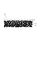
- FIG. 2 schematically shows a cross section of the electrode 20 obtained by plating the powder compact including the active material 21.
- the metal 22 is filled in the pores of the surface layer portion on the surface of one side of the powder molded body, and the metal coating 23 is formed on the surface of the one side of the powder molded body to produce a positive electrode or a negative electrode.
- the metal coating 23 formed on the surface of the powder compact exhibits a function as a current collector by having a certain thickness. At this time, it is necessary to perform plating only on one surface of the powder compact.
- the plating anode is placed only on the side where plating is desired, and the method is carried out without stirring the plating solution, or the side where the powder compact is not desired to be plated if necessary. Is effective.
- a coating of a metal other than aluminum can be produced by a normal aqueous plating method, but aluminum is difficult to produce by an aqueous plating method, and is melted as described in International Publication No. 2011/118460.
- An aluminum film can be formed by adopting a method of plating using a salt bath. Hereinafter, molten salt plating will be described.
- molten salt plating A direct current is applied in molten salt using the powder compact as a cathode and aluminum having a purity of 99.0% as an anode.
- the molten salt an organic molten salt that is a eutectic salt of an organic halide and an aluminum halide, or an inorganic molten salt that is a eutectic salt of an alkali metal halide and an aluminum halide can be used.
- the use of an organic molten salt bath that melts at a relatively low temperature is preferable because the binder resin contained in the powder molded body is not decomposed.
- the organic halide imidazolium salt, pyridinium salt and the like can be used, and specifically, 1-ethyl-3-methylimidazolium chloride (EMIC) and butylpyridinium chloride (BPC) are preferable.
- EMIC 1-ethyl-3-methylimidazolium chloride
- BPC butylpyridinium chloride
- molten salt bath a molten salt bath containing nitrogen is preferable, and among them, an imidazolium salt bath is preferably used.
- the imidazolium salt bath is preferable because it can be plated at a relatively low temperature.
- a salt containing an imidazolium cation having an alkyl group at the 1,3-position is preferably used.
- an aluminum chloride + 1-ethyl-3-methylimidazolium chloride (AlCl 3 + EMIC) molten salt is stable. Is most preferably used because it is high and difficult to decompose.
- the temperature of the molten salt bath is 10 ° C to 60 ° C, preferably 25 ° C to 45 ° C. The lower the temperature, the narrower the current density range that can be plated, and the more difficult it is to plate. If it exceeds 60 ° C., the binder resin in the powder molded body may be decomposed, so that it is preferably 60 ° C. or less.
- Separator A known or commercially available separator can be used.
- an insulating film made of polyolefin, polyethylene terephthalate, polyamide, polyimide, cellulose, glass fiber or the like is preferable.
- the average pore diameter of the separator is not particularly limited, and is usually about 0.01 to 5 ⁇ m, and the average thickness is usually about 10 to 150 ⁇ m.
- Non-aqueous electrolytes include, for example, a propylene carbonate solution in which tetraalkylphosphonium tetrafluoroborate is dissolved, a propylene carbonate solution or sulfolane solution in which tetraalkylammonium tetrafluoroborate is dissolved, and a propylene carbonate solution in which triethylmethylammonium tetrafluoroborate is dissolved.
- aqueous electrolyte examples include alkaline aqueous solutions such as an aqueous potassium hydroxide solution and an aqueous sodium hydroxide solution.
- alkaline aqueous solutions such as an aqueous potassium hydroxide solution and an aqueous sodium hydroxide solution.
- a nonaqueous electrolytic solution is preferable in the present invention. By using such an electrolytic solution, the capacitance can be improved.
- An electric double layer capacitor of the present invention is obtained by sandwiching a separator between a positive electrode and a negative electrode obtained by plating, and impregnating the positive electrode, the negative electrode and the separator with an electrolytic solution.
- Lithium ion capacitor Structure of lithium ion capacitor
- a separator is disposed between a pair of electrode materials composed of a positive electrode and a negative electrode, and the electrode material and the separator are impregnated with an electrolytic solution.
- the active material of the positive electrode for the lithium ion capacitor the same active carbon as the active material of the electrode for the electric double layer capacitor can be used.
- a negative electrode active material eg, graphite, lithium titanate (Li 4 Ti 5 O 12 )
- a negative electrode active material eg, graphite, lithium titanate (Li 4 Ti 5 O 12 )
- the potential of the negative electrode can be lowered and the cell voltage can be increased.Because the energy of the capacitor is proportional to the square of the voltage, It can be a capacitor with high energy.
- a method of occluding lithium in lithium in the negative electrode active material a method of immersing lithium ions in an electrolytic solution in a state where the negative electrode and a required amount of lithium metal are in contact with each other and applying heat, and a negative electrode and lithium metal
- a method in which lithium ions are occluded by facing each other through a separator and charging with constant current in an electrolytic solution is a method in which lithium ions are occluded by facing each other through a separator and charging with constant current in an electrolytic solution.
- the amount of occlusion of lithium ions in the negative electrode requires that the sum of the amount occluded in advance and the amount charged be equal to or less than the storable amount of the negative electrode.
- the positive electrode and the negative electrode may contain a conductive additive as necessary.
- the conductive auxiliary agent the same ones as described for the electric double layer capacitor can be used.
- Binder As the binder, the same binder as described for the electric double layer capacitor can be used.
- the positive electrode powder molded body and the negative electrode powder molded body of the lithium ion capacitor can be molded in the same manner as described for the production of the electrode material of the electric double layer capacitor.
- a positive electrode and a negative electrode of a lithium ion capacitor are prepared by performing plating treatment on each of the powder molded body for positive electrode and the powder molded body for negative electrode obtained above in the same manner as described for the production of the electrode material of the electric double layer capacitor. can do.
- Separator As the separator, the same separator as described for the electric double layer capacitor can be used.
- Electrode As an electrolyte solution for the negative electrode, a solution obtained by dissolving a lithium salt necessary for charging and discharging in an organic solvent can be used.
- the lithium salt for example, LiClO 4 , LiBF 4 , LiPF 6 or the like can be used. These may be used alone or in combination of any one or more.
- the solvent for dissolving the lithium salt for example, one or more selected from ethylene carbonate, propylene carbonate, butylene carbonate, dimethyl carbonate, diethyl carbonate, and ethyl methyl carbonate can be preferably used.
- LiPF 6 as the lithium salt and a mixed solution of ethylene carbonate and diethyl carbonate as the solvent. The ionic conductivity of the electrolyte is increased, and the internal resistance of the capacitor can be kept low.
- a lithium ion capacitor of the present invention is obtained by sandwiching a separator between a positive electrode and a negative electrode obtained by plating, and impregnating the positive electrode, the negative electrode, and the separator with an electrolytic solution.
- Example 1 Manufacture of EDLC positive electrode 1 -Manufacture of powder compact for positive electrode- Activated carbon powder (specific surface area: about 2200 m 2 / g, average particle size: about 6 ⁇ m) 80% by mass, Ketjen black 10% by weight as a conductive additive, 10% by mass of PTFE, knead and roll-roll.
- a sheet having a width of 10 cm, a length of 10 cm, and a thickness of 1.2 mm was obtained, and then the sheet was dried at 200 ° C. for 2 hours to obtain [EDLC positive electrode powder compact 1].
- [EDLC positive electrode 1] was obtained by applying a direct current having a current density of 3.6 A / dm 2 for 90 minutes to perform plating.
- the plating bath was stirred with a stirrer using a Teflon (registered trademark) rotor.
- Teflon registered trademark
- Example 3 Manufacture of LIC positive electrode 1
- [LIC positive electrode 1] was produced by the same production method as [EDLC positive electrode 1].
- the aluminum metal is coated on the surface of the active material and the solid electrolyte on the aluminum plate side of the counter electrode, and an aluminum film having a film thickness of 5 ⁇ m is formed on the outermost surface of the powder compact. It had been.
- Example 4 Manufacture of LIC negative electrode 1 -Manufacture of powder compact for negative electrode- As an active material, graphite powder having an average particle diameter of 10 ⁇ m was prepared, and this graphite powder, PTFE and ketjen black (conducting aid) were mixed at a mass ratio of 80:10:10. Ethanol was added dropwise to this mixture and mixed to prepare a powder mixture for a negative electrode powder compact. This powder mixture was roll-rolled to obtain a sheet having a width of 10 cm, a length of 10 cm and a thickness of 1.2 mm, and then the sheet was dried at 200 ° C. for 2 hours to obtain [Licium anode powder compact 1].
- Example 5 (Production of electric double layer capacitor 1) [EDLC positive electrode 1] and [EDLC negative electrode 1] were dried at 180 ° C. under reduced pressure for 5 hours. Each was cut to 3 cm ⁇ 3 cm and connected with tab leads. The surfaces of the electrodes on which the plating film was not formed faced each other, and a cellulose fiber separator (thickness 40 ⁇ m, density 0.45 g / cm 3 , porosity 70%) was placed therebetween.
- this laminate was housed in an aluminum laminate bag, and a non-aqueous electrolyte (a propylene carbonate solution in which 1 mol / l of tetraethylphosphonium tetrafluoroborate was dissolved) was impregnated in the electrode and the separator. Furthermore, the inside of the cell was reduced in pressure and sealed to prepare a test [Electric Double Layer Capacitor 1]. The rated voltage was 2.5V. Ten electric double layer capacitors having the same specifications were produced in the same manner.
- a non-aqueous electrolyte a propylene carbonate solution in which 1 mol / l of tetraethylphosphonium tetrafluoroborate was dissolved
- Example 6 (Production of lithium ion capacitor 1) [LIC positive electrode 1] and [LIC negative electrode 1] were dried at 180 ° C. under reduced pressure for 5 hours. Each was cut to 3 cm ⁇ 3 cm and connected with tab leads. The surfaces of the electrodes on which the plating film was not formed faced each other, and a cellulose fiber separator (thickness 40 ⁇ m, density 0.45 g / cm 3 , porosity 70%) was placed therebetween. Next, [LIC negative electrode 1] and a 10 ⁇ m-thick lithium metal foil to which a tab lead was connected face each other, and a polyolefin resin separator (thickness 20 ⁇ m, porosity 50%) was placed therebetween.
- This laminate is housed in an aluminum laminate bag and a non-aqueous electrolyte solution (an electrolyte solution in which 1 mol / L LiPF 6 is dissolved and ethylene carbonate (EC) and diethyl carbonate (DEC) are mixed at a volume ratio of 1: 1).
- a non-aqueous electrolyte solution an electrolyte solution in which 1 mol / L LiPF 6 is dissolved and ethylene carbonate (EC) and diethyl carbonate (DEC) are mixed at a volume ratio of 1: 1).
- EC ethylene carbonate
- DEC diethyl carbonate
- the capacitors of Examples 5 and 6 had a small change in capacitance even after 10,000 cycles, as in Comparative Examples 1 and 2. Therefore, it was found that the electric double layer capacitor of the present invention has a high capacitance and an excellent lifetime. From the above, it has been found that when the current collector of the present invention is used as an electrode for a capacitor, a capacitor superior in capacity and durability compared to a conventional capacitor can be provided.
Landscapes
- Engineering & Computer Science (AREA)
- Chemical & Material Sciences (AREA)
- Power Engineering (AREA)
- Materials Engineering (AREA)
- Microelectronics & Electronic Packaging (AREA)
- Electrochemistry (AREA)
- Chemical Kinetics & Catalysis (AREA)
- General Chemical & Material Sciences (AREA)
- Manufacturing & Machinery (AREA)
- Composite Materials (AREA)
- Electric Double-Layer Capacitors Or The Like (AREA)
- Cell Electrode Carriers And Collectors (AREA)
- Secondary Cells (AREA)
- Battery Electrode And Active Subsutance (AREA)
Priority Applications (4)
| Application Number | Priority Date | Filing Date | Title |
|---|---|---|---|
| KR1020147026016A KR20140138739A (ko) | 2012-03-29 | 2013-03-19 | 전극 재료 및, 이 전극 재료를 이용한 커패시터, 2차 전지 |
| CN201380016963.4A CN104246941A (zh) | 2012-03-29 | 2013-03-19 | 电极材料及采用该电极材料的电容器和二次电池 |
| DE112013001750.4T DE112013001750T5 (de) | 2012-03-29 | 2013-03-19 | Elektrodenmaterial sowie Kondensator und Sekundärbatterie, die das Elektrodenmaterial verwenden |
| US14/387,266 US20150093640A1 (en) | 2012-03-29 | 2013-03-19 | Electrode material, and capacitor and secondary battery using said electrode material |
Applications Claiming Priority (2)
| Application Number | Priority Date | Filing Date | Title |
|---|---|---|---|
| JP2012-076186 | 2012-03-29 | ||
| JP2012076186 | 2012-03-29 |
Publications (1)
| Publication Number | Publication Date |
|---|---|
| WO2013146464A1 true WO2013146464A1 (fr) | 2013-10-03 |
Family
ID=49259721
Family Applications (1)
| Application Number | Title | Priority Date | Filing Date |
|---|---|---|---|
| PCT/JP2013/057803 Ceased WO2013146464A1 (fr) | 2012-03-29 | 2013-03-19 | Matériau d'électrode, ainsi que condensateur et batterie rechargeable qui utilisent ledit matériau d'électrode |
Country Status (6)
| Country | Link |
|---|---|
| US (1) | US20150093640A1 (fr) |
| JP (1) | JPWO2013146464A1 (fr) |
| KR (1) | KR20140138739A (fr) |
| CN (1) | CN104246941A (fr) |
| DE (1) | DE112013001750T5 (fr) |
| WO (1) | WO2013146464A1 (fr) |
Cited By (2)
| Publication number | Priority date | Publication date | Assignee | Title |
|---|---|---|---|---|
| US10509470B2 (en) | 2014-06-06 | 2019-12-17 | Murata Manufacturing Co., Ltd. | Vibrating device |
| JP2022526441A (ja) * | 2019-03-29 | 2022-05-24 | コントロラマティクス コーポレーション | 電気活性化により高度に活性化された電極の製造方法 |
Families Citing this family (2)
| Publication number | Priority date | Publication date | Assignee | Title |
|---|---|---|---|---|
| CN106967998B (zh) * | 2017-05-19 | 2018-10-02 | 东北大学 | 以氧化锂为原料近室温电沉积制备Al-Li母合金的方法 |
| KR102263467B1 (ko) * | 2017-07-19 | 2021-06-11 | 주식회사 엘지에너지솔루션 | 집전체가 없는 전극 및 이를 포함하는 이차전지 |
Citations (5)
| Publication number | Priority date | Publication date | Assignee | Title |
|---|---|---|---|---|
| JPS594114A (ja) * | 1982-06-30 | 1984-01-10 | 松下電器産業株式会社 | 電気二重層キヤパシタ |
| JPS63175410A (ja) * | 1987-01-16 | 1988-07-19 | 日立コンデンサ株式会社 | 電気二重層コンデンサの製造方法 |
| JPH04293218A (ja) * | 1991-03-22 | 1992-10-16 | Asahi Glass Co Ltd | 電気二重層コンデンサ |
| JP2008034557A (ja) * | 2006-07-27 | 2008-02-14 | Kyoto Univ | 電極材料およびその製造方法 |
| JP2013084422A (ja) * | 2011-10-07 | 2013-05-09 | Nissan Motor Co Ltd | 電気デバイス用電極およびこの電極を用いた電気デバイス |
Family Cites Families (13)
| Publication number | Priority date | Publication date | Assignee | Title |
|---|---|---|---|---|
| WO1984000246A1 (fr) * | 1982-06-30 | 1984-01-19 | Matsushita Electric Industrial Co Ltd | Condensateur a double couche electrique |
| JPH024574Y2 (fr) * | 1986-10-15 | 1990-02-02 | ||
| DE69837838T2 (de) * | 1997-01-27 | 2008-01-31 | Fuji Jukogyo K.K. | Organische, elektrolytische batterie |
| JP2006286919A (ja) * | 2005-03-31 | 2006-10-19 | Fuji Heavy Ind Ltd | リチウムイオンキャパシタ |
| JP4857073B2 (ja) * | 2006-10-20 | 2012-01-18 | 富士重工業株式会社 | リチウムイオンキャパシタ |
| JP2009231234A (ja) * | 2008-03-25 | 2009-10-08 | Fuji Heavy Ind Ltd | 負極用炭素材料、蓄電デバイス、及び蓄電デバイス搭載品 |
| JP5038954B2 (ja) * | 2008-03-26 | 2012-10-03 | 富士重工業株式会社 | 電極の製造方法 |
| CN101546649A (zh) * | 2008-03-28 | 2009-09-30 | 富士重工业株式会社 | 电极的制造方法、蓄电装置及中间层叠材料 |
| KR101450978B1 (ko) * | 2009-12-18 | 2014-10-15 | 제이엑스 닛코 닛세키 킨조쿠 가부시키가이샤 | 리튬 이온 전지용 정극 및 그 제조 방법, 그리고 리튬 이온 전지 |
| JP5573146B2 (ja) * | 2009-12-21 | 2014-08-20 | パナソニック株式会社 | 電気化学素子 |
| CN103109397B (zh) * | 2010-09-29 | 2016-02-24 | 爱斯佩克株式会社 | 电极对干燥法、锂离子二次电池制造法、双电层电容器制造法、锂离子电容器制造法 |
| JP2012138319A (ja) * | 2010-12-28 | 2012-07-19 | Hitachi Ltd | リチウムイオン二次電池 |
| KR101559444B1 (ko) * | 2011-03-04 | 2015-10-12 | 가부시키가이샤 덴소 | 전지용 비수성 전해액 및 상기 전해액을 이용한 비수성 전해액 이차전지 |
-
2013
- 2013-03-19 US US14/387,266 patent/US20150093640A1/en not_active Abandoned
- 2013-03-19 KR KR1020147026016A patent/KR20140138739A/ko not_active Withdrawn
- 2013-03-19 DE DE112013001750.4T patent/DE112013001750T5/de not_active Withdrawn
- 2013-03-19 JP JP2014507750A patent/JPWO2013146464A1/ja active Pending
- 2013-03-19 WO PCT/JP2013/057803 patent/WO2013146464A1/fr not_active Ceased
- 2013-03-19 CN CN201380016963.4A patent/CN104246941A/zh active Pending
Patent Citations (5)
| Publication number | Priority date | Publication date | Assignee | Title |
|---|---|---|---|---|
| JPS594114A (ja) * | 1982-06-30 | 1984-01-10 | 松下電器産業株式会社 | 電気二重層キヤパシタ |
| JPS63175410A (ja) * | 1987-01-16 | 1988-07-19 | 日立コンデンサ株式会社 | 電気二重層コンデンサの製造方法 |
| JPH04293218A (ja) * | 1991-03-22 | 1992-10-16 | Asahi Glass Co Ltd | 電気二重層コンデンサ |
| JP2008034557A (ja) * | 2006-07-27 | 2008-02-14 | Kyoto Univ | 電極材料およびその製造方法 |
| JP2013084422A (ja) * | 2011-10-07 | 2013-05-09 | Nissan Motor Co Ltd | 電気デバイス用電極およびこの電極を用いた電気デバイス |
Cited By (4)
| Publication number | Priority date | Publication date | Assignee | Title |
|---|---|---|---|---|
| US10509470B2 (en) | 2014-06-06 | 2019-12-17 | Murata Manufacturing Co., Ltd. | Vibrating device |
| JP2022526441A (ja) * | 2019-03-29 | 2022-05-24 | コントロラマティクス コーポレーション | 電気活性化により高度に活性化された電極の製造方法 |
| JP7441855B2 (ja) | 2019-03-29 | 2024-03-01 | コントロラマティクス コーポレーション | 電気活性化により高度に活性化された電極の製造方法 |
| US12300801B2 (en) | 2019-03-29 | 2025-05-13 | Controlamatics Corporation | Process for producing highly activated electrode through electro-activation |
Also Published As
| Publication number | Publication date |
|---|---|
| KR20140138739A (ko) | 2014-12-04 |
| DE112013001750T5 (de) | 2015-04-02 |
| US20150093640A1 (en) | 2015-04-02 |
| JPWO2013146464A1 (ja) | 2015-12-10 |
| CN104246941A (zh) | 2014-12-24 |
Similar Documents
| Publication | Publication Date | Title |
|---|---|---|
| JP4929182B2 (ja) | 蓄電素子 | |
| US20150155107A1 (en) | Lithium ion capacitor | |
| CN105340120A (zh) | 锂电池 | |
| US20150303000A1 (en) | Lithium ion capacitor, power storage device, power storage system | |
| KR20160102974A (ko) | 알칼리 금속 이온 커패시터 | |
| US9553300B2 (en) | Electrode material; and battery, nonaqueous-electrolyte battery, and capacitor all incorporating the material | |
| CN105900198A (zh) | 锂离子电容器用正极和使用其的锂离子电容器 | |
| CN105745727A (zh) | 电容器及其制造方法 | |
| JP2012004491A (ja) | 蓄電デバイス | |
| WO2013146464A1 (fr) | Matériau d'électrode, ainsi que condensateur et batterie rechargeable qui utilisent ledit matériau d'électrode | |
| CN105706202A (zh) | 碱金属离子电容器及其制造方法和充放电方法 | |
| WO2013061789A1 (fr) | Condensateur | |
| JP2013143422A (ja) | リチウムイオンキャパシタ | |
| JP2012243924A (ja) | キャパシタ | |
| JP2005044821A (ja) | 電気二重層キャパシタ | |
| JP2012079813A (ja) | 蓄電デバイスの製造方法 | |
| JP6966276B2 (ja) | 電気化学デバイス用電解液および電気化学デバイス | |
| JP2014187383A (ja) | 金属多孔体を用いたキャパシタ | |
| JP2015095634A (ja) | 蓄電デバイスおよびその製造方法 | |
| JP5565112B2 (ja) | 金属多孔体を用いたキャパシタ | |
| WO2010092829A1 (fr) | Solution électrolytique et condensateur électrochimique l'utilisant | |
| KR102837698B1 (ko) | 전해질용 첨가제, 이를 포함하는 전해질 및 에너지 저장 디바이스 | |
| JP6718905B2 (ja) | リチウムイオンキャパシタ | |
| JP2009260187A (ja) | 蓄電デバイス | |
| JP2013115179A (ja) | リチウムイオンキャパシタ |
Legal Events
| Date | Code | Title | Description |
|---|---|---|---|
| 121 | Ep: the epo has been informed by wipo that ep was designated in this application |
Ref document number: 13769856 Country of ref document: EP Kind code of ref document: A1 |
|
| ENP | Entry into the national phase |
Ref document number: 2014507750 Country of ref document: JP Kind code of ref document: A |
|
| ENP | Entry into the national phase |
Ref document number: 20147026016 Country of ref document: KR Kind code of ref document: A |
|
| WWE | Wipo information: entry into national phase |
Ref document number: 14387266 Country of ref document: US |
|
| WWE | Wipo information: entry into national phase |
Ref document number: 1120130017504 Country of ref document: DE Ref document number: 112013001750 Country of ref document: DE |
|
| 122 | Ep: pct application non-entry in european phase |
Ref document number: 13769856 Country of ref document: EP Kind code of ref document: A1 |