WO2013146554A1 - 包装体、および包装体パッケージ - Google Patents
包装体、および包装体パッケージ Download PDFInfo
- Publication number
- WO2013146554A1 WO2013146554A1 PCT/JP2013/058172 JP2013058172W WO2013146554A1 WO 2013146554 A1 WO2013146554 A1 WO 2013146554A1 JP 2013058172 W JP2013058172 W JP 2013058172W WO 2013146554 A1 WO2013146554 A1 WO 2013146554A1
- Authority
- WO
- WIPO (PCT)
- Prior art keywords
- opening
- region
- package
- main body
- peeling
- Prior art date
- Legal status (The legal status is an assumption and is not a legal conclusion. Google has not performed a legal analysis and makes no representation as to the accuracy of the status listed.)
- Ceased
Links
Images


Classifications
-
- B—PERFORMING OPERATIONS; TRANSPORTING
- B65—CONVEYING; PACKING; STORING; HANDLING THIN OR FILAMENTARY MATERIAL
- B65D—CONTAINERS FOR STORAGE OR TRANSPORT OF ARTICLES OR MATERIALS, e.g. BAGS, BARRELS, BOTTLES, BOXES, CANS, CARTONS, CRATES, DRUMS, JARS, TANKS, HOPPERS, FORWARDING CONTAINERS; ACCESSORIES, CLOSURES, OR FITTINGS THEREFOR; PACKAGING ELEMENTS; PACKAGES
- B65D77/00—Packages formed by enclosing articles or materials in preformed containers, e.g. boxes, cartons, sacks or bags
- B65D77/10—Container closures formed after filling
- B65D77/20—Container closures formed after filling by applying separate lids or covers, i.e. flexible membrane or foil-like covers
- B65D77/2024—Container closures formed after filling by applying separate lids or covers, i.e. flexible membrane or foil-like covers the cover being welded or adhered to the container
- B65D77/2068—Means for reclosing the cover after its first opening
- B65D77/2096—Adhesive means
-
- B—PERFORMING OPERATIONS; TRANSPORTING
- B65—CONVEYING; PACKING; STORING; HANDLING THIN OR FILAMENTARY MATERIAL
- B65D—CONTAINERS FOR STORAGE OR TRANSPORT OF ARTICLES OR MATERIALS, e.g. BAGS, BARRELS, BOTTLES, BOXES, CANS, CARTONS, CRATES, DRUMS, JARS, TANKS, HOPPERS, FORWARDING CONTAINERS; ACCESSORIES, CLOSURES, OR FITTINGS THEREFOR; PACKAGING ELEMENTS; PACKAGES
- B65D75/00—Packages comprising articles or materials partially or wholly enclosed in strips, sheets, blanks, tubes or webs of flexible sheet material, e.g. in folded wrappers
- B65D75/52—Details
- B65D75/54—Cards, coupons or other inserts or accessories
- B65D75/56—Handles or other suspension means
- B65D75/566—Hand holes or suspension apertures
-
- B—PERFORMING OPERATIONS; TRANSPORTING
- B65—CONVEYING; PACKING; STORING; HANDLING THIN OR FILAMENTARY MATERIAL
- B65D—CONTAINERS FOR STORAGE OR TRANSPORT OF ARTICLES OR MATERIALS, e.g. BAGS, BARRELS, BOTTLES, BOXES, CANS, CARTONS, CRATES, DRUMS, JARS, TANKS, HOPPERS, FORWARDING CONTAINERS; ACCESSORIES, CLOSURES, OR FITTINGS THEREFOR; PACKAGING ELEMENTS; PACKAGES
- B65D75/00—Packages comprising articles or materials partially or wholly enclosed in strips, sheets, blanks, tubes or webs of flexible sheet material, e.g. in folded wrappers
- B65D75/52—Details
- B65D75/58—Opening or contents-removing devices added or incorporated during package manufacture
- B65D75/5894—Preformed openings provided in a wall portion and covered by a separate removable flexible element
-
- B—PERFORMING OPERATIONS; TRANSPORTING
- B65—CONVEYING; PACKING; STORING; HANDLING THIN OR FILAMENTARY MATERIAL
- B65D—CONTAINERS FOR STORAGE OR TRANSPORT OF ARTICLES OR MATERIALS, e.g. BAGS, BARRELS, BOTTLES, BOXES, CANS, CARTONS, CRATES, DRUMS, JARS, TANKS, HOPPERS, FORWARDING CONTAINERS; ACCESSORIES, CLOSURES, OR FITTINGS THEREFOR; PACKAGING ELEMENTS; PACKAGES
- B65D83/00—Containers or packages with special means for dispensing contents
- B65D83/08—Containers or packages with special means for dispensing contents for dispensing thin flat articles in succession
- B65D83/0805—Containers or packages with special means for dispensing contents for dispensing thin flat articles in succession through an aperture in a wall
- B65D83/0811—Containers or packages with special means for dispensing contents for dispensing thin flat articles in succession through an aperture in a wall with means for assisting dispensing
- B65D83/0835—Containers or packages with special means for dispensing contents for dispensing thin flat articles in succession through an aperture in a wall with means for assisting dispensing the articles being pulled out of the container
-
- B—PERFORMING OPERATIONS; TRANSPORTING
- B65—CONVEYING; PACKING; STORING; HANDLING THIN OR FILAMENTARY MATERIAL
- B65D—CONTAINERS FOR STORAGE OR TRANSPORT OF ARTICLES OR MATERIALS, e.g. BAGS, BARRELS, BOTTLES, BOXES, CANS, CARTONS, CRATES, DRUMS, JARS, TANKS, HOPPERS, FORWARDING CONTAINERS; ACCESSORIES, CLOSURES, OR FITTINGS THEREFOR; PACKAGING ELEMENTS; PACKAGES
- B65D2575/00—Packages comprising articles or materials partially or wholly enclosed in strips, sheets, blanks, tubes or webs of flexible sheet material, e.g. in folded wrappers
- B65D2575/52—Details
- B65D2575/54—Cards, coupons, or other inserts or accessories
- B65D2575/56—Handles or other suspension means
- B65D2575/565—Handles or other suspension means means explicitly used for suspending
-
- B—PERFORMING OPERATIONS; TRANSPORTING
- B65—CONVEYING; PACKING; STORING; HANDLING THIN OR FILAMENTARY MATERIAL
- B65D—CONTAINERS FOR STORAGE OR TRANSPORT OF ARTICLES OR MATERIALS, e.g. BAGS, BARRELS, BOTTLES, BOXES, CANS, CARTONS, CRATES, DRUMS, JARS, TANKS, HOPPERS, FORWARDING CONTAINERS; ACCESSORIES, CLOSURES, OR FITTINGS THEREFOR; PACKAGING ELEMENTS; PACKAGES
- B65D2575/00—Packages comprising articles or materials partially or wholly enclosed in strips, sheets, blanks, tubes or webs of flexible sheet material, e.g. in folded wrappers
- B65D2575/52—Details
- B65D2575/58—Opening or contents-removing devices added or incorporated during package manufacture
- B65D2575/586—Opening or contents-removing devices added or incorporated during package manufacture with means for reclosing
Definitions
- the present invention relates to a package that accommodates the contents so as to be removable and a package package that includes the package that contains the contents.
- JP 2010-13144 describes a package containing a wet tissue.
- the main body of this package is formed of a heat-sealing film.
- the lid of the package is bonded to the main body so as to cover the opening of the main body.
- the lid is bonded to the main body via an adhesive so as to be repeatedly peelable.
- an object of this invention is to provide the improvement technique regarding the adhesiveness with respect to the main body of a lid
- the main body is formed of a sheet member having an opening opened to the outside, and an accommodation space communicating with the opening is formed inside.
- a packaging body that covers the opening and has a lid that can open and close the opening is configured.
- the said package is comprised so that the container accommodated in the accommodation space can be taken out from an opening part.
- the main body is formed extending in the first direction.
- the main body has a holding portion for holding the main body formed in the region of one end in the first direction.
- the lid includes a fixing part fixed to the main body part and a peeling part connected to the fixing part and configured to be peelable from the main body part via an adhesive.
- the peeling portion is connected to one end side from the fixing portion in the first direction.
- the main body portion is surrounded by the first region where the fixing portion is fixed, the second region where the peeling portion is bonded via the first adhesive, and the first region and the second region.
- the third region is formed. Further, the opening is formed in the third region.
- the opening is formed in the third region surrounded by the first region where the lid is fixed without being peeled off and the second region where the lid is peeled off. That is, with respect to the first direction, the portion between the opening in the third region and the first region and the lid are not bonded with the first adhesive. Therefore, compared with the case where the said part is adhere
- the second region is arranged at a position where each straight line connecting each portion constituting the second region and the holding portion does not overlap the opening. It is configured.
- the tensile force generated by the force that peels off the lid acts linearly between the holding part and the part to be peeled off. For this reason, if an opening is provided between the holding portion and the part to be peeled off, the opening is deformed by the tensile force.
- no opening is formed on a straight line connecting each portion of the second region and the holding portion. Therefore, it can suppress that an opening part deform
- the holding portion is formed as a hanging portion for hanging the main body portion.
- the hanging part is preferably a through hole penetrating the main body part.
- the hook etc. which were attached to the main-body part may be sufficient.
- the hanging portion has a strength that prevents the hanging portion from being destroyed when the peeling portion is peeled from the main body portion in a state where the main body portion is hung. That is, the suspending portion has a section modulus that is not broken by the force generated by the peeling and the force acting by the weight of the package containing the contents when the peeling portion is peeled from the main body portion. “Fracture” is a concept that includes not only an aspect in which the holding part cannot perform the function of holding the main body part but also an aspect in which irreversible deformation (plastic deformation) occurs in the holding part.
- the packaging body can be used in a suspended state by the suspending section as the holding section of the packaging body. Therefore, it is not necessary to peel the lid from the main body while the user is holding the main body. That is, the user can peel the lid with one hand. Thereby, a user's operation is simplified.
- the peeling part has an outer shape formed by a connecting part connected to the fixing part and an outer edge part other than the connecting part.
- the adhesive is applied only to the outer edge portion.
- the lid has a gripping part that is connected to the peeling part on the side opposite to the bonding part of the peeling part in the first direction and is gripped by the user.
- the lid since the lid has the grip portion, the user can easily peel the lid from the main body sheet by gripping the grip portion. That is, the user's operation is simplified.
- the third region is formed with the opening portion and a separation portion non-permissible region in which adhesion with the separation portion is not allowed.
- the sealing property of the opening can be improved.
- the third region is bonded with the second adhesive having a smaller force required to peel the peeling portion than the first adhesive, the tensile force generated by the peeling of the lid is mainly peeled. A large force is required between the first region and the holding portion. Therefore, the second adhesive can suppress the deformation of the opening while improving the adhesion of the opening.
- the package package is composed of a sheet member having an opening portion opened to the outside, a main body portion in which a housing space communicating with the opening portion is formed, and covers the opening portion.
- a package package comprising a package having an openable / closable lid and a container accommodated in the accommodation space so as to be removable from the opening.
- the main body is formed extending in the first direction.
- the main body has a holding portion for holding the main body formed in the region of one end in the first direction.
- the lid includes an adhesive portion bonded to the main body portion and a peeling portion that is connected to the adhesive portion and configured to be peelable from the main body portion.
- the peeling portion is connected to one end side from the bonding portion in the first direction.
- the main body portion is surrounded by the first region where the fixing portion is fixed, the second region where the peeling portion is bonded via the first adhesive, and the first region and the second region.
- the third region is formed. Further, the opening is formed in the third region.
- the opening is formed in the third region surrounded by the first region where the lid is fixed without being peeled off and the second region where the lid is peeled off. That is, with respect to the first direction, the portion between the opening in the third region and the first region and the lid are not bonded with the first adhesive. Therefore, compared with the case where the said part is adhere
- region is arrange
- the tensile force generated by the force that peels off the lid acts linearly between the holding part and the part to be peeled off. For this reason, if an opening is provided between the holding portion and the part to be peeled off, the opening is deformed by the tensile force.
- no opening is formed on a straight line connecting each portion of the second region and the holding portion. Therefore, it can suppress that an opening part deform
- the holding part is formed as a hanging part for hanging the main body part. Furthermore, the third region has an opening and is detachably bonded to the peeling portion via a second adhesive that requires less force to peel the peeling portion than the first adhesive. Yes.
- the present embodiment it is possible to suppress the deformation of the opening when the lid body is peeled off from the main body in the state where the weight of the contents generated when the main body is suspended. it can.
- FIG. 5 is a sectional view taken along line VV in FIG. 2. It is a front view which shows the state which suspended the package. It is a top view equivalent to FIG. 4 of the package which concerns on the 1st modification of this invention. It is sectional drawing equivalent to FIG. 5 of the package which concerns on the 1st modification of this invention. It is a top view equivalent to FIG. 4 of the package which concerns on the 2nd modification of this invention. It is sectional drawing equivalent to FIG. 5 of the package which concerns on the 2nd modification of this invention.
- the wet tissue 130 means a material (for example, non-woven fabric, gauze, cotton sheet, tissue paper) in which a fibrous material is formed in a sheet shape, impregnated with a liquid (eg, alcohol, disinfectant, lotion) or the like.
- a liquid eg, alcohol, disinfectant, lotion
- the wet tissue 130 corresponds to the “containment” of the present invention.
- the package 100 in which the wet tissue 130 is accommodated is an implementation configuration example corresponding to the “package package” in the present invention.
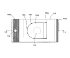
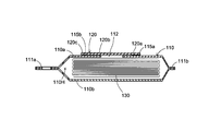
- the package 100 is composed of a main body 110 and a lid 120.
- the main body 110 corresponds to the “main body portion” of the present invention
- the lid 120 corresponds to the “lid body” of the present invention.
- the main body 110 of the package 100 is formed of an upper wall 110a and a bottom wall 110b, and has a wet tissue storage space 110H for storing the wet tissue 130. Further, the main body 110 of the package 100 has an opening 112 formed in the upper wall 110a.
- the wet tissue accommodation space 110H is an implementation configuration example corresponding to the “accommodation space” of the present invention.
- the wet tissue 130 is accommodated in the wet tissue accommodating space 110H so that it can be sequentially taken out from the opening 112.
- a part of the wet tissue 130 to be taken out next is accommodated so as to protrude from the opening 112.
- the folded wet tissues 130 are stacked so that the folding directions are alternately reversed.
- the lamination is performed so that the end of the lower side of the wet tissue 130 (the lower side of the laminated body) is arranged below the end of the upper side of the wet tissue 130 to be taken out (the upper side of the laminated body). To do.
- the main body 110 of the package 100 is formed of, for example, a film that can be fused by heating (referred to as a “thermal fusion film”).
- the main body 110 of the package 100 wraps the wet tissue 130 with a heat-sealing film and presses the vertical seal portion (not shown) and the horizontal seal portions 111a and 111b on which the heat-sealing film is stacked. It is formed by heating and bonding the heat-sealing film at the vertical seal part and the horizontal seal part 111a, 111b.
- the vertical seal portion is formed in the lower part of the main body 110 along the conveyance direction of the heat-sealing film when the package 100 is manufactured.
- the lateral seal portions 111a and 111b are formed along the direction orthogonal to the transport direction of the heat-sealing film at the front and back locations separated along the transport direction of the heat-sealing film when the package 100 is manufactured.
- the horizontal seal portion 111 a is formed longer than the horizontal seal portion 111 b in the long side direction of the main body 110 (the left-right direction in FIG. 2).
- a circular suspension hole 114 penetrating the horizontal seal portion 111a is formed at a substantially central portion of the horizontal seal portion 111a.
- the long side direction of the main body 110 is an implementation configuration example corresponding to the “first direction” in the present invention.
- the heat-sealing film forming the main body 110 of the package 100 various films that can be fused by heating can be used.
- a film that can maintain the wet state of the wet tissue 130 (can prevent drying) is laminated.
- a protective layer made of polyethylene terephthalate (PET) resin, a wet retention layer made of aluminum (anti-drying layer), and a heat sealing layer made of biaxially stretched polypropylene resin (heat seal layer) are laminated.
- a laminated film (laminated film) is used.
- the heat-sealing is performed so that the heat-sealing layers (biaxially stretched polypropylene resin layers) face each other in the vertical seal portion and the horizontal seal portion. Stack the films. Thereby, when a vertical seal part and a horizontal seal part are heated, the opposing heat-sealing layer (biaxially stretched polypropylene resin layer) is melted and joined. Note that the protective layer can be omitted.
- the wet retention layer is not limited to the aluminum layer as long as it can maintain the wet state of the wet tissue 130 accommodated in the wet tissue accommodation space 110H (prevent drying).
- fusion layer should just be melt
- This heat-sealing film is an implementation configuration example corresponding to the “sheet member” in the present invention.
- the opening 112 can be formed in various shapes that allow the wet tissue 130 to be removed from the wet tissue storage space 110H. For example, it can be formed in an elliptical shape, a circular shape, or a rectangular shape having a major axis and a minor axis. In the present embodiment, an opening 112 having a circular shape is formed. This opening 112 is an implementation configuration example corresponding to the “opening” in the present invention.
- the lid 120 is formed on the opening / closing part 120b, the base part 120a extending from the opening / closing part 120b to the side seal part 111b, and the side seal part 111a side (the side opposite to the base part 120a) from the opening / closing part 120b. It has the knob part 120c.
- the opening / closing part 120 b has an area larger than the area of the opening 112.
- cover 120 is adhere
- the base 120a is fixed to the main body 110 with an adhesive 115a.
- the opening / closing part 120b is detachably bonded to the main body 110 by an adhesive 115b.
- a pressure-sensitive adhesive is used as the adhesive 115b.
- the knob 120c is used as a knob for operating the opening / closing part 120b.
- the base part 120a, the opening / closing part 120b, and the knob part 120c are implementation examples corresponding to the “fixing part”, the “peeling part”, and the “gripping part” in the present invention, respectively.
- the adhesive 115b is an implementation configuration example corresponding to the “first adhesive” in the present invention.
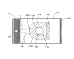
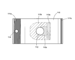
- the adhesive 115a is applied to the entire surface of the base 120a. Thereby, the base 120a is fixed to the fixing region 113a of the main body 110 shown in FIG.
- the adhesive 115b is applied to a partial region of the opening / closing part 120b. That is, the adhesive 115b is applied only to a region corresponding to the peeling region 113b of the main body 110 shown in FIG.
- the peeling area 113b is composed of a first peeling area 113b1 and a second peeling area 113b2.
- the first peeling region 113b1 is a region surrounded by the tangent lines L1 and L2 of the opening 112 passing through the hanging hole 114 and an outline corresponding to the outer edge of the opening / closing part 120b.
- the second peeling region 113b2 is a region on the side of the suspension hole 114 of the opening 112, and is a region surrounded by the tangent lines L1 and L2, the opening 112, and an outline corresponding to the outer edge of the opening / closing part 120b.
- the opening formation region 113c is formed so as to be surrounded by the fixing region 113a and the peeling region 113b.
- the opening 112 is disposed in the opening formation region 113c.
- the fixing region 113a, the separation region 113b, and the opening formation region 113c are implementation examples corresponding to the “first region”, “second region”, and “third region” in the present invention, respectively.
- an opening 112 is formed, and a peeling portion adhesion non-permissible region in which adhesion to the opening / closing portion 120b is not allowed is set.
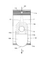
- the knob 120c of the lid 120 is picked and the opening / closing part 120b is peeled off from the surface of the main body 110. Thereby, the opening / closing part 120b is peeled from the main body 110, and the opening 112 is opened. In a normal state, the opening / closing part 120b is bonded to the surface of the main body 110 in order to prevent the wet tissue 130 from drying.
- the horizontal seal portion 111 a may be held by passing the rope 200 for suspension through the suspension hole 114 and holding the main body 110 by the rope 200. By suspending and holding the main body 110, the lid 120 peeled in the direction of arrow A is kept peeled by its own weight.
- This hanging hole 114 is an implementation configuration example corresponding to the “holding portion”, “hanging portion”, and “through hole” in the present invention.
- the suspension holes 114 are arranged so that the diameter of the suspension holes 114 and the sides around the suspension holes 114 are not broken so that the suspension holes 114 are not broken even if the lid 120 is peeled off while the body 110 is suspended and held.
- the strength of the seal part 111a is set. Specifically, when the lid 120 is peeled off, the suspension hole 114 is formed against the tensile force generated in the heat-sealing film due to the peeling of the adhesive and the tensile force generated in the heat-sealing film due to the weight of the package 100.
- the hole diameter of the hanging hole 114 and the section modulus of the lateral seal portion 111a are set so as not to be destroyed.
- the package 100 has a weight of 5 g
- the wet tissue 130 has a weight of 25 g
- the hole diameter of the hanging hole 114 is 5 mm
- the peel strength of the lid 120 when the peel speed is 100 mm / min is 250 g.
- the film tear strength of the lateral seal portion 111a is set so as to have a strength of 280 g or more in total.
- the user When the wet tissue 130 is not used, the user returns the knob 120c to the opening 112 side and adheres the opening / closing part 120b to the surface of the main body 110 in order to prevent the wet tissue 130 from drying.
- the packaging body 100 can be held in a suspended state. Therefore, the lid 120 can be peeled from the main body 110 while the packaging body 100 is suspended. Therefore, the user can peel the lid 120 with one hand. That is, the operability of peeling off the lid 120 is simplified.
- the lid 120 since the lid 120 is peeled off in a state where the package 100 is suspended, the lid 120 is kept peeled by its own weight. Therefore, the user can take out the wet tissue 130 from the opening with one hand after peeling the lid 120 from the main body 110 with one hand. That is, since the user can perform all operations with only one hand, the operability is simplified.
- the tensile force generated by the force for peeling the opening / closing portion 120b acts linearly between the hanging hole 114 and the peeling region 113b for peeling the adhesive 115b. Therefore, if the opening 112 is provided on a straight line that connects each part of the hanging hole 114 and the peeling region 113b, the opening 112 is deformed by the tensile force. However, according to the present embodiment, the opening 112 is not formed on a straight line that connects each part of the hanging hole 114 and the peeling region 113b, and therefore the opening 112 is directly pulled in the long side direction of the main body 110. There is nothing. That is, the opening 112 can be prevented from being deformed by the tensile force. Accordingly, when the opening 120 is covered again with the lid 120 after the lid 120 is peeled off, the adhesion between the lid 120 and the main body 110 is improved. Therefore, drying of the wet tissue 130 can be suppressed.
- the peeling area 213b is configured on the main body 110 corresponding to the outer edge of the opening / closing part 120b of the lid 120. Unlike the above-described embodiment, the peeling region 213b is disposed away from the opening 112 without contacting the opening 112. As shown in FIG. 8, the adhesive 115b is applied only to the outer edge of the opening / closing part 120b.
- the opening is caused by the tensile force generated when the opening / closing part 120b is separated from the main body 110.
- the deformation of 112 can be further suppressed.
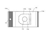
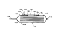
- the lid 120 is detachably bonded to the opening forming region 113c via the adhesive 115c.
- the configuration other than the adhesive 115c is the same as that of the present embodiment.
- the lid 120 is bonded to the main body 110 with adhesives 115a, 115b, and 115c.
- the adhesive 115c adheres the opening / closing part 120b and the opening forming region 113c of the main body 110 in a peelable manner.
- the adhesive 115c has a weaker adhesive force than the adhesive 115b. That is, the force required to peel the portion bonded with the adhesive 115c is smaller than the portion bonded with the adhesive 115b.
- the adhesive 115c is applied to the opening / closing part 120b corresponding to the hatched area other than the opening 112 of the opening forming area 113c shown in FIG.
- This adhesive 115c is an implementation structural example corresponding to the "second adhesive" in the present invention.
- the sealing property of the opening 112 can be improved.
- the opening forming region is bonded by the adhesive 115c having a smaller force required to peel the opening / closing part 120b than the adhesive 113b and the adhesive 115b. Therefore, the tensile force generated by the peeling of the opening / closing part 120b is mainly generated between the peeling region 113b bonded with the adhesive 115b having a large force necessary for peeling and the hanging hole 114. Therefore, the adhesive 115c can suppress the deformation of the opening 112 while improving the adhesion of the opening 112.
- the hanging hole 114 is provided in the horizontal seal portion 111a of the main body 110 as the hanging portion, but the present invention is not limited to this.
- a hook or the like may be attached to the main body 110 so that the main body 110 can be suspended.
- the horizontal seal part 111a of the main body 110 may be provided with an adhesive tape so that the main body 110 can be suspended.
- the package 100 was demonstrated so that it might be used in the suspended state, it is not restricted to this.
- the package 100 may be held by fixing the horizontal seal portion 111a to a predetermined fixing location such as a desk or shelf.
- the knob 120c is formed on the lid 120, but the knob 120c may not be formed. Further, as the shape of the knob portion 120c, for example, it may be configured to protrude further in the direction of the lateral seal portion 111a with respect to the lid 120 without being integrally formed with the same curvature as the curved portion of the lid 120. .
- the wet tissue 130 is folded in a so-called pop-up form and accommodated in the package 100, but is not limited thereto.
- the wet tissue 130 is folded into a so-called pocket fold which is a zigzag fold in which the edge of the Z fold is further folded and then folded in half at the center of the fold line. May be.
- the present invention is not limited to sheet-like articles such as wet tissues, and can be configured as a package that accommodates various articles.
- the package according to the present invention can be configured in the following modes.
- a main body part comprising a sheet member having an opening opened to the outside, and a housing space communicating with the opening formed inside, A cover that covers the opening and is capable of opening and closing the opening;
- the main body portion is formed to extend in the first direction, and has a holding portion for holding the main body portion formed in a region of one end portion in the first direction
- the lid body includes a fixing portion fixed to the main body portion, and a peeling portion configured to be connected to the fixing portion and peelable from the main body portion via a first adhesive, The peeling portion is connected to the one end side from the fixing portion in the first direction,
- the main body portion is entirely composed of a first region to which the fixing portion is fixed, a second region to which the peeling portion is bonded via the first adhesive, and the first region and the second region.
- a third region surrounded by the region is formed, The package is characterized in that the opening is formed in the third region.
- a package according to aspect 1 The second area is configured such that each straight line connecting each portion constituting the second area and the holding portion is arranged at a position not overlapping the opening. body.
- the package according to aspect 1 or 2 The package according to aspect 1 or 2, The said holding
- a package according to aspect 3 The packaging body, wherein the hanging portion is a through-hole penetrating the main body portion.
- a package according to any one of aspects 1 to 5 The peeling part has an outer shape of the peeling part formed by a connecting part connected to the fixing part and an outer edge part other than the connecting part, The packaging body, wherein the adhesive is applied only to the outer edge.
- a package according to any one of aspects 1 to 6 The said cover body has a holding part connected with the said peeling part on the opposite side to the said adhering part of the said peeling part in the said 1st direction, and is gripped by the user.
- a main body part comprising a sheet member having an opening opened to the outside, and a housing space communicating with the opening formed inside,
- a packaging body that covers the opening and has a lid that can open and close the opening;
- a package package comprising: an item contained in the accommodation space so as to be removable from the opening;
- the main body portion is formed to extend in the first direction, and has a holding portion for holding the main body portion formed in a region of one end portion in the first direction
- the lid body includes a fixing portion fixed to the main body portion, and a peeling portion configured to be connected to the fixing portion and peelable from the main body portion via a first adhesive, The peeling portion is connected to the one end side from the fixing portion in the first direction,
- the main body portion is entirely composed of a first region to which the fixing portion is fixed, a second region to which the peeling portion is bonded via the first adhesive, and the first region and the second region.
- a third region surrounded by the region is formed, The package is characterized in that the opening is formed in the third region.
- the package package according to aspect 10 The second area is configured such that each straight line connecting each portion constituting the second area and the holding portion is arranged at a position not overlapping the opening.
- Body package. The package package according to aspect 10 or 11, The packaging body package, wherein the holding portion is formed as a hanging portion for hanging the main body portion.
- Packaging body 110 Main body 110a Upper wall 110b Bottom wall 110H Storage space 111a Lateral seal part 111b Lateral seal part 112 Opening 112a Through hole 112b Through hole 113a Fixing area (1st area) 113b Peeling area (second area) 113b1 First peeling region 113b2 Second peeling region 113c Opening formation region (third region) 114 Suspension hole 115a Adhesive 115b Adhesive (first adhesive) 115c Adhesive (second adhesive) 120 Lid 120a Base 120b Opening / closing part 120c Knob part 130 Wet tissue 200 Rope 213b Peeling area L1 Tangent L2 Tangent
Landscapes
- Engineering & Computer Science (AREA)
- Mechanical Engineering (AREA)
- Containers And Packaging Bodies Having A Special Means To Remove Contents (AREA)
- Packages (AREA)
Description
次に、図7、図8を参照しつつ、上記本実施形態を変更した第1変形例について説明する。第1変更例においては、図7に示すように、剥離領域213bが構成されている。剥離領域213b以外の構成は、上記本実施形態と同様である。
次に、図9、図10を参照しつつ、上記本実施形態を変更した第2変形例について説明する。第2変更例においては、蓋120が接着剤115cを介して開口形成領域113cに剥離可能に接着されている。接着剤115c以外の構成は、上記本実施形態と同様である。
(態様1)
外部に開放された開口部を有するシート部材からなり、前記開口部に連通した収容空間が内部に形成された本体部と、
前記開口部を覆い、前記開口部を開閉可能な蓋体と、を有し、
前記収容空間に収容された収容物を前記開口部から取り出し可能な包装体であって、
前記本体部は、第1方向に延在して形成されており、前記第1方向における一方の端部の領域に形成された当該本体部を保持するための保持部を有し、
前記蓋体は、前記本体部に固着された固着部と、前記固着部に連接し前記本体部に対して第1接着剤を介して剥離可能に構成された剥離部と、を有し、
前記剥離部は、前記第1方向における前記固着部から前記一方の端部側に連接されており、
前記本体部には、前記固着部が固着された第1領域と、前記第1接着剤を介して前記剥離部が接着された第2領域と、前記第1領域と前記第2領域とで全領域を囲まれた第3領域とが形成されており、
前記開口部は、前記第3領域内に形成されていることを特徴とする包装体。
(態様2)
態様1に記載の包装体であって、
前記第2領域は、当該第2領域を構成する各箇所と前記保持部とを結ぶそれぞれの直線が、前記開口部と重ならない位置に配置されるように構成されていることを特徴とする包装体。
(態様3)
態様1または2に記載の包装体であって、
前記保持部は、前記本体部を吊下げるための吊下げ部として形成されていることを特徴とする包装体。
(態様4)
態様3に記載の包装体であって、
前記吊下げ部は、前記本体部を貫通した貫通穴であることを特徴とする包装体。
(態様5)
態様3または4に記載の包装体であって、
前記吊下げ部は、前記本体部が吊下げられた状態で、前記剥離部を前記本体部から剥離させたときに、前記吊下げ部が破壊されない強度を有することを特徴とする包装体。
(態様6)
態様1~5のいずれか1項に記載の包装体であって、
前記剥離部は、前記固着部と連接する連接部と、当該連接部以外の外縁部とで、当該剥離部の外形が形成されており、
前記接着剤は、前記外縁部のみに塗着されていることを特徴とする包装体。
(態様7)
態様1~6のいずれか1項に記載の包装体であって、
前記蓋体は、前記第1方向における前記剥離部の前記固着部と反対側において前記剥離部と連接された、ユーザに把持される把持部を有することを特徴とする包装体。
(態様8)
態様1~7のいずれか1項に記載の包装体であって、
前記第3領域は、前記開口部が形成されているとともに、前記剥離部との接着が許容されない剥離部接着非許容領域が設定されていることを特徴とする包装体。
(態様9)
態様1~7のいずれか1項に記載の包装体であって、
前記第3領域は、前記開口部が形成されているとともに、前記第1接着剤よりも前記剥離部を剥離させるために必要な力が小さい第2接着剤を介して前記剥離部に剥離可能に接着されていることを特徴とする包装体。
(態様10)
外部に開放された開口部を有するシート部材からなり、前記開口部に連通した収容空間が内部に形成された本体部と、
前記開口部を覆い、前記開口部を開閉可能な蓋体と、を有する包装体と、
前記開口部から取り出し可能に前記収容空間に収容された収容物と、からなる包装体パッケージであって、
前記本体部は、第1方向に延在して形成されており、前記第1方向における一方の端部の領域に形成された当該本体部を保持するための保持部を有し、
前記蓋体は、前記本体部に固着された固着部と、前記固着部に連接し前記本体部に対して第1接着剤を介して剥離可能に構成された剥離部と、を有し、
前記剥離部は、前記第1方向における前記固着部から前記一方の端部側に連接されており、
前記本体部には、前記固着部が固着された第1領域と、前記第1接着剤を介して前記剥離部が接着された第2領域と、前記第1領域と前記第2領域とで全領域を囲まれた第3領域とが形成されており、
前記開口部は、前記第3領域内に形成されていることを特徴とする包装体パッケージ。
(態様11)
態様10に記載の包装体パッケージであって、
前記第2領域は、当該第2領域を構成する各箇所と前記保持部とを結ぶそれぞれの直線が、前記開口部と重ならない位置に配置されるように構成されていることを特徴とする包装体パッケージ。
(態様12)
態様10または11に記載の包装体パッケージであって、
前記保持部は、前記本体部を吊下げるための吊下げ部として形成されていることを特徴とする包装体パッケージ。
(態様13)
態様10~12のいずれか1項に記載の包装体パッケージであって、
前記第3領域は、前記開口部が形成されているとともに、前記第1接着剤よりも前記剥離部を剥離させるために必要な力が小さい第2接着剤を介して前記剥離部に剥離可能に接着されていることを特徴とする包装体パッケージ。
110 本体
110a 上壁
110b 底壁
110H 収容空間
111a 横シール部
111b 横シール部
112 開口
112a 貫通穴
112b 貫通穴
113a 固着領域(第1領域)
113b 剥離領域(第2領域)
113b1 第1剥離領域
113b2 第2剥離領域
113c 開口形成領域(第3領域)
114 吊下げ穴
115a 接着剤
115b 接着剤(第1接着剤)
115c 接着剤(第2接着剤)
120 蓋
120a 基部
120b 開閉部
120c 摘み部
130 ウェットティッシュ
200 ロープ
213b 剥離領域
L1 接線
L2 接線
Claims (13)
- 外部に開放された開口部を有するシート部材からなり、前記開口部に連通した収容空間が内部に形成された本体部と、
前記開口部を覆い、前記開口部を開閉可能な蓋体と、を有し、
前記収容空間に収容された収容物を前記開口部から取り出し可能な包装体であって、
前記本体部は、第1方向に延在して形成されており、前記第1方向における一方の端部の領域に形成された当該本体部を保持するための保持部を有し、
前記蓋体は、前記本体部に固着された固着部と、前記固着部に連接し前記本体部に対して第1接着剤を介して剥離可能に構成された剥離部と、を有し、
前記剥離部は、前記第1方向における前記固着部から前記一方の端部側に連接されており、
前記本体部には、前記固着部が固着された第1領域と、前記第1接着剤を介して前記剥離部が接着された第2領域と、前記第1領域と前記第2領域とで全領域を囲まれた第3領域とが形成されており、
前記開口部は、前記第3領域内に形成されていることを特徴とする包装体。 - 請求項1に記載の包装体であって、
前記第2領域は、当該第2領域を構成する各箇所と前記保持部とを結ぶそれぞれの直線が、前記開口部と重ならない位置に配置されるように構成されていることを特徴とする包装体。 - 請求項1または2に記載の包装体であって、
前記保持部は、前記本体部を吊下げるための吊下げ部として形成されていることを特徴とする包装体。 - 請求項3に記載の包装体であって、
前記吊下げ部は、前記本体部を貫通した貫通穴であることを特徴とする包装体。 - 請求項3または4に記載の包装体であって、
前記吊下げ部は、前記本体部が吊下げられた状態で、前記剥離部を前記本体部から剥離させたときに、前記吊下げ部が破壊されない強度を有することを特徴とする包装体。 - 請求項1~5のいずれか1項に記載の包装体であって、
前記剥離部は、前記固着部と連接する連接部と、当該連接部以外の外縁部とで、当該剥離部の外形が形成されており、
前記接着剤は、前記外縁部のみに塗着されていることを特徴とする包装体。 - 請求項1~6のいずれか1項に記載の包装体であって、
前記蓋体は、前記第1方向における前記剥離部の前記固着部と反対側において前記剥離部と連接された、ユーザに把持される把持部を有することを特徴とする包装体。 - 請求項1~7のいずれか1項に記載の包装体であって、
前記第3領域は、前記開口部が形成されているとともに、前記剥離部との接着が許容されない剥離部接着非許容領域が設定されていることを特徴とする包装体。 - 請求項1~7のいずれか1項に記載の包装体であって、
前記第3領域は、前記開口部が形成されているとともに、前記第1接着剤よりも前記剥離部を剥離させるために必要な力が小さい第2接着剤を介して前記剥離部に剥離可能に接着されていることを特徴とする包装体。 - 外部に開放された開口部を有するシート部材からなり、前記開口部に連通した収容空間が内部に形成された本体部と、
前記開口部を覆い、前記開口部を開閉可能な蓋体と、を有する包装体と、
前記開口部から取り出し可能に前記収容空間に収容された収容物と、からなる包装体パッケージであって、
前記本体部は、第1方向に延在して形成されており、前記第1方向における一方の端部の領域に形成された当該本体部を保持するための保持部を有し、
前記蓋体は、前記本体部に固着された固着部と、前記固着部に連接し前記本体部に対して第1接着剤を介して剥離可能に構成された剥離部と、を有し、
前記剥離部は、前記第1方向における前記固着部から前記一方の端部側に連接されており、
前記本体部には、前記固着部が固着された第1領域と、前記第1接着剤を介して前記剥離部が接着された第2領域と、前記第1領域と前記第2領域とで全領域を囲まれた第3領域とが形成されており、
前記開口部は、前記第3領域内に形成されていることを特徴とする包装体パッケージ。 - 請求項10に記載の包装体パッケージであって、
前記第2領域は、当該第2領域を構成する各箇所と前記保持部とを結ぶそれぞれの直線が、前記開口部と重ならない位置に配置されるように構成されていることを特徴とする包装体パッケージ。 - 請求項10または11に記載の包装体パッケージであって、
前記保持部は、前記本体部を吊下げるための吊下げ部として形成されていることを特徴とする包装体パッケージ。 - 請求項10~12のいずれか1項に記載の包装体パッケージであって、
前記第3領域は、前記開口部が形成されているとともに、前記第1接着剤よりも前記剥離部を剥離させるために必要な力が小さい第2接着剤を介して前記剥離部に剥離可能に接着されていることを特徴とする包装体パッケージ。
Priority Applications (4)
| Application Number | Priority Date | Filing Date | Title |
|---|---|---|---|
| US14/387,706 US20150048090A1 (en) | 2012-03-30 | 2013-03-21 | Packaging body, and packaging body package |
| EP13767544.3A EP2832659B1 (en) | 2012-03-30 | 2013-03-21 | Container, container package |
| CN201380022947.6A CN104271466B (zh) | 2012-03-30 | 2013-03-21 | 包装体和包装体封袋 |
| IN8711DEN2014 IN2014DN08711A (ja) | 2012-03-30 | 2014-10-17 |
Applications Claiming Priority (2)
| Application Number | Priority Date | Filing Date | Title |
|---|---|---|---|
| JP2012081126A JP5416799B2 (ja) | 2012-03-30 | 2012-03-30 | 包装体、および包装体パッケージ |
| JP2012-081126 | 2012-03-30 |
Publications (1)
| Publication Number | Publication Date |
|---|---|
| WO2013146554A1 true WO2013146554A1 (ja) | 2013-10-03 |
Family
ID=49259810
Family Applications (1)
| Application Number | Title | Priority Date | Filing Date |
|---|---|---|---|
| PCT/JP2013/058172 Ceased WO2013146554A1 (ja) | 2012-03-30 | 2013-03-21 | 包装体、および包装体パッケージ |
Country Status (7)
| Country | Link |
|---|---|
| US (1) | US20150048090A1 (ja) |
| EP (1) | EP2832659B1 (ja) |
| JP (1) | JP5416799B2 (ja) |
| CN (1) | CN104271466B (ja) |
| IN (1) | IN2014DN08711A (ja) |
| TW (1) | TWI568398B (ja) |
| WO (1) | WO2013146554A1 (ja) |
Families Citing this family (6)
| Publication number | Priority date | Publication date | Assignee | Title |
|---|---|---|---|---|
| IT201600106959A1 (it) * | 2016-10-24 | 2018-04-24 | Ica Spa | Confezioni in materiale flessibile |
| CN110475729B (zh) * | 2017-03-29 | 2022-08-23 | 大日本印刷株式会社 | 容器和容器的制造方法 |
| USD896634S1 (en) | 2019-01-29 | 2020-09-22 | Golden State Foods Corp. | Container |
| USD896633S1 (en) | 2019-01-29 | 2020-09-22 | Golden State Foods Corp. | Container |
| USD1011183S1 (en) * | 2019-08-14 | 2024-01-16 | Saint-Gobain Placo Sas | Powder packaging |
| JP7451286B2 (ja) * | 2020-04-30 | 2024-03-18 | 大王製紙株式会社 | シート包装体 |
Citations (8)
| Publication number | Priority date | Publication date | Assignee | Title |
|---|---|---|---|---|
| JPH02105793U (ja) * | 1989-02-07 | 1990-08-22 | ||
| WO1991004920A1 (en) * | 1989-10-04 | 1991-04-18 | Paxan Ab | Recloseable container |
| JPH049913Y2 (ja) * | 1986-11-10 | 1992-03-11 | ||
| JPH09221179A (ja) * | 1996-02-15 | 1997-08-26 | Kao Corp | ウエットティッシュ包装体 |
| JPH11104031A (ja) * | 1997-09-30 | 1999-04-20 | Kao Corp | 包装体 |
| JPH11310281A (ja) * | 1998-04-27 | 1999-11-09 | Uni Charm Corp | 包装体の開封構造 |
| JPH11314686A (ja) * | 1998-05-08 | 1999-11-16 | Uni Charm Corp | 包装体の開封構造 |
| JP2010013144A (ja) | 2008-07-02 | 2010-01-21 | Uni Charm Corp | 包装体 |
Family Cites Families (6)
| Publication number | Priority date | Publication date | Assignee | Title |
|---|---|---|---|---|
| JPH0126633Y2 (ja) * | 1985-06-24 | 1989-08-09 | ||
| JPS62139975U (ja) * | 1986-02-28 | 1987-09-03 | ||
| JP3035912B2 (ja) * | 1988-10-14 | 2000-04-24 | ソニー株式会社 | 画像表示の補正波形データ生成装置 |
| GB8927441D0 (en) * | 1989-12-05 | 1990-02-07 | Kang Na Hsiung Enterprise Co L | Improved sealing piece for wet tissues packing bag |
| JPH049913A (ja) * | 1990-04-27 | 1992-01-14 | Olympus Optical Co Ltd | 双眼実体顕微鏡の同軸落射照明装置 |
| JPH09117387A (ja) * | 1995-10-25 | 1997-05-06 | Kenji Nakamura | シート状開閉蓋を有する包装体 |
-
2012
- 2012-03-30 JP JP2012081126A patent/JP5416799B2/ja active Active
-
2013
- 2013-03-21 WO PCT/JP2013/058172 patent/WO2013146554A1/ja not_active Ceased
- 2013-03-21 CN CN201380022947.6A patent/CN104271466B/zh active Active
- 2013-03-21 US US14/387,706 patent/US20150048090A1/en not_active Abandoned
- 2013-03-21 EP EP13767544.3A patent/EP2832659B1/en not_active Not-in-force
- 2013-03-28 TW TW102111207A patent/TWI568398B/zh active
-
2014
- 2014-10-17 IN IN8711DEN2014 patent/IN2014DN08711A/en unknown
Patent Citations (8)
| Publication number | Priority date | Publication date | Assignee | Title |
|---|---|---|---|---|
| JPH049913Y2 (ja) * | 1986-11-10 | 1992-03-11 | ||
| JPH02105793U (ja) * | 1989-02-07 | 1990-08-22 | ||
| WO1991004920A1 (en) * | 1989-10-04 | 1991-04-18 | Paxan Ab | Recloseable container |
| JPH09221179A (ja) * | 1996-02-15 | 1997-08-26 | Kao Corp | ウエットティッシュ包装体 |
| JPH11104031A (ja) * | 1997-09-30 | 1999-04-20 | Kao Corp | 包装体 |
| JPH11310281A (ja) * | 1998-04-27 | 1999-11-09 | Uni Charm Corp | 包装体の開封構造 |
| JPH11314686A (ja) * | 1998-05-08 | 1999-11-16 | Uni Charm Corp | 包装体の開封構造 |
| JP2010013144A (ja) | 2008-07-02 | 2010-01-21 | Uni Charm Corp | 包装体 |
Non-Patent Citations (1)
| Title |
|---|
| See also references of EP2832659A4 |
Also Published As
| Publication number | Publication date |
|---|---|
| TWI568398B (zh) | 2017-02-01 |
| EP2832659A4 (en) | 2015-11-18 |
| JP2013209136A (ja) | 2013-10-10 |
| CN104271466A (zh) | 2015-01-07 |
| IN2014DN08711A (ja) | 2015-05-22 |
| CN104271466B (zh) | 2016-06-01 |
| TW201410197A (zh) | 2014-03-16 |
| EP2832659A1 (en) | 2015-02-04 |
| US20150048090A1 (en) | 2015-02-19 |
| EP2832659B1 (en) | 2017-06-21 |
| JP5416799B2 (ja) | 2014-02-12 |
Similar Documents
| Publication | Publication Date | Title |
|---|---|---|
| JP5730819B2 (ja) | 包装体 | |
| JP5416799B2 (ja) | 包装体、および包装体パッケージ | |
| JP2010013144A (ja) | 包装体 | |
| CN102076576B (zh) | 收纳装置 | |
| JP2013209136A5 (ja) | ||
| JP5878414B2 (ja) | 包装体、および包装体パッケージ | |
| JP4018067B2 (ja) | 包装体 | |
| JP6001868B2 (ja) | 包装体及び包装体の開閉蓋 | |
| JP2014061948A (ja) | 包装体 | |
| JP5878503B2 (ja) | 包装体、および包装体パッケージ | |
| JP2004189262A (ja) | リシールラベル | |
| JP6249552B2 (ja) | ピロー包装体 | |
| JP4986221B2 (ja) | ウエットティシュペーパー収納容器 | |
| JP6041501B2 (ja) | ウェットシート包装体 | |
| WO2025074666A1 (ja) | 蓋用ラベル及び包装体 | |
| JP5872232B2 (ja) | ウェットシート包装体 | |
| JP2015189491A (ja) | 包装体用蓋体及び包装体 | |
| JP2014031193A (ja) | ウェットシートの包装体 |
Legal Events
| Date | Code | Title | Description |
|---|---|---|---|
| 121 | Ep: the epo has been informed by wipo that ep was designated in this application |
Ref document number: 13767544 Country of ref document: EP Kind code of ref document: A1 |
|
| WWE | Wipo information: entry into national phase |
Ref document number: IDP00201405687 Country of ref document: ID |
|
| WWE | Wipo information: entry into national phase |
Ref document number: 14387706 Country of ref document: US |
|
| NENP | Non-entry into the national phase |
Ref country code: DE |
|
| REEP | Request for entry into the european phase |
Ref document number: 2013767544 Country of ref document: EP |
|
| WWE | Wipo information: entry into national phase |
Ref document number: 2013767544 Country of ref document: EP |