WO2013147158A1 - 油膜検出装置 - Google Patents
油膜検出装置 Download PDFInfo
- Publication number
- WO2013147158A1 WO2013147158A1 PCT/JP2013/059525 JP2013059525W WO2013147158A1 WO 2013147158 A1 WO2013147158 A1 WO 2013147158A1 JP 2013059525 W JP2013059525 W JP 2013059525W WO 2013147158 A1 WO2013147158 A1 WO 2013147158A1
- Authority
- WO
- WIPO (PCT)
- Prior art keywords
- thin plate
- light
- oil film
- concave mirror
- detector
- Prior art date
- Legal status (The legal status is an assumption and is not a legal conclusion. Google has not performed a legal analysis and makes no representation as to the accuracy of the status listed.)
- Ceased
Links
Images





Classifications
-
- G—PHYSICS
- G01—MEASURING; TESTING
- G01N—INVESTIGATING OR ANALYSING MATERIALS BY DETERMINING THEIR CHEMICAL OR PHYSICAL PROPERTIES
- G01N21/00—Investigating or analysing materials by the use of optical means, i.e. using sub-millimetre waves, infrared, visible or ultraviolet light
- G01N21/17—Systems in which incident light is modified in accordance with the properties of the material investigated
- G01N21/55—Specular reflectivity
-
- G—PHYSICS
- G01—MEASURING; TESTING
- G01N—INVESTIGATING OR ANALYSING MATERIALS BY DETERMINING THEIR CHEMICAL OR PHYSICAL PROPERTIES
- G01N21/00—Investigating or analysing materials by the use of optical means, i.e. using sub-millimetre waves, infrared, visible or ultraviolet light
- G01N21/84—Systems specially adapted for particular applications
- G01N21/8422—Investigating thin films, e.g. matrix isolation method
-
- G—PHYSICS
- G01—MEASURING; TESTING
- G01N—INVESTIGATING OR ANALYSING MATERIALS BY DETERMINING THEIR CHEMICAL OR PHYSICAL PROPERTIES
- G01N21/00—Investigating or analysing materials by the use of optical means, i.e. using sub-millimetre waves, infrared, visible or ultraviolet light
- G01N21/17—Systems in which incident light is modified in accordance with the properties of the material investigated
- G01N21/55—Specular reflectivity
- G01N2021/551—Retroreflectance
-
- G—PHYSICS
- G01—MEASURING; TESTING
- G01N—INVESTIGATING OR ANALYSING MATERIALS BY DETERMINING THEIR CHEMICAL OR PHYSICAL PROPERTIES
- G01N21/00—Investigating or analysing materials by the use of optical means, i.e. using sub-millimetre waves, infrared, visible or ultraviolet light
- G01N21/17—Systems in which incident light is modified in accordance with the properties of the material investigated
- G01N21/55—Specular reflectivity
- G01N2021/555—Measuring total reflection power, i.e. scattering and specular
-
- G—PHYSICS
- G01—MEASURING; TESTING
- G01N—INVESTIGATING OR ANALYSING MATERIALS BY DETERMINING THEIR CHEMICAL OR PHYSICAL PROPERTIES
- G01N21/00—Investigating or analysing materials by the use of optical means, i.e. using sub-millimetre waves, infrared, visible or ultraviolet light
- G01N21/84—Systems specially adapted for particular applications
- G01N21/88—Investigating the presence of flaws or contamination
- G01N21/94—Investigating contamination, e.g. dust
- G01N2021/945—Liquid or solid deposits of macroscopic size on surfaces, e.g. drops, films, or clustered contaminants
-
- G—PHYSICS
- G01—MEASURING; TESTING
- G01N—INVESTIGATING OR ANALYSING MATERIALS BY DETERMINING THEIR CHEMICAL OR PHYSICAL PROPERTIES
- G01N33/00—Investigating or analysing materials by specific methods not covered by groups G01N1/00 - G01N31/00
- G01N33/18—Water
- G01N33/1826—Organic contamination in water
- G01N33/1833—Oil in water
-
- G—PHYSICS
- G02—OPTICS
- G02B—OPTICAL ELEMENTS, SYSTEMS OR APPARATUS
- G02B7/00—Mountings, adjusting means, or light-tight connections, for optical elements
- G02B7/003—Alignment of optical elements
- G02B7/004—Manual alignment, e.g. micromanipulators
Definitions
- the present invention relates to an oil film detection device for detecting an oil film existing on a water surface (detection target surface) of a water purification plant, a river, a lake or the like.
- oil film detection on the water surface is performed.
- Various types of oil film detectors are known. However, paying attention to the fact that the reflectance of light by the oil film is higher than the reflectance of light by the water surface, the intensity of the reflected light from the water surface is measured.
- an oil film detection device for detecting an oil film is known.
- Patent Document 1 discloses an oil film detection apparatus that irradiates a detection target surface such as a water surface from a light source with laser light, receives reflected light from the detection target surface, and detects an oil film existing on the detection target surface.
- a two-dimensional scanning unit that scans the laser beam two-dimensionally by the displacement generated by applying the direction driving voltage and the Y-direction driving voltage and forms a desired plane as the irradiation range of the laser beam on the detection target surface is provided.
- An oil film detection device is disclosed.
- Patent Document 2 discloses a light emitting unit that emits light toward the water surface, a light receiving unit that receives reflected light on the water surface, and an oil film that detects the presence or absence of an oil film on the water surface from the amount of reflected light received by the light receiving unit.
- a detection device is installed between a concave lens and a water surface that diverges the light emitted from the light emitting part and irradiates the water surface as a divergent beam, and when the reflected light from the water surface of the divergent beam is incident, A recursive reflector that reflects incident light toward the water surface along approximately the same path as the incident path, and the light reflected by the reflector is reflected by the water surface and becomes a convergent beam that passes through the concave lens and is received by the light receiving unit.
- An oil film detection device is disclosed.
- a detector of a conventional oil film detection apparatus such as Patent Document 1 is provided with a light source / scanning unit 110, a concave mirror 120, a light receiving unit as shown in FIG.
- the part 140 and the like are accommodated in the accommodating part 150 and are configured to be watertightly sealed by the window 160.
- the window 160 of the detector 100 is attached to the detector 100 at a predetermined angle with respect to the horizontal plane. This is to prevent the light emitted from the light source 110 from being reflected on the top and bottom surfaces of the window 160 and becoming stray light. For example, the light emitted from the light source 110 and reflected from the top surface of the window 160.
- the reflected light is guided to the point G and does not enter the light receiving unit 140.
- the design and processing of the structure for sealing the accommodating portion 150 in a watertight manner by the window 160 inclined with respect to the horizontal plane is complicated, and there is a problem that the assembling workability is poor and the cost is increased.
- the conventional oil film detection apparatus uses a so-called off-axis parabolic mirror whose focal position is shifted, such as concave mirrors 120 and 40 shown in FIG. 15 and FIGS.
- the reflected light from the detection target surface is not blocked by the light receiving unit so that it can be efficiently collected even in a small area. Needs a larger concave mirror.
- the larger the concave mirror the larger the aperture of the detector.
- a conventional oil film detection device such as Patent Document 2 reflects reflected light on the water surface with a regressive reflector and reciprocates the light, so that the amount of attenuation of the reflected light is large.
- the distance to the light receiving portion is increased, the amount of light reaching the light receiving unit becomes extremely small, which makes it impossible to measure with high sensitivity.
- the present invention has been made to solve the above-described problems, and can detect an oil film reliably and accurately even when the distance from the water surface (detection target surface) is long.
- An object is to provide an oil film detection device.
- the present invention includes a housing unit that houses at least a light source, a concave mirror, and a light receiving unit in a detector that is installed substantially parallel to a detection target surface that extends in a horizontal direction.
- a window that seals the part in a watertight manner, irradiates light from the light source toward the detection target surface, collects reflected light from the detection target surface by the concave mirror, and causes the light receiving unit to receive the light.
- the light source is disposed above the concave mirror and emits light in a substantially vertical direction
- the concave mirror has an optical axis of the concave mirror in a horizontal direction.
- a through hole through which the light emitted from the light source passes at a position shifted from the optical axis of the concave mirror, and the light receiving unit is on the optical axis of the concave mirror Placed at the focal point of It is characterized in.
- the window is arranged in parallel to the horizontal cross section of the detector, and an exit window for transmitting the emitted light is provided at a predetermined angle with respect to a horizontal plane in a part of the window. It is characterized by being.
- the light receiving unit has a “width” in the direction of the optical axis irradiated from the light source, and a “length” and a “width” longer than the “width” in a direction perpendicular to the optical axis.
- the thin plate is held by at least two or more thin plates having a shorter “thickness”, and the thin plate has a thin plate male screw having a head in a plane composed of the “width” direction and the “length” direction.
- a substantially T-shaped notch that can be inserted from the direction, and the detector includes a column corresponding to each of the thin plates, and the column has a slit longer than the “width” of the thin plate in the longitudinal direction.
- the thin plate being inserted into the slit of the corresponding column, and the seat surface of the thin plate male screw being substantially the same as the above.
- the “thickness” of the T-shaped notch is the direction of the column.
- the concave mirror that irradiates light in the substantially vertical direction from the light source toward the detection target surface and collects the light reflected from the detection target surface is disposed so that the optical axis thereof is orthogonal to the horizontal direction, Even if the light receiving unit is disposed at the focal position on the optical axis of the concave mirror (that is, a concave mirror that is not an off-axis concave mirror is used), the distance to the water surface (detection target surface) is increased.
- the oil film can be reliably detected with high accuracy.
- the window for watertightly sealing the accommodating portion in the detector is disposed in parallel to the horizontal cross section of the detector, the structure for sealing the accommodating portion watertight may be a general structure and easy to process. It is possible to provide an oil film detection device with good assembly workability. Furthermore, since the exit window that transmits the emitted light is provided at a part of the window and is inclined at a predetermined angle with respect to the horizontal plane, the oil film can be detected with high accuracy while avoiding an increase in the size of the detector. An oil film detection apparatus can be provided.
- the light receiving unit is held by a thin plate, and when fixing the thin plate to the column, it is possible to fix it while adjusting the position easily using the male screw for the thin plate. The position adjustment of the light receiving unit can be facilitated while not blocking.
- FIG. 2 is a cross-sectional view of the detector of the oil film detection apparatus shown in FIG. 1 taken along the line AA. It is an example of the schematic diagram of the thin plate in Embodiment 2 of this invention. It is the schematic of the male screw for thin plates in Embodiment 2 of this invention. It is the schematic of the support
- FIG. 6 is a diagram showing a state in which the male screw for thin plate shown in FIG. 5 is inserted from the “thickness” direction into the substantially T-shaped notch of the thin plate shown in FIG. 4.
- Embodiment 2 of this invention it is a figure which shows the state which inserted and fixed the thin plate in the slit of the support
- Embodiment 3 of this invention It is the schematic of the fixing screw in Embodiment 3 of this invention.
- Embodiment 3 of this invention it is a figure which shows the state which inserted and fixed the thin plate in the slit of the support
- Embodiment 2, 3 of this invention it is a figure which shows the state which inserted and fixed the thin plate in the slit of the support
- Embodiment 1 The oil film detection apparatus according to the present invention is based on an optical method (light reflection method) using a laser light source. This is a method that utilizes the difference in light reflectance between the water surface and the oil film. In general, it is said that the reflectivity of light from the water surface is about 2%, and the reflectivity of light from the oil film is between 3 and 4%, and the reflected light from the oil film is 1.5 to 2 times greater. So strong.
- the presence or absence of an oil film is detected and detected by applying light of a certain intensity to the water surface, measuring the intensity of the reflected light (the amount of received light) with a detector, and performing various arithmetic processes with the converter. Can do. When an oil film is detected, an alarm is output, thereby making a decision to stop taking water or the like.
- the optical oil film detection device using a laser light source is not only a merit that it is not a contact type (non-contact type) such as a fiber type or a capacitance type, but also other light sources (for example, an LED light source) ) Has a merit that the reflected light can be detected even when the distance to the water surface is large because the light quantity is large and the linearity is good.
- FIG. 1 is a schematic cross-sectional view schematically showing a configuration example and operation of a detector of an oil film detection apparatus according to Embodiment 1 of the present invention.
- the oil film detection apparatus according to the first embodiment includes a detector W as shown in FIG. 1 and a converter (not shown).
- the detector W and the converter are connected by a cable, and a signal based on the intensity (the amount of received light) of the reflected light measured by the detector W is sent to the converter.
- the converter can perform various arithmetic processes to detect / determine the presence / absence of an oil film, and can output an alarm or display a state on the display unit when an oil film is detected. Further, the converter can output a control signal for controlling the detector W.
- the detector W includes a light receiving / scanning unit 1, a concave mirror 2 and a light receiving unit 4 and a window 6 for watertightly sealing the container 5, and on the water surfaces 9a and 9b which are detection target surfaces, It is installed so as to be substantially parallel to the water surfaces 9a and 9b (substantially parallel to the horizontal direction).
- the casing of the detector W is formed of a material that does not transmit light, and light does not enter the housing portion 5 from other than the window 6 (including the exit window 7).
- the light source / scanning unit 1 includes a laser light source and a scanning unit that scans the light source, and by scanning the laser light, a desired plane can be formed as an irradiation range of the laser light on the detection target surface. It has become.
- a vibration element or the like may be used as a configuration for scanning the laser beam. However, since this scanning mechanism is a known technique, detailed description thereof is omitted here.
- the light source / scanning unit 1 is disposed above the concave mirror 2 and is attached so that the emitted laser light is irradiated in a substantially vertical direction toward the water surfaces (detection target surfaces) 9a and 9b.
- the concave mirror 2 used in the oil film detection apparatus according to the first embodiment has a focal position where the light focused by the reflecting surface is focused on the central axis of the reflecting surface, that is, the optical axis Z. And the center axis coincide with each other (not a so-called off-axis concave mirror).
- the concave mirror 2 is arranged so that the optical axis Z is orthogonal to the horizontal direction, and has a through hole 3 at a position shifted from the optical axis Z, and is emitted from the light source / scanning unit 1 and penetrates therethrough.
- the concave mirror 2 may be anything other than a so-called off-axis concave mirror, and a normal parabolic mirror, elliptical mirror, or the like can be used.
- the size of the through hole 3 is preferably the same as or slightly larger than the range through which the light emitted and scanned by the light source / scanning unit 1 is transmitted.
- the position of the through hole 3 is preferably close to the optical axis Z of the concave mirror 2 (the central part of the concave mirror 2), but passes through the through hole 3. It is necessary to set the position so that the received light does not directly enter the light receiving unit 4.
- the window 6 of the oil film detection apparatus is attached in parallel to the horizontal cross section of the detector W so as to seal the accommodating portion 5 in the detector W in a watertight manner. Further, the window 6 has, in part, an exit window 7 that is inclined at a predetermined angle with respect to the horizontal plane.
- the emission window 7 is positioned in the vertical direction of the light source / scanning unit 1 and transmits light emitted from the light source.
- the angle of inclination of the exit window 7 is such that the light emitted from the light source and reflected by the top and bottom surfaces of the exit window 7 is guided to a position (for example, point B) deviated from the concave mirror 2; (2) Even if the light is incident on the concave mirror 2 and further reflected, the light does not enter the light receiving unit 4 and does not come out of the detector W through the window 6 (including the exit window 7 portion). It can be determined according to the curvature of the concave mirror 2, the size of the light receiving unit 4, the position of the exit window 7, etc., on the condition that any one of them is satisfied.
- the size of the exit window 7 is preferably the same as or slightly larger than the range in which the light emitted and scanned by the light source / scanning unit 1 is transmitted.
- the window 6 and the emission window 7 may be any one that transmits light emitted from the light source and reflected light, and are formed of a transparent resin such as acrylic in terms of ease of processing, weight, cost, and the like.
- the material is not limited and glass or the like can be used.
- FIG. 2 is a bottom view of the detector of the oil film detection apparatus shown in FIG. 1 as viewed from the lower surface (water surface) side, and shows the positional relationship between the light receiving unit 4 and the emission window 7.
- the position of the through hole 3 is preferably close to the optical axis Z of the concave mirror 2 (the central part of the concave mirror 2), but it is necessary to prevent the light passing through the through hole 3 from directly entering the light receiving unit 4. is there. Therefore, the exit window 7 is also provided at a position that does not overlap the light receiving unit 4, so that light traveling toward the exit window 7 is not blocked by the light receiving unit 4.
- the light source / scanning unit 1, the through-hole 3, and the emission window 7 are arranged in parallel with the optical axis at a position slightly deviated from the optical axis Z (the central part of the concave mirror 2).
- the thin plate 10 is attached to the detector W in order to fix the light receiving unit 4 at the focal position on the optical axis Z of the concave mirror 2 so that the position of the light receiving unit 4 can be finely adjusted.
- the light emitted and scanned by the light source / scanning unit 1 is irradiated in a substantially vertical direction within a range having a spread as shown by a broken line. This light is transmitted through the exit window 7 provided in a part of the window 6. Since the exit window 7 is inclined at a predetermined angle, the light reflected by the top and bottom surfaces of the exit window 7 is guided to a point B off the concave mirror 2 and does not become stray light that hinders oil film detection. .
- the light transmitted through the exit window 7 is reflected by the water surfaces 9a and 9b, passes through the window 6, and reaches the light receiving unit 4 through the concave mirror 2.
- the broken line in FIG. 1 represents the optical path when the water surfaces 9a and 9b are completely flat at the outer edge of the light irradiation range. However, in actual measurement, the water surfaces 9a and 9b have fluctuations (waves). ), The reflected light does not always return to the concave mirror 2 along a constant optical path, and the possibility of detecting an oil film increases as the reflecting surface of the concave mirror 2 increases.
- the water surface 9a shows a state when the water level is high
- the water surface 9b shows a state when the water level is low.
- the light emitted from the light source / scanning unit 1 is irradiated in a substantially vertical direction, even if the water level fluctuates, a plane on which the light is irradiated is always formed on the water surfaces 9a and 9b, and the light reflected on the surface is a concave mirror. 2 can be captured.
- a parabolic mirror is used as the concave mirror 2
- all of the light parallel to the optical axis is collected at the focal point.
- the light receiving unit 4 has a certain area (the width of the light receiving surface). By providing this, reflected light that is not completely parallel light can also be collected.
- a signal based on the light intensity (light receiving amount) detected by the light receiving unit 4 is sent to the converter, subjected to various arithmetic processes, and used for determining the presence or absence of an oil film.
- processing such as outputting an alarm signal is performed.
- the light receiving unit 4 is placed on the optical axis Z of the concave mirror 2. Even if it is arranged at the focal position, the light receiving unit 4 does not block the laser light emitted from the light source / scanning unit 1, and the reflected light from the water surfaces (detection target surfaces) 9a and 9b is efficiently collected. can do.
- the detection target surface can be reliably irradiated with light, and the reflected light from the detection target surface can be reliably collected.
- the window 6 which seals the accommodating part 5 in the detector W watertightly was arrange
- the structure for sealing the portion 5 in a watertight manner may be a general one, easy to process and easy to assemble.
- the emission window 7 has a laser beam emitted from the light source / scanning unit 1 to prevent the light reflected from the top and bottom surfaces of the window 6 from becoming stray light and detected by the light receiving unit 4. It is inclined with respect to the horizontal plane, that is, provided with a predetermined angle with respect to the horizontal plane.
- the window 6 is arranged in parallel to the horizontal cross section of the detector W, and only the emission window 7 through which the laser beam emitted from the light source / scanning unit 1 passes is transmitted. It was configured to be installed obliquely with respect to the axis (inclined at a predetermined angle with respect to the horizontal plane).
- the laser light emitted from the light source / scanning unit 1 is reflected by the window 6 and becomes stray light.
- the oil film can be detected with high accuracy.
- the concave mirror 2 is not a so-called off-axis concave mirror. Since light gathers at the center when used, if the light receiving unit 4 is installed at the center, the light can be necessarily collected efficiently. Further, the concave mirror 2 has an advantage that it is cheaper and easier to make than the so-called off-axis concave mirror (concave mirror 120).
- a window 6 for watertightly sealing the accommodating portion 5 in the detector W is disposed in parallel to the horizontal cross section of the detector W so that the laser light emitted from the light source / scanning portion 1 is transmitted therethrough. Since only a small portion of the exit window 7 is formed obliquely with respect to the optical axis, even if a concave mirror larger than the conventional concave mirror is used, the height direction size should be the same as the conventional size. And space efficient.
- the oil film detection device in Embodiment 1 of the present invention it is possible to improve measurement accuracy and assembly workability while avoiding an increase in cost and an increase in size. If the oil film can be reliably detected only up to, for example, about 5 m, the distance to the water surface (detection target surface) 9a, according to the oil film detection device in this embodiment, the distance to the water surface (detection target surface) 9b For example, an oil film can be detected even if it is around 10 m.
- FIG. 3 is a cross-sectional view taken along line AA of the detector of the oil film detection apparatus shown in FIG. 1.
- the light receiving unit 4 is It is a figure which shows the state currently fixed to the support
- the thin plate 10 for fixing the light receiving unit 4 and the support column 30 of the detector W are not shown in FIG.
- the thin plate 10 that fixes the light receiving unit 4 does not block the laser beam emitted from the light source / scanning unit 1 and the reflected light reflected from the water surfaces (detection target surfaces) 9a and 9b as much as possible.
- the thickness of the thin plate 10 is desirably as thin as possible.
- the light receiving unit 4 and the thin plate 10 have a certain size and weight, and thus the thin plate 10 requires strength. .
- the light receiving unit 4 must be disposed at the focal position on the optical axis Z of the concave mirror 2 (substantially on the central axis of the detector W), but fine adjustment can be made according to individual differences between devices and the installation state of the devices. It is necessary to. As a result, the thin plate 10 needs to have a mechanism that can adjust the position of the light receiving unit 4 and has a thin cross-sectional shape (thin plate) as much as possible.
- the light receiving unit 4 is fixed by three thin plates 10, and three columns 30 corresponding to each thin plate 10 are also provided. And Further, as a method of fixing each thin plate 10 to the corresponding support column 30, as described below, a thin plate fixing method as shown in FIGS. 4 to 8 is used.
- the thin plate 10 has a “width” in the direction of the optical axis irradiated from the light source / scanning unit 1, and the light receiving unit 4 and the detector W in the direction orthogonal to the optical axis.
- FIG. FIG. 4B is a perspective view of the other end side of the thin plate 10 (the side fixed to the support column 30 of the detector W) as seen from the plane composed of the “width” direction and the “length” direction. is there.
- the thin plate 10 which has the head 21 in the plane which consists of a "width” direction and a "length” direction in the other end side (side fixed to the support
- a substantially T-shaped notch 11 into which the male screw 20 (see FIG. 5) can be inserted from the “thickness” direction is provided.
- the support column 30 of the detector W includes a slit 31 longer than the “width” of the thin plate 10 in the longitudinal direction, and can be screwed into the thin plate male screw 20 in the slit 31.
- An internal thread 32 is provided. Then, the thin plate 10 is inserted into the slit 31 of the column 30.
- FIG. 6A shows the column 30 in the “width” direction of the thin plate 10 when the thin plate 10 is inserted into the column 30.
- FIG. 6 (b) is a perspective view thereof
- FIG. 6 (c) is an enlarged view of the main part of FIG. 6 (b) (enlarged view of the female screw 32 portion). .
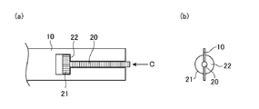
- FIG. 7 is a view showing a state in which the thin plate male screw 20 shown in FIG. 5 is inserted from the “thickness” direction into the substantially T-shaped notch 11 of the thin plate 10 shown in FIG. (A) is the top view seen from the plane which consists of a "width” direction and a "length” direction
- FIG.7 (b) is the side view which looked at Fig.7 (a) from the arrow C direction of a figure.
- the diameter of the shaft portion of the thin plate male screw 20 is larger than the “thickness” of the thin plate 10
- the diameter of the head 21 of the thin plate male screw 20 is “thickness” of the thin plate 10. Therefore, even when the thin plate male screw 20 is inserted into the substantially T-shaped notch 11 of the thin plate 10, the head 21 can be turned.
- FIG. 8 is a view showing a state in which the thin plate 10 in which the thin plate male screw 20 is inserted into the substantially T-shaped cutout 11 of the thin plate 10 is inserted into the slit 31 of the support column 30 and fixed as shown in FIG. is there.
- the thin plate 10 is inserted into the slit 31 of the support column 30, and the "thickness" of the notch 11 in which the seat surface 22 of the thin plate male screw 20 is substantially T-shaped is set in the direction of the support column 30 (Fig. 8).
- the head 21 of the thin plate male screw 20 is rotated so as to press in the direction of the arrow D, and the thin plate male screw 20 is screwed onto the female screw 32 in the slit 31 so that the position of the thin plate 10 can be adjusted. It can be fixed to the column 30.
- the slit 31 of the support column 30 has been described as a slit that is not open in the longitudinal direction.
- the end portion of the support column (the lower portion of FIG. 6A)
- the slit may be an open end.
- the light-receiving part 4 shall be fixed by the three thin plates 10, and the three support
- the number of pairs of the thin plate 10 and the support column 30 is not limited.
- the amount is not so much.
- the position while supporting the light receiving unit 4 as shown in FIG. What is provided with a pair of thin plates 10 and struts 30 is optimal.
- the thin plate male screw is used to fix the position while easily adjusting the position. can do.
- Embodiment 3 In the third embodiment of the present invention, as in the second embodiment, a case where a thin plate fixing method for fixing a thin plate to a support is applied to the oil film detection apparatus shown in FIGS. 1 and 3 will be described as an example.
- the thin plate 10 and the thin plate male screw 20 are the same as those shown in FIGS. 4, 5, and 7 in the second embodiment, but are replaced with the support 30 shown in FIG. Assume that the column 30 shown in FIG. 10 is used.
- a fixing screw 40 as shown in FIG. 9 is used.
- the support column 30 is connected to the slit 31 and the thin plate male screw 20.
- the through hole 34 for the fixing screw and the female screw 35 for the fixing screw are located at the position having the slit 31 and not interfering with the thin plate 10 when the thin plate 10 is inserted into the slit 31. It is to be prepared.
- FIG. 10A shows the column 30 in the “width” direction and “thickness” of the thin plate 10 when the thin plate 10 is inserted.
- FIG. 10 (b) is a perspective view thereof
- FIG. 10 (c) is an enlarged view of a main part of FIG. 10 (b) (an enlarged view of a female screw 32 portion, and a fixing screw). It is an enlarged view of the through-hole 34 and the internal thread 35 part for fixing screws.
- the end portion of the support column 30 (the lower portion of FIG. 10A) is a slit that is an open end will be described. However, as in the second embodiment, the open portion is opened. A slit that is not an end may be used.
- FIG. 11 shows a state in which the thin plate 10 in which the thin plate male screw 20 is inserted into the substantially T-shaped notch 11 of the thin plate 10 as shown in FIG. 7 is inserted into the slit 31 of the support column 30 shown in FIG. FIG.
- the thin plate 10 is inserted into the slit 31 of the support 30, and the seat surface 22 of the thin plate male screw 20 has a substantially T-shaped notch 11 'thickness' in the direction of the support 30 (see FIG. 11).
- the head 21 of the thin plate male screw 20 is turned so as to press in the direction of the arrow E, and the thin plate male screw 20 is screwed into the female screw 32 in the slit 31 so that the position of the thin plate 10 can be adjusted. It can be fixed to the column 30.
- the fixing screw 40 shown in FIG. 9 is inserted into the through hole 34 for the fixing screw provided in the column 30 (in the direction of arrow F in FIG. 11), and the seating surface of the fixing screw 40 presses the column 30.
- the fixing screw 40 is screwed into the fixing screw female screw 35 through the fixing screw through hole 34, and the thin plate 10 after position adjustment is attached to the column 30. It can be fixed securely.
- the through hole 34 for the fixing screw and the female screw 35 for the fixing screw are separated by the slit 31 as shown in FIG. 10, but both are sized so that the fixing screw 40 can be inserted.
- the fixing screw through-hole 34 is a simple hole in which no female screw is formed. Therefore, when the fixing screw 40 is inserted into the fixing screw through-hole 34, the tip of the fixing screw 40 is inserted. Can be easily inserted up to a position exceeding the slit 31. Then, by turning the head 41 of the fixing screw 40, the fixing screw 40 is screwed into the fixing screw female screw 35 through the fixing screw through hole 34, and the seating surface of the fixing screw 40 is the support 30. The head 41 can be reliably fixed by turning it to the position where it is pressed.
- the three positions provided in the detector W are used to finely adjust the position of the light receiving unit 4 of the oil film detection device.
- the position of the thin plate 10 is adjusted by rotating the thin plate male screw 20 with respect to each of the columns 30, and the position of the light receiving unit 4 is determined by the position adjustment of the three thin plates 10.
- each thin plate 10 can be more securely fixed to the corresponding column 30.
- the light receiving unit 4 can also be securely fixed at the position adjusted.
- the fixing screw female screw 35 on the support column 30, it is possible to securely fix the thin plate 10 without using a separate part such as a nut, and the site where the oil film detector is installed. Even when it is necessary to adjust the position of the thin plate 10, the position of the thin plate 10 and the light receiving unit 4 can be easily adjusted and securely fixed without worrying about losing parts such as nuts.
- the thin plate after the position adjustment and fixing to the support column is more reliable. Can be fixed to.
- the column 30 is described as a columnar column, but it goes without saying that it may be a column having another shape such as a square column or a hexagonal column.
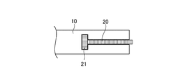
- the substantially T-shaped notch 11 provided in the thin plate 10 has a portion into which the head 21 of the thin plate male screw 20 is inserted as shown in FIG. Although described as having a length in the “length” direction larger than the head 21, as shown in FIGS. 12 and 13, a substantially T-shape having substantially the same size as the head 21 of the thin plate male screw 20.
- the notch 11 may be used.
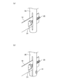
- FIGS. 8 and 11 a diagram showing a state in which the thin plate 10 is inserted and fixed into the slit 31 of the support column 30 is shown in FIGS. It becomes like b).
- the seat surface 22 of the thin plate male screw 20 immediately presses the “thickness” of the substantially T-shaped notch 11 in the direction of the column 30. Therefore, the responsiveness at the time of position adjustment is improved.
- W 100 detector, 1,110 light source / scanning part, 2,120 concave mirror, 3 through-hole, 4,140 light receiving part, 5,150 receiving part, 6,160 window, 7 exit window, 9a, 9b, 190 water surface (Detection target surface) 10 thin plate, 11 substantially T-shaped notch, 20 thin plate male screw, 21 head of thin plate male screw 20, 22 seat surface of thin plate male screw 20, 30 strut, 31 strut 30 Slit, 32 female screw, 34 through hole for fixing screw, 35 female screw for fixing screw, 40 fixing screw, 41 head of fixing screw 40.
Landscapes
- Physics & Mathematics (AREA)
- Health & Medical Sciences (AREA)
- Life Sciences & Earth Sciences (AREA)
- Chemical & Material Sciences (AREA)
- Analytical Chemistry (AREA)
- Biochemistry (AREA)
- General Health & Medical Sciences (AREA)
- General Physics & Mathematics (AREA)
- Immunology (AREA)
- Pathology (AREA)
- Mathematical Physics (AREA)
- Investigating Or Analysing Materials By Optical Means (AREA)
Description
この発明は、浄水場や河川、湖沼等の水面(検出対象面)に存在する油膜を検出するための油膜検出装置に関するものである。
従来より、例えば、浄水場や河川、湖沼等に油膜が存在している場合には、取水の中止等の措置を行う必要があったり、工場の処理水に油膜が存在している場合には、処理工程の点検や排水の中止等の措置が必要であったりすることから、水面の油膜検出が行われている。この油膜検出装置としては、種々の方式のものが知られているが、油膜による光の反射率が水面による光の反射率よりも高いことに着目し、水面からの反射光の強度を測定して油膜を検出する油膜検出装置が知られている。
例えば、特許文献1には、光源から水面等の検出対象面にレーザ光を照射し、検出対象面からの反射光を受光して検出対象面に存在する油膜を検出する油膜検出装置において、X方向駆動電圧、Y方向駆動電圧を印加してそれぞれ発生させた変位によりレーザ光を2次元的に走査し、検出対象面におけるレーザ光の照射範囲として所望の平面を形成する2次元走査部を備えた油膜検出装置が開示されている。
また、特許文献2には、水面に向けて光を照射する発光部と、水面での反射光を受光する受光部と、受光部で受光した反射光量から水面上の油膜の有無を検出する油膜検出装置であって、発光部から発せられた光を発散させ発散ビームとして水面に照射する凹レンズと、凹レンズと水面との間に設置され、発散ビームの水面での反射光が入射したとき、その入射光を入射経路と略同じ経路で水面に向けて反射する回帰性のリフレクタとを備え、リフレクタで反射された光が、水面で反射し収束ビームとなって凹レンズを透過して受光部で受光される油膜検出装置が開示されている。
一方、油膜検出装置には、フロート式と固定式とがあり、フロート式の場合には、水面に浮かべて測定するものであるため、水位の変動に常に追従することができる。しかし、例えば特許文献1や特許文献2に開示されているような固定式の場合には、水面と検出器との距離が水位の変動に応じて変化する。このため、水面に向かって略鉛直方向に光を照射するように構成して、常に水面(検出対象面)の所望の範囲に光を照射することができるようにするなどして、水位の変動に応じて変化する光学系の位置関係に起因する問題の解決は図られているが、豪雨等により水面が異常に上昇すると、平常時の水面から比較的近い位置に設置されている検出器が水没してしまうおそれがある。そこで、水面から十分に距離を離して設置しても測定することができ、かつ、精度良く油膜を検出することができる油膜検出装置が望まれている。
しかしながら、例えば特許文献1のような従来の油膜検出装置の検出器は、光学系の結露防止や電気部の保護のために、図15に示すように、光源・走査部110、凹面鏡120、受光部140等を収容部150に収容し、窓160により水密に封じるように構成されている。そして、この検出器100の窓160は、水平面に対して所定角度傾斜して検出器100に取り付けられている。これは、光源110からの出射光が、窓160の天面および底面で反射して迷光となることを防ぐためのものであり、例えば、光源110から出射され窓160の天面で反射した光が凹面鏡120へ入射したとしても、その反射光はGの地点へと導かれ、受光部140には入射しないようになっている。しかしながら、水平面に対して傾斜する窓160により収容部150を水密に封じるための構造の設計・加工は複雑であり、組み立ての作業性も悪く、コストも嵩むという課題があった。
また、従来の油膜検出装置は、例えば図15や特許文献1の図6、図8等に示す凹面鏡120、40のように焦点位置がシフトしているいわゆる軸外し放物面鏡等を使用して、検出対象面からの反射光が受光部により遮られないようにして、少ない面積であっても効率的に集光することができるようにしているが、さらに精度良く油膜を検出するためには、凹面鏡を大きくする必要がある。しかし、大型の軸外し放物面鏡を製作するには大きなブロックから削り出さなければならないためコストが嵩み、また、凹面鏡を大きくすると検出器の口径も大きくなるため、上述のような傾斜した窓を組み込むと、検出器の垂直方向の寸法も大きくなり検出器が大型化する、という課題があった。
一方、例えば特許文献2のような従来の油膜検出装置は、水面での反射光を回帰性リフレクタで反射させて光を往復させて検出するものであるため、反射光の減衰量が大きく、水面との距離が離れると受光部に届く光量が極めて小さくなり、感度良く測定することができなくなってしまう、という課題があった。
さらに、例えば図15に示したような従来の油膜検出装置においては、光学系の位置関係に応じて、センサの位置を微調整する必要が生じる。
しかしながら、水面からの反射光を遮ることのないようにしつつ、位置調整する機構を備えることは困難である、という課題があった。
しかしながら、水面からの反射光を遮ることのないようにしつつ、位置調整する機構を備えることは困難である、という課題があった。
この発明は、上記のような課題を解決するためになされたものであり、水面(検出対象面)との距離が離れている場合であっても、確実に精度良く油膜を検出することができる油膜検出装置を提供することを目的とする。
上記目的を達成するために、この発明は、水平方向に広がる検出対象面に対して略平行に設置される検出器内に、少なくとも光源と凹面鏡と受光部とを収容する収容部と、該収容部を水密に封じる窓とを備え、前記光源から前記検出対象面に向けて光を照射し、前記検出対象面からの反射光を前記凹面鏡により集光して前記受光部に受光させることにより、前記検出対象面に存在する油膜を検出する油膜検出装置において、前記光源は、前記凹面鏡の上方に配置され、略鉛直方向に光を出射し、前記凹面鏡は、当該凹面鏡の光軸が水平方向に対して直交するように配置されるとともに、当該凹面鏡の光軸よりずれた位置に、前記光源からの出射光を通過させる貫通孔を有しており、前記受光部は、前記凹面鏡の光軸上の焦点位置に配置されることを特徴とする。
また、前記窓は、前記検出器の水平断面に対して平行に配設されるとともに、当該窓の一部に前記出射光を透過させる出射窓が水平面に対して所定角度傾斜して設けられていることを特徴とする。
さらに、前記受光部は、前記光源から照射された光軸の方向に「幅」を有し、前記光軸に対して直行する方向に前記「幅」より長い「長さ」と前記「幅」より短い「厚み」とを有する少なくとも2以上の薄板により保持され、前記薄板は、前記「幅」方向および「長さ」方向からなる平面に、頭部を有する薄板用おねじを前記「厚み」方向から挿入可能な略T字状の切り欠きを備え、前記検出器は、前記それぞれの薄板に対応する支柱を備え、前記支柱は、長尺方向に前記薄板の「幅」よりも長いスリットを備えるとともに、該スリット内に前記薄板用おねじと螺合可能なめねじを備えるものであり、前記薄板を前記対応する支柱のスリット内に挿入し、前記薄板用おねじをその座面が前記略T字状の切り欠きの「厚み」を前記支柱の方向に押圧するように前記スリット内のめねじに螺合させることにより、前記薄板を位置調整可能に前記対応する支柱に固定されていることを特徴とする。
この発明によれば、検出対象面に向けて光源から略鉛直方向に光が照射され、検出対象面から反射した光を集光する凹面鏡がその光軸が水平方向に直交するように配置され、かつ、受光部が凹面鏡の光軸上の焦点位置に配置される(すなわち、軸外し凹面鏡ではない凹面鏡を用いる)ことにより、水面(検出対象面)までの距離が離れている場合であっても、確実に精度良く油膜を検出することができる。また、検出器内の収容部を水密に封じる窓は、検出器の水平断面に対して平行に配設されるため、収容部を水密に封じる構造は一般的なものでよく、加工が容易で組み立ての作業性も良い油膜検出装置を提供することができる。さらに、窓の一部に、出射光を透過させる出射窓が水平面に対して所定角度傾斜して設けられていることにより、検出器の大型化を回避しつつ精度良く油膜を検出することができる油膜検出装置を提供することができる。
また、受光部を薄板により保持し、その薄板を支柱に固定する際に、薄板用おねじを用いて、簡単に位置調整しながら固定することができるようにしたので、水面からの反射光を遮ることのないようにしつつ、受光部の位置調整を容易にすることができる。
また、受光部を薄板により保持し、その薄板を支柱に固定する際に、薄板用おねじを用いて、簡単に位置調整しながら固定することができるようにしたので、水面からの反射光を遮ることのないようにしつつ、受光部の位置調整を容易にすることができる。
以下、この発明の実施の形態について、図面を参照しながら詳細に説明する。
実施の形態1.
この発明における油膜検出装置は、レーザ光源を用いた光学式(光反射法)によるものである。これは、水面と油膜との光の反射率の差を利用した方法である。一般的に、水面による光の反射率は約2%、油膜による光の反射率は3~4%の間を推移すると言われており、油膜からの反射光の方が1.5~2倍くらい強い。そこで、一定の強さの光を水面に当てて、反射光の強さ(受光量)を検出器により測定し、変換器により各種演算処理を行うことにより、油膜の有無を検出・判別することができる。そして、油膜を検出すると警報を出力するようになっており、これにより、取水の中止等の判断が行われる。
実施の形態1.
この発明における油膜検出装置は、レーザ光源を用いた光学式(光反射法)によるものである。これは、水面と油膜との光の反射率の差を利用した方法である。一般的に、水面による光の反射率は約2%、油膜による光の反射率は3~4%の間を推移すると言われており、油膜からの反射光の方が1.5~2倍くらい強い。そこで、一定の強さの光を水面に当てて、反射光の強さ(受光量)を検出器により測定し、変換器により各種演算処理を行うことにより、油膜の有無を検出・判別することができる。そして、油膜を検出すると警報を出力するようになっており、これにより、取水の中止等の判断が行われる。
なお、レーザ光源を用いる光学式の油膜検出装置は、ファイバー式や静電容量式のような接触式ではない(非接触式である)というメリットだけではなく、他の光源(例えば、LED光源等)に比べて、光量が大きく、直線性も良いので、水面までの距離が離れている場合であっても反射光を検出することができる、というメリットがある。
図1は、この発明の実施の形態1における油膜検出装置の検出器の構成例および作用を模式的に示す概略断面図である。この実施の形態1における油膜検出装置は、図1に示すような検出器Wと、図示しない変換器とから構成されている。検出器Wと変換器とは、ケーブルにより接続され、検出器Wで測定された反射光の強さ(受光量)に基づく信号が変換器に送られるようになっている。また、変換器は、各種演算処理を行い油膜の有無を検出・判別し、油膜を検出すると警報を出力したり、表示部に状態を表示したりすることができるようになっている。さらに、変換器は、検出器Wを制御する制御信号を出力することもできる。
検出器Wは、光源・走査部1、凹面鏡2および受光部4を収容する収容部5と、収容部5を水密に封じる窓6とを備え、検出対象面である水面9a,9b上に、水面9a,9bと略平行(水平方向に対して略平行)になるように設置される。なお、検出器Wの筐体は、光を透過しない材質で形成されており、窓6(出射窓7を含む)以外から収容部5内へ光が入り込むことはない。
光源・走査部1は、レーザ光源と、その光源を走査する走査部とを備え、レーザ光を走査することにより、検出対象面におけるレーザ光の照射範囲として所望の平面を形成することができるようになっている。ここで、レーザ光を走査するための構成としては、振動素子などを使用すればよいが、この走査する機構については公知の技術であるため、ここでは詳しい説明を省略する。そして、光源・走査部1は、凹面鏡2の上方に配置され、出射されたレーザ光が水面(検出対象面)9a,9bに向けて略鉛直方向に照射されるように取り付けられている。
また、この実施の形態1における油膜検出装置で使用される凹面鏡2は、その反射面により集光した光が焦点を結ぶ焦点位置が、反射面の中心軸上にあるもの、すなわち、光軸Zと中心軸とが一致するもの(いわゆる軸外し凹面鏡ではないもの)である。また、凹面鏡2は、光軸Zが水平方向に対して直交するように配置されるとともに、光軸Zよりずれた位置に貫通孔3を有しており、光源・走査部1から出射され貫通孔3を通過して水面9a,9bにより反射してきた光を、反射面により集光して光軸Z上(検出器Wの略中心軸上)の焦点位置に配置された受光部4に入射させることができるようになっている。この凹面鏡2は、いわゆる軸外し凹面鏡ではないものであればよく、通常の放物面鏡、楕円面鏡などを用いることができる。また、貫通孔3の大きさは、光源・走査部1により出射され走査される光が透過する範囲と同じかやや大きい程度であることが好ましい。なお、水面9a,9bからの反射光を効率的に検出する上で、貫通孔3の位置は凹面鏡2の光軸Z(凹面鏡2の中心部)に近い方が好ましいが、貫通孔3を通過した光が直接受光部4に入射しないような位置にする必要がある。
この実施の形態1における油膜検出装置の窓6は、検出器W内の収容部5を水密に封じるように検出器Wの水平断面に対して平行に取り付けられている。また、窓6は、その一部に、水平面に対して所定角度傾斜した出射窓7を有している。
出射窓7は、光源・走査部1の鉛直方向に位置し、光源から出射された光を透過させるようになっている。出射窓7の傾斜角度は、光源から出射され出射窓7の天面および底面で反射した光が、(1)凹面鏡2から外れた位置(例えばB地点)に導かれるような角度であること、(2)凹面鏡2に入射してさらに反射したとしても、受光部4に入射せず、かつ、窓6(出射窓7部分を含む)を介して検出器Wの外部に出ないような角度であること、のいずれかを満たすことを条件に、凹面鏡2の曲率、受光部4の大きさ、出射窓7の位置等に応じて決定することができる。また、出射窓7の大きさは、光源・走査部1により出射され走査される光が透過する範囲と同じかやや大きい程度であることが好ましい。
なお、窓6および出射窓7は、光源から出射される光および反射光を透過させるものであればよく、加工のし易さ、重量、コスト等の点から、アクリルなどの透明樹脂により形成することが好ましいが、材質に限定はなく、ガラス等を用いることもできる。
出射窓7は、光源・走査部1の鉛直方向に位置し、光源から出射された光を透過させるようになっている。出射窓7の傾斜角度は、光源から出射され出射窓7の天面および底面で反射した光が、(1)凹面鏡2から外れた位置(例えばB地点)に導かれるような角度であること、(2)凹面鏡2に入射してさらに反射したとしても、受光部4に入射せず、かつ、窓6(出射窓7部分を含む)を介して検出器Wの外部に出ないような角度であること、のいずれかを満たすことを条件に、凹面鏡2の曲率、受光部4の大きさ、出射窓7の位置等に応じて決定することができる。また、出射窓7の大きさは、光源・走査部1により出射され走査される光が透過する範囲と同じかやや大きい程度であることが好ましい。
なお、窓6および出射窓7は、光源から出射される光および反射光を透過させるものであればよく、加工のし易さ、重量、コスト等の点から、アクリルなどの透明樹脂により形成することが好ましいが、材質に限定はなく、ガラス等を用いることもできる。
図2は、図1に示す油膜検出装置の検出器を下面(水面)側から見た底面図であり、受光部4と、出射窓7との位置関係を示す図である。前述のとおり、貫通孔3の位置は凹面鏡2の光軸Z(凹面鏡2の中心部)に近い方が好ましいが、貫通孔3を通過した光が直接受光部4に入射しないようにする必要がある。したがって、出射窓7も受光部4とは重ならない位置に設けられており、出射窓7へ向かう光が受光部4により遮られることはないようになっている。すなわち、光軸Z(凹面鏡2の中心部)から少しだけずれた位置に、光軸と平行して、光源・走査部1、貫通孔3および出射窓7が配置されている。
なお、薄板10は、受光部4を凹面鏡2の光軸Z上の焦点位置に固定するために検出器Wへ取り付けられているものであり、受光部4の位置を微調整することができるようになっているが、図1においては図示を省略している。
なお、薄板10は、受光部4を凹面鏡2の光軸Z上の焦点位置に固定するために検出器Wへ取り付けられているものであり、受光部4の位置を微調整することができるようになっているが、図1においては図示を省略している。
次に、図1を参照しながら、この実施の形態における油膜検出装置の動作および作用を説明する。
光源・走査部1により出射され走査された光は、破線に示すような広がりをもった範囲で略鉛直方向に照射される。この光は、窓6の一部に設けられた出射窓7内を透過するようになっている。出射窓7は所定角度傾斜しているため、その天面および底面で反射した光は凹面鏡2から外れたB地点に導かれるようになっており、油膜検出の支障となる迷光となることはない。
光源・走査部1により出射され走査された光は、破線に示すような広がりをもった範囲で略鉛直方向に照射される。この光は、窓6の一部に設けられた出射窓7内を透過するようになっている。出射窓7は所定角度傾斜しているため、その天面および底面で反射した光は凹面鏡2から外れたB地点に導かれるようになっており、油膜検出の支障となる迷光となることはない。
出射窓7を透過した光は水面9a,9bで反射し、窓6を透過して凹面鏡2を介して受光部4に到達する。図1の破線は、光の照射範囲の外縁において、水面9a,9bが完全な平面であるとした場合の光路を表しているが、実際の測定においては、水面9a,9bには揺らぎ(波)があるため、反射光が常に一定の光路で凹面鏡2に戻るということはなく、凹面鏡2の反射面が広いほど、油膜を検出する可能性が高まる。
また、水面9aは、水位が高くなっているときの状態を示すものであり、水面9bは、水位が低いときの状態を示すものである。光源・走査部1から出射された光は、略鉛直方向に照射されるため、水位が変動しても、水面9a,9bに光が照射される平面が常に形成され、表面反射した光を凹面鏡2で捉えることができる。
なお、凹面鏡2として放物面鏡を用いた場合、光軸に対して平行な光の全てが焦点に集光されるわけであるが、受光部4にある程度の面積(受光面の広さ)をもたせておくことにより、完全な平行光でない反射光も集光することができる。
受光部4で検出した光の強さ(受光量)に基づく信号は、変換器に送られて各種演算処理され、油膜の有無の判断に用いられる。そして、油膜を検出した場合には、警報信号を出力する等の処理が行われる。
また、水面9aは、水位が高くなっているときの状態を示すものであり、水面9bは、水位が低いときの状態を示すものである。光源・走査部1から出射された光は、略鉛直方向に照射されるため、水位が変動しても、水面9a,9bに光が照射される平面が常に形成され、表面反射した光を凹面鏡2で捉えることができる。
なお、凹面鏡2として放物面鏡を用いた場合、光軸に対して平行な光の全てが焦点に集光されるわけであるが、受光部4にある程度の面積(受光面の広さ)をもたせておくことにより、完全な平行光でない反射光も集光することができる。
受光部4で検出した光の強さ(受光量)に基づく信号は、変換器に送られて各種演算処理され、油膜の有無の判断に用いられる。そして、油膜を検出した場合には、警報信号を出力する等の処理が行われる。
このように、光源・走査部1、貫通孔3および出射窓7を凹面鏡2の中心よりずれた位置に光軸と平行して配置することにより、受光部4を凹面鏡2の光軸Z上の焦点位置に配置しても、光源・走査部1から出射されるレーザ光を、受光部4が遮ってしまうことがなく、水面(検出対象面)9a,9bからの反射光を効率よく集光することができる。
また、光源・走査部1からの光は略鉛直方向に出射されるため、検出器Wと検出対象面との距離が変わっても、すなわち水面の高さが変動しても(図1の水面9a、水面9b参照)、検出対象面に確実に光を照射することができ、その検出対象面からの反射光を確実に集めることができる。
また、この発明の実施の形態1における油膜検出装置では、検出器W内の収容部5を水密に封じる窓6を、検出器Wの水平断面に対して平行に配設するようにしたため、収容部5を水密に封じる構造は一般的なものでよく、加工が容易で組み立ての作業性も良い。
出射窓7は、光源・走査部1から出射されたレーザ光が、窓6の天面および底面で反射した光が迷光となって受光部4で検出されてしまうことを防ぐため、光軸に対して斜め、すなわち、水平面に対して所定角度傾斜して設けられている。ここで、図1に示すこの実施の形態1における油膜検出装置において、図15に示す従来の油膜検出装置と同様に、1枚の窓を斜めに取り付けたとすると、上下方向の寸法もかなり大きくなってしまう。そこで、この発明の実施の形態1においては、窓6は検出器Wの水平断面に対して平行に配設し、光源・走査部1から出射されたレーザ光が透過する出射窓7のみを光軸に対して斜めに(水平面に対して所定角度傾斜して)設置するように構成した。
その結果、図15に示す従来の油膜検出装置と同様に、この発明の実施の形態における油膜検出装置においても、光源・走査部1から出射されたレーザ光が窓6で反射して迷光となることが防止され、精度良く油膜を検出することができる。
また、従来では受光部を検出器の端に設置する必要があり、効率よく集光できる受光部の位置を調整することは手間がかかる作業であったが、いわゆる軸外し凹面鏡ではない凹面鏡2を使用する場合には中心に光が集まるため、受光部4を中心に設置すれば必然的に効率よく集光することができる。さらに、凹面鏡2は、いわゆる軸外し凹面鏡(凹面鏡120)に比べて安価で作りやすいというメリットもある。
また、検出器W内の収容部5を水密に封じる窓6を、検出器Wの水平断面に対して平行に配設するようにし、光源・走査部1から出射されたレーザ光が透過する位置であるごく一部分のみを光軸に対して斜めに形成された出射窓7としたので、従来の凹面鏡よりも大きい凹面鏡を使用したとしても、高さ方向の大きさは従来と同程度にすることができ、スペース効率がよい。
以上のように、この発明の実施の形態1における油膜検出装置によれば、コストアップや大型化を回避しつつ、測定精度や組み立ての作業性を向上させることができ、従来の油膜検出装置では、水面(検出対象面)9aまでの距離が例えば5m前後までしか確実には油膜が検出できなかったとすると、この実施の形態における油膜検出装置によれば、水面(検出対象面)9bまでの距離が例えば10m前後であっても油膜を検出することができる。
実施の形態2.
図3は、図1に示す油膜検出装置の検出器のA-A断面図であり、受光部4を検出器Wの略中心軸(光軸Z)上に固定するために、受光部4が薄板10を介して検出器Wの支柱30に固定されている状態を示す図である。
なお、受光部4を固定する薄板10および検出器Wの支柱30は、図1においては図示を省略している。
図3は、図1に示す油膜検出装置の検出器のA-A断面図であり、受光部4を検出器Wの略中心軸(光軸Z)上に固定するために、受光部4が薄板10を介して検出器Wの支柱30に固定されている状態を示す図である。
なお、受光部4を固定する薄板10および検出器Wの支柱30は、図1においては図示を省略している。
ここで、この受光部4を固定する薄板10が、光源・走査部1から発射されたレーザ光や水面(検出対象面)9a,9bから反射された反射光をできるだけ遮ることのないように、薄板10の厚みはできる限り薄いことが望ましい。しかしながら、図1に示す油膜検出装置のような通常の大きさの装置では、受光部4も薄板10もある程度の大きさおよび重量を備えるものとなるため、薄板10には強度も必要とされる。
また、受光部4は凹面鏡2の光軸Z上(検出器Wの略中心軸上)の焦点位置に配置しなければならないが、装置ごとの個体差や装置の設置状態に応じて微調整をすることが必要である。
その結果、薄板10は、極力細い断面形状(薄い板)であり、かつ、受光部4の位置調整を行うことが可能な機構を備えていることが必要である。
その結果、薄板10は、極力細い断面形状(薄い板)であり、かつ、受光部4の位置調整を行うことが可能な機構を備えていることが必要である。
そこで、この実施の形態2の油膜検出装置においては、図3に示すように、受光部4を3枚の薄板10により固定するものとし、それぞれの薄板10に対応する支柱30も3つ備えるものとする。また、それぞれの薄板10を対応する支柱30に固定する方法としては、以下に説明するとおり、図4~図8に示すような薄板固定方法を用いることとする。
薄板10は、図4に示すように、光源・走査部1から照射された光軸の方向に「幅」を有し、その光軸に対して直交する方向のうち受光部4と検出器Wの支柱30とを結ぶ方向に「幅」より長い「長さ」と、同じく光軸の方向に垂直な方向のうちもう一方に「幅」より短い「厚み」とを有するものである。
この薄板10は、「長さ」方向の一端(図示せず)が受光部4に接続されており、他端が検出器Wの支柱30に固定されるものであり、図4(a)は、薄板10の他端側(検出器Wの支柱30に固定される側)を「幅」方向および「長さ」方向からなる平面から見た平面図、図4(b)はその斜視図である。
そして、図4に示すとおり、薄板10の他端側(検出器Wの支柱に固定される側)には、「幅」方向および「長さ」方向からなる平面に、頭部21を有する薄板用おねじ20(図5参照)を「厚み」方向から挿入可能な略T字状の切り欠き11が備えられている。
そして、図4に示すとおり、薄板10の他端側(検出器Wの支柱に固定される側)には、「幅」方向および「長さ」方向からなる平面に、頭部21を有する薄板用おねじ20(図5参照)を「厚み」方向から挿入可能な略T字状の切り欠き11が備えられている。
また、検出器Wの支柱30は、図6に示すように、薄板10の「幅」よりも長いスリット31を長尺方向に備えるとともに、このスリット31内に薄板用おねじ20と螺合可能なめねじ32を備えている。
そして、この支柱30のスリット31内に薄板10が挿入されるものであり、図6(a)は、支柱30を、薄板10が支柱30に挿入された場合の薄板10の「幅」方向および「厚み」方向からなる平面から見た平面図、図6(b)はその斜視図、図6(c)は図6(b)の要部拡大図(めねじ32部分の拡大図)である。
そして、この支柱30のスリット31内に薄板10が挿入されるものであり、図6(a)は、支柱30を、薄板10が支柱30に挿入された場合の薄板10の「幅」方向および「厚み」方向からなる平面から見た平面図、図6(b)はその斜視図、図6(c)は図6(b)の要部拡大図(めねじ32部分の拡大図)である。
図7は、図4(a)に示す薄板10の略T字状の切り欠き11に、図5に示す薄板用おねじ20を「厚み」方向から挿入した状態を示す図であり、図7(a)は「幅」方向および「長さ」方向からなる平面から見た平面図、図7(b)は図7(a)を図の矢印C方向から見た側面図である。この図に示すように、薄板用おねじ20の軸部の径は、薄板10の「厚み」よりも大きく、また、薄板用おねじ20の頭部21の径は、薄板10の「厚み」に比べてかなり大きいため、薄板用おねじ20を薄板10の略T字状の切り欠き11に挿入した状態であっても、頭部21を回すことが可能である。
図8は、図7に示すように薄板用おねじ20を薄板10の略T字状の切り欠き11に挿入した薄板10を、支柱30のスリット31に挿入して固定した状態を示す図である。この図に示すように、薄板10を支柱30のスリット31に挿入し、薄板用おねじ20の座面22が略T字状の切り欠き11の「厚み」を支柱30の方向(図8の矢印Dの方向)に押圧するように薄板用おねじ20の頭部21を回して、薄板用おねじ20をスリット31内のめねじ32に螺合させることにより、薄板10を位置調整可能に支柱30に固定することができる。
このように、薄板用おねじ20と螺合するめねじ32をスリット31内に設けたことにより、ナットなどの別部品を用いることなく、薄板10の位置を微調整することが可能であり、油膜検出装置が設置された現場において位置調整を行う必要が生じた場合であっても、ナットなどの部品をなくす心配もなく、また、工具などを使用することなく簡単に薄板10および受光部4の位置調整を行うことができる。
なお、この実施の形態2では、支柱30のスリット31が、長尺方向にいずれも開放されていないスリットであるものとして説明したが、支柱の端部(図6(a)の下方部分)が開放端となったスリットであっても構わない。
また、この実施の形態2における油膜検出装置では、図3に示すように、受光部4を3枚の薄板10により固定するものとし、それぞれの薄板10に対応する支柱30も3つ備えるものとしたが、受光部4を支持することができ、かつ、受光部4の位置調整を行うことが可能であれば、薄板10および支柱30の組はいくつであっても構わない。ただし、できるだけレーザ光や反射光を遮ることがないようにするためにはあまり多くない方が望ましく、かつ、受光部4を支持しつつ位置調整も行うためには、図3に示すように3組の薄板10および支柱30を備えるものが最適である。
以上のように、この発明の実施の形態2における薄板固定方法を用いた油膜検出装置によれば、薄板を支柱に固定する際に、薄板用おねじを用いて、簡単に位置調整しながら固定することができる。
実施の形態3.
この発明の実施の形態3においても、実施の形態2と同様に、支柱に薄板を固定する薄板固定方法を、図1および図3に示す油膜検出装置に適用した場合を例に説明する。
この発明の実施の形態3では、薄板10および薄板用おねじ20については、実施の形態2における図4,図5,図7に示すものと同じであるが、図6に示す支柱30に代えて、図10に示す支柱30を用いるものとする。
この発明の実施の形態3においても、実施の形態2と同様に、支柱に薄板を固定する薄板固定方法を、図1および図3に示す油膜検出装置に適用した場合を例に説明する。
この発明の実施の形態3では、薄板10および薄板用おねじ20については、実施の形態2における図4,図5,図7に示すものと同じであるが、図6に示す支柱30に代えて、図10に示す支柱30を用いるものとする。
この際、薄板10の支柱30に対する固定をより確実にするために、図9に示すような固定ねじ40を用い、図10に示すように、支柱30が、スリット31および薄板用おねじ20と螺合するめねじ32だけでなく、スリット31を有する部分であって薄板10をスリット31に挿入した場合に薄板10と干渉しない位置に、固定ねじ用の貫通孔34および固定ねじ用めねじ35も備えるものである。
そして、この支柱30のスリット31内に薄板10が挿入されるものであり、図10(a)は、支柱30を、薄板10が挿入された場合の薄板10の「幅」方向および「厚み」方向からなる平面から見た平面図、図10(b)はその斜視図、図10(c)は図10(b)の要部拡大図(めねじ32部分の拡大図と、固定ねじ用の貫通孔34および固定ねじ用めねじ35部分の拡大図)である。
なお、この実施の形態3では、支柱30の端部(図10(a)の下方部分)が開放端となったスリットであるものを例に説明するが、実施の形態2と同様に、開放端となっていないスリットであっても構わない。
なお、この実施の形態3では、支柱30の端部(図10(a)の下方部分)が開放端となったスリットであるものを例に説明するが、実施の形態2と同様に、開放端となっていないスリットであっても構わない。
図11は、図7に示すように薄板用おねじ20を薄板10の略T字状の切り欠き11に挿入した薄板10を、図10に示す支柱30のスリット31に挿入して固定した状態を示す図である。この図に示すように、薄板10を支柱30のスリット31に挿入し、薄板用おねじ20の座面22が略T字状の切り欠き11の「厚み」を支柱30の方向(図11の矢印Eの方向)に押圧するように薄板用おねじ20の頭部21を回して、薄板用おねじ20をスリット31内のめねじ32に螺合させることにより、薄板10を位置調整可能に支柱30に固定することができる。
そしてさらに、図9に示す固定ねじ40を、支柱30に設けられた固定ねじ用の貫通孔34に(図11の矢印Fの方向に)挿入し、固定ねじ40の座面が支柱30を押圧するように固定ねじ40の頭部41を回すことにより、固定ねじ40を固定ねじ用の貫通孔34を介して固定ねじ用めねじ35に螺合させ、位置調整後の薄板10を支柱30に確実に固定することができる。
なお、固定ねじ用の貫通孔34および固定ねじ用めねじ35は、図10に示すように、スリット31によって分かれているが、いずれも固定ねじ40が挿入可能な大きさである。この際、固定ねじ用の貫通孔34は、その内部にめねじは形成されていない単なる孔であるため、固定ねじ40を固定ねじ用の貫通孔34に挿入した場合に、固定ねじ40の先端がスリット31を超える位置までは容易に挿入できる。そして、その後は固定ねじ40の頭部41を回すことにより、固定ねじ40を固定ねじ用の貫通孔34を介して固定ねじ用めねじ35に螺合させ、固定ねじ40の座面が支柱30を押圧する位置まで頭部41を回すことにより、確実に固定できるものである。
そして、この薄板固定方法を図1および図3に示す油膜検出装置に適用した場合、この油膜検出装置の受光部4の位置の微調整を行うために、検出器Wに設けられた3箇所の支柱30それぞれに対して、薄板10の位置調整を薄板用おねじ20を回すことにより行い、3箇所の薄板10の位置調整により受光部4の位置が決定したところで、それら3箇所それぞれの固定ねじ40を回すことにより、より確実にそれぞれの薄板10を対応する支柱30に固定することができ、この結果、受光部4も位置調整された位置に確実に固定することができる。
このように、固定ねじ用めねじ35を支柱30に設けたことにより、ナットなどの別部品を用いることなく、薄板10を確実に固定することが可能であり、油膜検出装置が設置された現場において位置調整を行う必要が生じた場合であっても、ナットなどの部品をなくす心配もなく、簡単に薄板10および受光部4の位置調整と確実な固定を行うことができる。
以上のように、この発明の実施の形態3における薄板固定方法を用いた油膜検出装置によれば、実施の形態2における効果に加え、位置調整して支柱に固定した後の薄板を、より確実に固定することができる。
なお、この実施の形態2,3では、支柱30を円柱状の支柱として説明したが、四角柱や六角柱など、他の形状の支柱であっても構わないことは言うまでもない。
また、この実施の形態2,3では、薄板10に設けられた略T字状の切り欠き11を、図4に示すように、薄板用おねじ20の頭部21が挿入される部分がその頭部21より大きな「長さ」方向の長さを持つものとして説明したが、図12,図13に示すように、薄板用おねじ20の頭部21とほぼ同じ大きさの略T字状の切り欠き11としてもよい。
また、この実施の形態2,3では、薄板10に設けられた略T字状の切り欠き11を、図4に示すように、薄板用おねじ20の頭部21が挿入される部分がその頭部21より大きな「長さ」方向の長さを持つものとして説明したが、図12,図13に示すように、薄板用おねじ20の頭部21とほぼ同じ大きさの略T字状の切り欠き11としてもよい。
この場合、実施の形態2,3それぞれにおいて、薄板10を支柱30のスリット31に挿入して固定した状態を示す図(図8,図11に対応する図)は、図14(a),(b)のようになる。
これにより、薄板用おねじ20の頭部21を回すと、すぐに薄板用おねじ20の座面22が略T字状の切り欠き11の「厚み」を支柱30の方向に押圧する状態になるため、位置調整時の応答性がより良くなる。
これにより、薄板用おねじ20の頭部21を回すと、すぐに薄板用おねじ20の座面22が略T字状の切り欠き11の「厚み」を支柱30の方向に押圧する状態になるため、位置調整時の応答性がより良くなる。
なお、本願発明はその発明の範囲内において、各実施の形態の自由な組み合わせ、あるいは各実施の形態の任意の構成要素の変形、もしくは各実施の形態において任意の構成要素の省略が可能である。
W,100 検出器、1,110 光源・走査部、2,120 凹面鏡、3 貫通孔、4,140 受光部、5,150 収容部、6,160 窓、7 出射窓、9a,9b,190 水面(検出対象面)、10 薄板、11 略T字状の切り欠き、20 薄板用おねじ、21 薄板用おねじ20の頭部、22 薄板用おねじ20の座面、30 支柱、31 支柱30のスリット、32 めねじ、34 固定ねじ用の貫通孔、35 固定ねじ用めねじ、40 固定ねじ、41 固定ねじ40の頭部。
Claims (4)
- 水平方向に広がる検出対象面に対して略平行に設置される検出器内に、少なくとも光源と凹面鏡と受光部とを収容する収容部と、該収容部を水密に封じる窓とを備え、前記光源から前記検出対象面に向けて光を照射し、前記検出対象面からの反射光を前記凹面鏡により集光して前記受光部に受光させることにより、前記検出対象面に存在する油膜を検出する油膜検出装置において、
前記光源は、前記凹面鏡の上方に配置され、略鉛直方向に光を出射し、
前記凹面鏡は、当該凹面鏡の光軸が水平方向に対して直交するように配置されるとともに、当該凹面鏡の光軸よりずれた位置に、前記光源からの出射光を通過させる貫通孔を有しており、
前記受光部は、前記凹面鏡の光軸上の焦点位置に配置されることを特徴とする油膜検出装置。 - 前記窓は、前記検出器の水平断面に対して平行に配設されるとともに、当該窓の一部に前記出射光を透過させる出射窓が水平面に対して所定角度傾斜して設けられていることを特徴とする請求項1記載の油膜検出装置。
- 前記受光部は、前記光源から照射された光軸の方向に「幅」を有し、前記光軸に対して直交する方向に前記「幅」より長い「長さ」と前記「幅」より短い「厚み」とを有する少なくとも2以上の薄板により保持され、
前記薄板は、前記「幅」方向および「長さ」方向からなる平面に、頭部を有する薄板用おねじを前記「厚み」方向から挿入可能な略T字状の切り欠きを備え、
前記検出器は、前記それぞれの薄板に対応する支柱を備え、
前記支柱は、長尺方向に前記薄板の「幅」よりも長いスリットを備えるとともに、該スリット内に前記薄板用おねじと螺合可能なめねじを備えるものであり、
前記薄板を前記対応する支柱のスリット内に挿入し、前記薄板用おねじをその座面が前記略T字状の切り欠きの「厚み」を前記支柱の方向に押圧するように前記スリット内のめねじに螺合させることにより、前記薄板が位置調整可能に前記対応する支柱に固定されていることを特徴とする請求項1または2に記載の油膜検出装置。 - 前記各支柱は、前記スリットを有する部分であって前記薄板と干渉しない位置に固定ねじ用の貫通孔および固定ねじ用めねじを備えるものであり、
前記固定ねじ用の貫通孔を介して前記固定ねじ用めねじに固定ねじが螺合されていることを特徴とする請求項3記載の油膜検出装置。
Priority Applications (3)
| Application Number | Priority Date | Filing Date | Title |
|---|---|---|---|
| CN201380014895.8A CN104185784B (zh) | 2012-03-30 | 2013-03-29 | 油膜检测装置 |
| KR1020147026360A KR101985052B1 (ko) | 2012-03-30 | 2013-03-29 | 유막 검출 장치 |
| EP13767761.3A EP2833122A4 (en) | 2012-03-30 | 2013-03-29 | OIL FILM DETECTION DEVICE |
Applications Claiming Priority (4)
| Application Number | Priority Date | Filing Date | Title |
|---|---|---|---|
| JP2012-081091 | 2012-03-30 | ||
| JP2012080955A JP5742771B2 (ja) | 2012-03-30 | 2012-03-30 | 油膜検出装置 |
| JP2012-080955 | 2012-03-30 | ||
| JP2012081091A JP5776608B2 (ja) | 2012-03-30 | 2012-03-30 | 薄板固定方法およびそれを用いた油膜検出装置 |
Publications (1)
| Publication Number | Publication Date |
|---|---|
| WO2013147158A1 true WO2013147158A1 (ja) | 2013-10-03 |
Family
ID=49260400
Family Applications (1)
| Application Number | Title | Priority Date | Filing Date |
|---|---|---|---|
| PCT/JP2013/059525 Ceased WO2013147158A1 (ja) | 2012-03-30 | 2013-03-29 | 油膜検出装置 |
Country Status (4)
| Country | Link |
|---|---|
| EP (1) | EP2833122A4 (ja) |
| KR (1) | KR101985052B1 (ja) |
| CN (1) | CN104185784B (ja) |
| WO (1) | WO2013147158A1 (ja) |
Cited By (1)
| Publication number | Priority date | Publication date | Assignee | Title |
|---|---|---|---|---|
| CN119791477A (zh) * | 2025-01-03 | 2025-04-11 | 宁波方太厨具有限公司 | 油污检测装置和烹饪设备 |
Families Citing this family (8)
| Publication number | Priority date | Publication date | Assignee | Title |
|---|---|---|---|---|
| CN107941818A (zh) * | 2017-11-09 | 2018-04-20 | 西安惠迪诺华电子科技股份有限公司 | 一种光学火灾探测器窗口污染检测装置 |
| KR102028823B1 (ko) | 2018-01-30 | 2019-10-04 | 한국해양대학교 산학협력단 | Uwb 기반 유막 검출 장치 및 방법 |
| US11429165B1 (en) | 2021-02-05 | 2022-08-30 | Dell Products L.P. | System and method for detecting oily residue in two-phase immersion cooling systems |
| US11402336B1 (en) * | 2021-02-05 | 2022-08-02 | Dell Products L.P. | Reflected energy detection system and method for detecting oily residue in two-phase immersion cooling systems |
| US11435410B1 (en) | 2021-02-24 | 2022-09-06 | Dell Products L.P. | System and method for detecting metal migration in two-phase immersion cooling systems |
| US11965846B2 (en) | 2021-04-23 | 2024-04-23 | Dell Products L.P. | System and method for detecting contamination in two-phase immersion cooling systems based on temperature |
| US20260063541A1 (en) * | 2022-09-05 | 2026-03-05 | Hydro-Metrics Limited | Systems and methods for measuring properties of water at site |
| KR102801020B1 (ko) * | 2024-08-28 | 2025-04-30 | 바른종합기술 주식회사 | 다중상 지중 유류오염물질에 대한 실시간 모니터링 시스템 |
Citations (7)
| Publication number | Priority date | Publication date | Assignee | Title |
|---|---|---|---|---|
| JPS5295475U (ja) * | 1976-01-15 | 1977-07-16 | ||
| JPS643543A (en) * | 1987-06-26 | 1989-01-09 | Mitsubishi Electric Corp | Oil leakage detector |
| JPH10213541A (ja) * | 1997-01-28 | 1998-08-11 | Asahi Eng Co Ltd | 油膜検知器 |
| JP2003014637A (ja) * | 2001-06-29 | 2003-01-15 | Ishikawajima Harima Heavy Ind Co Ltd | So3濃度計測装置 |
| JP2003149146A (ja) * | 2001-11-14 | 2003-05-21 | Hitachi Ltd | 油膜検出装置 |
| JP2005024414A (ja) | 2003-07-03 | 2005-01-27 | Shikoku Res Inst Inc | 油膜検出装置および方法 |
| WO2009022649A1 (ja) | 2007-08-10 | 2009-02-19 | Dkk-Toa Corporation | 油膜検出装置 |
Family Cites Families (9)
| Publication number | Priority date | Publication date | Assignee | Title |
|---|---|---|---|---|
| JPH08292185A (ja) * | 1995-04-21 | 1996-11-05 | Anima Denshi Kk | 廃液漏洩検知装置 |
| IT1317957B1 (it) * | 2000-05-31 | 2003-07-21 | Cesi Ct Elettrotecnico Sperime | Apparato per la rivelazione in continuo di oli su superfici acquosemediante riflessione superficiale. |
| JP2002116144A (ja) * | 2000-10-11 | 2002-04-19 | Yamagata Dkk Corp | 油膜検知装置 |
| CN201130149Y (zh) * | 2007-12-27 | 2008-10-08 | 山东省科学院海洋仪器仪表研究所 | 全天时光谱反射式漂油现场监测装置 |
| JP2009250767A (ja) * | 2008-04-04 | 2009-10-29 | Shin Nikkei Co Ltd | 油膜検知装置及び油膜検知方法 |
| CN101614829B (zh) * | 2009-07-29 | 2012-04-18 | 大连海事大学 | 机载激光荧光海上油污探测装置 |
| JP5381583B2 (ja) * | 2009-09-30 | 2014-01-08 | 東亜ディーケーケー株式会社 | 検知器および調整治具 |
| CN201716109U (zh) * | 2010-06-22 | 2011-01-19 | 中国海洋大学 | 光谱仪及溢油监测系统 |
| CN102374979B (zh) * | 2010-08-06 | 2014-08-13 | 中国科学院烟台海岸带研究所 | 一种石油类污染物探测系统及检测方法 |
-
2013
- 2013-03-29 KR KR1020147026360A patent/KR101985052B1/ko active Active
- 2013-03-29 CN CN201380014895.8A patent/CN104185784B/zh active Active
- 2013-03-29 EP EP13767761.3A patent/EP2833122A4/en not_active Withdrawn
- 2013-03-29 WO PCT/JP2013/059525 patent/WO2013147158A1/ja not_active Ceased
Patent Citations (7)
| Publication number | Priority date | Publication date | Assignee | Title |
|---|---|---|---|---|
| JPS5295475U (ja) * | 1976-01-15 | 1977-07-16 | ||
| JPS643543A (en) * | 1987-06-26 | 1989-01-09 | Mitsubishi Electric Corp | Oil leakage detector |
| JPH10213541A (ja) * | 1997-01-28 | 1998-08-11 | Asahi Eng Co Ltd | 油膜検知器 |
| JP2003014637A (ja) * | 2001-06-29 | 2003-01-15 | Ishikawajima Harima Heavy Ind Co Ltd | So3濃度計測装置 |
| JP2003149146A (ja) * | 2001-11-14 | 2003-05-21 | Hitachi Ltd | 油膜検出装置 |
| JP2005024414A (ja) | 2003-07-03 | 2005-01-27 | Shikoku Res Inst Inc | 油膜検出装置および方法 |
| WO2009022649A1 (ja) | 2007-08-10 | 2009-02-19 | Dkk-Toa Corporation | 油膜検出装置 |
Non-Patent Citations (1)
| Title |
|---|
| See also references of EP2833122A4 * |
Cited By (1)
| Publication number | Priority date | Publication date | Assignee | Title |
|---|---|---|---|---|
| CN119791477A (zh) * | 2025-01-03 | 2025-04-11 | 宁波方太厨具有限公司 | 油污检测装置和烹饪设备 |
Also Published As
| Publication number | Publication date |
|---|---|
| EP2833122A1 (en) | 2015-02-04 |
| CN104185784A (zh) | 2014-12-03 |
| KR101985052B1 (ko) | 2019-05-31 |
| CN104185784B (zh) | 2016-07-06 |
| EP2833122A4 (en) | 2015-12-02 |
| KR20140140039A (ko) | 2014-12-08 |
Similar Documents
| Publication | Publication Date | Title |
|---|---|---|
| KR101985052B1 (ko) | 유막 검출 장치 | |
| KR101132406B1 (ko) | 광 산란 방식 입자 측정 장치 | |
| KR970003760A (ko) | 이물검사방법 및 장치 | |
| KR101801087B1 (ko) | 광산란을 이용한 입자측정장치 | |
| KR101574435B1 (ko) | 미세먼지 및 미생물 검출 장치 | |
| KR20120137274A (ko) | 평면도 측정장치 및 평면도 측정방법 | |
| US20140071453A1 (en) | Transflexion probe and transflective sensor | |
| KR101620594B1 (ko) | 다기능 분광장치 | |
| JP2003254856A (ja) | 光学式ガス漏洩検知器及びガス漏洩検知車両 | |
| JP3898580B2 (ja) | 蛍光検出装置 | |
| JP7291959B2 (ja) | 光学装置及び光音響顕微鏡 | |
| WO2020026704A1 (ja) | 光散乱検出装置 | |
| CN103376236A (zh) | 光学检测系统和生化分析仪及其调节方法、光束定向组件 | |
| JP5742771B2 (ja) | 油膜検出装置 | |
| KR101124607B1 (ko) | 격자판을 이용한 빔의 폭 측정 장치 및 그 방법 | |
| RU2568990C1 (ru) | Устройство для контроля уровня жидкости | |
| JP5381583B2 (ja) | 検知器および調整治具 | |
| JP2013036807A (ja) | 濁度計 | |
| JP5776608B2 (ja) | 薄板固定方法およびそれを用いた油膜検出装置 | |
| JP5381582B2 (ja) | 検知器および治具 | |
| US9719919B2 (en) | Method for measuring refractive index, and refractometer | |
| US6462350B1 (en) | Light source, optical window, and detector configuration for measurement of a medium | |
| JP5481857B2 (ja) | 検知器 | |
| US20090279094A1 (en) | Gas-measuring arrangement with an open optical measuring section | |
| US20230324282A1 (en) | Optical measuring cell |
Legal Events
| Date | Code | Title | Description |
|---|---|---|---|
| 121 | Ep: the epo has been informed by wipo that ep was designated in this application |
Ref document number: 13767761 Country of ref document: EP Kind code of ref document: A1 |
|
| ENP | Entry into the national phase |
Ref document number: 20147026360 Country of ref document: KR Kind code of ref document: A |
|
| WWE | Wipo information: entry into national phase |
Ref document number: 2013767761 Country of ref document: EP |
|
| NENP | Non-entry into the national phase |
Ref country code: DE |