WO2013151013A1 - リール部材、接着フィルムの巻回方法、接着フィルムの巻き出し方法 - Google Patents
リール部材、接着フィルムの巻回方法、接着フィルムの巻き出し方法 Download PDFInfo
- Publication number
- WO2013151013A1 WO2013151013A1 PCT/JP2013/059949 JP2013059949W WO2013151013A1 WO 2013151013 A1 WO2013151013 A1 WO 2013151013A1 JP 2013059949 W JP2013059949 W JP 2013059949W WO 2013151013 A1 WO2013151013 A1 WO 2013151013A1
- Authority
- WO
- WIPO (PCT)
- Prior art keywords
- adhesive film
- reel
- core
- film
- winding
- Prior art date
- Legal status (The legal status is an assumption and is not a legal conclusion. Google has not performed a legal analysis and makes no representation as to the accuracy of the status listed.)
- Ceased
Links
Images


Classifications
-
- B—PERFORMING OPERATIONS; TRANSPORTING
- B65—CONVEYING; PACKING; STORING; HANDLING THIN OR FILAMENTARY MATERIAL
- B65H—HANDLING THIN OR FILAMENTARY MATERIAL, e.g. SHEETS, WEBS, CABLES
- B65H75/00—Storing webs, tapes, or filamentary material, e.g. on reels
- B65H75/02—Cores, formers, supports, or holders for coiled, wound, or folded material, e.g. reels, spindles, bobbins, cop tubes, cans, mandrels or chucks
- B65H75/04—Kinds or types
- B65H75/08—Kinds or types of circular or polygonal cross-section
- B65H75/14—Kinds or types of circular or polygonal cross-section with two end flanges
-
- B—PERFORMING OPERATIONS; TRANSPORTING
- B65—CONVEYING; PACKING; STORING; HANDLING THIN OR FILAMENTARY MATERIAL
- B65H—HANDLING THIN OR FILAMENTARY MATERIAL, e.g. SHEETS, WEBS, CABLES
- B65H2701/00—Handled material; Storage means
- B65H2701/30—Handled filamentary material
- B65H2701/37—Tapes
- B65H2701/377—Adhesive tape
Definitions
- the present invention relates to a reel member around which a tape-like adhesive film is wound, and more particularly, to a reel member that prevents winding of an adhesive film winding body, a method for winding an adhesive film, and a method for unwinding an adhesive film.
- a mounting method has been used in which electronic components are mounted on a substrate using an adhesive film.
- COG Chip on Glass
- an IC chip as a liquid crystal driving circuit is mounted on a peripheral portion of a liquid crystal display panel (LCD panel) via a conductive adhesive film, or a tab serving as an interconnector in a solar battery cell
- the connection method which connects a line is mentioned.
- the conductive adhesive film is obtained by forming an adhesive layer in which conductive particles are dispersed in a binder resin on a base film serving as a support.
- a conductive adhesive film 50 is used, for example, in the form of a film winding body wound around a core 53 of a reel member 51 having a pair of reel flanges 52 as shown in FIG. , See Patent Document 1).
- JP 2001-171033 A JP 2010-257983 A JP 2011-58007 A
- the present invention aims to lengthen the adhesive film, suppress overhang and blocking due to concentration of winding pressure, and prevent winding deviation and the like, a method for winding the adhesive film, and an adhesive film It aims at providing the unwinding method.
- a reel member according to the present invention includes a core around which a tape-shaped adhesive film is wound, and a pair of reel flanges provided on both sides of the core, and the pair The wound body of the adhesive film is sandwiched between the reel flanges.
- the method for winding an adhesive film according to the present invention includes a winding core on which a tape-shaped adhesive film is wound, and a pair of reel flanges provided on both sides of the winding core.
- the adhesive film is passed through the pair of reel flanges while being guided to be inclined with respect to the outer peripheral surface of the core. It is.
- the method for unwinding an adhesive film according to the present invention includes a core around which a tape-shaped adhesive film is wound, and a pair of reel flanges provided on both sides of the core, and the pair of reel flanges is used to In the unwinding method of unwinding the adhesive film from the reel member that sandwiches the wound body of the adhesive film, the adhesive film is passed through the pair of reel flanges while being guided to be inclined with respect to the outer peripheral surface of the core. Is.
- the reel member has the tape-like adhesive film wound around the core and the adhesive film 2 wound body is sandwiched between the pair of reel flanges.
- the reel member can prevent the winding pressure from being accumulated in the vicinity of the core due to the tightening of the film winding body.
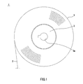
- FIG. 1 is a side view showing a reel member to which the present invention is applied.
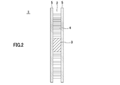
- FIG. 2 is a cross-sectional view showing a reel member to which the present invention is applied.
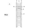
- FIG. 3 is a cross-sectional view showing a reel member in which a rib is provided on the reel flange 5.
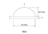
- FIG. 4 is a cross-sectional view showing one shape of the rib.
- FIG. 5 is a cross-sectional view showing one shape of the rib.
- FIG. 6 is a plan view showing one shape of the rib.
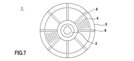
- FIG. 7 is a plan view showing one shape of the rib.
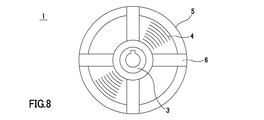
- FIG. 8 is a plan view showing one shape of the rib.
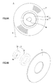
- FIG. 9A is a cross-sectional view showing a reel member formed by fitting a core having a large and small core
- FIG. 9B is an exploded perspective view
- FIG. 10 is a cross-sectional view showing a state where a gap is provided in a reel member in which a rib is provided on the reel flange.
- FIG. 11A is a perspective view showing a diameter-enlarged state of a winding core constituted by an air shaft
- FIG. 11B is a perspective view showing a state where the diameter is reduced.
- FIG. 12 is a cross-sectional view showing a state where a gap is provided in a reel member in which no rib is provided on the reel flange.
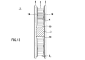
- FIG. 13 is a cross-sectional view showing a reel member in which a taper-shaped rib is provided on the reel flange.
- FIG. 14 is a cross-sectional view showing a state where the reel flange is inclined in a reel member in which a rib is provided on the reel flange.
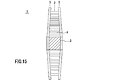
- FIG. 15 is a cross-sectional view illustrating a state where the reel flange is inclined in a reel member in which the rib is not provided on the reel flange.
- FIG. 16 is a front view showing a state in which the adhesive film is passed between the leave flanges while being tilted by the guide roller.
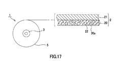
- FIG. 17 is a cross-sectional view showing the configuration of the adhesive film.
- FIG. 18 is a perspective view showing a conventional reel member.
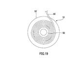
- FIG. 19 is a side view showing a state in which winding deviation or loosening occurs in a conventional reel member.
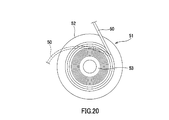
- FIG. 20 is a side view showing a state in which winding of the conventional
- a reel member 1 to which the present invention is applied includes a core 3 around which a tape-like adhesive film 2 is wound, and reel flanges 5 provided on both sides of the core 3.
- the adhesive film 2 wound around the reel member 1 forms a film winding body 4 wound around the core 3.
- the winding core 3 has a cylindrical shape and has substantially the same width as the adhesive film 2 described later. Further, the core 3 is formed with an insertion port 3a through which a rotating device (not shown) for rotating the reel member 1 is inserted at the center. The winding core 3 is engaged with a pair of reel flanges 5 on both sides and rotated integrally with the reel flange 5.
- the pair of reel flanges 5 sandwich the adhesive film 2 wound around the core 3, and are formed in a disk shape using a transparent plastic material, for example. Further, the reel flange 5 may be subjected to electrostatic treatment on the surface in contact with the adhesive film 2. Examples of the method for applying electrostatic treatment include a method of applying a compound such as polythiophene.
- the reel member 1 can prevent blocking of the adhesive film 2 from sticking out of the binder resin, or the sticking out binder resin to the reel flange 5 and preventing the adhesive film 2 from being normally unwound.
- the reel member 1 holds the film winding body 4 between the pair of reel flanges 5 so that the adhesive film 2 is forcibly pulled while the rotation of the core 3 and the reel flange 5 is restricted.
- pulling out of the adhesive film 2 can be suppressed, and the occurrence of winding tightening and the accumulation of winding pressure can be prevented. Therefore, according to the reel member 1, for example, when the adhesive film 2 is pulled around the roller of the transport device, even when the adhesive film 2 is pulled while the rotation of the reel member 1 is locked, the adhesive film 2 can be easily It is possible to prevent the binder resin from protruding and blocking due to winding tightening.
- the reel member 1 can hold the adhesive film 2 by the reel flange 5 by making the distance between the pair of reel flanges 5 the same as the width of the adhesive film 2.
- the reel member 1 has a plurality of ribs 6 formed radially from the inner peripheral side to the outer peripheral side on the inner surface facing the film winding body 4, and the film winding is performed by the ribs 6.
- the body 4 may be clamped.
- the distance between the ribs 6 provided opposite to the pair of reel flanges 5 is the same as the width of the adhesive film 2, whereby the adhesive film 2 is formed by the ribs 6 of the reel flange 5.
- the film winding body 4 can be held.
- the reel member 1 sandwiches the film winding body 4 by the rib 6, thereby reducing the contact area with the film winding body 4 compared to the case where the film winding body 4 is sandwiched across the entire surface of the reel flange 5. Thus, blocking due to contact with the binder resin protruding from the adhesive film 2 can be suppressed.
- the rib 6 may be formed in a substantially semicircular cross section as shown in FIG. 4, and the cross section may be formed in a substantially rectangular shape as shown in FIG. 5.
- the rib 6 can be formed with a size of, for example, a width of 0.5 mm to 5.0 mm and a height of 0.03 mm to 2.0 mm.
- the rib 6 may have a shape that curves from the inner peripheral side to the outer peripheral side of the reel flange 5. In this case, since the reel member 1 has a large contact area between the film winding body 4 and the rib 6, the number of ribs 6 can be reduced.
- the ribs 6 may be alternately provided between the pair of reel flanges 5 at predetermined intervals.
- the load on the film winding body 4 is small and the shape stability of the adhesive film 2 is excellent.
- the rib 6 may be formed in a wide rectangular plate shape as shown in FIG. In this case, since the film winding body 4 is widely supported by the ribs 6 by being in contact with the wide ribs 6, the number of the ribs 6 is reduced and the contact between the ribs 6 and the film winding body 4 is reduced. The area can be maintained.
- the rib 6 is formed from the inner periphery to the outer periphery of the reel flange 5, so that the winding pressure accumulated in the film winding body 4 and the internal stress generated in the reel flange 5 itself are changed due to a change with time. By manifesting, it is possible to prevent the reel flange 5 from being distorted. Therefore, it is possible to prevent the adhesive film 2 from falling off due to the gap between the pair of reel flanges 5 being opened.
- the tolerance of the gap error between the pair of reel flanges 5 is also low. Further, as the adhesive film 2 becomes longer, the diameter of the reel flange 5 becomes larger, and it is difficult to maintain a dimensional tolerance over the entire surface. Therefore, the reel flange 5 is formed with ribs 6 having a small dimensional tolerance from the inner periphery to the outer rim, thereby absorbing the dimensional tolerance of the reel flange 5 and separating the pair of reel flanges due to the distortion of the reel flange 5. It is possible to prevent the adhesive film 2 from dropping off from the film winding body 4 (see FIG. 20), and to make the adhesive film 2 longer and narrower.
- the reel member 1 has a pair of reel flanges 5 engaged with the core 3 so as to be close to and away from each other, so that the distance between the reel flanges 5 and the distance between the ribs 6 according to the width of the adhesive film 2.
- the distance can be adjusted.
- an engagement shaft that is inserted into an engagement port such as the insertion port 3 a provided in the core 3 is erected on the inner peripheral surface of the reel flange 5, and the reel flange 5 depends on the insertion depth of the engagement shaft.
- the structure which adjusts the distance between can be illustrated.
- the reel member 1 includes a winding core 3 that includes a small-diameter core 8 and a large-diameter core 9 that is fitted to the small-diameter core 8 and on which the adhesive film 2 is wound. Also good.
- the small-diameter core 8 is formed with an insertion port 8a through which a rotating device (not shown) that rotates the reel member 1 is inserted.
- the large diameter core 9 is detachably fitted from the small diameter core 8.
- the adhesive film 2 is wound around the large-diameter core 9 in a state where the diameter is expanded by fitting the small-diameter core 8 and the large-diameter core 9 together.
- the core 3 is reduced in diameter by removing the large diameter core 9 from the small diameter core 8 as shown in FIG. 9B.
- the reel member 1 is provided with a gap 10 between the film winding body 4 and the small-diameter core 8. This gap 10 is an area for absorbing the winding pressure accumulated on the inner peripheral side of the wound body when the film winding body 4 is tightened.
- the reel member 1 suppresses the accumulation of the winding pressure by releasing the winding pressure by the adhesive film 2 on the inner circumferential side of the wound body when the winding pressure is transmitted to the inner circumferential side. And the protrusion and blocking of the adhesive film 2 can be prevented.
- the reel member 1 is composed of an air shaft 11 having a variable outer diameter as shown in FIG. Also good.
- the adhesive film 2 is wound around the core 3 in a state in which the lug 12 protrudes and the diameter is increased. Then, when the winding of the adhesive film 2 is completed, the lug 12 is retracted into the shaft and the diameter of the core 3 is reduced, as shown in FIG. 11B. Also by this, as shown in FIG. 10, the reel member 1 is provided with a gap 10 between the film winding body 4 and the air shaft 11.
- the reel member 1 holds the film winding body 4 between the pair of reel flanges 5, after the winding of the adhesive film 2 is finished, the large-diameter core 9 is removed, or Even when the diameter of the core 3 is reduced by retracting the lug 12, the wound state can be maintained without the film winding body 4 being separated.
- the core 3 may be reduced in diameter to provide the gap 10.
- the reel member 1 may be strongly clamped from the inner peripheral side to the outer peripheral side of the film winding body 4 by a pair of reel flanges. Thereby, the reel member 1 prevents the winding pressure from accumulating from the outer peripheral side of the film winding body 4 to the inner peripheral side, and the winding on the inner peripheral side of the film winding body 4 that is likely to protrude or block. Tightening can be suppressed.
- the reel member 1 can be easily pulled out even when the adhesive film 2 is forcibly pulled while the rotation of the reel member 1 is locked and the rotation of the core 3 and the reel flange 5 is restricted. It is not possible to prevent the binder resin from protruding or blocking due to winding tightening.
- the reel member 1 is difficult to be clamped at a uniform pressure between the inner peripheral side and the outer peripheral side of the film wound body 4 by increasing the diameter of the reel flange 5 as the adhesive film 2 becomes longer.
- the shortage of the clamping pressure on the outer peripheral side can be eliminated by configuring the film winding body 4 to be strongly clamped from the inner peripheral side to the outer peripheral side.
- the reel flange 5 has a height from the inner peripheral side to the outer peripheral side, as shown in FIG. 13. It can be formed by providing a tapered rib 14 that increases.
- the gap 10 is provided between the winding core 3 and the film winding body 4 by reducing the diameter of the winding core 3.
- the angle ⁇ 1 of the tapered rib 14 is set, for example, in the range of 0.1 ° to 5 °, preferably 0.3 °.
- the reel member 1 may be configured such that the outer peripheral side of the pair of reel flanges 5 is narrowed by bending or bending the outer peripheral side of the reel flange 5.
- the reel flange 5 may form a rib 6, and the outer periphery side of the film winding body 4 may be strongly clamped by the rib 6, and the rib 6 is not provided as shown in FIG.
- the outer peripheral side of the film winding body 4 may be strongly held by the outer peripheral side inner surface.
- the inclination angle ⁇ 2 of the reel flange 5 is set in a range of 0.2 ° to 5 °, for example.
- the inclination angle ⁇ 3 of the guide roller 15 is set in the range of 0.1 ° to 15 °, for example.
- the adhesive film 2 that has passed between the pair of reel flanges 5 is wound in parallel with the outer peripheral surface of the core 3 to form a film wound body 4, and the inner peripheral surface of the pair of reel flanges 5 or the ribs 6, 14 will be held. Thereby, the adhesive film 2 can be smoothly wound around the reel member 1.
- the adhesive film 2 is passed between the pair of reel flanges 5 while being guided by the guide roller 15 so as to be inclined with respect to the outer periphery of the core 3. Thereby, the adhesive film 2 can be smoothly unwound from the reel member 1 without slidingly contacting the reel flange 5.
- the unwound adhesive film 2 forms the film winding body 4 and is sandwiched between the inner peripheral surfaces of the pair of reel flanges 5 or the ribs 6 and 14, and thus is applied at the time of unwinding. It is possible to prevent the load from being transmitted to the film winding body 4 as a winding pressure, and to prevent the binder resin from protruding or blocking due to winding tightening.
- the adhesive film 2 wound around the reel member 1 will be described.
- the adhesive film 2 includes an adhesive layer 20 and a base film 21 serving as a support that supports the adhesive layer 20.
- the adhesive layer 20 can be an anisotropic conductive film (ACF: Anisotropic Conductive Film) containing conductive particles 22 in a binder (insulating adhesive composition) 20a, but is not limited thereto.
- ACF Anisotropic Conductive Film
- NCF Non-Conductive Film
- the binder 20a of the adhesive film for example, a normal binder containing a film forming resin, a thermosetting resin, a latent curing agent, a silane coupling agent, or the like can be used.
- a normal binder containing a film forming resin, a thermosetting resin, a latent curing agent, a silane coupling agent, or the like can be used.
- an anisotropic conductive composition in which the conductive particles 22 are dispersed in the binder 20 a or an insulating adhesive composition that does not contain the conductive particles 22 in the binder 20 a is applied on the base film 21.
- the film is formed on the base film 21.
- the base film 21 supports the binder 20a in the form of a film.
- PET Poly Ethylene Terephthalate
- OPP Oriented Polypropylene
- PMP Poly-4-methlpentene-1
- PTFE Polytetrafluoroethylene
- the film-forming resin contained in the binder 20a is preferably a resin having an average molecular weight of about 10,000 to 80,000.
- the film forming resin include various resins such as an epoxy resin, a modified epoxy resin, a urethane resin, and a phenoxy resin. Among these, phenoxy resin is particularly preferable from the viewpoint of film formation state, connection reliability, and the like.
- thermosetting resin is not particularly limited as long as it has fluidity at room temperature, and examples thereof include commercially available epoxy resins and acrylic resins.
- the epoxy resin is not particularly limited.
- naphthalene type epoxy resin biphenyl type epoxy resin, phenol novolac type epoxy resin, bisphenol type epoxy resin, stilbene type epoxy resin, triphenolmethane type epoxy resin, phenol aralkyl type epoxy resin.
- an acrylic compound, liquid acrylate, etc. can be selected suitably.
- what made acrylate the methacrylate can also be selected from methyl acrylate, ethyl acrylate, isopropy
- the latent curing agent is not particularly limited, and examples thereof include various curing agents such as a heat curing type and a UV curing type.
- the latent curing agent does not normally react, but is activated by various triggers selected according to applications such as heat, light, and pressure, and starts the reaction.
- the activation method of the thermally activated latent curing agent includes a method of generating active species (cations and anions) by a dissociation reaction by heating, and the like.
- Thermally active latent curing agents include imidazole series, hydrazide series, boron trifluoride-amine complex, sulfonium salt, amine imide, polyamine salt, dicyandiamide, and modified products thereof. The above mixture may be sufficient. Among these, a microcapsule type imidazole-based latent curing agent is preferable.
- the silane coupling agent is not particularly limited, and examples thereof include an epoxy type, an amino type, a mercapto sulfide type, and a ureido type. By adding the silane coupling agent, the adhesion at the interface between the organic material and the inorganic material is improved.
- Examples of the conductive particles 22 include any known conductive particles used in anisotropic conductive films.
- Examples of the conductive particles 22 include particles of various metals and metal alloys such as nickel, iron, copper, aluminum, tin, lead, chromium, cobalt, silver, gold, metal oxide, carbon, graphite, glass, ceramic, Examples thereof include those in which the surface of particles such as plastic is coated with metal, or those in which the surface of these particles is further coated with an insulating thin film.
- examples of the resin particle include an epoxy resin, a phenol resin, an acrylic resin, an acrylonitrile / styrene (AS) resin, a benzoguanamine resin, a divinylbenzene resin, a styrene resin, and the like. Can be mentioned.
- the adhesive film 2 in which the adhesive film 2 made of ACF or NCF is laminated on the base film 21 is used.
- the present invention is not limited to this example.
- the film laminate may be an anisotropic conductive film having two or more layers in which ACF and NCF are laminated.
- the adhesive film 2 may have a configuration in which a cover film is provided on the surface opposite to the surface on which the base film 21 of the adhesive film 2 is laminated.
- a cover film is provided on the surface opposite to the surface on which the base film 21 of the adhesive film 2 is laminated.
- it is good also as an adhesive film with copper foil for electrically connecting the electrodes of a plurality of photovoltaic cells.
- a reel member that sandwiches the wound body of the adhesive film with a pair of reel flanges and a conventional reel member are prepared, the adhesive film is pulled out, and the length of the adhesive film is extended or blocked. The occurrence was observed.
- Example 1 a reel member in which 12 linear ribs are radially formed on the inner surface facing the film winding body from the inner peripheral side to the outer peripheral side, and the film winding body is sandwiched by the ribs. was used (see FIG. 3).
- the outer diameter of the reel flange is 250 mm.
- Example 2 the same conditions as in Example 1 were used except that a winding core composed of a large-diameter core and a small-diameter core was used and a reel member in which a gap was formed between the film winding body and the winding core was used. (See FIG. 10).
- Example 3 12 taper-shaped ribs were radially formed on the inner surface facing the film winding body from the inner peripheral side toward the outer peripheral side, and the film winding body was sandwiched by the tapered ribs.
- a reel member was used (see FIG. 13).
- the outer diameter of the reel flange is 300 mm.
- the taper angle of the tapered rib is 0.3 °.
- the core which consists of a large diameter core and a small diameter core was used, and the space
- Comparative Example 1 a conventional reel member having a clearance between the film winding body and the reel flange was used (see FIG. 18).
- the reel members according to Examples and Comparative Examples were each wound with an adhesive film of 300 m, 500 m, 600 m, and 700 m, and observed for protrusion and blocking. ⁇ when no protrusion or blocking is observed, and when protrusion is recognized but blocking is not recognized, it is ⁇ as no problem in practical use, and when protrusion and blocking are recognized, it is assumed that it cannot be put into practical use. It was. The results are shown in Table 1.
- Example 2 when looking at Examples 1 to 3, the protrusion in Example 2 with a gap was suppressed more than in Example 1 when the length was increased. From this, it can be seen that the formation of voids is advantageous for suppressing the cumulative winding pressure. Further, the protrusion of Example 3 in which the tapered rib was formed was suppressed from being extended when the length was increased. From this, it can be seen that it is advantageous for the accumulation suppression of the winding pressure that the film winding body is strongly held from the inner peripheral side to the outer peripheral side.
Landscapes
- Storage Of Web-Like Or Filamentary Materials (AREA)
Priority Applications (3)
| Application Number | Priority Date | Filing Date | Title |
|---|---|---|---|
| KR1020207014474A KR102268491B1 (ko) | 2012-04-06 | 2013-04-01 | 릴 부재, 접착 필름의 권회 방법, 접착 필름의 권출 방법 |
| KR1020147030861A KR102123310B1 (ko) | 2012-04-06 | 2013-04-01 | 릴 부재, 접착 필름의 권회 방법, 접착 필름의 권출 방법 |
| CN201380017718.5A CN104203789B (zh) | 2012-04-06 | 2013-04-01 | 卷盘部件、粘接膜的卷绕方法、粘接膜的卷出方法 |
Applications Claiming Priority (2)
| Application Number | Priority Date | Filing Date | Title |
|---|---|---|---|
| JP2012087758A JP5982159B2 (ja) | 2012-04-06 | 2012-04-06 | リール部材、接着フィルムの巻回方法、接着フィルムの巻き出し方法 |
| JP2012-087758 | 2012-04-06 |
Publications (1)
| Publication Number | Publication Date |
|---|---|
| WO2013151013A1 true WO2013151013A1 (ja) | 2013-10-10 |
Family
ID=49300496
Family Applications (1)
| Application Number | Title | Priority Date | Filing Date |
|---|---|---|---|
| PCT/JP2013/059949 Ceased WO2013151013A1 (ja) | 2012-04-06 | 2013-04-01 | リール部材、接着フィルムの巻回方法、接着フィルムの巻き出し方法 |
Country Status (5)
| Country | Link |
|---|---|
| JP (1) | JP5982159B2 (2) |
| KR (2) | KR102123310B1 (2) |
| CN (1) | CN104203789B (2) |
| TW (1) | TW201400394A (2) |
| WO (1) | WO2013151013A1 (2) |
Cited By (2)
| Publication number | Priority date | Publication date | Assignee | Title |
|---|---|---|---|---|
| EP4207965A1 (en) * | 2021-12-31 | 2023-07-05 | Nexperia B.V. | An electronic component packing reel |
| US20230339720A1 (en) * | 2019-11-22 | 2023-10-26 | Dexerials Corporation | Reel member and adhesive film winding body |
Families Citing this family (3)
| Publication number | Priority date | Publication date | Assignee | Title |
|---|---|---|---|---|
| KR102106253B1 (ko) | 2015-08-10 | 2020-05-04 | 데쿠세리아루즈 가부시키가이샤 | 릴 부재, 필름 수용체, 및 릴 부재의 제조 방법 |
| KR102108476B1 (ko) * | 2017-10-31 | 2020-05-07 | 김태민 | 크리스탈 칩을 이용한 프린팅 시스템에서 사용되는 크리스탈 칩용 릴 |
| CN118919876B (zh) * | 2024-10-08 | 2025-06-03 | 浙江晶科储能有限公司 | 储能电芯及其制备方法 |
Citations (9)
| Publication number | Priority date | Publication date | Assignee | Title |
|---|---|---|---|---|
| JPS5552672U (2) * | 1978-09-30 | 1980-04-08 | ||
| JPH10329992A (ja) * | 1997-05-29 | 1998-12-15 | Nec Toyama Ltd | キャリアテープリール |
| WO2007148593A1 (ja) * | 2006-06-21 | 2007-12-27 | Hitachi Chemical Company, Ltd. | リール |
| WO2008053824A1 (en) * | 2006-10-31 | 2008-05-08 | Hitachi Chemical Company, Ltd. | Adhesive tape and adhesive tape roll |
| JP2009113877A (ja) * | 2007-11-01 | 2009-05-28 | Kao Corp | ロール状巻回物の巻き出し方法及び巻芯 |
| JP2011026064A (ja) * | 2009-07-24 | 2011-02-10 | Hitachi Chem Co Ltd | リール |
| JP2011058007A (ja) * | 2010-12-24 | 2011-03-24 | Sony Chemical & Information Device Corp | リール体及びリール体の製造方法 |
| JP2011126711A (ja) * | 2009-11-18 | 2011-06-30 | Hitachi Chem Co Ltd | 異方導電フィルム用リール、異方導電フィルム巻、及び回路部材の接続方法 |
| WO2011118503A1 (ja) * | 2010-03-23 | 2011-09-29 | 日立化成工業株式会社 | 接着テープ用リール |
Family Cites Families (8)
| Publication number | Priority date | Publication date | Assignee | Title |
|---|---|---|---|---|
| JP2523990Y2 (ja) * | 1989-09-29 | 1997-01-29 | 金井 宏之 | 金属線条体巻装用リール |
| SE502768C2 (sv) * | 1994-03-29 | 1996-01-08 | Ulvator Ab | Metallfri engångstrumma för ett långsträckt böjligt föremål |
| AU2308497A (en) * | 1996-05-30 | 1998-01-05 | Kolon Industries, Inc. | Reel for winding photosensitive film |
| KR200221348Y1 (ko) * | 1997-06-11 | 2001-05-02 | 윤종용 | 광섬유 출하용 스풀 및 스풀 커버 |
| JP3680669B2 (ja) | 1999-12-17 | 2005-08-10 | ソニーケミカル株式会社 | 多層異方性導電膜積層体 |
| US7237746B2 (en) * | 2003-12-08 | 2007-07-03 | Sonoco Development, Inc. | Spool having reversing spiral guide |
| WO2007015372A1 (ja) | 2005-08-04 | 2007-02-08 | Hitachi Chemical Co., Ltd. | 異方導電フィルム及びその製造方法 |
| KR100961589B1 (ko) * | 2007-05-23 | 2010-06-04 | 히다치 가세고교 가부시끼가이샤 | 접착재 릴 및 이를 이용한 회로 접속체의 제조 방법 |
-
2012
- 2012-04-06 JP JP2012087758A patent/JP5982159B2/ja active Active
-
2013
- 2013-04-01 WO PCT/JP2013/059949 patent/WO2013151013A1/ja not_active Ceased
- 2013-04-01 KR KR1020147030861A patent/KR102123310B1/ko active Active
- 2013-04-01 KR KR1020207014474A patent/KR102268491B1/ko active Active
- 2013-04-01 CN CN201380017718.5A patent/CN104203789B/zh active Active
- 2013-04-08 TW TW102112452A patent/TW201400394A/zh unknown
Patent Citations (9)
| Publication number | Priority date | Publication date | Assignee | Title |
|---|---|---|---|---|
| JPS5552672U (2) * | 1978-09-30 | 1980-04-08 | ||
| JPH10329992A (ja) * | 1997-05-29 | 1998-12-15 | Nec Toyama Ltd | キャリアテープリール |
| WO2007148593A1 (ja) * | 2006-06-21 | 2007-12-27 | Hitachi Chemical Company, Ltd. | リール |
| WO2008053824A1 (en) * | 2006-10-31 | 2008-05-08 | Hitachi Chemical Company, Ltd. | Adhesive tape and adhesive tape roll |
| JP2009113877A (ja) * | 2007-11-01 | 2009-05-28 | Kao Corp | ロール状巻回物の巻き出し方法及び巻芯 |
| JP2011026064A (ja) * | 2009-07-24 | 2011-02-10 | Hitachi Chem Co Ltd | リール |
| JP2011126711A (ja) * | 2009-11-18 | 2011-06-30 | Hitachi Chem Co Ltd | 異方導電フィルム用リール、異方導電フィルム巻、及び回路部材の接続方法 |
| WO2011118503A1 (ja) * | 2010-03-23 | 2011-09-29 | 日立化成工業株式会社 | 接着テープ用リール |
| JP2011058007A (ja) * | 2010-12-24 | 2011-03-24 | Sony Chemical & Information Device Corp | リール体及びリール体の製造方法 |
Cited By (4)
| Publication number | Priority date | Publication date | Assignee | Title |
|---|---|---|---|---|
| US20230339720A1 (en) * | 2019-11-22 | 2023-10-26 | Dexerials Corporation | Reel member and adhesive film winding body |
| US12441580B2 (en) * | 2019-11-22 | 2025-10-14 | Dexerials Corporation | Reel member and adhesive film winding body |
| EP4207965A1 (en) * | 2021-12-31 | 2023-07-05 | Nexperia B.V. | An electronic component packing reel |
| US12297069B2 (en) | 2021-12-31 | 2025-05-13 | Nexperia B.V. | Electronic component packing reel |
Also Published As
| Publication number | Publication date |
|---|---|
| KR20200060526A (ko) | 2020-05-29 |
| JP5982159B2 (ja) | 2016-08-31 |
| CN104203789A (zh) | 2014-12-10 |
| KR102123310B1 (ko) | 2020-06-16 |
| JP2013216436A (ja) | 2013-10-24 |
| TWI562949B (2) | 2016-12-21 |
| KR20140143220A (ko) | 2014-12-15 |
| CN104203789B (zh) | 2016-10-05 |
| TW201400394A (zh) | 2014-01-01 |
| KR102268491B1 (ko) | 2021-06-24 |
Similar Documents
| Publication | Publication Date | Title |
|---|---|---|
| KR101909300B1 (ko) | 릴체 및 릴체의 제조 방법 | |
| JP5982159B2 (ja) | リール部材、接着フィルムの巻回方法、接着フィルムの巻き出し方法 | |
| KR102213418B1 (ko) | 접착 필름 권장체, 접착 필름 권장체의 제조 방법 | |
| JP5996241B2 (ja) | 接着フィルムの貼着装置、接着フィルムの貼着方法、及び接続構造体 | |
| JP6297381B2 (ja) | 接着フィルム、フィルム巻装体、接続体の製造方法 | |
| JP5982158B2 (ja) | リール部材 | |
| TWI494956B (zh) | An anisotropic conductive film, an anisotropic conductive film manufacturing method, a connection method between electronic members, and a connection structure | |
| JP5981173B2 (ja) | 接続体の製造方法、接着フィルムの貼り合わせ方法、接着フィルムの引き出し方法及び接着フィルム | |
| KR101808347B1 (ko) | 필름 적층체, 필름 적층체의 부착 방법, 필름 적층체를 이용한 접속 방법 및 접속 구조체 | |
| JP6431256B2 (ja) | 接着フィルム、フィルム巻装体、接続構造体の製造方法、接続方法、接続構造体 | |
| JP5897942B2 (ja) | リール部材、フィルム巻回方法、フィルム巻き出し方法 | |
| JP5912700B2 (ja) | リール部材、接着フィルムの巻回方法及び巻き出し方法 | |
| JP2018135517A (ja) | 接着フィルム、フィルム巻装体、接続体の製造方法 | |
| JP6366975B2 (ja) | 接着フィルム巻装体、接続体の製造方法及び電子部品の接続方法 | |
| JP2013201351A (ja) | 接続体の製造方法、接続部材の接続方法及び接続体 | |
| WO2013146479A1 (ja) | 接続体の製造方法、電子部品の接続方法、接続部材、接続部材の製造方法 | |
| JP2015024900A (ja) | リール部材、接着フィルムの引き出し方法、接続方法 | |
| HK1177332B (en) | Anisotropic conductive film and method of production the same, connection method between electronic components, and connection structure |
Legal Events
| Date | Code | Title | Description |
|---|---|---|---|
| 121 | Ep: the epo has been informed by wipo that ep was designated in this application |
Ref document number: 13773114 Country of ref document: EP Kind code of ref document: A1 |
|
| NENP | Non-entry into the national phase |
Ref country code: DE |
|
| ENP | Entry into the national phase |
Ref document number: 20147030861 Country of ref document: KR Kind code of ref document: A |
|
| 122 | Ep: pct application non-entry in european phase |
Ref document number: 13773114 Country of ref document: EP Kind code of ref document: A1 |