WO2013151144A1 - 二次電池用セパレータ - Google Patents
二次電池用セパレータ Download PDFInfo
- Publication number
- WO2013151144A1 WO2013151144A1 PCT/JP2013/060384 JP2013060384W WO2013151144A1 WO 2013151144 A1 WO2013151144 A1 WO 2013151144A1 JP 2013060384 W JP2013060384 W JP 2013060384W WO 2013151144 A1 WO2013151144 A1 WO 2013151144A1
- Authority
- WO
- WIPO (PCT)
- Prior art keywords
- separator
- secondary battery
- heat
- layer
- resistant layer
- Prior art date
- Legal status (The legal status is an assumption and is not a legal conclusion. Google has not performed a legal analysis and makes no representation as to the accuracy of the status listed.)
- Ceased
Links
Classifications
-
- H—ELECTRICITY
- H01—ELECTRIC ELEMENTS
- H01M—PROCESSES OR MEANS, e.g. BATTERIES, FOR THE DIRECT CONVERSION OF CHEMICAL ENERGY INTO ELECTRICAL ENERGY
- H01M10/00—Secondary cells; Manufacture thereof
- H01M10/05—Accumulators with non-aqueous electrolyte
- H01M10/052—Li-accumulators
- H01M10/0525—Rocking-chair batteries, i.e. batteries with lithium insertion or intercalation in both electrodes; Lithium-ion batteries
-
- H—ELECTRICITY
- H01—ELECTRIC ELEMENTS
- H01M—PROCESSES OR MEANS, e.g. BATTERIES, FOR THE DIRECT CONVERSION OF CHEMICAL ENERGY INTO ELECTRICAL ENERGY
- H01M50/00—Constructional details or processes of manufacture of the non-active parts of electrochemical cells other than fuel cells, e.g. hybrid cells
- H01M50/40—Separators; Membranes; Diaphragms; Spacing elements inside cells
- H01M50/409—Separators, membranes or diaphragms characterised by the material
- H01M50/449—Separators, membranes or diaphragms characterised by the material having a layered structure
-
- C—CHEMISTRY; METALLURGY
- C09—DYES; PAINTS; POLISHES; NATURAL RESINS; ADHESIVES; COMPOSITIONS NOT OTHERWISE PROVIDED FOR; APPLICATIONS OF MATERIALS NOT OTHERWISE PROVIDED FOR
- C09D—COATING COMPOSITIONS, e.g. PAINTS, VARNISHES OR LACQUERS; FILLING PASTES; CHEMICAL PAINT OR INK REMOVERS; INKS; CORRECTING FLUIDS; WOODSTAINS; PASTES OR SOLIDS FOR COLOURING OR PRINTING; USE OF MATERIALS THEREFOR
- C09D5/00—Coating compositions, e.g. paints, varnishes or lacquers, characterised by their physical nature or the effects produced; Filling pastes
- C09D5/02—Emulsion paints including aerosols
- C09D5/024—Emulsion paints including aerosols characterised by the additives
- C09D5/028—Pigments; Filters
-
- C—CHEMISTRY; METALLURGY
- C09—DYES; PAINTS; POLISHES; NATURAL RESINS; ADHESIVES; COMPOSITIONS NOT OTHERWISE PROVIDED FOR; APPLICATIONS OF MATERIALS NOT OTHERWISE PROVIDED FOR
- C09D—COATING COMPOSITIONS, e.g. PAINTS, VARNISHES OR LACQUERS; FILLING PASTES; CHEMICAL PAINT OR INK REMOVERS; INKS; CORRECTING FLUIDS; WOODSTAINS; PASTES OR SOLIDS FOR COLOURING OR PRINTING; USE OF MATERIALS THEREFOR
- C09D7/00—Features of coating compositions, not provided for in group C09D5/00; Processes for incorporating ingredients in coating compositions
- C09D7/40—Additives
- C09D7/60—Additives non-macromolecular
- C09D7/61—Additives non-macromolecular inorganic
-
- H—ELECTRICITY
- H01—ELECTRIC ELEMENTS
- H01M—PROCESSES OR MEANS, e.g. BATTERIES, FOR THE DIRECT CONVERSION OF CHEMICAL ENERGY INTO ELECTRICAL ENERGY
- H01M10/00—Secondary cells; Manufacture thereof
- H01M10/05—Accumulators with non-aqueous electrolyte
- H01M10/056—Accumulators with non-aqueous electrolyte characterised by the materials used as electrolytes, e.g. mixed inorganic/organic electrolytes
-
- H—ELECTRICITY
- H01—ELECTRIC ELEMENTS
- H01M—PROCESSES OR MEANS, e.g. BATTERIES, FOR THE DIRECT CONVERSION OF CHEMICAL ENERGY INTO ELECTRICAL ENERGY
- H01M50/00—Constructional details or processes of manufacture of the non-active parts of electrochemical cells other than fuel cells, e.g. hybrid cells
- H01M50/40—Separators; Membranes; Diaphragms; Spacing elements inside cells
- H01M50/403—Manufacturing processes of separators, membranes or diaphragms
-
- H—ELECTRICITY
- H01—ELECTRIC ELEMENTS
- H01M—PROCESSES OR MEANS, e.g. BATTERIES, FOR THE DIRECT CONVERSION OF CHEMICAL ENERGY INTO ELECTRICAL ENERGY
- H01M50/00—Constructional details or processes of manufacture of the non-active parts of electrochemical cells other than fuel cells, e.g. hybrid cells
- H01M50/40—Separators; Membranes; Diaphragms; Spacing elements inside cells
- H01M50/409—Separators, membranes or diaphragms characterised by the material
- H01M50/411—Organic material
- H01M50/414—Synthetic resins, e.g. thermoplastics or thermosetting resins
- H01M50/42—Acrylic resins
-
- H—ELECTRICITY
- H01—ELECTRIC ELEMENTS
- H01M—PROCESSES OR MEANS, e.g. BATTERIES, FOR THE DIRECT CONVERSION OF CHEMICAL ENERGY INTO ELECTRICAL ENERGY
- H01M50/00—Constructional details or processes of manufacture of the non-active parts of electrochemical cells other than fuel cells, e.g. hybrid cells
- H01M50/40—Separators; Membranes; Diaphragms; Spacing elements inside cells
- H01M50/409—Separators, membranes or diaphragms characterised by the material
- H01M50/443—Particulate material
-
- H—ELECTRICITY
- H01—ELECTRIC ELEMENTS
- H01M—PROCESSES OR MEANS, e.g. BATTERIES, FOR THE DIRECT CONVERSION OF CHEMICAL ENERGY INTO ELECTRICAL ENERGY
- H01M50/00—Constructional details or processes of manufacture of the non-active parts of electrochemical cells other than fuel cells, e.g. hybrid cells
- H01M50/40—Separators; Membranes; Diaphragms; Spacing elements inside cells
- H01M50/409—Separators, membranes or diaphragms characterised by the material
- H01M50/449—Separators, membranes or diaphragms characterised by the material having a layered structure
- H01M50/457—Separators, membranes or diaphragms characterised by the material having a layered structure comprising three or more layers
-
- H—ELECTRICITY
- H01—ELECTRIC ELEMENTS
- H01M—PROCESSES OR MEANS, e.g. BATTERIES, FOR THE DIRECT CONVERSION OF CHEMICAL ENERGY INTO ELECTRICAL ENERGY
- H01M50/00—Constructional details or processes of manufacture of the non-active parts of electrochemical cells other than fuel cells, e.g. hybrid cells
- H01M50/40—Separators; Membranes; Diaphragms; Spacing elements inside cells
- H01M50/46—Separators, membranes or diaphragms characterised by their combination with electrodes
- H01M50/461—Separators, membranes or diaphragms characterised by their combination with electrodes with adhesive layers between electrodes and separators
-
- H—ELECTRICITY
- H01—ELECTRIC ELEMENTS
- H01M—PROCESSES OR MEANS, e.g. BATTERIES, FOR THE DIRECT CONVERSION OF CHEMICAL ENERGY INTO ELECTRICAL ENERGY
- H01M50/00—Constructional details or processes of manufacture of the non-active parts of electrochemical cells other than fuel cells, e.g. hybrid cells
- H01M50/40—Separators; Membranes; Diaphragms; Spacing elements inside cells
- H01M50/463—Separators, membranes or diaphragms characterised by their shape
-
- C—CHEMISTRY; METALLURGY
- C08—ORGANIC MACROMOLECULAR COMPOUNDS; THEIR PREPARATION OR CHEMICAL WORKING-UP; COMPOSITIONS BASED THEREON
- C08K—Use of inorganic or non-macromolecular organic substances as compounding ingredients
- C08K3/00—Use of inorganic substances as compounding ingredients
- C08K3/18—Oxygen-containing compounds, e.g. metal carbonyls
- C08K3/20—Oxides; Hydroxides
- C08K3/22—Oxides; Hydroxides of metals
- C08K2003/2217—Oxides; Hydroxides of metals of magnesium
-
- C—CHEMISTRY; METALLURGY
- C08—ORGANIC MACROMOLECULAR COMPOUNDS; THEIR PREPARATION OR CHEMICAL WORKING-UP; COMPOSITIONS BASED THEREON
- C08K—Use of inorganic or non-macromolecular organic substances as compounding ingredients
- C08K3/00—Use of inorganic substances as compounding ingredients
- C08K3/18—Oxygen-containing compounds, e.g. metal carbonyls
- C08K3/20—Oxides; Hydroxides
- C08K3/22—Oxides; Hydroxides of metals
- C08K2003/2227—Oxides; Hydroxides of metals of aluminium
-
- C—CHEMISTRY; METALLURGY
- C08—ORGANIC MACROMOLECULAR COMPOUNDS; THEIR PREPARATION OR CHEMICAL WORKING-UP; COMPOSITIONS BASED THEREON
- C08K—Use of inorganic or non-macromolecular organic substances as compounding ingredients
- C08K3/00—Use of inorganic substances as compounding ingredients
- C08K3/18—Oxygen-containing compounds, e.g. metal carbonyls
- C08K3/20—Oxides; Hydroxides
- C08K3/22—Oxides; Hydroxides of metals
-
- H—ELECTRICITY
- H01—ELECTRIC ELEMENTS
- H01M—PROCESSES OR MEANS, e.g. BATTERIES, FOR THE DIRECT CONVERSION OF CHEMICAL ENERGY INTO ELECTRICAL ENERGY
- H01M10/00—Secondary cells; Manufacture thereof
- H01M10/05—Accumulators with non-aqueous electrolyte
- H01M10/052—Li-accumulators
-
- H—ELECTRICITY
- H01—ELECTRIC ELEMENTS
- H01M—PROCESSES OR MEANS, e.g. BATTERIES, FOR THE DIRECT CONVERSION OF CHEMICAL ENERGY INTO ELECTRICAL ENERGY
- H01M10/00—Secondary cells; Manufacture thereof
- H01M10/05—Accumulators with non-aqueous electrolyte
- H01M10/056—Accumulators with non-aqueous electrolyte characterised by the materials used as electrolytes, e.g. mixed inorganic/organic electrolytes
- H01M10/0564—Accumulators with non-aqueous electrolyte characterised by the materials used as electrolytes, e.g. mixed inorganic/organic electrolytes the electrolyte being constituted of organic materials only
- H01M10/0566—Liquid materials
-
- H—ELECTRICITY
- H01—ELECTRIC ELEMENTS
- H01M—PROCESSES OR MEANS, e.g. BATTERIES, FOR THE DIRECT CONVERSION OF CHEMICAL ENERGY INTO ELECTRICAL ENERGY
- H01M2220/00—Batteries for particular applications
- H01M2220/30—Batteries in portable systems, e.g. mobile phone, laptop
-
- H—ELECTRICITY
- H01—ELECTRIC ELEMENTS
- H01M—PROCESSES OR MEANS, e.g. BATTERIES, FOR THE DIRECT CONVERSION OF CHEMICAL ENERGY INTO ELECTRICAL ENERGY
- H01M50/00—Constructional details or processes of manufacture of the non-active parts of electrochemical cells other than fuel cells, e.g. hybrid cells
- H01M50/40—Separators; Membranes; Diaphragms; Spacing elements inside cells
- H01M50/489—Separators, membranes, diaphragms or spacing elements inside the cells, characterised by their physical properties, e.g. swelling degree, hydrophilicity or shut down properties
-
- Y—GENERAL TAGGING OF NEW TECHNOLOGICAL DEVELOPMENTS; GENERAL TAGGING OF CROSS-SECTIONAL TECHNOLOGIES SPANNING OVER SEVERAL SECTIONS OF THE IPC; TECHNICAL SUBJECTS COVERED BY FORMER USPC CROSS-REFERENCE ART COLLECTIONS [XRACs] AND DIGESTS
- Y02—TECHNOLOGIES OR APPLICATIONS FOR MITIGATION OR ADAPTATION AGAINST CLIMATE CHANGE
- Y02E—REDUCTION OF GREENHOUSE GAS [GHG] EMISSIONS, RELATED TO ENERGY GENERATION, TRANSMISSION OR DISTRIBUTION
- Y02E60/00—Enabling technologies; Technologies with a potential or indirect contribution to GHG emissions mitigation
- Y02E60/10—Energy storage using batteries
Definitions
- the present invention relates to a secondary battery separator used for a lithium ion secondary battery or the like.
- portable terminals such as notebook personal computers, mobile phones, and PDAs (Personal Digital Assistants) have become widespread.
- a lithium ion secondary battery or the like is frequently used.
- Mobile terminals are required to have more comfortable portability, and are rapidly becoming smaller, thinner, lighter, and higher performance.
- mobile terminals are used in various places.
- the battery is required to be smaller, thinner, lighter, and higher in performance as in the case of the portable terminal.
- lithium is dissolved from the positive electrode active material of the positive electrode into the electrolyte solution in the organic separator as lithium ions during charging, enters the negative electrode active material of the negative electrode, and the negative electrode of the negative electrode is discharged.
- the lithium ions that have entered the active material are released into the electrolytic solution, and are returned to the positive electrode active material of the positive electrode to perform the charge / discharge operation.
- an organic separator used for a lithium ion secondary battery for example, a microporous film made of polyolefin resin is used.
- the organic separator melts and closes the micropore when the temperature inside the battery reaches around 130 ° C, thereby preventing the movement of lithium ions and shutting down the current. Has a role to hold.
- the battery temperature exceeds, for example, 150 ° C. due to instantaneous heat generation, the organic separator contracts rapidly, and the positive electrode and the negative electrode may be in direct contact with each other to enlarge the location where the short circuit occurs. In this case, the battery temperature may reach a state where it is abnormally overheated to several hundred degrees Celsius or higher.
- heat-resistant layer a heat-resistant porous film layer
- organic separator such as a polyethylene microporous film
- the porous membrane layer is a membrane having a large number of linked micropore structures inside, and binds non-conductive particles, non-conductive particles, and non-conductive particles to an organic separator or a current collector. Therefore, it contains a polymer binder (hereinafter sometimes referred to as “binder”). Further, the porous membrane layer can be used by being laminated on an electrode, or can be used as an organic separator itself.
- Patent Document 1 discloses a non-aqueous secondary battery separator provided with a polyolefin microporous membrane and a heat-resistant porous layer containing a heat-resistant resin provided on one or both surfaces of the polyolefin microporous membrane, and a polyolefin microporous membrane.
- a separator for a non-aqueous secondary battery that includes a membrane and an adhesive porous layer that is provided on one or both surfaces of the polyolefin microporous membrane and contains a vinylidene fluoride resin has been proposed.
- Patent Document 1 it is described that a polyolefin microporous film is held even at a temperature equal to or higher than a shutdown temperature by a heat-resistant porous layer, melt-down hardly occurs, and safety at a high temperature can be ensured.
- the adhesive porous layer improves the adhesion with the separator for non-aqueous secondary batteries, and in addition to the mechanical strength, shutdown characteristics and liquid drainage effect of the polyolefin microporous membrane, the adhesive porous layer is excellent. It describes that it exhibits ion permeability and electrolyte retention.
- a lithium ion secondary battery is usually a laminate of a positive electrode having a current collector and a positive electrode active material layer and a negative electrode having a current collector and a negative electrode active material layer with a secondary battery separator interposed therebetween, and the laminate.
- the electrode body is formed by winding the electrode body.
- the electrode body is accommodated in the battery case, the electrolytic solution is injected into the battery case, and the opening is sealed.
- the separator having a polyolefin microporous membrane and a porous layer described in Patent Document 1 is used, non-conductive particles in the porous layer and the electrode active material in the electrode active material layer are easily detached. Therefore, in order to prevent this, it is preferable to perform hot pressing when laminating the positive electrode and the negative electrode through a secondary battery separator.
- the present invention has been made in view of the prior art as described above, has good heat resistance, high adhesion to the electrode active material layer laminated on the current collector, and excellent blocking resistance. It aims at providing the separator for secondary batteries. Furthermore, an object of this invention is to provide the secondary battery which has this separator for secondary batteries.
- the present inventors have made extensive studies and as a result, formed a heat-resistant layer and an adhesive layer on an organic separator layer, and further a specific weight as a polymer constituting the adhesive layer.
- a secondary battery separator having sufficient heat resistance and having excellent adhesion to the electrode active material layer laminated on the current collector and excellent blocking resistance can be obtained.
- the present invention has been completed. That is, this invention provides the following separator for secondary batteries, its manufacturing method, a use, etc.
- the present invention provides the following.
- a secondary battery separator having an organic separator layer, a heat-resistant layer formed adjacent to at least one surface of the organic separator layer, and an adhesive layer formed on the heat-resistant layer,
- the layer contains non-conductive particles and a binder, and the adhesive layer contains a particulate polymer having a glass transition temperature of 10 to 100 ° C.
- the particulate polymer contains an ethylenically unsaturated carboxylic acid monomer unit, and the content ratio of the ethylenically unsaturated carboxylic acid monomer unit in the particulate polymer is 1 to 50% by weight.
- the secondary battery separator according to any one of (1) to (4) above.
- a step of forming a heat-resistant layer by applying a slurry for heat-resistant layer containing non-conductive particles and a binder on the organic separator layer and drying, and a glass transition temperature (Tg) on the heat-resistant layer. Applying the slurry for the adhesive layer containing the particulate polymer having a temperature of 10 to 100 ° C. and forming the adhesive layer by drying, and (1) to (5) The manufacturing method of the separator for secondary batteries as described in 2 ..
- a secondary battery comprising a positive electrode, a negative electrode, a separator and an electrolytic solution, wherein the separator is the separator for a secondary battery according to any one of (1) to (5) above.
- the secondary battery separator of the present invention is excellent in all of heat resistance, adhesiveness, and blocking resistance by including a heat resistant layer and an adhesive layer. Therefore, the secondary battery having the secondary battery separator of the present invention is excellent in high-temperature cycle characteristics and rate characteristics.
- the separator for a secondary battery of the present invention is suitable for a cylindrical lithium ion secondary battery. Furthermore, according to the manufacturing method of the separator for secondary batteries of this invention, the separator for secondary batteries of this invention can be manufactured efficiently.
- the separator for a secondary battery of the present invention is for a secondary battery having an organic separator layer, a heat resistant layer formed adjacent to at least one surface of the organic separator layer, and an adhesive layer formed on the heat resistant layer.
- the heat-resistant layer contains non-conductive particles and a binder
- the adhesive layer contains a particulate polymer having a glass transition temperature (Tg) of 10 to 100 ° C.
- a porous film having a fine pore diameter which has no electron conductivity and ion conductivity and high resistance to an organic solvent.
- a polyolefin film polyethylene, polypropylene, polybutene, polyvinyl chloride
- a microporous film made of a resin such as a mixture or copolymer thereof, polyethylene terephthalate, polycycloolefin, polyether sulfone, polyamide, polyimide, polyimide amide
- a microporous membrane made of a resin such as polyaramid, polycycloolefin, nylon, and polytetrafluoroethylene, or a woven fabric of polyolefin fibers, a nonwoven fabric thereof, an aggregate of insulating substance particles, or the like.
- the thickness of the secondary battery separator can be reduced, and the capacity per volume can be increased by increasing the ratio of the electrode active material layer in the battery.
- a microporous membrane made of polyolefin resin is preferred.
- the thickness of the organic separator layer is preferably 0.5 to 40 ⁇ m, more preferably 1 to 30 ⁇ m, and particularly preferably 1 to 10 ⁇ m.
- the organic separator layer used in the present invention may contain fillers and fiber compounds other than non-conductive particles for the purpose of controlling strength, hardness, and heat shrinkage rate.
- a low molecular compound or polymer is previously used for the purpose of improving adhesion or improving the liquid impregnation property by lowering the surface tension with the electrolytic solution.
- the surface of the organic separator layer may be coated with a compound, or may be subjected to electromagnetic radiation treatment such as ultraviolet rays or plasma treatment such as corona discharge / plasma gas.
- those coated with a polymer compound containing a polar group such as a carboxylic acid group, a hydroxyl group, and a sulfonic acid group are preferable from the viewpoint of high impregnation of the electrolytic solution and easy adhesion to the heat-resistant layer.
- the organic separator layer used in the present invention may have a multilayer structure having two or more layers that can be used as the organic separator layer for the purpose of increasing tear strength and piercing strength.
- Specific examples include a laminate of a polyethylene microporous membrane and a polypropylene microporous membrane, and a laminate of a nonwoven fabric and a polyolefin separator.
- the heat-resistant layer in the present invention contains non-conductive particles and a binder.
- the heat-resistant layer has a structure in which non-conductive particles are bound via a binder and voids between the non-conductive particles are formed. This void is a hole in the heat-resistant layer.
- Non-conductive particles As a material constituting the non-conductive particles, it is desired that the material is stably present in an environment where the lithium ion secondary battery is used and is electrochemically stable.
- various non-conductive inorganic particles and organic particles can be used.
- the inorganic particles include aluminum oxide (alumina), aluminum oxide hydrate (boehmite (AlOOH), gibbsite (Al (OH) 3 ), bakelite, magnesium oxide, magnesium hydroxide, iron oxide, Silicon oxide, titanium oxide (titania), oxides such as calcium oxide, nitrides such as aluminum nitride and silicon nitride, silica, barium sulfate, barium fluoride, calcium fluoride, etc.
- electrolyte Oxides are preferred from the standpoint of stability and potential stability at high temperatures, and titanium oxide, alumina, boehmite, magnesium oxide and magnesium hydroxide are particularly preferred from the standpoint of low water absorption and excellent heat resistance (eg, resistance to high temperatures of 180 ° C. or higher).
- titanium oxide, alumina, boehmite, magnesium oxide and Magnesium oxide is particularly preferred.
- polymer particles are usually used as the organic particles.
- the organic particles can control the affinity for water by adjusting the type and amount of functional groups on the surface, and thus can control the amount of water contained in the heat-resistant layer of the present invention.
- Preferred examples of the organic material for the non-conductive particles include various polymer compounds such as polystyrene, polyethylene, polyimide, melamine resin, and phenol resin.
- the polymer compound forming the particles can be used as a mixture, a modified product, a derivative, a random copolymer, an alternating copolymer, a graft copolymer, a block copolymer, a crosslinked product, and the like.
- the organic particles may be formed of a mixture of two or more polymer compounds.
- organic particles When organic particles are used as non-conductive particles, they may or may not have a glass transition temperature, but when the polymer compound forming the organic particles has a glass transition temperature, the glass transition temperature
- the temperature is usually 150 ° C. or higher, preferably 200 ° C. or higher, more preferably 250 ° C. or higher.
- the non-conductive particles may be subjected to element substitution, surface treatment, solid solution, or the like, if necessary. Further, the non-conductive particles may include one kind of the above materials alone in one particle, or may contain two or more kinds in combination at an arbitrary ratio. . Further, the non-conductive particles may be used in combination of two or more kinds of particles formed of different materials.
- the average particle size (volume average D50 average particle size) of the non-conductive particles is preferably 5 nm to 10 ⁇ m, and more preferably 10 nm to 5 ⁇ m.
- the average particle diameter of the non-conductive particles is in the range of 50 nm to 2 ⁇ m, it is more preferable because it is excellent in dispersion, ease of coating, and control of voids.
- the average particle diameter of the non-conductive particles in the present invention is the number average particle calculated by measuring the diameter of 100 non-conductive particle images randomly selected in a transmission electron micrograph and calculating the arithmetic average value thereof. Is the diameter.
- the BET specific surface area of these non-conductive particles is specifically 0.9 to 200 m 2 / g from the viewpoint of suppressing particle aggregation and optimizing the fluidity of the heat-resistant layer slurry. It is preferably 1.5 to 150 m 2 / g.
- the BET specific surface area of the non-conductive particles is measured by a BET measurement method by using a specific surface area measuring device (Gemini 2310: manufactured by Shimadzu Corporation) to adsorb nitrogen gas to the daily conductive particles.
- the shape of the non-conductive particles is not particularly limited, and is not particularly limited, and may be a spherical shape, a needle shape, a rod shape, a scale shape, a plate shape, a tetrapod (registered trademark) shape (connected particles), etc.
- a tetrapod shape (connected particles), a plate shape, and a scale shape are preferable.
- the inorganic particles have the above-described shape, the porosity (porosity) of the heat-resistant layer is ensured, and a decrease in ionic conductivity can be suppressed.
- the content ratio of non-conductive particles in the heat-resistant layer is preferably 70 to 97% by weight, and more preferably 80 to 95% by weight.
- the heat-resistant layer in the present invention contains a binder.
- the binder plays a role of maintaining the mechanical strength of the heat-resistant layer.
- various binders can be used as long as they have binding properties.
- a polymer containing a conjugated diene polymer, an acrylate monomer unit and / or a methacrylic acid ester monomer unit hereinafter, referred to as “(meth) acrylic polymer”.
- (meth) acrylic polymer a polymer containing a conjugated diene polymer, an acrylate monomer unit and / or a methacrylic acid ester monomer unit
- (meth) acrylic polymer hereinafter, referred to as “(meth) acrylic polymer”.
- Acryl means acrylic and / or methacrylic), fluoropolymers, silicon polymers and the like.
- a conjugated diene polymer and a (meth) acrylic polymer from the viewpoint that it is easy to obtain a battery having excellent non-conductive particle retention and flexibility in the obtained heat-resistant layer, and being stable in redox and having excellent life characteristics.
- (meth) acrylic polymers are particularly preferred.
- the conjugated diene polymer is a polymer containing a conjugated diene monomer unit and a hydride thereof.
- the conjugated diene monomer unit is a repeating unit obtained by polymerizing a conjugated diene monomer.
- Examples of the conjugated diene monomer constituting the conjugated diene monomer unit include 1,3-butadiene, isoprene, chloroprene and the like.
- the conjugated diene polymer can contain a monomer unit of a monomer copolymerizable with the conjugated diene as an optional component.
- Examples of the monomer constituting the monomer unit copolymerizable with the conjugated diene include non-conjugated diene monomers such as 1,2-butadiene; ⁇ -olefins such as ethylene, propylene, and isobutylene; Aromatic vinyl monomers; vinyl cyanide monomers such as acrylonitrile and methacrylonitrile; These copolymerizable monomers can be used alone or in combination of two or more.
- conjugated diene polymer examples include conjugated diene homopolymers such as polybutadiene and polyisoprene; styrene / butadiene copolymer (SBR), styrene / butadiene / styrene block copolymer (SBS), styrene / isoprene / styrene.
- conjugated diene homopolymers such as polybutadiene and polyisoprene
- SBR styrene / butadiene copolymer
- SBS styrene / butadiene / styrene block copolymer
- isoprene / styrene examples include conjugated diene homopolymers such as polybutadiene and polyisoprene; styrene / butadiene copolymer (SBR), styrene / butadiene /
- Aromatic vinyl / conjugated diene copolymer such as block copolymer (SIS) and its hydride; aromatic vinyl / conjugated such as styrene / butadiene / methacrylic acid copolymer and styrene / butadiene / itaconic acid copolymer And copolymers of diene / carboxylic acid group-containing monomers; vinyl cyanide / conjugated diene copolymers such as acrylonitrile / butadiene copolymer (NBR) and hydrides thereof; and the like.
- SIS block copolymer
- NBR acrylonitrile / butadiene copolymer
- the acrylic ester monomer unit is a repeating unit obtained by polymerizing an acrylic ester monomer
- the methacrylic ester monomer unit is a repeating unit obtained by polymerizing a methacrylate monomer.
- Examples of acrylic acid ester and / or methacrylic acid ester include methyl acrylate, ethyl acrylate, n-propyl acrylate, isopropyl acrylate, n-butyl acrylate, t-butyl acrylate, pentyl acrylate, hexyl acrylate, heptyl acrylate, octyl acrylate, 2- Acrylic acid alkyl esters such as ethylhexyl acrylate, nonyl acrylate, decyl acrylate, lauryl acrylate, n-tetradecyl acrylate, stearyl acrylate; methyl methacrylate, ethyl methacrylate, n-propy
- acrylic acid alkyl ester is preferable, at least one selected from the group consisting of ethyl acrylate, butyl acrylate, and 2-ethylhexyl acrylate is preferable, and butyl acrylate is more preferable.
- the content ratio of the monomer units of the (meth) acrylic acid ester in the (meth) acrylic polymer is preferably 50 to 98% by weight, more preferably 60 to 97.5% by weight, and 70 to It is particularly preferably 95% by weight.
- the (meth) acrylic polymer preferably contains a (meth) acrylonitrile monomer unit in addition to the (meth) acrylic acid ester monomer unit.
- a battery having a long life and stable in redox can be obtained.
- a (meth) acrylic polymer containing these repeating units as a binder, the flexibility of the heat-resistant layer is improved, so that non-conductive particles are removed from the heat-resistant layer during cutting (slit) processing or winding. Desorption can be suppressed.
- (Meth) acrylonitrile monomer unit is a repeating unit obtained by polymerizing (meth) acrylonitrile.
- the binder may contain only an acrylonitrile monomer unit as a (meth) acrylonitrile monomer unit, or may contain only a methacrylonitrile monomer unit, and an acrylonitrile monomer unit and a methacrylonitrile monomer unit. Both nitrile monomer units may be included in combination at any ratio.
- the ester monomer unit) is preferably in the range of 1/99 to 30/70, more preferably in the range of 5/95 to 25/75.
- the ratio of the (meth) acrylonitrile monomer unit and the (meth) acrylic acid ester monomer unit contained in the binder is the (meth) acrylonitrile monomer occupying in all monomers used to produce the binder and It becomes the same as the ratio (preparation ratio) of the (meth) acrylic acid ester monomer.
- the (meth) acrylic polymer preferably contains an arbitrary monomer unit in addition to the (meth) acrylic acid ester monomer unit and the (meth) acrylonitrile monomer unit.
- the optional monomer unit include a monomer unit of a vinyl monomer having an acidic group, a monomer unit of a monomer having a crosslinkable group, and the like.
- Examples of the vinyl monomer having an acidic group include a monomer having a —COOH group (carboxylic acid group), a monomer having a —OH group (hydroxyl group), and a monomer having a —SO 3 H group (sulfonic acid group).
- generates a carboxylic acid group by a hydrolysis can be used similarly.
- Examples of the monomer having a carboxylic acid group include monocarboxylic acids, dicarboxylic acids, dicarboxylic acid anhydrides, and derivatives thereof.
- Examples of the monocarboxylic acid include acrylic acid, methacrylic acid, crotonic acid, 2-ethylacrylic acid, and isocrotonic acid.
- Examples of the dicarboxylic acid include maleic acid, fumaric acid, itaconic acid, and methylmaleic acid.
- Examples of the acid anhydride of dicarboxylic acid include maleic anhydride, acrylic anhydride, methyl maleic anhydride, and dimethyl maleic anhydride.
- Examples of the monomer having a hydroxyl group include ethylenically unsaturated alcohols such as (meth) allyl alcohol, 3-buten-1-ol and 5-hexen-1-ol; 2-hydroxyethyl acrylate, acrylic acid-2 Alkanol esters of ethylenically unsaturated carboxylic acids such as hydroxypropyl and methacrylic acid-2-hydroxyethyl; general formula CH 2 ⁇ CR 1 —COO— (C n H 2n O) m—H (m is 2 to 9)
- An ester of polyalkylene glycol and (meth) acrylic acid represented by the formula: 2-hydroxyethyl-2 ′-(meth) acryloyl Dihydroxy acids of dicarboxylic acids such as oxyphthalate and 2-hydroxyethyl-2 ′-(meth) acryloyloxysuccinate Stell's mono (meth) acrylic acid esters; vinyl ethers such as 2-hydroxyethyl vinyl ether and 2-
- Examples of monomers having a sulfonic acid group include vinyl sulfonic acid, methyl vinyl sulfonic acid, (meth) allyl sulfonic acid, styrene sulfonic acid, (meth) acrylic acid-2-ethyl sulfonate, 2-acrylamido-2-methyl. Examples thereof include propanesulfonic acid and 3-allyloxy-2-hydroxypropanesulfonic acid.
- Monomers having a —PO 3 H 2 group and / or —PO (OH) (OR) group include 2- (meth) acryloyloxyethyl phosphate, methyl phosphate Examples include -2- (meth) acryloyloxyethyl and ethyl phosphate- (meth) acryloyloxyethyl.
- Examples of the monomer having a lower polyoxyalkylene group include poly (alkylene oxide) such as poly (ethylene oxide).
- the vinyl monomer having an acidic group is a single monomer having a carboxylic acid group because of excellent adhesion to the organic separator layer and efficient capture of transition metal ions eluted from the positive electrode active material layer.
- Preferred are monocarboxylic acids having 5 or less carbon atoms having carboxylic acid groups such as acrylic acid and methacrylic acid, and dicarboxylic acids having 5 or less carbon atoms having two carboxylic acid groups such as maleic acid and itaconic acid. preferable.
- acrylic acid, methacrylic acid, and itaconic acid are preferred from the viewpoint of high storage stability of the prepared heat-resistant layer slurry.
- the content ratio of the vinyl monomer having an acidic group in the (meth) acrylic polymer is preferably 1 to 3% by weight, and more preferably 1.5 to 2.5% by weight.
- the crosslinkable monomer unit is a structural unit obtained by polymerizing a crosslinkable monomer.
- the crosslinkable monomer is a monomer that can form a crosslinked structure during or after polymerization by heating or energy ray irradiation.
- a monomer having thermal crosslinkability can be usually mentioned. More specifically, a monofunctional crosslinkable monomer having a thermally crosslinkable crosslinkable group and one olefinic double bond per molecule; a polyfunctional monomer having two or more olefinic double bonds per molecule.
- a functional crosslinkable monomer is mentioned.
- thermally crosslinkable groups examples include epoxy groups, N-methylolamide groups, oxetanyl groups, oxazoline groups, and combinations thereof.
- an epoxy group is more preferable in terms of easy adjustment of crosslinking and crosslinking density.
- crosslinkable monomer having an epoxy group as a thermally crosslinkable group and having an olefinic double bond examples include vinyl glycidyl ether, allyl glycidyl ether, butenyl glycidyl ether, o-allylphenyl glycidyl.
- Unsaturated glycidyl ethers such as ether; butadiene monoepoxide, chloroprene monoepoxide, 4,5-epoxy-2-pentene, 3,4-epoxy-1-vinylcyclohexene, 1,2-epoxy-5,9-cyclododecadiene Monoepoxides of dienes or polyenes such as; alkenyl epoxides such as 3,4-epoxy-1-butene, 1,2-epoxy-5-hexene, 1,2-epoxy-9-decene; and glycidyl acrylate, glycidyl methacrylate, Glycidyl crotonate, Unsaturated carboxylic acids such as glycidyl-4-heptenoate, glycidyl sorbate, glycidyl linoleate, glycidyl-4-methyl-3-pentenoate, glycidyl este
- crosslinkable monomer having an N-methylolamide group as a thermally crosslinkable group and having an olefinic double bond have a methylol group such as N-methylol (meth) acrylamide (meta ) Acrylamides.
- crosslinkable monomer having an oxetanyl group as a thermally crosslinkable group and having an olefinic double bond examples include 3-((meth) acryloyloxymethyl) oxetane, 3-((meth) Acryloyloxymethyl) -2-trifluoromethyloxetane, 3-((meth) acryloyloxymethyl) -2-phenyloxetane, 2-((meth) acryloyloxymethyl) oxetane, and 2-((meth) acryloyloxymethyl) ) -4-Trifluoromethyloxetane.
- crosslinkable monomer having an oxazoline group as a heat crosslinkable group and having an olefinic double bond examples include 2-vinyl-2-oxazoline, 2-vinyl-4-methyl-2- Oxazoline, 2-vinyl-5-methyl-2-oxazoline, 2-isopropenyl-2-oxazoline, 2-isopropenyl-4-methyl-2-oxazoline, 2-isopropenyl-5-methyl-2-oxazoline, and 2-isopropenyl-5-ethyl-2-oxazoline.
- crosslinkable monomers having two or more olefinic double bonds per molecule examples include allyl (meth) acrylate, ethylene di (meth) acrylate, diethylene glycol di (meth) acrylate, and triethylene glycol di (meth).
- crosslinkable monomer N-methylol (meth) acrylamide, allyl (meth) acrylate, ethylene dimethacrylate, allyl glycidyl ether, and glycidyl methacrylate are particularly preferable.
- crosslinkable monomer one type of the above crosslinkable monomer may be used alone, or two or more types may be used in combination at any ratio.
- the content ratio of the crosslinkable monomer unit in the (meth) acrylic polymer is preferably 0.1 to 10% by weight, and more preferably 0.1 to 5% by weight.
- the (meth) acrylic polymer suitably used in the present invention may contain a monomer unit copolymerizable with these in addition to the monomer unit described above.
- Monomers copolymerizable with these include halogen atom-containing monomers such as vinyl chloride and vinylidene chloride; vinyl esters such as vinyl acetate, vinyl propionate and vinyl butyrate; methyl vinyl ether, ethyl vinyl ether, butyl vinyl ether Vinyl ethers such as methyl vinyl ketone, ethyl vinyl ketone, butyl vinyl ketone, hexyl vinyl ketone, isopropenyl vinyl ketone and the like; heterocycle-containing vinyl compounds such as N-vinyl pyrrolidone, vinyl pyridine and vinyl imidazole; acrylamide; Is mentioned.
- the content ratio of the copolymerizable monomer unit in the (meth) acrylic polymer is preferably 0.1 to 30% by weight, and more preferably 0.1 to 20% by weight.
- the heat resistant layer slurry described later is excellent in stability over time.
- the secondary battery which has a heat-resistant layer containing a (meth) acrylic polymer as a binder is excellent in cycle characteristics and rate characteristics.
- the method for producing the binder is not particularly limited, and any method such as a solution polymerization method, a suspension polymerization method, or an emulsion polymerization method may be used.
- the emulsion polymerization method and the suspension polymerization method are preferable because they can be polymerized in water and used as they are as a material for the heat-resistant layer slurry.
- the polymerization initiation method is not particularly limited, but a polymerization initiator is preferably used.
- the polymerization initiator used for the polymerization include lauroyl peroxide, diisopropyl peroxydicarbonate, di-2-ethylhexyl peroxydicarbonate, t-butyl peroxypivalate, 3,3,5-trimethylhexanoyl peroxide, and the like.
- the amount of the polymerization initiator used is preferably in the range of 0.01 to 10 parts by weight with respect to 100 parts by weight of the monomer used for producing the binder.
- the binder when the binder is produced, it is preferable to include a dispersant in the reaction system.
- a dispersant those used in usual synthesis may be used. Specific examples include benzene sulfonates such as sodium dodecylbenzene sulfonate and sodium dodecyl phenyl ether sulfonate; alkyl sulfates such as sodium lauryl sulfate and sodium tetradodecyl sulfate; sulfosuccinates such as sodium dioctyl sulfosuccinate and sodium dihexyl sulfosuccinate.
- Acid salts Fatty acid salts such as sodium laurate; Ethoxysulfate salts such as polyoxyethylene lauryl ether sulfate sodium salt and polyoxyethylene nonylphenyl ether sulfate sodium salt; Alkane sulfonate; Alkyl ether phosphate sodium salt; Ethylene nonyl phenyl ether, polyoxyethylene sorbitan lauryl ester, polyoxyethylene-polyoxypropylene Nonionic emulsifiers such as block copolymers; gelatin, maleic anhydride-styrene copolymers, polyvinylpyrrolidone, sodium polyacrylate, polyvinyl alcohol having a polymerization degree of 700 or more and a saponification degree of 75% or more, etc.
- Benzene sulfonates such as sodium dodecylbenzene sulfonate and sodium dodecyl phenyl ether sulfonate; alkyl sulfates such as sodium lauryl sulfate and sodium tetradodecyl sulfate are preferable, and dodecyl benzene sulfone is excellent in oxidation resistance.
- Benzene sulfonates such as sodium acid and sodium dodecylphenyl ether sulfonate are more preferred.
- the amount of the dispersant can be arbitrarily set, and is preferably about 0.01 to 10 parts by weight with respect to 100 parts by weight of the total amount of monomers.
- the weight average molecular weight of the binder is appropriately selected according to the purpose of use, but the polystyrene-reduced weight average molecular weight (Mw) measured by gel permeation chromatography of a cyclohexane solution (or a toluene solution when the polymer does not dissolve). ) Is preferably 10,000 to 500,000, more preferably 20,000 to 200,000. When the weight average molecular weight of the binder is in the above range, the strength of the heat-resistant layer and the dispersibility of the nonconductive particles are easily improved.
- the binder is usually prepared and stored as a dispersion in a state of being dispersed in a dispersion medium (water or an organic solvent), and this is used as a material in the production of the slurry for the heat-resistant layer.
- a dispersion medium water or an organic solvent
- an organic solvent such as N-methylpyrrolidone (NMP) is used.
- the volume average particle diameter D50 of the binder dispersed in the form of particles is preferably 0.01 to 0.7 ⁇ m, preferably 0.01 to 0.00. More preferably, it is 5 ⁇ m.
- the adhesive point of a nonelectroconductive particle and a binder can be increased and binding property can be made high by making the volume average particle diameter D50 of a binder below into the upper limit of the said range.
- the volume average particle diameter D50 of the binder is obtained by measuring the dispersed particle diameter of the binder in the dispersion medium using a laser diffraction particle size distribution measuring device.
- the solid concentration in the dispersion in which the binder is dispersed in the dispersion medium in the form of particles is preferably 15 to 70% by weight, more preferably 20 to 65% by weight, and 30 to 60% by weight. Even more preferably. When the solid content concentration is within this range, workability in producing a heat-resistant layer slurry described later is good.
- the glass transition temperature (Tg) of the binder is preferably ⁇ 50 to 20 ° C., more preferably ⁇ 40 to 15 ° C., and particularly preferably ⁇ 30 to 5 ° C.
- Tg glass transition temperature
- the glass transition temperature (Tg) of the binder can be adjusted by combining various monomers.
- the binder content in the heat-resistant layer is preferably 0.1 to 20 parts by weight, more preferably 0.2 to 15 parts by weight, with respect to 100 parts by weight of the non-conductive particles.
- a range of ⁇ 10 parts by weight is particularly preferred.
- the heat resistant layer of the heat resistant layer and the adhesive layer may have non-conductive particles.
- the ratio of non-conductive particles in the heat-resistant layer may be larger than the ratio of non-conductive particles in the adhesive layer.
- the heat-resistant layer may further contain an arbitrary component.
- optional components include a viscosity modifier, a surfactant, an antifoaming agent, and an electrolytic solution additive having a function of suppressing electrolytic decomposition.
- the optional component is not particularly limited as long as it does not exert an excessively unfavorable influence on the battery reaction in the secondary battery using the secondary battery separator of the present invention.
- These contain the component added for the stability improvement of the slurry for heat-resistant layers mentioned later, and the component added for the battery performance improvement.
- the kind of arbitrary component may be one, and two or more kinds may be sufficient as it.
- cellulose derivatives such as carboxymethylcellulose (CMC); poly (meth) acrylates such as sodium poly (meth) acrylate; polyvinyl alcohol, modified polyvinyl alcohol, polyethylene oxide; polyvinylpyrrolidone, polycarboxylic acid, Examples thereof include oxidized starch, phosphate starch, casein, various modified starches, chitin, and chitosan derivatives. Among these, cellulose derivatives are particularly preferable.
- CMC carboxymethylcellulose
- poly (meth) acrylates such as sodium poly (meth) acrylate
- polyvinyl alcohol modified polyvinyl alcohol, polyethylene oxide
- polyvinylpyrrolidone polycarboxylic acid
- examples thereof include oxidized starch, phosphate starch, casein, various modified starches, chitin, and chitosan derivatives.
- cellulose derivatives are particularly preferable.
- the cellulose derivative is a compound obtained by etherifying or esterifying at least a part of the hydroxyl group of cellulose, and is preferably water-soluble.
- Cellulose derivatives usually do not have a glass transition point. Specific examples include carboxymethyl cellulose, carboxymethyl ethyl cellulose, methyl cellulose, ethyl cellulose, ethyl hydroxyethyl cellulose, hydroxyethyl cellulose, and hydroxypropyl cellulose.
- these ammonium salt and alkali metal salt are mentioned.
- a salt of carboxymethyl cellulose is preferable, and an ammonium salt of carboxymethyl cellulose is particularly preferable.
- the degree of etherification of the cellulose derivative is preferably 0.5-2, and more preferably 0.5-1.5.
- the degree of etherification is a value representing how many hydroxyl groups contained per 3 glucose units of cellulose are etherified on average.
- the degree of etherification is within this range, the stability of the heat-resistant layer slurry is high, and solid matter sedimentation and aggregation are unlikely to occur.
- liquidity of a coating material improve by using a cellulose derivative.
- the viscosity when the solid content concentration of the viscosity modifier is 1% is preferably 10 to 8,000 mPa ⁇ s.
- the viscosity when the solid content concentration of the viscosity modifier is 1% is a value when measured after 60 seconds at 25 ° C. and a rotational speed of 60 rpm using a B-type viscometer.
- the content of the viscosity modifier in the heat-resistant layer is preferably 0.01 to 5 parts by weight, more preferably 0.05 to 4 parts by weight with respect to 100 parts by weight of the nonconductive particles. A range of 05 to 3 parts by weight is particularly preferable.
- surfactant examples include an anionic surfactant, a nonionic surfactant, a cationic surfactant, and an amphoteric surfactant.
- the content of the surfactant in the heat-resistant layer is preferably within a range that does not affect the battery characteristics. Specifically, the content is preferably 0.01 to 3 parts by weight with respect to 100 parts by weight of the non-conductive particles.
- the amount is more preferably 03 to 1.5 parts by weight, and particularly preferably 0.05 to 1 part by weight.
- examples of other additives include nanoparticles such as fumed silica and fumed alumina. By mixing the nanoparticles, the thixotropy of the heat-resistant layer slurry can be controlled, and the leveling property of the resulting heat-resistant layer can be improved.
- the adhesive layer in the present invention contains a particulate polymer having a glass transition temperature (Tg) of 10 to 100 ° C. Moreover, the adhesive layer may contain non-conductive particles contained in the heat-resistant layer as necessary. Since the adhesive layer is formed of a particulate polymer, it has an appropriate gap. By holding the electrolyte (liquid electrolyte or gel electrolyte) in the gap, lithium ion permeability can be maintained, and a secondary battery that can suppress a decrease in output of the lithium ion secondary battery can be obtained.
- Tg glass transition temperature
- the adhesive layer may contain non-conductive particles contained in the heat-resistant layer as necessary. Since the adhesive layer is formed of a particulate polymer, it has an appropriate gap. By holding the electrolyte (liquid electrolyte or gel electrolyte) in the gap, lithium ion permeability can be maintained, and a secondary battery that can suppress a decrease in output of the lithium ion secondary battery can be obtained.
- polymer constituting the particulate polymer examples include conjugated diene polymers, urethane polymers, (meth) acrylic polymers, and the like.
- a (meth) acrylic polymer is preferable because it has high adhesiveness and an appropriate degree of swelling into an electrolytic solution.
- the (meth) acrylic polymer is a polymer containing an acrylate monomer unit and / or a methacrylic acid ester monomer unit.
- the acrylic ester monomer unit is a repeating unit obtained by polymerizing an acrylic ester monomer
- the methacrylic ester monomer unit is a repeating unit obtained by polymerizing a methacrylate monomer. Unit. Examples of the acrylic ester and / or methacrylic ester are the same as those described for the binder constituting the heat-resistant layer.
- ethyl acrylate, methyl acrylate and butyl acrylate are preferable, ethyl acrylate and methyl acrylate are more preferable, and ethyl acrylate is particularly preferable in terms of adhesiveness and glass transition temperature (Tg).
- the content ratio of the (meth) acrylic acid ester monomer unit in the (meth) acrylic polymer is preferably 1 to 95% by weight, more preferably 5 to 90% by weight, and 10 to 85% by weight. It is particularly preferred that When the ratio of the (meth) acrylic acid ester monomer unit in the (meth) acrylic polymer is within the above range, the adhesion to the electrode is improved while maintaining appropriate swelling and ionic conductivity to the electrolyte. Can be made.
- the particulate polymer used in the present invention preferably contains a crosslinkable monomer unit.
- adhesion to the electrode active material layer can be maintained while appropriately maintaining swelling property and ionic conductivity to the electrolytic solution.
- the crosslinkable monomer unit is a structural unit obtained by polymerizing a crosslinkable monomer.
- the crosslinkable monomer include the same ones as described for the binder constituting the heat-resistant layer.
- the crosslinkable monomer ethylene dimethacrylate, allyl glycidyl ether, and glycidyl methacrylate are preferable from the viewpoint of easy adjustment of crosslinking and crosslinking density.
- the content of the crosslinkable monomer unit in the particulate polymer is preferably 0.01 to 5% by weight, more preferably 0.05 to 4% by weight, and 0.05 to 3% by weight. It is particularly preferred that When the content ratio of the crosslinkable monomer unit in the particulate polymer is within the above range, the adhesion to the electrode can be maintained while the swelling property to the electrolytic solution and the ionic conductivity are appropriately maintained.
- the particulate polymer used in the present invention preferably contains an ethylenically unsaturated carboxylic acid monomer unit.
- the particulate polymer contains an ethylenically unsaturated carboxylic acid monomer unit, adhesion to the electrode active material layer can be improved.
- the ethylenically unsaturated carboxylic acid monomer unit is a repeating unit obtained by polymerizing an ethylenically unsaturated carboxylic acid monomer.
- the ethylenically unsaturated carboxylic acid monomer include monocarboxylic acid, dicarboxylic acid, and dicarboxylic acid anhydride.
- the monocarboxylic acid include acrylic acid, methacrylic acid, crotonic acid, 2-ethylacrylic acid, and isocrotonic acid.
- Examples of the dicarboxylic acid include maleic acid, fumaric acid, itaconic acid, and methylmaleic acid.
- methacrylic acid and acrylic acid are preferable from the viewpoint of copolymerization, and methacrylic acid is more preferable.
- An ethylenically unsaturated carboxylic acid monomer may be used individually by 1 type, and may be used combining two or more types by arbitrary ratios.
- the content of the ethylenically unsaturated carboxylic acid monomer unit in the particulate polymer is preferably 0.1 to 95% by weight, more preferably 0.5 to 75% by weight, and 1 to 50%. It is particularly preferred that it is wt%.
- the content ratio of the ethylenically unsaturated carboxylic acid monomer unit in the particulate polymer is in the above range, the adhesion with the organic separator layer and the adhesion with the electrode active material layer can be further improved.
- the particulate polymer used in the present invention may contain an arbitrary monomer unit in addition to the monomer unit.
- optional monomer units include aromatic vinyl monomer units and (meth) acrylonitrile monomer units.
- the aromatic vinyl monomer unit is a repeating unit obtained by polymerizing an aromatic vinyl monomer.
- the aromatic vinyl monomer include styrene, ⁇ -methylstyrene, vinyl toluene, divinylbenzene and the like. Of these, styrene is preferred.
- An aromatic vinyl monomer may be used individually by 1 type, and may be used combining two or more types by arbitrary ratios.
- the content of the aromatic vinyl monomer unit in the particulate polymer is preferably 0.1 to 95% by weight, more preferably 0.5 to 90% by weight, and 1 to 85% by weight. It is particularly preferred. When the content ratio of the aromatic vinyl monomer unit in the particulate polymer is within the above range, the adhesion to the electrode active material layer and the blocking resistance can be further improved.
- the (meth) acrylonitrile monomer unit is a repeating unit obtained by polymerizing a (meth) acrylonitrile monomer.
- examples of the (meth) acrylonitrile monomer include those described for the binder constituting the heat-resistant layer.
- the content ratio of the (meth) acrylonitrile monomer unit in the particulate polymer is preferably 0.1 to 95% by weight, more preferably 0.5 to 90% by weight, and 1 to 85% by weight. It is particularly preferred that When the content ratio of the (meth) acrylonitrile monomer unit in the particulate polymer is within the above range, the adhesion to the electrode active material layer and the blocking resistance can be further improved.
- (meth) acrylic polymer suitable as a particulate polymer (1) (meth) acrylic acid ester monomer unit, ethylenically unsaturated carboxylic acid monomer unit, and crosslinkability (Meth) acrylic polymer having monomer units; (2) (meth) acrylic acid ester monomer units, (meth) acrylonitrile monomer units, ethylenically unsaturated carboxylic acid monomer units, and crosslinkability (Meth) acrylic polymer having monomer units; (3) (meth) acrylic acid ester monomer units, ethylenically unsaturated carboxylic acid monomer units, aromatic vinyl monomer units and crosslinkable monomers It is more preferable to use any one of (meth) acrylic polymer having a body unit, (meth) acrylic acid ester monomer unit, ethylenically unsaturated carboxylic acid monomer unit and crosslinking (Meth) acrylic polymer having monomer units, (meth) acrylic acid ester monomer units
- the glass transition temperature (Tg) of the particulate polymer used in the present invention is 10 to 100 ° C., preferably 20 to 90 ° C., and more preferably 30 to 80 ° C. Since the glass transition temperature of the particulate polymer is in the above range, the binding property between the electrode active material layer and the heat-resistant layer and the secondary battery separator when hot pressing is performed in the electrode manufacturing process are stored. It is possible to improve blocking resistance.
- a particulate polymer in addition to a particulate polymer having a glass transition temperature (Tg) of 10 to 100 ° C., a particulate polymer having a glass transition temperature (Tg) of ⁇ 50 to 10 ° C. May be used.
- the particulate polymer having a glass transition temperature (Tg) of ⁇ 50 to 10 ° C. By using a particulate polymer having a glass transition temperature (Tg) of ⁇ 50 to 10 ° C., the particulate polymer having a glass transition temperature (Tg) of 10 to 100 ° C. is detached from the adhesive layer (powder). Fall) can be prevented.
- the glass transition temperature of the particulate polymer can be adjusted to the above range by adjusting the type of monomer units constituting the particulate polymer and the ratio thereof.
- the volume average particle diameter D50 of the particulate polymer is preferably 0.01 to 2 ⁇ m, more preferably 0.05 to 1.5 ⁇ m, and particularly preferably 0.1 to 1 ⁇ m.
- the volume average particle diameter D50 of the particulate polymer can be measured and determined by the same method as that for the binder constituting the heat-resistant layer.
- the degree of swelling of the particulate polymer with respect to the indicator solution described later is preferably 1.1 to 15 times, more preferably 1.2 to 10 times, and more preferably 1.5 to 8 times. Particularly preferred.
- a value measured using an indicator solution is adopted as an indicator of the degree of swelling.
- the indicator solution is assumed to be an electrolytic solution used for a general secondary battery.
- the degree of swelling of a substance with respect to an indicator solution refers to the degree of swelling of the substance when the substance is immersed in the indicator solution.
- the degree of swelling of the particulate polymer with respect to the indicator solution can be measured by the operation performed in the examples of the present application.
- the degree of swelling of the particulate polymer can be adjusted to the above range by adjusting the type and ratio of all the polymer units constituting the particulate polymer.
- a method of adjusting the length of an alkyl chain bonded to a non-carbonyl oxygen atom in the polymerized unit can be mentioned.
- the degree of swelling of the particulate polymer can be adjusted to the above range depending on the type and ratio of all polymer units constituting the particulate polymer, but the solubility parameter (hereinafter referred to as “SP value”) of the particulate polymer. Can also be used as an indicator thereof.
- SP value solubility parameter
- the method to use is mentioned.
- the solubility parameter is H.
- the SP value ( ⁇ ) is calculated from the characteristic value of the functional group (atomic group) constituting the compound molecule, that is, the statistics of the molecular attractive constant (G), the molecular weight (M), and the specific gravity (d) according to the following formula. It is a method to seek.
- G molecular attractive constant
- M molecular weight
- d specific gravity
- the method for producing the particulate polymer is not particularly limited, and any method such as a solution polymerization method, a suspension polymerization method, an emulsion polymerization method, or the like may be used as the method for producing the binder used in the heat-resistant layer. Good.
- the emulsion polymerization method and the suspension polymerization method are preferable because they can be polymerized in water and used as they are as the material for the adhesive layer slurry.
- the polymerization initiator and the dispersing agent used when producing the particulate polymer the same ones as described in the method for producing the binder used for the heat-resistant layer can be used.
- the content ratio of the particulate polymer having a glass transition temperature (Tg) of 10 to 100 ° C. in the adhesive layer is preferably 50 to 100% by weight, and more preferably 60 to 100% by weight.
- the adhesive layer may further contain an optional component in addition to the components described above.
- an optional component include an electrolytic solution additive having a function such as protection of the electrode active material layer.
- the optional component is not particularly limited as long as it does not excessively adversely affect the battery reaction in the secondary battery using the separator for a secondary battery of the present invention.
- sex particles are included. These contain the component added for the stability improvement of the slurry for adhesive bond layers mentioned later, and the component added for the battery performance improvement.
- the kind of arbitrary component may be one, and two or more kinds may be sufficient as it.
- the content of these optional components in the adhesive layer is preferably 10% by weight or less, and more preferably 5% by weight or less.
- the ratio of non-conductive particles in the adhesive layer is 0 to 40% by weight, preferably 10 to 20% by weight.
- the method for producing the separator for a secondary battery of the present invention is not particularly limited as long as the heat-resistant layer and the adhesive layer are formed in this order on the organic separator layer, but non-conductive particles are formed on the organic separator layer. And a step of forming a heat-resistant layer by applying and drying a slurry for the heat-resistant layer containing a binder, and a particulate polymer having a glass transition temperature (Tg) of 10 to 100 ° C. on the heat-resistant layer.
- Tg glass transition temperature
- coating the slurry for adhesive bond layers and forming an adhesive bond layer by drying is preferable. Below, this method is demonstrated as a manufacturing method of the separator for secondary batteries of this invention.
- thermoforming heat-resistant layer (2.1. Method for forming heat-resistant layer)
- a heat-resistant layer slurry containing non-conductive particles and a binder is applied onto the organic separator layer and dried to form a heat-resistant layer.
- the heat-resistant layer slurry is produced by mixing the dispersion medium with the aforementioned non-conductive particles, binder, and optional components that are solid components.
- a slurry for a heat-resistant layer in which non-conductive particles are highly dispersed can be obtained regardless of the mixing method and mixing order.
- the dispersion medium is not particularly limited as long as it can uniformly disperse the solids (non-conductive particles, binder and the optional component).
- the dispersion medium used in the slurry for the heat-resistant layer either water or an organic solvent can be used.
- organic solvents include cycloaliphatic hydrocarbons such as cyclopentane and cyclohexane; aromatic hydrocarbons such as toluene, xylene, and ethylbenzene; ketones such as acetone, ethyl methyl ketone, diisopropyl ketone, cyclohexanone, methylcyclohexane, and ethylcyclohexane.
- Chlorinated aliphatic hydrocarbons such as methylene chloride, chloroform and carbon tetrachloride; Esters such as ethyl acetate, butyl acetate, ⁇ -butyrolactone and ⁇ -caprolactone; Acylonitriles such as acetonitrile and propionitrile; Tetrahydrofuran, Ethers such as ethylene glycol diethyl ether: alcohols such as methanol, ethanol, isopropanol, ethylene glycol and ethylene glycol monomethyl ether; N-methyl Amides such as lupyrrolidone and N, N-dimethylformamide are exemplified.
- dispersion media may be used alone, or two or more of these dispersion media may be mixed and used as a mixed dispersion medium.
- a dispersion medium having excellent dispersibility of non-conductive particles and having a low boiling point and high volatility is preferable because it can be removed in a short time and at a low temperature.
- acetone, toluene, cyclohexanone, cyclopentane, tetrahydrofuran, cyclohexane, xylene, water, N-methylpyrrolidone, or a mixed dispersion medium thereof is preferable.
- the (meth) acrylic polymer described above when used as a binder, it is possible to use an aqueous dispersion medium such as water as a dispersion medium and obtain a slurry for a heat-resistant layer as an aqueous dispersion, thereby reducing the manufacturing process and process load. This is particularly preferable because it can be performed.
- the solid content concentration of the heat-resistant layer slurry can be appropriately adjusted to a concentration that allows the heat-resistant layer slurry to be applied and has a fluid viscosity, but is generally about 10 to 50% by weight. It is.
- Components other than the solid content are components that volatilize in the drying step, and include, in addition to the dispersion medium, for example, a medium in which these are dissolved or dispersed during the preparation and addition of the non-conductive particles and the binder.
- the heat-resistant layer slurry is for forming a heat-resistant layer
- the non-conductive particles, binder, and optional components in the total solid content of the heat-resistant layer slurry.
- the content ratio of can be the ratio as described above for the heat-resistant layer.
- the mixing apparatus is not particularly limited as long as it can uniformly mix the above components, and a ball mill, a sand mill, a pigment disperser, a crusher, an ultrasonic disperser, a homogenizer, a planetary mixer, and the like can be used.
- a high dispersion apparatus such as a bead mill, a roll mill, or a fill mix that can add a high dispersion share.
- the viscosity of the heat-resistant layer slurry is sufficient as long as it is suitable for coating, but is preferably 10 to 300 mPa ⁇ s.
- the viscosity of the heat-resistant layer slurry is more preferably 10 to 200 mPa ⁇ s, and particularly preferably 20 to 100 mPa ⁇ s.
- the viscosity of the heat-resistant layer slurry is a value ( ⁇ 60) when measured after 60 seconds at 25 ° C. and a rotation number of 60 rpm using an E-type viscometer.
- the method for forming the heat-resistant layer slurry coating on the organic separator layer is not limited, and may be performed by, for example, a coating method or a dipping method.
- the coating method is preferable because the thickness of the heat-resistant layer can be easily controlled.
- the coating method include a doctor blade coating method, a dip coating method, a reverse roll coating method, a direct roll coating method, a gravure coating method, an extrusion coating method, and a brush coating method.
- the dip coating method and the gravure coating method are preferable in that a uniform heat-resistant layer can be obtained.
- drying the heat-resistant layer slurry coating formed on the organic separator layer There is no limitation on the method of drying the heat-resistant layer slurry coating formed on the organic separator layer.
- drying with warm air, hot air, low-humidity air, etc. vacuum drying, (far) infrared rays, electron beams, etc.
- Examples include a drying method by irradiation.
- the drying temperature may be a temperature at which the dispersion medium is vaporized and removed from the coating film.
- the drying is performed at a temperature higher than the temperature at which the thermally crosslinkable group causes a crosslinking reaction. Preferably it is done.
- the number of steps can be reduced and the production efficiency can be improved.
- it is dried at 30 to 100 ° C.
- the pressing process may be performed using a mold press, a roll press, or the like.
- the adhesiveness of an organic separator layer and a heat-resistant layer can be improved. What is necessary is just to control appropriately the pressure and pressurization time of a pressurization process in the range which does not impair the porosity of a heat-resistant layer.
- the thickness of the heat-resistant layer is preferably 0.1 to 20 ⁇ m, more preferably 0.2 to 15 ⁇ m, and particularly preferably 0.3 to 10 ⁇ m.
- the slurry for the adhesive layer is produced by mixing the dispersion medium, the above-described particulate polymer, and optional components.
- a dispersion medium and a mixing apparatus the thing equivalent to what was used with the slurry for heat-resistant layers mentioned above can be used.
- a slurry for an adhesive layer in which the particulate polymer is highly dispersed can be obtained regardless of the mixing method and the mixing order.
- the method for applying the slurry for the adhesive layer is not particularly limited.
- the doctor blade method, the dip coating method, the reverse roll coating method, the direct roll coating method, the spray coating method, the gravure coating method, the extrusion coating method, the brushing method examples thereof include a coating method.
- the spray coating method is preferable from the viewpoint of productivity.
- Examples of the method for drying the coating film of the adhesive layer slurry include drying with warm air, hot air, low-humidity air, and the like, vacuum drying, drying method by irradiation with (far) infrared rays, electron beams, and the like. .
- the drying temperature can be changed depending on the type of medium used. In order to completely remove the medium, for example, when a low-volatility medium such as N-methylpyrrolidone is used, the medium is preferably dried at a high temperature of 120 ° C. or higher with a blower-type dryer. Conversely, when a highly volatile medium is used, it can be dried at a low temperature of 100 ° C. or lower.
- the thickness of the adhesive layer is preferably 0.1 to 5 ⁇ m, more preferably 0.3 to 4 ⁇ m, and particularly preferably 0.3 to 3 ⁇ m. When the thickness of the adhesive layer is in the above range, appropriate ion permeability and good adhesion between the electrode active material layer and the heat-resistant layer after manufacturing the electrode can be achieved.
- the secondary battery of this invention is equipped with a positive electrode, a negative electrode, electrolyte solution, and said separator for secondary batteries.
- Secondary batteries include lithium metal batteries, lithium ion secondary batteries, etc., but the most important is to improve performance such as long-term cycle characteristics and output characteristics. A battery is preferred. Hereinafter, the case where it uses for a lithium ion secondary battery is demonstrated.
- the positive electrode and the negative electrode are generally formed by forming an electrode active material layer on a current collector.
- the electrode active material layer contains an electrode active material as an essential component.
- the electrode active material layer may be present alone, but is usually present in a form formed on the current collector.
- An electrode active material layer can be formed by coating a mixture slurry containing an electrode active material and a dispersion medium on a current collector and then drying the mixture.
- the electrode active material used for the electrode for the lithium ion secondary battery is not particularly limited as long as it can reversibly insert and release lithium ions by applying a potential in the electrolyte, and can be an inorganic compound or an organic compound.
- Electrode active materials (positive electrode active materials) for lithium ion secondary battery positive electrodes are broadly classified into those made of inorganic compounds and those made of organic compounds.
- Examples of the positive electrode active material made of an inorganic compound include transition metal oxides, composite oxides of lithium and transition metals, and transition metal sulfides.
- As the transition metal Fe, Co, Ni, Mn and the like are used.
- the inorganic compound used for the positive electrode active material include LiCoO 2 , LiNiO 2 , LiMnO 2 , LiMn 2 O 4 , LiFePO 4 , LiFeVO 4, and other lithium-containing composite metal oxides; TiS 2 , TiS 3 , non- Transition metal sulfides such as crystalline MoS 2 ; transition metal oxides such as Cu 2 V 2 O 3 , amorphous V 2 O—P 2 O 5 , MoO 3 , V 2 O 5 , V 6 O 13 It is done. These compounds may be partially element-substituted.
- the positive electrode active material made of an organic compound for example, a conductive polymer such as polyacetylene or poly-p-phenylene can be used.
- An iron-based oxide having poor electrical conductivity may be used as an electrode active material covered with a carbon material by allowing a carbon source material to be present during reduction firing. These compounds may be partially element-substituted.
- the positive electrode active material for a lithium ion secondary battery may be a mixture of the above inorganic compound and organic compound.
- the particle diameter of the positive electrode active material is appropriately selected in consideration of other constituent elements of the battery. From the viewpoint of improving battery characteristics such as load characteristics and cycle characteristics, the volume average particle diameter D50 is 0.1 to It is preferably 50 ⁇ m, more preferably 1 to 20 ⁇ m. When the volume average particle diameter D50 is within this range, a secondary battery having a large charge / discharge capacity can be obtained, and handling of the electrode slurry and the electrode is easy.
- the volume average particle diameter D50 of the positive electrode active material can be determined by measuring the particle diameter of the positive electrode active material using a laser diffraction particle size distribution analyzer.
- Examples of electrode active materials (negative electrode active materials) for negative electrodes of lithium ion secondary batteries include carbonaceous materials such as amorphous carbon, graphite, natural graphite, mesocarbon microbeads, pitch-based carbon fibers, and high conductivity such as polyacene. Examples include molecules.
- the negative electrode active material metals such as silicon, tin, zinc, manganese, iron, nickel, alloys thereof, oxides or sulfates of the metals or alloys are used.
- lithium alloys such as lithium metal, Li—Al, Li—Bi—Cd, and Li—Sn—Cd, lithium transition metal nitride, silicon, and the like can be used.
- the electrode active material a material obtained by attaching a conductivity imparting material to the surface by a mechanical modification method can also be used.
- the particle size of the negative electrode active material is appropriately selected in consideration of other constituent elements of the battery. From the viewpoint of improving battery characteristics such as initial efficiency, load characteristics, and cycle characteristics, the volume average particle diameter of the negative electrode active material is used. D50 is preferably 1 to 50 ⁇ m, and more preferably 15 to 30 ⁇ m. The volume average particle diameter D50 of the negative electrode active material is measured by the same method as that for the positive electrode active material.
- the electrode active material layer preferably contains an active material layer binder in addition to the electrode active material.
- the binder for the active material layer By including the binder for the active material layer, the binding property of the electrode active material layer in the electrode is improved, the strength against the mechanical force applied during the process of winding the electrode is increased, and the electrode active material in the electrode is increased. Since the material layer is less likely to be detached, the risk of a short circuit due to the desorbed material is reduced.
- Various resin components can be used as the binder for the active material layer.
- polyethylene polytetrafluoroethylene (PTFE), polyvinylidene fluoride (PVDF), tetrafluoroethylene-hexafluoropropylene copolymer (FEP), polyacrylic acid derivatives, polyacrylonitrile derivatives, and the like can be used. These may be used alone or in combination of two or more.
- the soft polymer exemplified below can also be used as the binder for the active material layer.
- Acrylic acid such as polybutyl acrylate, polybutyl methacrylate, polyhydroxyethyl methacrylate, polyacrylamide, polyacrylonitrile, butyl acrylate / styrene copolymer, butyl acrylate / acrylonitrile copolymer, butyl acrylate / acrylonitrile / glycidyl methacrylate copolymer
- an acrylic soft polymer which is a homopolymer of a methacrylic acid derivative or a copolymer with a monomer copolymerizable therewith;
- Isobutylene-based soft polymers such as polyisobutylene, isobutylene-isoprene rubber, isobutylene-styrene copolymer; Polybutadiene, polyisoprene, butadiene / styrene random copolymer, isoprene / styrene random copolymer,
- Olefinic soft polymers of Vinyl-based soft polymers such as polyvinyl alcohol, polyvinyl acetate, polyvinyl stearate, vinyl acetate / styrene copolymer; Epoxy-based soft polymers such as polyethylene oxide, polypropylene oxide, epichlorohydrin rubber; Fluorine-containing soft polymers such as vinylidene fluoride rubber and tetrafluoroethylene-propylene rubber; Examples thereof include other soft polymers such as natural rubber, polypeptide, protein, polyester-based thermoplastic elastomer, vinyl chloride-based thermoplastic elastomer, and polyamide-based thermoplastic elastomer. These soft polymers may have a cross-linked structure or may have a functional group introduced by modification.
- the amount of the active material layer binder in the electrode active material layer is preferably 0.1 to 5 parts by weight, and more preferably 0.2 to 4 parts by weight with respect to 100 parts by weight of the electrode active material. More preferably, it is 0.5 to 3 parts by weight.
- the binder amount for the active material layer in the electrode active material layer is in the above range, it is possible to prevent the active material from dropping from the electrode without inhibiting the battery reaction.
- the binder for the active material layer is prepared as a solution or a dispersion to produce an electrode.
- the viscosity at that time is preferably in the range of 1 to 300,000 mPa ⁇ s, more preferably 50 to 10,000 mPa ⁇ s.
- the viscosity is a value measured using a B-type viscometer at 25 ° C. and a rotation speed of 60 rpm.
- the electrode active material layer may contain a conductivity imparting material or a reinforcing material.
- a conductivity imparting material conductive carbon such as acetylene black, ketjen black, carbon black, graphite, vapor-grown carbon fiber, and carbon nanotube can be used. Examples thereof include carbon powders such as graphite, and fibers and foils of various metals.
- the reinforcing material various inorganic and organic spherical, plate-like, rod-like or fibrous fillers can be used.
- the amount of the conductivity-imparting material used is preferably 0 to 20 parts by weight, and more preferably 1 to 10 parts by weight with respect to 100 parts by weight of the electrode active material.
- Dispersion medium As a dispersion medium used when preparing a mixture slurry, when the active material layer binder is contained in the electrode active material layer, any dispersion medium may be used as long as it can be dissolved or dispersed in the form of particles.
- dispersion medium used for the mixture slurry examples include the same dispersion medium used for the heat-resistant layer. These dispersion media may be used alone or in admixture of two or more and may be appropriately selected from the viewpoint of drying speed and environment.
- the mixture slurry may further contain additives that exhibit various functions such as a thickener.
- a thickener a polymer soluble in the dispersion medium used for the mixture slurry is used. Specifically, acrylonitrile-butadiene copolymer hydride or the like is used.
- the mixture slurry contains trifluoropropylene carbonate, vinylene carbonate, catechol carbonate, 1,6-dioxaspiro [4,4] nonane-2,7 in order to increase the stability and life of the battery.
- -Dione, 12-crown-4-ether and the like can be used. These may be used by being contained in an electrolyte solution described later.
- the amount of the dispersion medium in the mixture slurry is adjusted so as to have a viscosity suitable for coating according to the type of the electrode active material, the binder for the active material layer, and the like.
- the solid content concentration of the electrode active material, the binder for the active material layer and other additives in the mixture slurry is preferably adjusted to 30 to 90% by weight, preferably 40 to 80% by weight. It is more preferable to adjust the amount to be%.
- the mixture slurry is obtained by mixing an electrode active material, an active material layer binder added as necessary, a conductivity-imparting material, other additives, and a dispersion medium using a mixing device.
- the mixing may be performed by supplying the above components all at once to a mixing apparatus.
- the conductivity-imparting material and the thickener are mixed in a dispersion medium for conductivity. It is preferable to disperse the imparting material in the form of fine particles, and then add and further mix the binder for the active material layer and the electrode active material because the dispersibility of the mixture slurry is improved.
- the mixing device those described above can be used, and a ball mill is preferable because aggregation of the conductivity imparting material and the electrode active material can be suppressed.
- the particle size of the mixture slurry is preferably 35 ⁇ m or less, and more preferably 25 ⁇ m or less.
- the conductivity imparting material is highly dispersible and a homogeneous electrode can be obtained.
- the current collector is not particularly limited as long as it is an electrically conductive and electrochemically durable material. From the viewpoint of having heat resistance, for example, iron, copper, aluminum, nickel, stainless steel, etc. Metal materials such as titanium, tantalum, gold, and platinum are preferable. Among these, aluminum is particularly preferable for the positive electrode of the nonaqueous electrolyte lithium ion secondary battery, and copper is particularly preferable for the negative electrode.
- the shape of the current collector is not particularly limited, but a sheet shape having a thickness of about 0.001 to 0.5 mm is preferable.
- the current collector is preferably used after roughening in advance in order to enhance the adhesion to the electrode active material layer.
- Examples of the roughening method include a mechanical polishing method, an electrolytic polishing method, and a chemical polishing method.
- a mechanical polishing method an abrasive cloth paper with a fixed abrasive particle, a grindstone, an emery buff, a wire brush provided with a steel wire or the like is used.
- an intermediate layer may be formed on the surface of the current collector in order to enhance the adhesion and conductivity with the electrode active material layer.
- the method for producing the electrode active material layer may be any method in which the electrode active material layer is bound in layers on at least one surface, preferably both surfaces of the current collector.
- the mixture slurry is applied to a current collector, dried, and then heat-treated at 120 ° C. or higher for 1 hour or longer to form an electrode active material layer.
- the method for applying the mixture slurry to the current collector is not particularly limited, and the same method as the method for applying the heat-resistant layer slurry or the method for applying the adhesive layer slurry can be used.
- the porosity of the electrode mixture is lower by pressure treatment using a die press or a roll press.
- a preferable range of the porosity is 5 to 15%, more preferably 7 to 13%. If the porosity is too high, charging efficiency and discharging efficiency are deteriorated. When the porosity is too low, there are problems that it is difficult to obtain a high volume capacity or that the mixture is easily peeled off and a defect is likely to occur. Further, when a curable polymer is used, it is preferably cured.
- the thickness of the electrode active material layer is preferably 5 to 300 ⁇ m and more preferably 10 to 250 ⁇ m for both the positive electrode and the negative electrode.
- Electrolytic solution an organic electrolytic solution in which a supporting electrolyte is dissolved in an organic solvent is used.
- a lithium salt is used as the supporting electrolyte.
- the lithium salt is not particularly limited, LiPF 6, LiAsF 6, LiBF 4, LiSbF 6, LiAlCl 4, LiClO 4, CF 3 SO 3 Li, C 4 F 9 SO 3 Li, CF 3 COOLi, (CF 3 CO) 2 NLi, (CF 3 SO 2 ) 2 NLi, (C 2 F 5 SO 2 ) NLi, and the like.
- LiPF 6 , LiClO 4 , and CF 3 SO 3 Li that are easily soluble in an organic solvent and exhibit a high degree of dissociation are preferable. Two or more of these may be used in combination. Since the lithium ion conductivity increases as the supporting electrolyte having a higher degree of dissociation is used, the lithium ion conductivity can be adjusted depending on the type of the supporting electrolyte.
- the organic solvent used in the electrolytic solution is not particularly limited as long as it can dissolve the supporting electrolyte, but dimethyl carbonate (DMC), ethylene carbonate (EC), diethyl carbonate (DEC), propylene carbonate (PC), butylene carbonate.
- DMC dimethyl carbonate
- EC ethylene carbonate
- DEC diethyl carbonate
- PC propylene carbonate
- Carbonates such as (BC) and methyl ethyl carbonate (MEC); esters such as ⁇ -butyrolactone and methyl formate; ethers such as 1,2-dimethoxyethane and tetrahydrofuran; sulfur-containing compounds such as sulfolane and dimethyl sulfoxide; Are preferably used. Moreover, you may use the liquid mixture of these organic solvents.
- carbonates are preferable because they have a high dielectric constant and a wide stable potential region. Since the lithium ion conductivity increases as the viscosity of the organic solvent used decreases, the lithium ion conductivity can be adjusted depending on the type of the organic solvent.
- the concentration of the supporting electrolyte in the electrolytic solution is preferably 1 to 30% by weight, and more preferably 5 to 20% by weight.
- the concentration is usually 0.5 to 2.5 mol / L depending on the type of the supporting electrolyte. If the concentration of the supporting electrolyte is too low or too high, the ionic conductivity tends to decrease. Since the degree of swelling of the polymer particles increases as the concentration of the electrolytic solution used decreases, the lithium ion conductivity can be adjusted by the concentration of the electrolytic solution.
- a laminated body in which a positive electrode and a negative electrode are superposed via the secondary battery separator of the present invention is obtained, and this is wound and folded according to the battery shape.
- it may be put into a battery container, and an electrolytic solution is injected into the battery container and sealed.
- Hot pressing is a method in which heating and pressing are performed simultaneously. The pressing is performed using a roll press machine using a metal roll, an elastic roll or the like, a flat plate press machine, or the like. Examples of the press method include a batch type press and a continuous type roll press, and a continuous type roll press is preferable in terms of enhancing productivity.
- the temperature of the hot press is not particularly limited as long as the structure of the electrode constituting the laminate and the separator for the secondary battery is not destroyed, but preferably 60 to 110 ° C., more preferably 70 to 105 ° C., particularly preferably. 80 to 100 ° C.
- the pressure of the hot press is preferably from 0.1 to 10 MPa, more preferably from 0.3 to 5 MPa, and even more preferably from 0.5 to 3 MPa.
- the time for applying the heat press is preferably 2 to 60 seconds, more preferably 5 to 40 seconds, and even more preferably 8 to 20 seconds.
- the battery container may contain an expanded metal, an overcurrent prevention element such as a fuse or a PTC element, a lead plate, etc. to prevent an increase in pressure inside the battery and overcharge / discharge.
- the shape of the battery may be any of a coin shape, a button shape, a sheet shape, a cylindrical shape, a square shape, a flat shape, and the like.
- Gurley value increase rate About the separator for secondary batteries, the Gurley value (sec / 100cc) was measured using the Gurley measuring device (SMOOTH & POROSITY METER (measuring diameter: ⁇ 2.9cm) made by Kumagai Riki Kogyo). Thereby, by providing the heat-resistant layer and the adhesive layer, the ratio of the increase in the Gurley value from the organic separator layer was determined, and determined according to the following criteria. The lower the increase rate of the Gurley value, the better the ion permeability and the better the rate characteristics of the battery.
- Gurley value increase rate is less than 10%
- B: Gurley value increase rate is 10% or more and less than 15%
- C: Gurley value increase rate is 15% or more and less than 20%
- D: Gurley value Increase rate is 20% or more
- Heat shrinkage A separator for a secondary battery was cut into a square having a width of 5 cm and a length of 5 cm to obtain a test piece. The test piece was placed in a thermostatic bath at 150 ° C. and allowed to stand for 1 hour, and then the square area change was determined as the heat shrinkage rate. The smaller the heat shrinkage rate, the better the heat shrinkability of the secondary battery separator.
- the heat shrinkage rate is less than 1%
- B The heat shrinkage rate is 1% or more and less than 5%
- C The heat shrinkage rate is 5% or more and less than 10%
- D The heat shrinkage rate is 10% or more
- a secondary battery separator and a negative electrode having an electrode active material layer were cut into squares each having a width of 3 cm and a length of 3 cm.
- the adhesive layer of the secondary battery separator and the electrode active material layer of the negative electrode are overlapped, and 90 ° C. and 10 kg / cm 2 using a hot press machine (SA-501 high precision hot press machine, manufactured by Tester Sangyo Co., Ltd.).
- the laminate was obtained by hot pressing for 10 seconds under the conditions. With the negative electrode surface of the obtained laminate fixed to the test stand, one end of the secondary battery separator is pulled off in the vertical direction at a pulling rate of 50 mm / min, and the secondary battery separator and the negative electrode active material layer The adhesiveness was evaluated.
- the adhesive layer When peeled off at the negative electrode active material layer / current collector interface, the adhesive layer has the highest adhesiveness, indicating excellent adhesion between the secondary battery separator and the negative electrode active material layer.
- the same adhesive evaluation as described above was performed for a laminate of a separator for a secondary battery and a positive electrode having an electrode active material layer.
- the adhesion evaluation between the secondary battery separator and the positive electrode active material layer is the same as the negative electrode evaluation result, only the negative electrode test result is described.
- all the laminates obtained in the examples and comparative examples did not peel at the interface between the heat-resistant layer and the organic separator layer.
- Adhesiveness of adhesive layer in electrolyte A laminate of a secondary battery separator and a negative electrode having an electrode active material layer was cut to a width of 10 mm, immersed in the same electrolyte solution used for battery production at a temperature of 60 ° C. for 3 days, and then taken out. The separator for the secondary battery was peeled off in a wet state. The adhesiveness at this time was evaluated according to the following criteria. It shows that the holding
- A The secondary battery separators do not block each other
- B The secondary battery separators block each other but peel off
- C The secondary battery separators block each other and do not peel off
- D The secondary battery even in an unpressed state Blocking between separators
- the battery capacity at 0.1C refers to the discharge capacity when discharged to 3V at a constant current of 0.1C
- the discharge capacity at 1C refers to the discharge capacity when discharged to 3V at a constant current of 1C.
- A When neither generation of bubbles nor lifting of the secondary battery separator was observed B: When generation of bubbles and lifting of the secondary battery separator were observed either C: Generation of bubbles and double When both lifts of the secondary battery separator are observed
- Example 1 Manufacture of heat-resistant binder
- ion-exchanged water 0.15 part of sodium lauryl sulfate (product name “Emal 2F” manufactured by Kao Chemical Co., Ltd.) as an emulsifier, and 0.5 part of ammonium persulfate
- the gas phase portion was replaced with nitrogen gas, and the temperature was raised to 60 ° C.
- the content ratio of the crosslinkable monomer unit in the obtained (meth) acrylic polymer (described as “ACL” in Tables 1 to 3) was 2.2%.
- the volume average particle diameter D50 of the (meth) acrylic polymer was 0.36 ⁇ m, and the glass transition temperature was ⁇ 45 ° C.
- As the viscosity modifier a degree of etherification of 0.8 to 1.0 carboxymethyl cellulose (manufactured by Daicel Finechem, product name D1200) was used. The viscosity of a 1% aqueous solution of a viscosity modifier was 10 to 20 mPa ⁇ s.
- aqueous dispersion containing the (meth) acrylic polymer as a binder is mixed in an amount of 4 parts by solid content, and 0.2 part of a polyethylene glycol type surfactant (San Nopco SN wet 366) is mixed, and a slurry for a heat-resistant layer Manufactured.
- the reaction was stopped by cooling to produce an aqueous dispersion containing the particulate polymer A.
- the content of the (meth) acrylic acid ester monomer unit is 69.2%
- the content of the ethylenically unsaturated carboxylic acid monomer unit is 30%
- the crosslinkable monomer The content ratio of the body unit was 0.8%.
- the obtained particulate polymer A had a volume average particle diameter D50 of 0.15 ⁇ m and a glass transition temperature of 59 ° C.
- a porous substrate made of polyethylene (thickness 16 ⁇ m, Gurley value 210 s / 100 cc) was prepared. This was used as an organic separator layer, and the heat-resistant layer slurry was applied to both sides thereof and dried at 50 ° C. for 3 minutes. Thereby, a multilayer (X) provided with a heat-resistant layer having a thickness of 3 ⁇ m on one side on both sides was obtained. Next, the adhesive layer slurry is applied on each heat-resistant layer of the multilayer (X) by a spray coating method, dried at 50 ° C. for 1 minute, and an adhesive layer having a single-side thickness of 0.5 ⁇ m on both sides. The separator for secondary batteries provided was obtained.
- PVDF polyvinylidene fluoride, manufactured by Kureha Co., Ltd., trade name: KF-1100
- acetylene black and 20 parts of N-methylpyrrolidone were added and mixed with a planetary mixer to obtain a mixture slurry for a positive electrode.
- This mixture slurry for positive electrode was applied to one side of an aluminum foil having a thickness of 18 ⁇ m, dried at 120 ° C. for 3 hours, and then roll-pressed to obtain a positive electrode having an electrode active material layer having a total thickness of 100 ⁇ m. .
- the positive electrode was cut into a circle having a diameter of 13 mm to obtain a circular positive electrode.
- the negative electrode was cut into a circle with a diameter of 14 mm to obtain a circular negative electrode.
- the secondary battery separator was cut into a circle having a diameter of 18 mm to obtain a circular secondary battery separator.
- a circular positive electrode was placed along the surface of the circular secondary battery separator, and a circular negative electrode was placed along the back surface, and these were superimposed.
- the stacked circular negative electrode, circular secondary battery separator and circular positive electrode were heated and pressed at a temperature of 80 ° C. and a pressure of 0.5 MPa for 10 seconds, and the circular positive electrode and the circular negative electrode were converted into a circular secondary battery separator. Crimped to.
- a circular laminate having a layer configuration of (negative electrode) / (secondary battery separator) / (positive electrode) in which the positive electrode and the negative electrode were bonded to the adhesive layer of the secondary battery separator was produced.
- a circular laminate was placed on the inner bottom surface of a stainless steel coin-type outer container provided with polypropylene packing, and these were stored in the container. Inject the electrolyte into the container so that no air remains, fix the outer container with a 0.2 mm thick stainless steel cap through a polypropylene packing, seal the battery can, and 20 mm in diameter.
- a full-cell lithium ion secondary battery (coin cell CR2032) having a thickness of about 3.2 mm was manufactured.
- the resulting battery was measured for battery swelling, high-temperature cycle characteristics, and rate characteristics. The results are shown in Table 1.
- Example 4 Manufacture of polymer particles
- a reactor equipped with a stirrer 95 parts of styrene, 5 parts of acrylic acid, 1 part of sodium dodecylbenzenesulfonate, 100 parts of ion-exchanged water and 0.5 part of potassium persulfate are placed and polymerized at 80 ° C. for 8 hours. It was. Thereby, an aqueous dispersion of seed polymer particles A having a number average particle diameter of 58 nm was obtained.
- aqueous dispersion of the seed polymer particles A based on the solid content that is, based on the weight of the seed polymer particles A
- 0.2 parts of sodium dodecylbenzenesulfonate, and potassium persulfate were added.
- 0.5 part and 100 parts of ion exchange water were added and mixed to obtain a mixture A, which was heated to 80 ° C.
- 82 parts of styrene, 15.3 parts of methyl methacrylate, 2 parts of itaconic acid, 0.7 part of acrylamide, 0.5 part of sodium dodecylbenzenesulfonate, and 100 parts of ion-exchanged water were mixed in another container.
- a dispersion of monomer mixture C was prepared. This dispersion of the monomer mixture C was continuously added and polymerized in the mixture A obtained above over 4 hours. The temperature of the reaction system during the continuous addition of the dispersion of the monomer mixture C was maintained at 80 ° C., and the reaction was performed. After completion of the continuous addition, the reaction was further continued at 90 ° C. for 3 hours. As a result, an aqueous dispersion of seed polymer particles B having a number average particle diameter of 198 nm was obtained.
- the monomer mixture 2 and the polymerization initiator were completely absorbed in the seed polymer particles B. Thereafter, this was polymerized at 90 ° C. for 7 hours. Thereafter, steam was introduced to remove unreacted monomers and ethanol to obtain an aqueous dispersion of polymer particles.
- the polymer particles were spherical, and the volume average particle diameter D50 was 0.45 ⁇ m.
- the heat-resistant layer slurry In the production of the heat-resistant layer slurry, the heat-resistant layer slurry, the adhesive layer slurry, the secondary battery separator and the secondary battery were the same as in Example 1 except that the polymer particles were used as non-conductive particles. Batteries were manufactured and evaluated respectively. The results are shown in Table 1.
- Example 5 (Production of particulate polymer B) In a 5 MPa pressure vessel with a stirrer, 62.2 parts of ethyl acrylate as the (meth) acrylic acid ester monomer, 2 parts of methacrylic acid as the ethylenically unsaturated carboxylic acid monomer, 35 parts of styrene as the aromatic vinyl monomer , 0.8 parts of ethylene dimethacrylate as a crosslinkable monomer, 1 part of sodium dodecylbenzenesulfonate as an emulsifier, 150 parts of ion-exchanged water, and 0.5 part of potassium persulfate as a polymerization initiator are stirred sufficiently.
- the polymerization was started by heating to 60 ° C.
- the reaction was stopped by cooling to obtain an aqueous dispersion containing the particulate polymer B.
- the content ratio of the (meth) acrylic acid ester monomer unit is 62.2%
- the content ratio of the aromatic vinyl monomer unit is 35%
- the ethylenically unsaturated carboxylic acid unit The content ratio of the monomer unit was 2%
- the content ratio of the crosslinkable monomer unit was 0.8%.
- the obtained particulate polymer B had a volume average particle diameter D50 of 0.15 ⁇ m and a glass transition temperature of 27 ° C.
- the swelling degree with respect to the indicator solution of the particulate polymer B constituting the adhesive layer at this time was 4 times.
- the slurry for the adhesive layer In the production of the slurry for the adhesive layer, the slurry for the heat-resistant layer, the slurry for the adhesive layer, and the separator for the secondary battery are the same as in Example 1 except that the particulate polymer B is used as the particulate polymer. And secondary batteries were manufactured and evaluated respectively. The results are shown in Table 1.
- Example 6 (Production of particulate polymer C) In a 5 MPa pressure vessel with a stirrer, 52.2 parts of ethyl acrylate as a (meth) acrylic acid ester monomer, 2 parts of methacrylic acid as an ethylenically unsaturated carboxylic acid monomer, 45 parts of styrene as an aromatic vinyl monomer , 0.8 parts of ethylene dimethacrylate as a crosslinkable monomer, 1 part of sodium dodecylbenzenesulfonate as an emulsifier, 150 parts of ion-exchanged water, and 0.5 part of potassium persulfate as a polymerization initiator are stirred sufficiently.
- the polymerization was started by heating to 60 ° C.
- the polymerization conversion rate reached 96%
- the reaction was stopped by cooling to obtain an aqueous dispersion containing the particulate polymer C.
- the content ratio of the (meth) acrylic acid ester monomer unit is 52.2%
- the content ratio of the aromatic vinyl monomer unit is 45%
- the ethylenically unsaturated carboxylic acid unit The content ratio of the monomer unit was 2%
- the content ratio of the crosslinkable monomer unit was 0.8%.
- the obtained particulate polymer C had a volume average particle diameter D50 of 0.15 ⁇ m and a glass transition temperature of 39 ° C.
- the swelling degree with respect to the indicator solution of the particulate polymer C constituting the adhesive layer at this time was 3.5 times.
- the slurry for the heat-resistant layer and the adhesive layer were obtained in the same manner as in Example 1 except that the particulate polymer C was used as the particulate polymer. Slurry, secondary battery separator and secondary battery were manufactured and evaluated. The results are shown in Table 1.
- Example 7 (Production of particulate polymer D) In a 5 MPa pressure vessel with a stirrer, 22.2 parts of ethyl acrylate as a (meth) acrylic acid ester monomer, 2 parts of methacrylic acid as an ethylenically unsaturated carboxylic acid monomer, 75 parts of styrene as an aromatic vinyl monomer , 0.8 parts of ethylene dimethacrylate as a crosslinkable monomer, 1 part of sodium dodecylbenzenesulfonate as an emulsifier, 150 parts of ion-exchanged water, and 0.5 part of potassium persulfate as a polymerization initiator are stirred sufficiently.
- ethyl acrylate as a (meth) acrylic acid ester monomer
- methacrylic acid as an ethylenically unsaturated carboxylic acid monomer
- 75 parts of styrene as an aromatic vinyl monomer
- the polymerization was started by heating to 60 ° C.
- the polymerization conversion rate reached 96%
- the reaction was stopped by cooling to obtain an aqueous dispersion containing the particulate polymer D.
- the content of the (meth) acrylic acid ester monomer unit is 22.2%
- the content of the aromatic vinyl monomer unit is 75%
- the ethylenically unsaturated carboxylic acid unit The content ratio of the monomer unit was 2%
- the content ratio of the crosslinkable monomer unit was 0.8%.
- the obtained particulate polymer D had a volume average particle diameter D50 of 0.15 ⁇ m and a glass transition temperature of 76 ° C.
- the swelling degree with respect to the indicator solution of the particulate polymer D constituting the adhesive layer at this time was 3 times.
- the slurry for the heat-resistant layer and the adhesive layer are the same as in Example 1 except that the particulate polymer D is produced as the particulate polymer. Slurry, secondary battery separator and secondary battery were manufactured and evaluated. The results are shown in Table 2.
- Example 8 (Production of particulate polymer E) In a 5 MPa pressure vessel with a stirrer, 12.2 parts of ethyl acrylate as a (meth) acrylic acid ester monomer, 2 parts of methacrylic acid as an ethylenically unsaturated carboxylic acid monomer, 85 parts of styrene as an aromatic vinyl monomer , 0.8 parts of ethylene dimethacrylate as a crosslinkable monomer, 1 part of sodium dodecylbenzenesulfonate as an emulsifier, 150 parts of ion-exchanged water, and 0.5 part of potassium persulfate as a polymerization initiator are stirred sufficiently.
- ethyl acrylate as a (meth) acrylic acid ester monomer
- methacrylic acid as an ethylenically unsaturated carboxylic acid monomer
- 85 parts of styrene as an aromatic vinyl monomer
- the polymerization was started by heating to 60 ° C.
- the reaction was stopped by cooling to obtain an aqueous dispersion containing the particulate polymer E.
- the content ratio of the (meth) acrylic acid ester monomer unit is 12.2%
- the content ratio of the aromatic vinyl monomer unit is 85%
- the ethylenically unsaturated carboxylic acid unit The content ratio of the monomer unit was 2%
- the content ratio of the crosslinkable monomer unit was 0.8%.
- the obtained particulate polymer E had a volume average particle diameter D50 of 0.15 ⁇ m and a glass transition temperature of 84 ° C.
- the swelling degree with respect to the indicator solution of the particulate polymer E constituting the adhesive layer at this time was 3 times.
- the slurry for the adhesive layer In the production of the slurry for the adhesive layer, the slurry for the heat-resistant layer, the slurry for the adhesive layer, and the separator for the secondary battery are the same as in Example 1 except that the particulate polymer E is used as the particulate polymer. And secondary batteries were manufactured and evaluated respectively. The results are shown in Table 2.
- Example 9 In the production of the secondary battery separator, the heat-resistant layer slurry, the adhesive layer slurry, the secondary battery separator and the secondary battery were the same as in Example 1 except that the thickness of the adhesive layer was 0.2 ⁇ m. Batteries were manufactured and evaluated respectively. The results are shown in Table 2.
- Example 10 In the production of the secondary battery separator, the heat-resistant layer slurry, the adhesive layer slurry, the secondary battery separator and the secondary battery were the same as in Example 1 except that the thickness of the adhesive layer was 1.5 ⁇ m. Batteries were manufactured and evaluated respectively. The results are shown in Table 2.
- Example 11 In the production of the secondary battery separator, the heat-resistant layer slurry, the adhesive layer slurry, the secondary battery separator, and the secondary battery were prepared in the same manner as in Example 1 except that the thickness of the adhesive layer was 3 ⁇ m. Each was manufactured and evaluated. The results are shown in Table 2.
- Example 12 In the production of the secondary battery separator, the heat-resistant layer slurry, the adhesive layer slurry, the secondary battery separator, and the secondary battery were prepared in the same manner as in Example 1 except that the adhesive layer slurry was applied by the gravure coating method. Secondary batteries were manufactured and evaluated. The results are shown in Table 2.
- the polymerization was started by heating to 60 ° C.
- the polymerization conversion rate reached 96%
- the reaction was stopped by cooling to obtain an aqueous dispersion containing the particulate polymer F.
- the content of the (meth) acrylic acid ester monomer unit is 74.2%
- the content of the aromatic vinyl monomer unit is 15%
- the ethylenically unsaturated carboxylic acid unit The content ratio of the monomer unit was 10%
- the content ratio of the crosslinkable monomer unit was 0.8%.
- the obtained particulate polymer F had a volume average particle diameter D50 of 0.15 ⁇ m and a glass transition temperature of 5 ° C.
- the swelling degree with respect to the indicator solution of the particulate polymer F constituting the adhesive layer at this time was 3 times.
- the heat resistant layer slurry, the adhesive layer slurry, and the secondary battery separator were the same as in Example 1 except that the particulate polymer F was used as the particulate polymer. Were manufactured and evaluated respectively. In addition, since the blocking resistance of the separator for secondary batteries was bad, manufacture and evaluation of the secondary battery were not performed. The results are shown in Table 3.
- the polymerization was started by heating to 60 ° C.
- the polymerization conversion rate reached 96%
- the reaction was stopped by cooling to obtain an aqueous dispersion containing the particulate polymer G.
- the content ratio of the (meth) acrylic acid ester monomer unit is 29.2%
- the content ratio of the aromatic vinyl monomer unit is 40%
- the ethylenically unsaturated carboxylic acid unit The content ratio of the monomer unit was 30%
- the content ratio of the crosslinkable monomer unit was 0.8%.
- the obtained particulate polymer G had a volume average particle diameter D50 of 0.15 ⁇ m and a glass transition temperature of 112 ° C.
- the swelling degree with respect to the indicator solution of the particulate polymer G constituting the adhesive layer at this time was twice.
- the slurry for the adhesive layer In the production of the slurry for the adhesive layer, the slurry for the heat-resistant layer, the slurry for the adhesive layer, and the separator for the secondary battery are the same as in Example 1 except that the particulate polymer G is used as the particulate polymer. And secondary batteries were manufactured and evaluated respectively. The results are shown in Table 3.
- the reaction was stopped by cooling to obtain an aqueous dispersion containing the particulate polymer H.
- the content ratio of the (meth) acrylic acid ester monomer unit is 87.8%
- the content ratio of the (meth) acrylonitrile monomer unit is 10%
- ethylenically unsaturated carboxylic acid The monomer unit content was 2%
- the crosslinkable monomer unit content was 0.2%.
- the obtained particulate polymer H had a volume average particle diameter D50 of 0.15 ⁇ m and a glass transition temperature of 5 ° C.
- the swelling degree with respect to the indicator solution of the particulate polymer H constituting the adhesive layer at this time was 17 times.
- the slurry for the adhesive layer In the production of the slurry for the adhesive layer, the slurry for the heat-resistant layer, the slurry for the adhesive layer, and the separator for the secondary battery are the same as in Example 1 except that the particulate polymer H is used as the particulate polymer. Were manufactured and evaluated respectively. In addition, since the blocking resistance of the separator for secondary batteries was bad, manufacture and evaluation of the secondary battery were not performed. The results are shown in Table 3.
- a separator for a secondary battery having an organic separator layer, a heat-resistant layer formed adjacent to at least one surface of the organic separator layer, and an adhesive layer formed on the heat-resistant layer.
- the heat-resistant layer contains non-conductive particles and a binder
- the adhesive layer contains a particulate polymer having a glass transition temperature of 10 to 100 ° C.
- FIG. 12 it can be seen that the heat resistance, the adhesion to the electrode active material layer, and the blocking resistance are all superior to those of the secondary battery separator described in Comparative Examples 1 to 5 without using the adhesive layer. .
- the secondary battery which has the said separator for secondary batteries is excellent in a high temperature cycling characteristic and a rate characteristic.
Landscapes
- Chemical & Material Sciences (AREA)
- Electrochemistry (AREA)
- General Chemical & Material Sciences (AREA)
- Chemical Kinetics & Catalysis (AREA)
- Engineering & Computer Science (AREA)
- Manufacturing & Machinery (AREA)
- Materials Engineering (AREA)
- Life Sciences & Earth Sciences (AREA)
- Wood Science & Technology (AREA)
- Organic Chemistry (AREA)
- Inorganic Chemistry (AREA)
- Dispersion Chemistry (AREA)
- Cell Separators (AREA)
- Secondary Cells (AREA)
- Battery Electrode And Active Subsutance (AREA)
Description
また多孔膜層は、電極に積層して用いたり、有機セパレータそのものとして用いることもできる。
また、多孔質層と集電体上に積層された電極活物質層との接着性を向上させるために、接着性多孔質層を備えた非水系二次電池用セパレータを使用した場合には、非水系二次電池用セパレータとして十分な耐熱性を得られないため、概して150℃以下の温度でも収縮しやすく、電池の短絡を導きやすいといった問題点があることが分かった。
加えて、接着性多孔質層を備えた非水系二次電池用セパレータを捲回したロール状のまま長期間放置すると、非水系二次電池用セパレータ間で膠着を生じる(耐ブロッキング性に劣る。)欠点があった。
すなわち、本発明は、以下の二次電池用セパレータ、その製造方法及び用途等を提供するものである。
本発明の二次電池用セパレータは、有機セパレータ層、前記有機セパレータ層の少なくとも一面上に隣接して形成された耐熱層、及び前記耐熱層上に形成された接着剤層を有する二次電池用セパレータであって、前記耐熱層は、非導電性粒子及びバインダーを含有し、前記接着剤層は、ガラス転移温度(Tg)が10~100℃である粒子状重合体を含有する。以下において、有機セパレータ層、耐熱層、接着剤層の順に詳述する。
本発明に用いる有機セパレータ層としては、電子伝導性がなくイオン伝導性があり、有機溶媒に対する耐性が高い、孔径の微細な多孔質膜が用いられる。例えばポリオレフィン系(ポリエチレン、ポリプロピレン、ポリブテン、ポリ塩化ビニル)、及びこれらの混合物あるいは共重合体等の樹脂からなる微多孔膜、ポリエチレンテレフタレート、ポリシクロオレフィン、ポリエーテルスルフォン、ポリアミド、ポリイミド、ポリイミドアミド、ポリアラミド、ポリシクロオレフィン、ナイロン、ポリテトラフルオロエチレン等の樹脂からなる微多孔膜またはポリオレフィン系の繊維を織ったもの、またはその不織布、絶縁性物質粒子の集合体等が挙げられる。これらの中でも、耐熱層用スラリーの塗工性が優れ、二次電池用セパレータの厚さを薄くし、電池内の電極活物質層の比率を上げて体積あたりの容量を上げることができるため、ポリオレフィン系の樹脂からなる微多孔膜が好ましい。
本発明における耐熱層は、非導電性粒子及びバインダーを含有する。
上記耐熱層は、非導電性粒子がバインダーを介して結着されてなり、非導電性粒子間の空隙が形成された構造を有する。この空隙が、耐熱層の孔となっている。
非導電性粒子を構成する材料としては、リチウムイオン二次電池の使用環境下で安定に存在し、電気化学的にも安定であることが望まれる。例えば各種の非導電性の無機粒子、有機粒子を使用することができる。
本発明における耐熱層は、バインダーを含む。バインダーは耐熱層の機械的強度を維持する役割を果たす。通常、バインダーとしては、結着性を有するものであれば、種々のものを用いることができる。例えば、共役ジエン重合体、アクリル酸エステル単量体単位及び/又はメタクリル酸エステル単量体単位を含む重合体(以下、「(メタ)アクリル重合体」ということがある。本願において、「(メタ)アクリル」はアクリル及び/又はメタクリルを意味する。)、フッ素重合体、シリコン重合体などが挙げられる。中でも、得られる耐熱層における非導電性粒子の保持性や、柔軟性に優れ、且つ酸化還元に安定であり寿命特性が優れる電池をえやすい点から、共役ジエン重合体及び(メタ)アクリル重合体が好ましく、(メタ)アクリル重合体が特に好ましい。
共役ジエン単量体単位を構成する共役ジエン単量体としては、例えば、1,3-ブタジエン、イソプレン、クロロプレンなどが挙げられる。
共役ジエン重合体は、共役ジエン単量体単位以外に、共役ジエンと共重合可能な単量体の単量体単位を任意成分として含めることができる。
これら共重合可能な単量体は、単独または2種以上併用することができる。
アクリル酸エステル及び/又はメタクリル酸エステルとしては、メチルアクリレート、エチルアクリレート、n-プロピルアクリレート、イソプロピルアクリレート、n-ブチルアクリレート、t-ブチルアクリレート、ペンチルアクリレート、ヘキシルアクリレート、ヘプチルアクリレート、オクチルアクリレート、2-エチルヘキシルアクリレート、ノニルアクリレート、デシルアクリレート、ラウリルアクリレート、n-テトラデシルアクリレート、ステアリルアクリレートなどのアクリル酸アルキルエステル;メチルメタクリレート、エチルメタクリレート、n-プロピルメタクリレート、イソプロピルメタクリレート、n-ブチルメタクリレート、t-ブチルメタクリレート、ペンチルメタクリレート、ヘキシルメタクリレート、ヘプチルメタクリレート、オクチルメタクリレート、2-エチルヘキシルメタクリレート、ノニルメタクリレート、デシルメタクリレート、ラウリルメタクリレート、n-テトラデシルメタクリレート、ステアリルメタクリレートなどのメタクリル酸アルキルエステルが挙げられる。これらの中でも、アクリル酸アルキルエステルが好ましく、エチルアクリレート、ブチルアクリレート、及び2-エチルヘキシルアクリレートからなる群から選ばれる少なくとも1種が好ましく、ブチルアクリレートがより好ましい。
かかる任意の単量体単位としては、酸性基を有するビニルモノマーの単量体単位、架橋性基を有するモノマーの単量体単位などが挙げられる。
また、架橋性単量体としては、上記架橋性単量体の1種類を単独で用いてもよく、2種類以上を任意の比率で組み合わせて用いてもよい。
耐熱層には、上述した成分以外にも、さらに任意の成分が含まれていてもよい。かかる任意の成分としては、粘度調整剤、界面活性剤、消泡剤や電解液分解抑制等の機能を有する電解液添加剤等が挙げられる。任意の成分は、本発明の二次電池用セパレータを用いた二次電池における電池反応に過度に好ましくない影響を及ぼさないものであれば、特に制限は無い。これらは、後述する耐熱層用スラリーの安定性向上のために添加される成分や、電池性能の向上のために添加される成分を含む。また、任意の成分の種類は、1種類でもよく、2種類以上でもよい。
本発明における接着剤層は、ガラス転移温度(Tg)が10~100℃である粒子状重合体を含有する。また、接着剤層は、必要に応じて耐熱層に含有される非導電性粒子などを含んでいてもよい。
接着剤層は、粒子状重合体により形成されているため適度な空隙を有する。当該空隙が電解質(液体電解質やゲル電解質)を保持することでリチウムイオンの透過性を保つことができ、リチウムイオン二次電池の出力低下を抑えることができる二次電池を得ることができる。
粒子状重合体を構成する重合体としては、例えば、共役ジエン重合体、ウレタン重合体、(メタ)アクリル重合体などが挙げられる。中でも、高い接着性、及び適度な電解液への膨潤度を有している点から、(メタ)アクリル重合体が好ましい。
アクリル酸エステル単量体単位は、アクリル酸エステル単量体を重合して得られる繰り返し単位であり、メタアクリル酸エステル単量体単位は、メタアクリル酸エステル単量体を重合して得られる繰り返し単位である。
アクリル酸エステル及び/又はメタクリル酸エステルとしては、上記耐熱層を構成するバインダーで説明したものと同様のものが挙げられる。その中でも、接着性及びガラス転移温度(Tg)の点で、エチルアクリレート、メチルアクリレート及びブチルアクリレートが好ましく、エチルアクリレート及びメチルアクリレートがより好ましく、エチルアクリレートが特に好ましい。
(メタ)アクリル重合体における(メタ)アクリル酸エステル単量体単位の含有割合は、1~95重量%であることが好ましく、5~90重量%であることがより好ましく、10~85重量%であることが特に好ましい。(メタ)アクリル重合体における(メタ)アクリル酸エステル単量体単位の割合が上記範囲であることにより、電解液への膨潤性及びイオン伝導度を適度に保ちつつ、電極への密着性を向上させることができる。
これらの中でも、架橋性単量体としては、架橋及び架橋密度の調節が容易な点で、エチレンジメタクリレート、アリルグリシジルエーテル、及びグリシジルメタクリレートが好ましい。
粒子状重合体における架橋性単量体単位の含有割合は、0.01~5重量%であることが好ましく、0.05~4重量%であることがより好ましく、0.05~3重量%であることが特に好ましい。粒子状重合体における架橋性単量体単位の含有割合が上記範囲であることにより、電解液への膨潤性及びイオン伝導度を適度に保ちつつ、電極への密着性も維持できる。
エチレン性不飽和カルボン酸単量体としては、モノカルボン酸、ジカルボン酸、ジカルボン酸の無水物などが挙げられる。モノカルボン酸としては、アクリル酸、メタクリル酸、クロトン酸、2-エチルアクリル酸、イソクロトン酸などが挙げられる。ジカルボン酸としては、マレイン酸、フマル酸、イタコン酸、メチルマレイン酸などが挙げられる。これらの中でも、共重合性の点で、メタクリル酸、アクリル酸が好ましく、メタクリル酸がより好ましい。エチレン性不飽和カルボン酸単量体は、1種類を単独で用いてもよく、2種類以上を任意の比率で組み合わせて用いてもよい。
かかる任意の単量体単位としては、芳香族ビニル単量体単位、(メタ)アクリロニトリル単量体単位などが挙げられる。
芳香族ビニル単量体としては、例えば、スチレン、α-メチルスチレン、ビニルトルエン、ジビニルベンゼン等が挙げられる。中でも、スチレンが好ましい。芳香族ビニル単量体は、1種類を単独で用いてもよく、2種類以上を任意の比率で組み合わせて用いてもよい。
(メタ)アクリロニトリル単量体としては、上記耐熱層を構成するバインダーで説明したものと同様のものが挙げられる。
粒子状重合体における(メタ)アクリロニトリル単量体単位の含有割合は、0.1~95重量%であることが好ましく、0.5~90重量%であることがより好ましく、1~85重量%であることが特に好ましい。粒子状重合体における(メタ)アクリロニトリル単量体単位の含有割合が上記範囲であることにより、電極活物質層との接着性及び耐ブロッキング性をより向上させることができる。
本発明においては、粒子状重合体として、ガラス転移温度(Tg)が10~100℃である粒子状重合体に加えて、ガラス転移温度(Tg)が-50~10℃である粒子状重合体を用いてもよい。ガラス転移温度(Tg)が-50~10℃である粒子状重合体を用いることにより、ガラス転移温度(Tg)が10~100℃である粒子状重合体の接着剤層からの脱離(粉落ち)を防止することができる。
粒子状重合体のガラス転移温度は、粒子状重合体を構成する単量体単位の種類やその比率を調整することにより上記範囲に調整することができる。
ここでは、膨潤度の指標として指標溶液を用いて測定した値を採用する。本願における指標溶液は、エチレンカーボネート(EC)及びジエチルカーボネート(DEC)の容積比がEC:DEC=1:2となるように混合してなる混合溶媒に、LiPF6を1mol/Lの濃度で溶解した溶液をさす。上記指標溶液は一般的な二次電池に用いられる電解液を想定している。
本願において、ある物質の、指標溶液に対する膨潤度とは、当該物質を、指標溶液に浸漬した際の、当該物質の膨潤の度合いをいう。指標溶液に対する粒子状重合体の膨潤度の測定は、具体的には、本願実施例において行った操作により行いうる。
粒子状重合体の指標溶液に対する膨潤度を上記範囲とすることにより、二次電池用セパレータと電極活物質層との接着性を維持しつつ、電解液を保持するための空隙を保つことができる。それによって、二次電池のサイクル特性や出力特性をさらに向上させることができる。
溶解度パラメータは、E.H.Immergut編“Polymer Handbook”VII Solubility Parament Values,pp519-559(John Wiley&Sons社、第3版1989年発行)に記載される方法によって求めることができるが、この刊行物に記載のないものについてはSmallが提案した「分子引力定数法」に従って求めることができる。この方法は、化合物分子を構成する官能基(原子団)の特性値、すなわち、分子引力定数(G)の統計、分子量(M)、比重(d)とから次式に従ってSP値(δ)を求める方法である。
δ=ΣG/V=dΣG/M(V;比容、M;分子量、d;比重)
接着剤層には、上述した成分以外にも、さらに任意の成分が含まれていてもよい。かかる任意の成分としては、電極活物質層保護等の機能を有する電解液添加剤等が挙げられる。任意の成分は、本発明の二次電池用セパレータを用いた二次電池における電池反応に過度に好ましくない影響を及ぼさないものであれば、特に制限は無く、耐熱層に用いたバインダーや非導電性粒子が含まれる場合もある。これらは、後述する接着剤層用スラリーの安定性向上のために添加される成分や、電池性能の向上のために添加される成分を含む。また、任意の成分の種類は、1種類でもよく、2種類以上でもよい。接着剤層におけるこれら任意成分の含有割合は10重量%以下であることが好ましく、5重量%以下であることがより好ましい。
本発明の二次電池用セパレータを製造する方法は、有機セパレータ層上に耐熱層及び接着剤層がこの順に形成される方法であれば特に制限されないが、有機セパレータ層上に、非導電性粒子及びバインダーを含む耐熱層用スラリーを塗布し、乾燥することにより耐熱層を形成する工程と、前記耐熱層の上に、ガラス転移温度(Tg)が10~100℃である粒子状重合体を含む接着剤層用スラリーを塗布し、乾燥することにより接着剤層を形成する工程とを有する方法が好ましい。以下においては、この方法を本発明の二次電池用セパレータの製造方法として説明する。
本発明の製造方法では、まず、有機セパレータ層上に、非導電性粒子及びバインダーを含む耐熱層用スラリーを塗布し、乾燥することにより耐熱層を形成する。
本発明においては上記成分を用いることにより、混合方法や混合順序に関わらず、非導電性粒子が高度に分散された耐熱層用スラリーを得ることができる。
耐熱層用スラリーに用いる分散媒としては、水及び有機溶媒のいずれも使用できる。有機溶媒としては、シクロペンタン、シクロヘキサンなどの環状脂肪族炭化水素類;トルエン、キシレン、エチルベンゼンなどの芳香族炭化水素類;アセトン、エチルメチルケトン、ジイソプロピルケトン、シクロヘキサノン、メチルシクロヘキサン、エチルシクロヘキサンなどのケトン類;メチレンクロライド、クロロホルム、四塩化炭素など塩素系脂肪族炭化水素;芳酢酸エチル、酢酸ブチル、γ-ブチロラクトン、ε-カプロラクトンなどのエステル類;アセトニトリル、プロピオニトリルなどのアシロニトリル類;テトラヒドロフラン、エチレングリコールジエチルエーテルなどのエーテル類:メタノール、エタノール、イソプロパノール、エチレングリコール、エチレングリコールモノメチルエーテルなどのアルコール類;N-メチルピロリドン、N,N-ジメチルホルムアミドなどのアミド類があげられる。
特に、バインダーとして上で説明した(メタ)アクリル重合体を用いる場合、分散媒として水等の水系分散媒を用い、耐熱層用スラリーを水性分散体として得ることが、製造プロセスや工程負荷を低減できるため特に好ましい。
固形分以外の成分は、乾燥の工程により揮発する成分であり、前記分散媒に加え、例えば、非導電性粒子及びバインダーの調製及び添加に際しこれらを溶解又は分散させていた媒質をも含む。
乾燥温度は、分散媒が気化して塗膜から除去される温度であればよいが、バインダーが熱架橋性基を有する場合、当該熱架橋性基が架橋反応を生じる温度以上の高温で乾燥を行うことが好ましい。塗膜からの分散媒の除去と架橋とを同時に行うことにより工程数を減らして製造効率を向上させることができる。通常は30~100℃で乾燥させる。
本発明の製造方法では、上記工程により得られた耐熱層の上に、ガラス転移温度(Tg)が10~100℃である粒子状重合体を含む接着剤層用スラリーを塗布し、乾燥することにより接着剤層を形成する。
本発明においては上記成分を用いることにより、混合方法や混合順序に関わらず、粒子状重合体が高度に分散された接着剤層用スラリーを得ることができる。
本発明の二次電池は、正極、負極、電解液及び上記の二次電池用セパレータを備える。二次電池としては、リチウム金属電池やリチウムイオン二次電池等が挙げられるが、長期サイクル特性の向上・出力特性の向上等の性能向上が最も求められていることから用途としてはリチウムイオン二次電池が好ましい。以下、リチウムイオン二次電池に使用する場合について説明する。
正極、負極は、一般に、電極活物質層を、集電体上に形成してなる。
電極活物質層は、電極活物質を必須成分として含む。電極活物質層は、これ単独で存在していてもよいが、通常、集電体上に形成された形で存在している。
電極活物質及び分散媒を含む合剤スラリーを集電体上に塗工した後、乾燥させることで電極活物質層を形成することができる。
リチウムイオン二次電池用電極に用いられる電極活物質は、電解質中で電位をかける事により可逆的にリチウムイオンを挿入放出できるものであればよく、無機化合物でも有機化合物でも用いることができる。
本発明において、電極活物質層は電極活物質の他に、活物質層用バインダーを含むことが好ましい。活物質層用バインダーを含むことにより電極中の電極活物質層の結着性が向上し、電極の捲回時等の工程上においてかかる機械的な力に対する強度が上がり、また電極中の電極活物質層が脱離しにくくなることから、脱離物による短絡等の危険性が小さくなる。
ポリイソブチレン、イソブチレン・イソプレンゴム、イソブチレン・スチレン共重合体などのイソブチレン系軟質重合体;
ポリブタジエン、ポリイソプレン、ブタジエン・スチレンランダム共重合体、イソプレン・スチレンランダム共重合体、アクリロニトリル・ブタジエン共重合体、アクリロニトリル・ブタジエン・スチレン共重合体、ブタジエン・スチレン・ブロック共重合体、スチレン・ブタジエン・スチレン・ブロック共重合体、イソプレン・スチレン・ブロック共重合体、スチレン・イソプレン・スチレン・ブロック共重合体などジエン系軟質重合体;
ジメチルポリシロキサン、ジフェニルポリシロキサン、ジヒドロキシポリシロキサンなどのケイ素含有軟質重合体;
液状ポリエチレン、ポリプロピレン、ポリ-1-ブテン、エチレン・α-オレフィン共重合体、プロピレン・α-オレフィン共重合体、エチレン・プロピレン・ジエン共重合体(EPDM)、エチレン・プロピレン・スチレン共重合体などのオレフィン系軟質重合体;
ポリビニルアルコール、ポリ酢酸ビニル、ポリステアリン酸ビニル、酢酸ビニル・スチレン共重合体などビニル系軟質重合体;
ポリエチレンオキシド、ポリプロピレンオキシド、エピクロルヒドリンゴムなどのエポキシ系軟質重合体;
フッ化ビニリデン系ゴム、四フッ化エチレン-プロピレンゴムなどのフッ素含有軟質重合体;
天然ゴム、ポリペプチド、蛋白質、ポリエステル系熱可塑性エラストマー、塩化ビニル系熱可塑性エラストマー、ポリアミド系熱可塑性エラストマーなどのその他の軟質重合体などが挙げられる。これらの軟質重合体は、架橋構造を有したものであってもよく、また、変性により官能基を導入したものであってもよい。
本発明の二次電池において、電極活物質層には、導電性付与材や補強材を含有していてもよい。導電付与材としては、アセチレンブラック、ケッチェンブラック、カーボンブラック、グラファイト、気相成長カーボン繊維、カーボンナノチューブ等の導電性カーボンを使用することができる。黒鉛などの炭素粉末、各種金属のファイバーや箔などが挙げられる。補強材としては、各種の無機及び有機の球状、板状、棒状または繊維状のフィラーが使用できる。導電性付与材を用いることにより電極活物質同士の電気的接触を向上させることができ、リチウムイオン二次電池に用いる場合に放電レート特性を改善することができる。導電性付与材の使用量は、電極活物質100重量部に対して0~20重量部が好ましく、1~10重量部であることがより好ましい。
合剤スラリーを作製する際に用いる分散媒としては、電極活物質層に活物質層用バインダーを含有させる場合、これを溶解または粒子状に分散するものであればよい。
これらの分散媒は、単独または2種以上を混合して、乾燥速度や環境上の観点から適宜選択して用いることができる。
集電体は、電気導電性を有し且つ電気化学的に耐久性のある材料であれば特に制限されないが、耐熱性を有するとの観点から、例えば、鉄、銅、アルミニウム、ニッケル、ステンレス鋼、チタン、タンタル、金、白金などの金属材料が好ましい。中でも、非水電解質リチウムイオン二次電池の正極用としてはアルミニウムが特に好ましく、負極用としては銅が特に好ましい。集電体の形状は特に制限されないが、厚さ0.001~0.5mm程度のシート状のものが好ましい。集電体は、電極活物質層との接着性を高めるため、予め粗面化処理して使用するのが好ましい。粗面化方法としては、機械的研磨法、電解研磨法、化学研磨法などが挙げられる。機械的研磨法においては、研磨剤粒子を固着した研磨布紙、砥石、エメリバフ、鋼線などを備えたワイヤーブラシ等が使用される。また、電極活物質層との接着性や導電性を高めるために、集電体表面に中間層を形成してもよい。
電解液としては、有機溶媒に支持電解質を溶解した有機電解液が用いられる。支持電解質としては、リチウム塩が用いられる。リチウム塩としては、特に制限はないが、LiPF6、LiAsF6、LiBF4、LiSbF6、LiAlCl4、LiClO4、CF3SO3Li、C4F9SO3Li、CF3COOLi、(CF3CO)2NLi、(CF3SO2)2NLi、(C2F5SO2)NLiなどが挙げられる。中でも、有機溶媒に溶けやすく高い解離度を示すLiPF6、LiClO4、CF3SO3Liが好ましい。これらは、二種以上を併用してもよい。解離度の高い支持電解質を用いるほどリチウムイオン伝導度が高くなるので、支持電解質の種類によりリチウムイオン伝導度を調節することができる。
リチウムイオン二次電池の具体的な製造方法としては、例えば、正極と負極とを本発明の二次電池用セパレータを介して重ね合わせた積層体を得、これを電池形状に応じて巻く、折るなどして電池容器に入れ、電池容器に電解液を注入して封口する方法が挙げられる。
前記積層体を得る際、積層体に、熱プレスを行うことが好ましい。熱プレスは、加熱とプレスを同時に行う方法である。
プレスは、金属ロール、弾性ロールなどを用いたロールプレス機、平板プレス機等を用いて行う。プレスの方式としては、バッチ式プレス、連続式ロールプレスなどが挙げられ、生産性が高められる点で、連続式ロールプレスが好ましい。
以下、実施例を示して本発明について具体的に説明するが、本発明は以下に示す実施例に限定されるものではなく、本発明の請求の範囲及びその均等の範囲を逸脱しない範囲において任意に変更して実施してもよい。また、以下の説明において、量を表す「%」及び「部」は、別に断らない限り重量基準である。さらに、以下に説明する操作は、別に断らない限り、常温及び常圧の条件において行った。
〔ピール強度〕
二次電池用セパレータを、幅10mm×長さ100mmの長方形に切り出し、接着剤層表面にセロハンテープ(JIS Z1522に規定されるもの)を貼り付け、試験片とした。次に、前記試験片におけるセロハンテープを試験台に固定した状態で、二次電池用セパレータの一端を垂直方向に引張り速度50mm/分で引張って剥がしたときの応力を測定した。測定を3回行い、その平均値を求めてこれをピール強度とし、下記の基準により判定する。ピール強度が大きいほど、耐熱層及び接着剤層の複合層と有機セパレータ層との結着力が大きい、すなわち密着強度が大きいことを示す。
B:ピール強度が75N/m以上100N/m以下
C:ピール強度が50N/m以上75N/m以下
D:ピール強度が50N/m以下
二次電池用セパレータについて、ガーレー測定器(熊谷理機工業製 SMOOTH & POROSITY METER(測定径:φ2.9cm))を用いてガーレー値(sec/100cc)を測定した。これにより、耐熱層及び接着剤層を設けることで、有機セパレータ層からガーレー値が増加する割合を求め、下記の基準により判定した。ガーレー値の増加率が低いほどイオンの透過性に優れ、電池でのレート特性に優れることを示す。
B:ガーレー値の増加率が10%以上15%未満である
C:ガーレー値の増加率が15%以上20%未満である
D:ガーレー値の増加率が20%以上である
二次電池用セパレータを、幅5cm×長さ5cmの正方形に切って試験片とした。試験片を150℃の恒温槽に入れ1時間放置した後、正方形の面積変化を熱収縮率として求めた。熱収縮率が小さいほど二次電池用セパレータの熱収縮性が優れることを示す。
B:熱収縮率が1%以上5%未満である
C:熱収縮率が5%以上10%未満である
D:熱収縮率が10%以上である
二次電池用セパレータ、電極活物質層を有する負極を、それぞれ、幅3cm×長3cmの正方形に切り出した。二次電池用セパレータの接着剤層と負極の電極活物質層とを重ね合わせ、熱プレス機(テスター産業社製、SA-501高精度ホットプレス機)を用いて90℃、10kg/cm2の条件で10秒間熱プレスを行って積層体を得た。
得られた積層体の負極面を試験台に固定した状態で、二次電池用セパレータの一端を垂直方向に引張り速度50mm/分で引張って剥がし、二次電池用セパレータと負極の電極活物質層との接着性を評価した。負極の電極活物質層/集電体界面で剥離した場合、最も接着剤層の接着性が高く、二次電池用セパレータと負極の電極活物質層との密着性に優れることを示す。
二次電池用セパレータと、電極活物質層を有する正極との積層体についても、上記と同様の接着性評価を行った。二次電池用セパレータと正極の電極活物質層との接着性評価が、負極での評価結果と同じである場合には、負極の試験結果のみを記載する。
また、実施例及び比較例において得られた積層体はすべて、耐熱層と有機セパレータ層との界面での剥離は生じなかった。
B:耐熱層/接着剤層界面での剥離または接着剤層/負極の電極活物質層界面での剥離
C:二次電池用セパレータの接着剤層が、負極の電極活物質層と接着しない
二次電池用セパレータと電極活物質層を有する負極との積層体を10mm幅に切断し、電池の製造に用いたものと同じ電解液中に温度60℃で3日間浸漬した後、これを取り出し、湿った状態で二次電池用セパレータを剥離した。このときの接着性を以下の基準で評価した。
二次電池用セパレータを負極の電極活物質層から剥離するときに抵抗があるほど、電解液中における接着剤層の接着力の保持特性が高いことを示す。
二次電池用セパレータと、電極活物質層を有する正極との積層体についても、上記と同様の接着性評価を行った。二次電池用セパレータと正極の電極活物質層との接着性評価が、負極での評価結果と同じである場合には、負極の試験結果のみを記載する。
A:剥離した時に抵抗がある(接着性にすぐれる)
B:剥離した時に抵抗が殆どない(接着性に劣る)
C:電解液から取り出した時点で既に剥がれている
二次電池用セパレータを、幅5cm×長さ5cm、幅4cm×長さ4cm、にそれぞれ正方形に切って試験片とした。これらを二枚重ね合わせたもの(未プレスの状態)と、重ね合わせた後に40℃、10kg/cm2の加圧下に置いたものとを、それぞれ24時間放置した。24時間放置後の重ね合わせた二次電池用セパレータの接着状態(ブロッキング状態)を目視で確認し、下記基準で評価した。
B:二次電池用セパレータ同士がブロッキングするが剥がれるもの
C:二次電池用セパレータ同士がブロッキングし剥がれないもの
D:未プレスの状態でも二次電池用セパレータ同士がブロッキングするもの
10セルのフルセルコイン型電池を60℃雰囲気下、0.2Cの定電流法によって4.2Vに充電し、3Vまで放電する充放電を50回(=50サイクル)繰り返し、電気容量を測定した。10セルの平均値を測定値とし、5サイクル終了時の電気容量に対する50サイクル終了時の電気容量の割合を百分率で算出して充放電容量保持率を求め、これをサイクル特性の評価基準とした。この値が高いほど高温サイクル特性に優れることを示す。
B:充放電容量保持率が70%以上80%未満である。
C:充放電容量保持率が60%以上70%未満である。
D:充放電容量保持率が60%未満である。
10セルのフルセルコイン型電池を用いて、25℃で0.1Cの定電流で4.2Vまで充電し、0.1Cの定電流で3Vまで放電する充放電サイクルと、25℃で1Cの定電流で4.2Vまで充電し、1Cの定電流で3Vまで放電する充放電サイクルをそれぞれ行った。0.1Cにおける電池容量に対する1Cにおける放電容量の割合を百分率で算出して充放電レート特性とした。
0.1Cにおける電池容量は、0.1Cの定電流で3Vまで放電したときの放電容量のことをいい、1Cにおける放電容量は、1Cの定電流で3Vまで放電したときの放電容量のことをいう。
充放電レート特性を、下記の基準で評価した。この値が大きいほど、内部抵抗が小さく、高速充放電が可能であることを示す。
B:充放電レート特性が75%以上80%未満である。
C:充放電レート特性が70%以上75%未満である。
D:充放電レート特性が70%未満である。
得られたフルセルコイン型電池について、前述した、レート特性を測定した後、電池を分解して、電解液における気泡の発生及び電極からの二次電池用セパレータの浮き上がりの有無を観察した。
気泡の発生及び二次電池用セパレータの浮き上がりが観察されないほど、正極と負極とが二次電池用セパレータでしっかりと固定されており、それによって、二次電池内部での電圧分布のばらつきが抑制され、電解液の分解等によるガス発生での電池の膨らみ、破裂、液漏れがないことを示す。
B:気泡の発生及び二次電池用セパレータの浮き上がりがどちらか一方でも観察された場合
C:気泡の発生及び二次電池用セパレータの浮き上がりが両方観察された場合
粒子状重合体をフィルム状に成形して試験片フィルムとした。試験片フィルムを1cm角に裁断し、重量を測定した後、エチレンカーボネート(EC)及びジエチルカーボネート(DEC)の容積比がEC:DEC=1:2となるように混合してなる混合溶媒に、LiPF6を1mol/Lの濃度で溶解した指標溶液に、60℃で72時間浸漬した後に、試験片フィルムを指標溶液から取り出し、ろ紙で軽く押さえつけて指標溶液をふき取り、浸漬試験後の重量を測定した。(浸漬試験後の重量/浸漬試験前の重量)を膨潤度(単位:倍)とした。
(耐熱層用バインダーの製造)
撹拌機を備えた反応器に、イオン交換水70部、乳化剤としてラウリル硫酸ナトリウム(花王ケミカル社製、製品名「エマール2F」)0.15部、並びに過流酸アンモニウム0.5部を、それぞれ供給し、気相部を窒素ガスで置換し、60℃に昇温した。
一方、別の容器でイオン交換水50部、分散剤としてドデシルベンゼンスルホン酸ナトリウム0.5部、並びに、重合性単量体として、ブチルアクリレート94.8部、アクリロニトリル2部、メタクリル酸1部、N-メチロールアクリルアミド1.2部及びアリルグリシジルエーテル(AGE)1部を混合して単量体混合物を得た。この単量体混合物を4時間かけて前記反応器に連続的に添加して重合を行った。添加中は、60℃で反応を行った。添加終了後、さらに70℃で3時間撹拌して反応を終了し、耐熱層用のバインダーとして(メタ)アクリル重合体を含む水分散液を製造した。
得られた(メタ)アクリル重合体(表1~表3において「ACL」と記載する。)における架橋性単量体単位の含有割合は2.2%であった。(メタ)アクリル重合体の体積平均粒子径D50は0.36μm、ガラス転移温度は-45℃であった。
非導電性粒子としてアルミナ粒子(住友化学社製AKP-3000、体積平均粒子径D50=0.45μm、テトラポッド状粒子)を用意した。
粘度調整剤として、エーテル化度0.8~1.0カルボキシメチルセルロース(ダイセルファインケム社製、製品名D1200)を用いた。なお、粘度調整剤の1%水溶液の粘度は、10~20mPa・sであった。
非導電性粒子を100部、粘度調整剤を1.5部、及びイオン交換水を固形分濃度が40重量%になるように混合して分散させた。さらに、バインダーとして上記(メタ)アクリル重合体を含む水分散液を固形分で4部となる量、ポリエチレングリコール型界面活性剤(サンノプコSNウェット366)0.2部を混合し、耐熱層用スラリーを製造した。
攪拌機付き5MPa耐圧容器に、(メタ)アクリル酸エステル単量体としてアクリル酸エチル35部、アクリル酸ブチル34.2部、エチレン性不飽和カルボン酸単量体としてメタクリル酸30部、架橋性単量体としてエチレンジメタクリレート0.8部、乳化剤としてドデシルベンゼンスルホン酸ナトリウム1部、イオン交換水150部、及び、重合開始剤として過硫酸カリウム0.5部を入れ、十分に攪拌した後、60℃に加温して重合を開始した。重合転化率が96%になった時点で冷却し反応を停止して、粒子状重合体Aを含む水分散液を製造した。
得られた粒子状重合体Aにおける、(メタ)アクリル酸エステル単量体単位の含有割合は69.2%、エチレン性不飽和カルボン酸単量体単位の含有割合は30%、架橋性単量体単位の含有割合は0.8%であった。
また、得られた粒子状重合体Aの体積平均粒子径D50は0.15μm、ガラス転移温度は59℃であった。
得られた粒子状重合体Aを100部及び、バインダーとして上記(メタ)アクリル重合体(耐熱層用バインダーとして得られたもの)を固形分で4部、イオン交換水を固形分濃度が20%になるように混合し、接着剤層用スラリーとして用いた。
ポリエチレン製の多孔基材(厚み16μm、ガーレー値210s/100cc)を用意した。これを有機セパレータ層として用い、その両面に、前記耐熱層用スラリーを塗布し、50℃で3分間乾燥させた。これにより、片面厚み3μmの耐熱層を、両面に備える複層物(X)を得た。
次いで、複層物(X)の各耐熱層の上に、上記接着剤層用スラリーをスプレーコート法により塗布し、50℃で1分間乾燥し、片面厚み0.5μmの接着剤層を両面に備える二次電池用セパレータを得た。なお、接着剤層を構成する粒子状重合体Aの上記指標溶液に対する膨潤度は3.5倍であった。
得られた二次電池用セパレータについて、ピール強度、ガーレー値の増加率、熱収縮性及び、耐ブロッキング性を評価した。結果を表1に示す。
正極活物質としてスピネル構造を有するマンガン酸リチウム95部に、バインダーとしてのPVDF(ポリフッ化ビニリデン、クレハ社製、商品名:KF-1100)を固形分換算量で3部となるように加え、さらに、アセチレンブラック2部、及びN-メチルピロリドン20部を加えて、これらをプラネタリーミキサーで混合して、正極用の合剤スラリーを得た。この正極用の合剤スラリーを、厚さ18μmのアルミニウム箔の片面に塗布し、120℃で3時間乾燥した後、ロールプレスして、全厚みが100μmの電極活物質層を有する正極を得た。
負極活物質として粒径20μm、BET比表面積4.2m2/gのグラファイト98部と、バインダーとしてSBR(スチレン-ブタジエンゴム、ガラス転移温度(Tg):-10℃)の固形分換算量1部とを混合し、この混合物にさらにカルボキシメチルセルロース1部を混合し、更に溶媒として水を加えて、これらをプラネタリーミキサーで混合し、負極用の合剤スラリーを得た。この負極用の合剤スラリーを、厚さ18μmの銅箔の片面に塗布し、120℃で3時間乾燥した後、ロールプレスして、全厚みが60μmの電極活物質層を有する負極を得た。
上記正極を直径13mmの円形に切り抜いて、円形の正極を得た。上記負極を直径14mmの円形に切り抜いて、円形の負極を得た。また、上記二次電池用セパレーターを直径18mmの円形に切り抜いて、円形の二次電池用セパレータを得た。
また、円形の二次電池用セパレータの片面に、円形の負極または円形の正極のみを沿わせた後、円形の積層体の製造方法と同様の方法で熱プレスを行い、接着剤層の接着性評価用サンプルを作製した。得られた接着性評価用サンプルについて、接着剤層の接着性及び、電解液中における接着剤層の接着性を評価した。結果を表1に示す。
容器中に電解液を空気が残らないように注入し、ポリプロピレン製パッキンを介して外装容器に厚さ0.2mmのステンレス鋼のキャップをかぶせて固定し、電池缶を封止して、直径20mm、厚さ約3.2mmのフルセル型のリチウムイオンニ次電池(コインセルCR2032)を製造した。電解液としてはエチレンカーボネート(EC)とジエチルカーボネート(DEC)とをEC:DEC=1:2(20℃での容積比)で混合してなる混合溶媒にLiPF6を1モル/リットルの濃度で溶解させた溶液を用いた。得られた電池について電池の膨れ性、高温サイクル特性及び、レート特性を測定した。結果を表1に示す。
耐熱層用スラリーの製造に際し、非導電性粒子としてベーマイト粒子(Nabaltec社製APYRAL AOH 60、体積平均粒子径D50=0.9μm、板状粒子)を用いたこと以外は、実施例1と同様にして、耐熱層用スラリー、接着剤層用スラリー、二次電池用セパレータ及び二次電池を製造し、それぞれ評価した。結果を表1に示す。
耐熱層用スラリーの製造に際し、非導電性粒子として水酸化マグネシウム(神島化学工業社製、体積平均粒子径D50=1.2μm、楕円球状粒子及び角部が丸い多面体形状粒子の混合物)を用いたこと以外は、実施例1と同様にして、耐熱層用スラリー、接着剤層用スラリー、二次電池用セパレータ及び二次電池を製造し、それぞれ評価した。結果を表1に示す。
(ポリマー粒子の製造)
撹拌機を備えた反応器に、スチレン95部、アクリル酸5部、ドデシルベンゼンスルホン酸ナトリウム1部、イオン交換水100部、及び過硫酸カリウム0.5部を入れ、80℃で8時間重合させた。
これにより、個数平均粒子径58nmのシードポリマー粒子Aの水分散体を得た。
次に、撹拌機を備えた反応器に、前記シードポリマー粒子Bの水分散体を固形分基準(即ちシードポリマー粒子B重量基準)で20部、単量体混合物2(ジビニルベンゼンとエチルビニルベンゼンの混合物、単量体混合比:ジビニルベンゼン/エチルビニルベンゼン=60/40、新日鐵化学社製、製品名:DVB-570)を100部、ドデシルベンゼンスルホン酸ナトリウムを0.5部、重合開始剤としてt-ブチルパーオキシ-2-エチルヘキサノエート(日油社製、商品名:パーブチルO)を4部、イオン交換水を540部及びエタノール60部を入れ、35℃で12時間撹拌し、シードポリマー粒子Bに単量体混合物2及び重合開始剤を完全に吸収させた。その後、これを90℃で7時間重合させた。その後、スチームを導入して未反応の単量体及びエタノールを除去してポリマー粒子の水分散液を得た。ここで、ポリマー粒子は球状であり、体積平均粒子径D50は0.45μmであった。
(粒子状重合体Bの製造)
攪拌機付き5MPa耐圧容器に、(メタ)アクリル酸エステル単量体としてアクリル酸エチル62.2部、エチレン性不飽和カルボン酸単量体としてメタクリル酸2部、芳香族ビニル単量体としてスチレン35部、架橋性単量体としてエチレンジメタクリレート0.8部、乳化剤としてドデシルベンゼンスルホン酸ナトリウム1部、イオン交換水150部、及び、重合開始剤として過硫酸カリウム0.5部を入れ、十分に攪拌した後、60℃に加温して重合を開始した。重合転化率が96%になった時点で冷却し反応を停止して、粒子状重合体Bを含む水分散液を得た。
得られた粒子状重合体Bにおける、(メタ)アクリル酸エステル単量体単位の含有割合は62.2%、芳香族ビニル単量体単位の含有割合は35%、エチレン性不飽和カルボン酸単量体単位の含有割合は2%、架橋性単量体単位の含有割合は0.8%であった。また、得られた粒子状重合体Bの体積平均粒子径D50は0.15μm、ガラス転移温度は27℃であった。なお、このときの接着剤層を構成する粒子状重合体Bの指標溶液に対する膨潤度は4倍であった。
(粒子状重合体Cの製造)
攪拌機付き5MPa耐圧容器に、(メタ)アクリル酸エステル単量体としてアクリル酸エチル52.2部、エチレン性不飽和カルボン酸単量体としてメタクリル酸2部、芳香族ビニル単量体としてスチレン45部、架橋性単量体としてエチレンジメタクリレート0.8部、乳化剤としてドデシルベンゼンスルホン酸ナトリウム1部、イオン交換水150部、及び、重合開始剤として過硫酸カリウム0.5部を入れ、十分に攪拌した後、60℃に加温して重合を開始した。重合転化率が96%になった時点で冷却し反応を停止して、粒子状重合体Cを含む水分散液を得た。
得られた粒子状重合体Cにおける、(メタ)アクリル酸エステル単量体単位の含有割合は52.2%、芳香族ビニル単量体単位の含有割合は45%、エチレン性不飽和カルボン酸単量体単位の含有割合は2%、架橋性単量体単位の含有割合は0.8%であった。また、得られた粒子状重合体Cの体積平均粒子径D50は0.15μm、ガラス転移温度は39℃であった。なお、このときの接着剤層を構成する粒子状重合体Cの指標溶液に対する膨潤度は3.5倍であった。
(粒子状重合体Dの製造)
攪拌機付き5MPa耐圧容器に、(メタ)アクリル酸エステル単量体としてアクリル酸エチル22.2部、エチレン性不飽和カルボン酸単量体としてメタクリル酸2部、芳香族ビニル単量体としてスチレン75部、架橋性単量体としてエチレンジメタクリレート0.8部、乳化剤としてドデシルベンゼンスルホン酸ナトリウム1部、イオン交換水150部、及び、重合開始剤として過硫酸カリウム0.5部を入れ、十分に攪拌した後、60℃に加温して重合を開始した。重合転化率が96%になった時点で冷却し反応を停止して、粒子状重合体Dを含む水分散液を得た。
得られた粒子状重合体Dにおける、(メタ)アクリル酸エステル単量体単位の含有割合は22.2%、芳香族ビニル単量体単位の含有割合は75%、エチレン性不飽和カルボン酸単量体単位の含有割合は2%、架橋性単量体単位の含有割合は0.8%であった。また、得られた粒子状重合体Dの体積平均粒子径D50は0.15μm、ガラス転移温度は76℃であった。なお、このときの接着剤層を構成する粒子状重合体Dの指標溶液に対する膨潤度は3倍であった。
(粒子状重合体Eの製造)
攪拌機付き5MPa耐圧容器に、(メタ)アクリル酸エステル単量体としてアクリル酸エチル12.2部、エチレン性不飽和カルボン酸単量体としてメタクリル酸2部、芳香族ビニル単量体としてスチレン85部、架橋性単量体としてエチレンジメタクリレート0.8部、乳化剤としてドデシルベンゼンスルホン酸ナトリウム1部、イオン交換水150部、及び、重合開始剤として過硫酸カリウム0.5部を入れ、十分に攪拌した後、60℃に加温して重合を開始した。重合転化率が96%になった時点で冷却し反応を停止して、粒子状重合体Eを含む水分散液を得た。
得られた粒子状重合体Eにおける、(メタ)アクリル酸エステル単量体単位の含有割合は12.2%、芳香族ビニル単量体単位の含有割合は85%、エチレン性不飽和カルボン酸単量体単位の含有割合は2%、架橋性単量体単位の含有割合は0.8%であった。また、得られた粒子状重合体Eの体積平均粒子径D50は0.15μm、ガラス転移温度は84℃であった。なお、このときの接着剤層を構成する粒子状重合体Eの指標溶液に対する膨潤度は3倍であった。
二次電池用セパレータの製造に際し、接着剤層の厚みを0.2μmとしたこと以外は実施例1と同様にして、耐熱層用スラリー、接着剤層用スラリー、二次電池用セパレータ及び二次電池を製造し、それぞれ評価した。結果を表2に示す。
二次電池用セパレータの製造に際し、接着剤層の厚みを1.5μmとしたこと以外は実施例1と同様にして、耐熱層用スラリー、接着剤層用スラリー、二次電池用セパレータ及び二次電池を製造し、それぞれ評価した。結果を表2に示す。
二次電池用セパレータの製造に際し、接着剤層の厚みを3μmとしたこと以外は実施例1と同様にして、耐熱層用スラリー、接着剤層用スラリー、二次電池用セパレータ及び二次電池を製造し、それぞれ評価した。結果を表2に示す。
二次電池用セパレータの製造に際し、接着剤層用スラリーをグラビアコート法で塗布したこと以外は実施例1と同様にして、耐熱層用スラリー、接着剤層用スラリー、二次電池用セパレータ及び二次電池を製造し、それぞれ評価した。結果を表2に示す。
二次電池用セパレータの製造に際し、接着剤層を形成しなかったこと以外は実施例1と同様にして、耐熱層用スラリー、二次電池用セパレータ及び二次電池を製造し、それぞれ評価した。結果を表3に示す。
(粒子状重合体Fの製造)
攪拌機付き5MPa耐圧容器に、(メタ)アクリル酸エステル単量体としてアクリル酸エチル74.2部、エチレン性不飽和カルボン酸単量体としてメタクリル酸10部、芳香族ビニル単量体としてスチレン15部、架橋性単量体としてエチレンジメタクリレート0.8部、乳化剤としてドデシルベンゼンスルホン酸ナトリウム1部、イオン交換水150部、及び、重合開始剤として過硫酸カリウム0.5部を入れ、十分に攪拌した後、60℃に加温して重合を開始した。重合転化率が96%になった時点で冷却し反応を停止して、粒子状重合体Fを含む水分散液を得た。
得られた粒子状重合体Fにおける、(メタ)アクリル酸エステル単量体単位の含有割合は74.2%、芳香族ビニル単量体単位の含有割合は15%、エチレン性不飽和カルボン酸単量体単位の含有割合は10%、架橋性単量体単位の含有割合は0.8%であった。また、得られた粒子状重合体Fの体積平均粒子径D50は0.15μm、ガラス転移温度は5℃であった。なお、このときの接着剤層を構成する粒子状重合体Fの指標溶液に対する膨潤度は3倍であった。
(粒子状重合体Gの製造)
攪拌機付き5MPa耐圧容器に、(メタ)アクリル酸エステル単量体としてアクリル酸エチル29.2部、エチレン性不飽和カルボン酸単量体としてメタクリル酸30部、芳香族ビニル単量体としてスチレン40部、架橋性単量体としてエチレンジメタクリレート0.8部、乳化剤としてドデシルベンゼンスルホン酸ナトリウム1部、イオン交換水150部、及び、重合開始剤として過硫酸カリウム0.5部を入れ、十分に攪拌した後、60℃に加温して重合を開始した。重合転化率が96%になった時点で冷却し反応を停止して、粒子状重合体Gを含む水分散液を得た。
得られた粒子状重合体Gにおける、(メタ)アクリル酸エステル単量体単位の含有割合は29.2%、芳香族ビニル単量体単位の含有割合は40%、エチレン性不飽和カルボン酸単量体単位の含有割合は30%、架橋性単量体単位の含有割合は0.8%であった。また、得られた粒子状重合体Gの体積平均粒子径D50は0.15μm、ガラス転移温度は112℃であった。なお、このときの接着剤層を構成する粒子状重合体Gの指標溶液に対する膨潤度は2倍であった。
(粒子状重合体Hの製造)
攪拌機付き5MPa耐圧容器に、(メタ)アクリル酸エステル単量体としてアクリル酸エチル87.8部、エチレン性不飽和カルボン酸単量体としてメタクリル酸2部、(メタ)アクリロニトリル単量体単位としてアクリロニトリルを10部、架橋性単量体としてエチレンジメタクリレート0.2部、乳化剤としてドデシルベンゼンスルホン酸ナトリウム1部、イオン交換水150部、及び、重合開始剤として過硫酸カリウム0.5部を入れ、十分に攪拌した後、60℃に加温して重合を開始した。重合転化率が96%になった時点で冷却し反応を停止して、粒子状重合体Hを含む水分散液を得た。
得られた粒子状重合体Hにおける、(メタ)アクリル酸エステル単量体単位の含有割合は87.8%、(メタ)アクリロニトリル単量体単位の含有割合は10%、エチレン性不飽和カルボン酸単量体単位の含有割合は2%、架橋性単量体単位の含有割合は0.2%であった。また、得られた粒子状重合体Hの体積平均粒子径D50は0.15μm、ガラス転移温度は5℃であった。なお、このときの接着剤層を構成する粒子状重合体Hの指標溶液に対する膨潤度は17倍であった。
接着剤層用スラリーの製造に際し、粒子状重合体として、粒子状重合体Hを用い、得られた接着剤層用スラリーを、グラビアコート法で塗布し、10μmの厚みの接着剤層を形成したこと以外は実施例1と同様にして、耐熱層用スラリー、接着剤層用スラリー及び二次電池用セパレータを製造し、それぞれ評価した。なお、二次電池用セパレータの耐ブロッキング性が悪いため、二次電池の製造及び評価は行わなかった。結果を表3に示す。

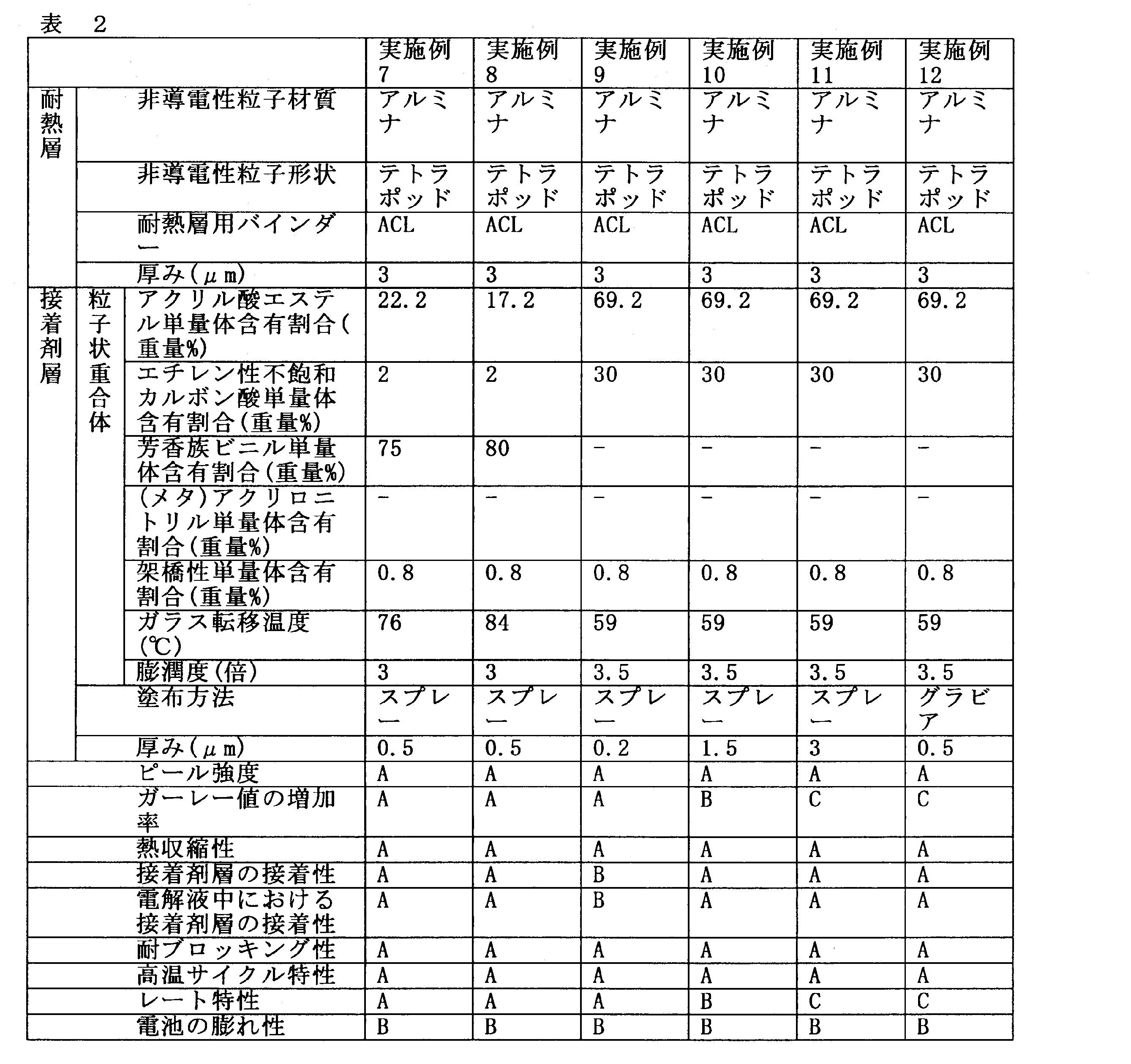

表1~表3から、有機セパレータ層、前記有機セパレータ層の少なくとも一面上に隣接して形成された耐熱層、及び前記耐熱層上に形成された接着剤層を有する二次電池用セパレータであって、前記耐熱層は、非導電性粒子及びバインダーを含有し、前記接着剤層は、ガラス転移温度が10~100℃である粒子状重合体を含む二次電池用セパレータは、実施例1~12に示すように、比較例1~5記載の、接着剤層を用いない二次電池用セパレータと比べて、耐熱性、電極活物質層との接着性及び耐ブロッキング性すべてに優れることがわかる。さらに、上記二次電池用セパレータを有する二次電池は、高温サイクル特性及びレート特性に優れることがわかる。
Claims (7)
- 有機セパレータ層、前記有機セパレータ層の少なくとも一面上に隣接して形成された耐熱層、及び前記耐熱層上に形成された接着剤層を有する二次電池用セパレータであって、
前記耐熱層は、非導電性粒子及びバインダーを含有し、
前記接着剤層は、ガラス転移温度が10~100℃である粒子状重合体を含有する二次電池用セパレータ。 - 前記接着剤層の厚みが0.1~5μmである請求項1に記載の二次電池用セパレータ。
- 前記粒子状重合体が、架橋性単量体単位を含有し、前記粒子状重合体における前記架橋性単量体単位の含有割合が0.1~2重量%である請求項1または2に記載の二次電池用セパレータ。
- エチレンカーボネート(EC)及びジエチルカーボネート(DEC)の容積比がEC:DEC=1:2となるように混合してなる混合溶媒に、LiPF6を1mol/Lの濃度で溶解した指標溶液に対する、前記粒子状重合体の20℃における膨潤度が1.1~15倍である請求項1~3のいずれか一項に記載の二次電池用セパレータ。
- 前記粒子状重合体が、エチレン性不飽和カルボン酸単量体単位を含有し、前記粒子状重合体における前記エチレン性不飽和カルボン酸単量体単位の含有割合が1~50重量%である請求項1~4のいずれか一項に記載の二次電池用セパレータ。
- 有機セパレータ層上に、非導電性粒子及びバインダーを含む耐熱層用スラリーを塗布し、乾燥することにより耐熱層を形成する工程と、
前記耐熱層の上に、ガラス転移温度が10~100℃である粒子状重合体を含む接着剤層用スラリーを塗布し、乾燥することにより接着剤層を形成する工程と、を有する請求項1~5のいずれか一項に記載の二次電池用セパレータの製造方法。 - 正極、負極、セパレータ及び電解液を備え、前記セパレータが、請求項1~5のいずれか一項に記載の二次電池用セパレータである、二次電池。
Priority Applications (6)
| Application Number | Priority Date | Filing Date | Title |
|---|---|---|---|
| EP13772878.8A EP2835844B1 (en) | 2012-04-05 | 2013-04-04 | Separator for secondary cell |
| PL13772878T PL2835844T3 (pl) | 2012-04-05 | 2013-04-04 | Separator do akumulatora |
| US14/389,503 US9941497B2 (en) | 2012-04-05 | 2013-04-04 | Separator for secondary cell |
| JP2014509214A JP6191597B2 (ja) | 2012-04-05 | 2013-04-04 | 二次電池用セパレータ |
| KR1020147027076A KR102165556B1 (ko) | 2012-04-05 | 2013-04-04 | 이차 전지용 세퍼레이터 |
| CN201380018518.1A CN104221184B (zh) | 2012-04-05 | 2013-04-04 | 二次电池用隔板 |
Applications Claiming Priority (2)
| Application Number | Priority Date | Filing Date | Title |
|---|---|---|---|
| JP2012086632 | 2012-04-05 | ||
| JP2012-086632 | 2012-04-05 |
Publications (1)
| Publication Number | Publication Date |
|---|---|
| WO2013151144A1 true WO2013151144A1 (ja) | 2013-10-10 |
Family
ID=49300622
Family Applications (1)
| Application Number | Title | Priority Date | Filing Date |
|---|---|---|---|
| PCT/JP2013/060384 Ceased WO2013151144A1 (ja) | 2012-04-05 | 2013-04-04 | 二次電池用セパレータ |
Country Status (7)
| Country | Link |
|---|---|
| US (1) | US9941497B2 (ja) |
| EP (1) | EP2835844B1 (ja) |
| JP (1) | JP6191597B2 (ja) |
| KR (1) | KR102165556B1 (ja) |
| CN (1) | CN104221184B (ja) |
| PL (1) | PL2835844T3 (ja) |
| WO (1) | WO2013151144A1 (ja) |
Cited By (57)
| Publication number | Priority date | Publication date | Assignee | Title |
|---|---|---|---|---|
| JP2014203583A (ja) * | 2013-04-02 | 2014-10-27 | トヨタ自動車株式会社 | 二次電池および該電池用のセパレータ |
| US20150140310A1 (en) * | 2013-11-13 | 2015-05-21 | R.R. Donnelley & Sons Company | Insulator material composition and method |
| JP2015128059A (ja) * | 2013-11-27 | 2015-07-09 | 旭化成イーマテリアルズ株式会社 | 蓄電デバイス用セパレータ、蓄電デバイス、リチウムイオン二次電池及び共重合体 |
| JP2015130338A (ja) * | 2013-12-31 | 2015-07-16 | 財團法人工業技術研究院Industrial Technology Research Institute | 耐熱層を有するバッテリーと耐熱層の製造方法 |
| JP2015185369A (ja) * | 2014-03-24 | 2015-10-22 | 日本ゼオン株式会社 | 非水系二次電池多孔膜用バインダー、非水系二次電池多孔膜用組成物、非水系二次電池用多孔膜および非水系二次電池 |
| JP2015185515A (ja) * | 2014-03-26 | 2015-10-22 | 日本ゼオン株式会社 | 二次電池多孔膜用組成物、二次電池用多孔膜及び二次電池 |
| JP2015197977A (ja) * | 2014-03-31 | 2015-11-09 | 日産自動車株式会社 | 電気デバイスのセパレータ接合方法、電気デバイスのセパレータ接合装置、および電気デバイス |
| WO2016017066A1 (ja) * | 2014-07-30 | 2016-02-04 | 日本ゼオン株式会社 | 非水系二次電池機能層用組成物、非水系二次電池用機能層付き基材、非水系二次電池用積層体の製造方法および非水系二次電池 |
| WO2016031163A1 (ja) * | 2014-08-28 | 2016-03-03 | 日本ゼオン株式会社 | 非水系二次電池用積層体および非水系二次電池部材の製造方法 |
| JP2016042454A (ja) * | 2014-08-13 | 2016-03-31 | 三星エスディアイ株式会社Samsung SDI Co.,Ltd. | リチウム二次電池用セパレータ、それを採用したリチウム二次電池及びその製造方法 |
| JP2016048670A (ja) * | 2014-08-26 | 2016-04-07 | 日本ゼオン株式会社 | 非水系二次電池多孔膜用バインダー、非水系二次電池多孔膜用組成物、非水系二次電池用多孔膜および非水系二次電池 |
| JP2016072155A (ja) * | 2014-09-30 | 2016-05-09 | 旭化成イーマテリアルズ株式会社 | 蓄電デバイス用セパレータの製造方法 |
| JP2016105398A (ja) * | 2014-11-21 | 2016-06-09 | 三星エスディアイ株式会社Samsung SDI Co., Ltd. | 二次電池用セパレータ(separator)及び二次電池 |
| KR20160078967A (ko) * | 2013-10-31 | 2016-07-05 | 제온 코포레이션 | 리튬 이온 2 차 전지의 바인더용의 입자상 중합체, 접착층 및 다공막 조성물 |
| JP2016122648A (ja) * | 2012-07-26 | 2016-07-07 | 旭化成株式会社 | 蓄電デバイス用セパレータ、積層体、及び多孔膜 |
| KR20160081037A (ko) * | 2014-12-30 | 2016-07-08 | 삼성에스디아이 주식회사 | 리튬 이차 전지용 세퍼레이터 및 이를 포함하는 리튬 이차 전지 |
| JP2016139622A (ja) * | 2016-04-22 | 2016-08-04 | 旭化成株式会社 | 蓄電デバイス用セパレータ、蓄電デバイス及びリチウムイオン二次電池 |
| JP2016154108A (ja) * | 2015-02-20 | 2016-08-25 | 日本ゼオン株式会社 | 非水系二次電池機能層用バインダー組成物、非水系二次電池機能層用スラリー組成物、非水系二次電池用機能層、非水系二次電池およびその製造方法 |
| WO2016152026A1 (ja) * | 2015-03-20 | 2016-09-29 | 日本ゼオン株式会社 | 非水系二次電池機能層用組成物、非水系二次電池用機能層および非水系二次電池 |
| CN106030858A (zh) * | 2014-03-24 | 2016-10-12 | 日本瑞翁株式会社 | 非水二次电池多孔膜用粘合剂、非水二次电池多孔膜用组合物、非水二次电池用多孔膜及非水二次电池 |
| KR20160129033A (ko) | 2014-09-26 | 2016-11-08 | 아사히 가세이 가부시키가이샤 | 축전 디바이스용 세퍼레이터 |
| JP2017004903A (ja) * | 2015-06-16 | 2017-01-05 | 日立マクセル株式会社 | 扁平形非水二次電池の製造方法 |
| KR20170057233A (ko) * | 2014-09-30 | 2017-05-24 | 니폰 제온 가부시키가이샤 | 리튬 이온 이차 전지 다공막용 조성물, 리튬 이온 이차 전지용 다공막 및 리튬 이온 이차 전지 |
| JP2017103091A (ja) * | 2015-12-01 | 2017-06-08 | オートモーティブエナジーサプライ株式会社 | リチウムイオン二次電池 |
| JP2017103030A (ja) * | 2015-11-30 | 2017-06-08 | 日本ゼオン株式会社 | 非水系二次電池用機能層およびその製造方法、並びに、非水系二次電池およびその製造方法 |
| JP2017103027A (ja) * | 2015-11-30 | 2017-06-08 | 日本ゼオン株式会社 | 非水系二次電池およびその製造方法 |
| JP2017103031A (ja) * | 2015-11-30 | 2017-06-08 | 日本ゼオン株式会社 | 非水系二次電池用積層体 |
| JP2017103034A (ja) * | 2015-11-30 | 2017-06-08 | 日本ゼオン株式会社 | 非水系二次電池用機能層の形成方法、および非水系二次電池の製造方法 |
| JP2018510472A (ja) * | 2015-04-02 | 2018-04-12 | エスケー イノベーション カンパニー リミテッドSk Innovation Co.,Ltd. | リチウム二次電池用融着型複合分離膜およびその製造方法 |
| WO2018070448A1 (ja) * | 2016-10-14 | 2018-04-19 | 日本ゼオン株式会社 | 電気化学素子用接着剤組成物、電気化学素子、及び電気化学素子製造方法 |
| US20180123106A1 (en) * | 2015-08-25 | 2018-05-03 | Lg Chem, Ltd. | Complex separator for electrochemical element, comprising bonding layer, and electrochemical element comprising same |
| JP2018133246A (ja) * | 2017-02-16 | 2018-08-23 | 帝人株式会社 | 非水系二次電池用セパレータ及び非水系二次電池 |
| JP2018170281A (ja) * | 2018-05-31 | 2018-11-01 | 旭化成株式会社 | 蓄電デバイス用セパレータ、蓄電デバイス及びリチウムイオン二次電池 |
| US10193119B2 (en) | 2014-06-27 | 2019-01-29 | Zeon Corporation | Composition for non-aqueous secondary battery functional layer, functional layer for non-aqueous secondary battery, and non-aqueous secondary battery |
| WO2019130994A1 (ja) | 2017-12-27 | 2019-07-04 | 帝人株式会社 | 非水系二次電池用セパレータ及び非水系二次電池 |
| WO2019194094A1 (ja) * | 2018-04-06 | 2019-10-10 | 株式会社大阪ソーダ | 蓄電デバイス用セパレータ、蓄電デバイスおよびそれらの製造方法 |
| JP2020001249A (ja) * | 2018-06-27 | 2020-01-09 | 東レ株式会社 | 多孔性フィルム、二次電池用セパレータおよび二次電池 |
| WO2020031614A1 (ja) * | 2018-08-10 | 2020-02-13 | 日本ゼオン株式会社 | 非水系二次電池接着層用スラリー組成物、非水系二次電池用接着層、非水系二次電池用セパレータ、及び非水系二次電池 |
| WO2020105673A1 (ja) | 2018-11-22 | 2020-05-28 | 東レ株式会社 | 多孔性フィルム、二次電池用セパレータおよび二次電池 |
| JP2020522097A (ja) * | 2018-01-05 | 2020-07-27 | エルジー・ケム・リミテッド | ガラス転移温度の相異なるバインダーを含む分離膜及びその製造方法 |
| JPWO2020175292A1 (ja) * | 2019-02-28 | 2020-09-03 | ||
| WO2020246497A1 (ja) | 2019-06-04 | 2020-12-10 | 帝人株式会社 | 非水系二次電池用セパレータ及び非水系二次電池 |
| KR20210132000A (ko) | 2019-02-28 | 2021-11-03 | 니폰 제온 가부시키가이샤 | 전기 화학 소자용 기능층, 전기 화학 소자용 기능층 형성 세퍼레이터, 및 전기 화학 소자 |
| JPWO2020175025A1 (ja) * | 2019-02-26 | 2021-12-23 | 日本ゼオン株式会社 | 非水系二次電池機能層用スラリー組成物、非水系二次電池用セパレータおよび非水系二次電池 |
| KR20220016457A (ko) | 2019-06-03 | 2022-02-09 | 니폰 제온 가부시키가이샤 | 전기 화학 소자용 기능층 형성 세퍼레이터, 및 전기 화학 소자 |
| KR20220086574A (ko) | 2019-10-31 | 2022-06-23 | 니폰 제온 가부시키가이샤 | 전기 화학 소자용 기능층 및 그 제조 방법, 전기 화학 소자용 기능층 형성 세퍼레이터 및 그 제조 방법, 그리고 전기 화학 소자 및 그 제조 방법 |
| JPWO2022181275A1 (ja) * | 2021-02-26 | 2022-09-01 | ||
| KR20230138457A (ko) | 2021-01-29 | 2023-10-05 | 니폰 제온 가부시키가이샤 | 전기 화학 소자 기능층용 조성물, 전기 화학 소자용기능층, 전기 화학 소자용 적층체 및 전기 화학 소자 |
| KR20240006493A (ko) | 2021-05-10 | 2024-01-15 | 도레이 카부시키가이샤 | 다공성 필름, 이차 전지용 세퍼레이터 및 이차 전지 |
| KR20240007116A (ko) | 2021-05-10 | 2024-01-16 | 도레이 카부시키가이샤 | 다공성 필름, 이차 전지용 세퍼레이터 및 이차 전지 |
| KR20240051924A (ko) | 2021-08-31 | 2024-04-22 | 니폰 제온 가부시키가이샤 | 비수계 이차 전지 접착층용 슬러리 조성물, 비수계 이차 전지용 접착층 및 그 제조 방법, 비수계 이차 전지용 부재, 그리고 비수계 이차 전지 |
| KR20240068620A (ko) | 2021-09-30 | 2024-05-17 | 도레이 카부시키가이샤 | 다공성 필름, 이차전지용 세퍼레이터 및 이차전지 |
| KR20240168947A (ko) | 2022-03-31 | 2024-12-02 | 니폰 제온 가부시키가이샤 | 비수계 이차 전지 기능층용 슬러리 조성물, 비수계 이차 전지용 세퍼레이터 및 비수계 이차 전지 |
| KR20240171069A (ko) | 2022-03-31 | 2024-12-06 | 니폰 제온 가부시키가이샤 | 비수계 이차 전지 기능층용 슬러리 조성물 및 그 제조 방법, 비수계 이차 전지용 세퍼레이터, 그리고 비수계 이차 전지 |
| JP2025500540A (ja) * | 2022-01-14 | 2025-01-09 | エルジー エナジー ソリューション リミテッド | 二次電池およびその製造方法 |
| JP2025500563A (ja) * | 2022-01-14 | 2025-01-09 | エルジー エナジー ソリューション リミテッド | 二次電池およびその製造方法 |
| JP7854138B2 (ja) | 2021-02-26 | 2026-05-01 | 日本ゼオン株式会社 | 電気化学素子機能層用組成物、電気化学素子用機能層、電気化学素子用積層体および電気化学素子 |
Families Citing this family (51)
| Publication number | Priority date | Publication date | Assignee | Title |
|---|---|---|---|---|
| WO2014081035A1 (ja) | 2012-11-26 | 2014-05-30 | 日本ゼオン株式会社 | 電極/セパレータ積層体の製造方法およびリチウムイオン二次電池 |
| KR101611404B1 (ko) * | 2014-02-04 | 2016-04-11 | 울산과학기술원 | 리튬이차전지용 분리막 및 그 제조 방법 |
| WO2016179785A1 (zh) * | 2015-05-11 | 2016-11-17 | 宁德时代新能源科技股份有限公司 | 复合隔膜及使用该复合隔膜的锂离子电池 |
| KR101950448B1 (ko) * | 2015-07-10 | 2019-02-20 | 주식회사 엘지화학 | 전극조립체 및 그의 제조방법 |
| KR102063627B1 (ko) * | 2015-08-19 | 2020-02-11 | 주식회사 엘지화학 | 접착층을 구비하고 있는 분리막 및 전극과 분리막 사이에 접착층이 형성되어 있는 전극 적층체 |
| KR101982571B1 (ko) * | 2015-10-08 | 2019-05-27 | 주식회사 엘지화학 | 전극 내 바인더 분포 측정방법 |
| HUE071713T2 (hu) * | 2015-11-11 | 2025-09-28 | Lg Energy Solution Ltd | Elektróda adhezív réteget tartalmazó szeparátor és az azt tartalmazó elektrokémiai eszköz |
| CN105690894B (zh) * | 2016-02-02 | 2018-08-31 | 东莞新能源科技有限公司 | 绝缘胶带及采用该胶带的锂离子电池 |
| KR102228628B1 (ko) * | 2016-03-31 | 2021-03-15 | 주식회사 엘지화학 | 접착층을 포함하는 전기화학소자용 분리막 및 이를 포함하는 전극 조립체 |
| GB201609686D0 (en) * | 2016-06-02 | 2016-07-20 | Qinetiq Ltd | Devices |
| PL3474348T3 (pl) | 2016-06-21 | 2024-03-04 | Zeon Corporation | Kompozycja do warstwy funkcjonalnej do niewodnej baterii akumulatorowej, warstwa funkcjonalna do niewodnej baterii akumulatorowej i niewodna bateria akumulatorowa |
| WO2018030797A1 (ko) * | 2016-08-09 | 2018-02-15 | 주식회사 엘지화학 | 세퍼레이터 및 이를 포함하는 전기화학소자 |
| CN109565017B (zh) * | 2016-08-17 | 2023-03-24 | 日本瑞翁株式会社 | 非水系二次电池功能层用组合物、非水系二次电池用功能层及非水系二次电池 |
| US11394084B2 (en) * | 2016-11-18 | 2022-07-19 | Lg Energy Solution, Ltd. | Separator and electrochemical device including the same |
| US20200052301A1 (en) * | 2017-03-08 | 2020-02-13 | Zeon Corporation | Binder composition for non-aqueous secondary battery functional layers, slurry composition for non-aqueous secondary battery functional layers, non-aqueous secondary battery functional layer, functional layer attached-separator for non-aqueous secondary battery, non-aqueous secondary battery, and method of producing non-aqueous secondary battery |
| JP7031658B2 (ja) * | 2017-03-17 | 2022-03-08 | 日本ゼオン株式会社 | 非水系二次電池機能層用組成物、非水系二次電池用機能層並びに非水系二次電池およびその製造方法 |
| KR20190123280A (ko) * | 2017-03-17 | 2019-10-31 | 니폰 제온 가부시키가이샤 | 비수계 이차 전지용 기능층 및 비수계 이차 전지 |
| KR102461577B1 (ko) | 2017-07-17 | 2022-11-01 | 삼성에스디아이 주식회사 | 이차전지 모듈 |
| CN111095604B (zh) * | 2017-09-28 | 2024-12-31 | 日本瑞翁株式会社 | 非水系二次电池功能层用组合物、非水系二次电池用功能层、非水系二次电池构件及非水系二次电池 |
| JP7381459B2 (ja) * | 2017-10-30 | 2023-11-15 | アーケマ・インコーポレイテッド | リチウムイオンバッテリーセパレーター |
| WO2019146626A1 (ja) | 2018-01-25 | 2019-08-01 | 三菱製紙株式会社 | リチウムイオン電池用セパレータ用塗液及びリチウムイオン電池用セパレータ |
| KR102838498B1 (ko) | 2018-06-27 | 2025-07-25 | 도레이 카부시키가이샤 | 다공성 필름, 이차전지용 세퍼레이터 및 이차전지 |
| JP7327044B2 (ja) * | 2018-09-26 | 2023-08-16 | 東レ株式会社 | 多孔性フィルム、二次電池用セパレータおよび二次電池 |
| KR102651679B1 (ko) * | 2018-10-23 | 2024-03-27 | 에스케이이노베이션 주식회사 | 이차전지용 분리막 및 이를 이용한 전기화학소자 |
| KR102654789B1 (ko) * | 2018-10-23 | 2024-04-05 | 에스케이이노베이션 주식회사 | 이차전지용 분리막 및 이를 이용한 전기화학소자 |
| KR102385925B1 (ko) * | 2018-11-05 | 2022-04-11 | 주식회사 엘지에너지솔루션 | 전기화학소자용 세퍼레이터 및 이를 포함하는 전기화학소자 |
| JP7234941B2 (ja) | 2018-11-22 | 2023-03-08 | 東レ株式会社 | 多孔性フィルム、二次電池用セパレータおよび二次電池 |
| KR102312280B1 (ko) | 2018-12-26 | 2021-10-12 | 삼성에스디아이 주식회사 | 리튬 이차 전지용 분리막 및 이를 포함하는 리튬 이차 전지 |
| KR102342671B1 (ko) * | 2019-01-04 | 2021-12-22 | 삼성에스디아이 주식회사 | 리튬 이차 전지용 분리막 및 이를 포함하는 리튬 이차 전지 |
| JP7079418B2 (ja) * | 2019-06-11 | 2022-06-02 | トヨタ自動車株式会社 | 非水電解質二次電池 |
| US20220311003A1 (en) * | 2019-08-30 | 2022-09-29 | Zeon Corporation | Binder composition for non-aqueous secondary battery heat-resistant layer, slurry composition for non-aqueous secondary battery heat-resistant layer, heat-resistant layer for non-aqueous secondary battery, and non-aqueous secondary battery |
| US12580274B2 (en) * | 2020-01-31 | 2026-03-17 | Zeon Corporation | Laminate for secondary battery and secondary battery |
| US20230058850A1 (en) * | 2020-03-04 | 2023-02-23 | Ningde Amperex Technology Limited | Electrochemical device and electronic device comprising same |
| EP4131620B1 (en) | 2020-03-31 | 2025-03-05 | Toray Industries, Inc. | Porous film, separator for secondary battery, and secondary battery |
| KR20220161301A (ko) * | 2020-03-31 | 2022-12-06 | 니폰 제온 가부시키가이샤 | 전기 화학 소자 기능층용 조성물, 전기 화학 소자용 기능층, 전기 화학 소자용 적층체, 및 전기 화학 소자 |
| KR20220160531A (ko) | 2020-03-31 | 2022-12-06 | 도레이 카부시키가이샤 | 다공성 필름, 2차전지용 세퍼레이터 및 2차전지 |
| CN111446404B (zh) * | 2020-04-02 | 2025-09-09 | 惠州锂威电子科技有限公司 | 一种锂离子电池用隔膜及其制备方法、锂离子电池 |
| US20230198097A1 (en) | 2020-05-22 | 2023-06-22 | Toray Industries, Inc. | Porous film, separator for secondary battery, and secondary battery |
| WO2022019572A1 (ko) * | 2020-07-20 | 2022-01-27 | 주식회사 엘지에너지솔루션 | 이차전지용 세퍼레이터, 이의 제조방법, 이를 포함하는 이차전지의 제조방법 및 이에 의해 제조된 이차전지 |
| US20230282937A1 (en) * | 2020-08-07 | 2023-09-07 | Lg Energy Solution, Ltd. | Separator for secondary battery and secondary battery including the same |
| DE102022107453A1 (de) * | 2021-04-08 | 2022-10-13 | Sk On Co., Ltd. | Elektrode für eine sekundärbatterie und lithium-sekundärbatterie umassend derselben |
| KR102909166B1 (ko) * | 2021-04-08 | 2026-01-06 | 에스케이온 주식회사 | 이차 전지용 전극 및 이를 포함하는 리튬 이차 전지 |
| KR102909163B1 (ko) * | 2021-04-08 | 2026-01-06 | 에스케이온 주식회사 | 이차 전지용 전극 및 이를 포함하는 리튬 이차 전지 |
| KR102573567B1 (ko) * | 2021-05-27 | 2023-09-04 | 더블유스코프코리아 주식회사 | 분리막 코팅 조성물 |
| CN113471625B (zh) * | 2021-06-30 | 2022-08-19 | 无锡恩捷新材料科技有限公司 | 二次电池、电池隔膜以及制备电池隔膜涂层的浆料 |
| CN114335904B (zh) * | 2022-02-28 | 2022-07-12 | 湖南中锂新材料科技有限公司 | 一种锂电池复合隔膜及其制备方法和应用 |
| KR102799124B1 (ko) * | 2022-06-09 | 2025-04-23 | 에스케이이노베이션 주식회사 | 분리막, 이의 제조방법 및 상기 분리막을 포함하는 전기화학소자 |
| CN115224443B (zh) * | 2022-08-12 | 2023-06-30 | 珠海冠宇电池股份有限公司 | 一种隔膜及包括该隔膜的电池 |
| US20260038969A1 (en) * | 2022-11-14 | 2026-02-05 | Lg Energy Solution, Ltd. | Method for manufacturing secondary battery |
| CN118772805A (zh) * | 2023-04-07 | 2024-10-15 | 宁德时代新能源科技股份有限公司 | 二次电池用粘结剂及其制备方法、以及隔膜、电池单体、电池和用电装置 |
| CN121343044A (zh) * | 2024-07-15 | 2026-01-16 | 宁德时代新能源科技股份有限公司 | 交联苯乙烯类有机颗粒及其制备方法、交联苯乙烯类有机颗粒乳液、隔离膜、二次电池单体、电池装置和用电装置 |
Citations (6)
| Publication number | Priority date | Publication date | Assignee | Title |
|---|---|---|---|---|
| WO2010074202A1 (ja) * | 2008-12-26 | 2010-07-01 | 日本ゼオン株式会社 | リチウムイオン二次電池用セパレーター及びリチウムイオン二次電池 |
| JP2011054503A (ja) * | 2009-09-04 | 2011-03-17 | Hitachi Maxell Ltd | 電気化学素子用セパレータ、電気化学素子およびその製造方法 |
| JP4806735B1 (ja) | 2010-03-24 | 2011-11-02 | 帝人株式会社 | ポリオレフィン微多孔膜及びその製造方法、非水系二次電池用セパレータ、並びに非水系二次電池 |
| WO2012020737A1 (ja) * | 2010-08-09 | 2012-02-16 | 日本ゼオン株式会社 | 二次電池用多孔膜、製造方法、及び用途 |
| WO2012029805A1 (ja) * | 2010-08-31 | 2012-03-08 | 日本ゼオン株式会社 | 電池多孔膜用スラリー組成物、二次電池用多孔膜の製造方法、二次電池用多孔膜、二次電池用電極、二次電池用セパレーター及び二次電池 |
| JP2012048932A (ja) * | 2010-08-26 | 2012-03-08 | Hitachi Ltd | リチウムイオン二次電池 |
Family Cites Families (5)
| Publication number | Priority date | Publication date | Assignee | Title |
|---|---|---|---|---|
| JPS486735Y1 (ja) | 1969-04-10 | 1973-02-21 | ||
| US7250472B1 (en) * | 1998-10-26 | 2007-07-31 | Lucite International, Inc. | Acrylic compositions |
| US7318984B2 (en) * | 2002-05-17 | 2008-01-15 | Nitto Denko Corporation | Adhesive composition-supporting separator for battery and electrode/separator laminate obtained by using the same |
| JP4920122B2 (ja) * | 2010-03-23 | 2012-04-18 | 帝人株式会社 | ポリオレフィン微多孔膜、非水系二次電池用セパレータ、非水系二次電池及びポリオレフィン微多孔膜の製造方法 |
| CN102859777B (zh) * | 2010-03-29 | 2015-08-26 | 日本瑞翁株式会社 | 锂离子二次电池 |
-
2013
- 2013-04-04 EP EP13772878.8A patent/EP2835844B1/en active Active
- 2013-04-04 PL PL13772878T patent/PL2835844T3/pl unknown
- 2013-04-04 CN CN201380018518.1A patent/CN104221184B/zh active Active
- 2013-04-04 US US14/389,503 patent/US9941497B2/en active Active
- 2013-04-04 KR KR1020147027076A patent/KR102165556B1/ko active Active
- 2013-04-04 WO PCT/JP2013/060384 patent/WO2013151144A1/ja not_active Ceased
- 2013-04-04 JP JP2014509214A patent/JP6191597B2/ja active Active
Patent Citations (6)
| Publication number | Priority date | Publication date | Assignee | Title |
|---|---|---|---|---|
| WO2010074202A1 (ja) * | 2008-12-26 | 2010-07-01 | 日本ゼオン株式会社 | リチウムイオン二次電池用セパレーター及びリチウムイオン二次電池 |
| JP2011054503A (ja) * | 2009-09-04 | 2011-03-17 | Hitachi Maxell Ltd | 電気化学素子用セパレータ、電気化学素子およびその製造方法 |
| JP4806735B1 (ja) | 2010-03-24 | 2011-11-02 | 帝人株式会社 | ポリオレフィン微多孔膜及びその製造方法、非水系二次電池用セパレータ、並びに非水系二次電池 |
| WO2012020737A1 (ja) * | 2010-08-09 | 2012-02-16 | 日本ゼオン株式会社 | 二次電池用多孔膜、製造方法、及び用途 |
| JP2012048932A (ja) * | 2010-08-26 | 2012-03-08 | Hitachi Ltd | リチウムイオン二次電池 |
| WO2012029805A1 (ja) * | 2010-08-31 | 2012-03-08 | 日本ゼオン株式会社 | 電池多孔膜用スラリー組成物、二次電池用多孔膜の製造方法、二次電池用多孔膜、二次電池用電極、二次電池用セパレーター及び二次電池 |
Non-Patent Citations (2)
| Title |
|---|
| "VII Solubility Parameter Values", 1989, JOHN WILEY & SONS, article "Polymer Handbook", pages: 519 - 559 |
| See also references of EP2835844A4 |
Cited By (105)
| Publication number | Priority date | Publication date | Assignee | Title |
|---|---|---|---|---|
| US10153473B2 (en) | 2012-07-26 | 2018-12-11 | Asahi Kasei E-Materials Corporation | Separator for electricity storage device, laminate and porous film |
| US10811659B2 (en) | 2012-07-26 | 2020-10-20 | Asahi Kasei E-Materials Corporation | Separator for electricity storage device, laminate and porous film |
| JP2016122648A (ja) * | 2012-07-26 | 2016-07-07 | 旭化成株式会社 | 蓄電デバイス用セパレータ、積層体、及び多孔膜 |
| JP2014203583A (ja) * | 2013-04-02 | 2014-10-27 | トヨタ自動車株式会社 | 二次電池および該電池用のセパレータ |
| KR102301045B1 (ko) * | 2013-10-31 | 2021-09-09 | 제온 코포레이션 | 리튬 이온 2 차 전지의 바인더용의 입자상 중합체, 접착층 및 다공막 조성물 |
| KR20160078967A (ko) * | 2013-10-31 | 2016-07-05 | 제온 코포레이션 | 리튬 이온 2 차 전지의 바인더용의 입자상 중합체, 접착층 및 다공막 조성물 |
| US11152667B2 (en) | 2013-10-31 | 2021-10-19 | Zeon Corporation | Particulate polymer for use in binder for lithium-ion secondary battery; adhesive layer; and porous-membrane composition |
| US10106710B2 (en) * | 2013-11-13 | 2018-10-23 | R.R. Donnelley & Sons Company | Insulator material composition and method |
| US9718997B2 (en) | 2013-11-13 | 2017-08-01 | R.R. Donnelley & Sons Company | Battery |
| US20150140310A1 (en) * | 2013-11-13 | 2015-05-21 | R.R. Donnelley & Sons Company | Insulator material composition and method |
| JP2015128059A (ja) * | 2013-11-27 | 2015-07-09 | 旭化成イーマテリアルズ株式会社 | 蓄電デバイス用セパレータ、蓄電デバイス、リチウムイオン二次電池及び共重合体 |
| JP2016033921A (ja) * | 2013-11-27 | 2016-03-10 | 旭化成イーマテリアルズ株式会社 | 蓄電デバイス用セパレータ、蓄電デバイス及びリチウムイオン二次電池 |
| JP2016201367A (ja) * | 2013-11-27 | 2016-12-01 | 旭化成株式会社 | 蓄電デバイス用セパレータ、蓄電デバイス、リチウムイオン二次電池及び共重合体 |
| TWI613851B (zh) * | 2013-12-31 | 2018-02-01 | 財團法人工業技術研究院 | 具有熱阻隔層之電池及此熱阻隔層之製造方法 |
| JP2015130338A (ja) * | 2013-12-31 | 2015-07-16 | 財團法人工業技術研究院Industrial Technology Research Institute | 耐熱層を有するバッテリーと耐熱層の製造方法 |
| JP2015185369A (ja) * | 2014-03-24 | 2015-10-22 | 日本ゼオン株式会社 | 非水系二次電池多孔膜用バインダー、非水系二次電池多孔膜用組成物、非水系二次電池用多孔膜および非水系二次電池 |
| CN106030858B (zh) * | 2014-03-24 | 2019-08-30 | 日本瑞翁株式会社 | 非水二次电池多孔膜用粘合剂、非水二次电池多孔膜用组合物、非水二次电池用多孔膜及非水二次电池 |
| US11807698B2 (en) | 2014-03-24 | 2023-11-07 | Zeon Corporation | Binder for non-aqueous secondary battery porous membrane-use, composition for non-aqueous secondary battery porous membrane-use, porous membrane for non-aqueous secondary battery-use, and non-aqueous secondary battery |
| CN106030858A (zh) * | 2014-03-24 | 2016-10-12 | 日本瑞翁株式会社 | 非水二次电池多孔膜用粘合剂、非水二次电池多孔膜用组合物、非水二次电池用多孔膜及非水二次电池 |
| JP2015185515A (ja) * | 2014-03-26 | 2015-10-22 | 日本ゼオン株式会社 | 二次電池多孔膜用組成物、二次電池用多孔膜及び二次電池 |
| JP2015197977A (ja) * | 2014-03-31 | 2015-11-09 | 日産自動車株式会社 | 電気デバイスのセパレータ接合方法、電気デバイスのセパレータ接合装置、および電気デバイス |
| US10193119B2 (en) | 2014-06-27 | 2019-01-29 | Zeon Corporation | Composition for non-aqueous secondary battery functional layer, functional layer for non-aqueous secondary battery, and non-aqueous secondary battery |
| WO2016017066A1 (ja) * | 2014-07-30 | 2016-02-04 | 日本ゼオン株式会社 | 非水系二次電池機能層用組成物、非水系二次電池用機能層付き基材、非水系二次電池用積層体の製造方法および非水系二次電池 |
| KR20170039620A (ko) | 2014-07-30 | 2017-04-11 | 니폰 제온 가부시키가이샤 | 비수계 이차 전지 기능층용 조성물, 비수계 이차 전지용 기능층을 갖는 기재, 비수계 이차 전지용 적층체의 제조 방법 및 비수계 이차 전지 |
| JPWO2016017066A1 (ja) * | 2014-07-30 | 2017-04-27 | 日本ゼオン株式会社 | 非水系二次電池機能層用組成物、非水系二次電池用機能層付き基材、非水系二次電池用積層体の製造方法および非水系二次電池 |
| US10177362B2 (en) | 2014-07-30 | 2019-01-08 | Zeon Corporation | Composition for non-aqueous secondary battery functional layer, functional layer-equipped substrate for non-aqueous secondary battery, method for producing laminate for non-aqueous secondary battery, and non-aqueous secondary battery |
| US10217985B2 (en) | 2014-08-13 | 2019-02-26 | Samsung Sdi Co., Ltd. | Separator for lithium secondary battery, lithium secondary battery using the separator, and method of manufacturing the lithium secondary battery |
| JP2016042454A (ja) * | 2014-08-13 | 2016-03-31 | 三星エスディアイ株式会社Samsung SDI Co.,Ltd. | リチウム二次電池用セパレータ、それを採用したリチウム二次電池及びその製造方法 |
| JP2016048670A (ja) * | 2014-08-26 | 2016-04-07 | 日本ゼオン株式会社 | 非水系二次電池多孔膜用バインダー、非水系二次電池多孔膜用組成物、非水系二次電池用多孔膜および非水系二次電池 |
| WO2016031163A1 (ja) * | 2014-08-28 | 2016-03-03 | 日本ゼオン株式会社 | 非水系二次電池用積層体および非水系二次電池部材の製造方法 |
| JPWO2016031163A1 (ja) * | 2014-08-28 | 2017-06-08 | 日本ゼオン株式会社 | 非水系二次電池用積層体および非水系二次電池部材の製造方法 |
| KR20170044640A (ko) | 2014-08-28 | 2017-04-25 | 니폰 제온 가부시키가이샤 | 비수계 이차 전지용 적층체 및 비수계 이차 전지 부재의 제조 방법 |
| US10186699B2 (en) | 2014-08-28 | 2019-01-22 | Zeon Corporation | Laminate for non-aqueous secondary battery, and method for manufacturing non-aqueous secondary battery member |
| US10361415B2 (en) | 2014-09-26 | 2019-07-23 | Asahi Kasei Kabushiki Kaisha | Separator for electricity storage device |
| KR20160129033A (ko) | 2014-09-26 | 2016-11-08 | 아사히 가세이 가부시키가이샤 | 축전 디바이스용 세퍼레이터 |
| KR102424200B1 (ko) * | 2014-09-30 | 2022-07-21 | 니폰 제온 가부시키가이샤 | 리튬 이온 이차 전지 다공막용 조성물, 리튬 이온 이차 전지용 다공막 및 리튬 이온 이차 전지 |
| JP2016072155A (ja) * | 2014-09-30 | 2016-05-09 | 旭化成イーマテリアルズ株式会社 | 蓄電デバイス用セパレータの製造方法 |
| KR20170057233A (ko) * | 2014-09-30 | 2017-05-24 | 니폰 제온 가부시키가이샤 | 리튬 이온 이차 전지 다공막용 조성물, 리튬 이온 이차 전지용 다공막 및 리튬 이온 이차 전지 |
| JP2016105398A (ja) * | 2014-11-21 | 2016-06-09 | 三星エスディアイ株式会社Samsung SDI Co., Ltd. | 二次電池用セパレータ(separator)及び二次電池 |
| KR20160081037A (ko) * | 2014-12-30 | 2016-07-08 | 삼성에스디아이 주식회사 | 리튬 이차 전지용 세퍼레이터 및 이를 포함하는 리튬 이차 전지 |
| KR101709697B1 (ko) | 2014-12-30 | 2017-02-23 | 삼성에스디아이 주식회사 | 리튬 이차 전지용 세퍼레이터 및 이를 포함하는 리튬 이차 전지 |
| JP2016154108A (ja) * | 2015-02-20 | 2016-08-25 | 日本ゼオン株式会社 | 非水系二次電池機能層用バインダー組成物、非水系二次電池機能層用スラリー組成物、非水系二次電池用機能層、非水系二次電池およびその製造方法 |
| CN107431169A (zh) * | 2015-03-20 | 2017-12-01 | 日本瑞翁株式会社 | 非水系二次电池功能层用组合物、非水系二次电池用功能层以及非水系二次电池 |
| WO2016152026A1 (ja) * | 2015-03-20 | 2016-09-29 | 日本ゼオン株式会社 | 非水系二次電池機能層用組成物、非水系二次電池用機能層および非水系二次電池 |
| US11289739B2 (en) | 2015-03-20 | 2022-03-29 | Zeon Corporation | Composition for non-aqueous secondary battery functional layer, non-aqueous secondary battery functional layer, and non-aqueous secondary battery |
| JPWO2016152026A1 (ja) * | 2015-03-20 | 2017-12-28 | 日本ゼオン株式会社 | 非水系二次電池機能層用組成物、非水系二次電池用機能層および非水系二次電池 |
| JP7073105B2 (ja) | 2015-04-02 | 2022-05-23 | エスケー イノベーション カンパニー リミテッド | リチウム二次電池用融着型複合分離膜およびその製造方法 |
| US10985356B2 (en) | 2015-04-02 | 2021-04-20 | Sk Innovation Co., Ltd. | Composite separation membrane for lithium secondary battery and manufacturing method therefor |
| JP2018510472A (ja) * | 2015-04-02 | 2018-04-12 | エスケー イノベーション カンパニー リミテッドSk Innovation Co.,Ltd. | リチウム二次電池用融着型複合分離膜およびその製造方法 |
| JP2017004903A (ja) * | 2015-06-16 | 2017-01-05 | 日立マクセル株式会社 | 扁平形非水二次電池の製造方法 |
| US10777801B2 (en) * | 2015-08-25 | 2020-09-15 | Lg Chem, Ltd. | Complex separator for electrochemical element, comprising bonding layer, and electrochemical element comprising same |
| US20180123106A1 (en) * | 2015-08-25 | 2018-05-03 | Lg Chem, Ltd. | Complex separator for electrochemical element, comprising bonding layer, and electrochemical element comprising same |
| JP2017103030A (ja) * | 2015-11-30 | 2017-06-08 | 日本ゼオン株式会社 | 非水系二次電池用機能層およびその製造方法、並びに、非水系二次電池およびその製造方法 |
| JP2017103034A (ja) * | 2015-11-30 | 2017-06-08 | 日本ゼオン株式会社 | 非水系二次電池用機能層の形成方法、および非水系二次電池の製造方法 |
| JP2017103031A (ja) * | 2015-11-30 | 2017-06-08 | 日本ゼオン株式会社 | 非水系二次電池用積層体 |
| JP2017103027A (ja) * | 2015-11-30 | 2017-06-08 | 日本ゼオン株式会社 | 非水系二次電池およびその製造方法 |
| JP2017103091A (ja) * | 2015-12-01 | 2017-06-08 | オートモーティブエナジーサプライ株式会社 | リチウムイオン二次電池 |
| JP2016139622A (ja) * | 2016-04-22 | 2016-08-04 | 旭化成株式会社 | 蓄電デバイス用セパレータ、蓄電デバイス及びリチウムイオン二次電池 |
| JP6996513B2 (ja) | 2016-10-14 | 2022-01-17 | 日本ゼオン株式会社 | 電気化学素子用接着剤組成物、電気化学素子、及び電気化学素子製造方法 |
| JPWO2018070448A1 (ja) * | 2016-10-14 | 2019-08-08 | 日本ゼオン株式会社 | 電気化学素子用接着剤組成物、電気化学素子、及び電気化学素子製造方法 |
| WO2018070448A1 (ja) * | 2016-10-14 | 2018-04-19 | 日本ゼオン株式会社 | 電気化学素子用接着剤組成物、電気化学素子、及び電気化学素子製造方法 |
| JP2018133246A (ja) * | 2017-02-16 | 2018-08-23 | 帝人株式会社 | 非水系二次電池用セパレータ及び非水系二次電池 |
| US12074339B2 (en) | 2017-12-27 | 2024-08-27 | Teijin Limited | Separator including porous substrate, heat resistant porous layer, and adhesive layer, and non-aqueous secondary battery including the same |
| WO2019130994A1 (ja) | 2017-12-27 | 2019-07-04 | 帝人株式会社 | 非水系二次電池用セパレータ及び非水系二次電池 |
| KR20200102437A (ko) | 2017-12-27 | 2020-08-31 | 데이진 가부시키가이샤 | 비수계 이차 전지용 세퍼레이터 및 비수계 이차 전지 |
| JP2020522097A (ja) * | 2018-01-05 | 2020-07-27 | エルジー・ケム・リミテッド | ガラス転移温度の相異なるバインダーを含む分離膜及びその製造方法 |
| US11189885B2 (en) | 2018-01-05 | 2021-11-30 | Lg Chem, Ltd. | Separator including binders having different glass transition temperatures and method of manufacturing the same |
| JPWO2019194094A1 (ja) * | 2018-04-06 | 2021-04-22 | 株式会社大阪ソーダ | 蓄電デバイス用セパレータ、蓄電デバイスおよびそれらの製造方法 |
| JP7359137B2 (ja) | 2018-04-06 | 2023-10-11 | 株式会社大阪ソーダ | 蓄電デバイス用セパレータ、蓄電デバイスおよびそれらの製造方法 |
| WO2019194094A1 (ja) * | 2018-04-06 | 2019-10-10 | 株式会社大阪ソーダ | 蓄電デバイス用セパレータ、蓄電デバイスおよびそれらの製造方法 |
| JP2018170281A (ja) * | 2018-05-31 | 2018-11-01 | 旭化成株式会社 | 蓄電デバイス用セパレータ、蓄電デバイス及びリチウムイオン二次電池 |
| JP7176249B2 (ja) | 2018-06-27 | 2022-11-22 | 東レ株式会社 | 多孔性フィルム、二次電池用セパレータおよび二次電池 |
| JP2020001249A (ja) * | 2018-06-27 | 2020-01-09 | 東レ株式会社 | 多孔性フィルム、二次電池用セパレータおよび二次電池 |
| JPWO2020031614A1 (ja) * | 2018-08-10 | 2021-08-12 | 日本ゼオン株式会社 | 非水系二次電池接着層用スラリー組成物、非水系二次電池用接着層、非水系二次電池用セパレータ、及び非水系二次電池 |
| WO2020031614A1 (ja) * | 2018-08-10 | 2020-02-13 | 日本ゼオン株式会社 | 非水系二次電池接着層用スラリー組成物、非水系二次電池用接着層、非水系二次電池用セパレータ、及び非水系二次電池 |
| JP7501363B2 (ja) | 2018-08-10 | 2024-06-18 | 日本ゼオン株式会社 | 非水系二次電池接着層用スラリー組成物、非水系二次電池用接着層、非水系二次電池用セパレータ、及び非水系二次電池 |
| KR20210092191A (ko) | 2018-11-22 | 2021-07-23 | 도레이 카부시키가이샤 | 다공성 필름, 이차전지용 세퍼레이터 및 이차전지 |
| WO2020105673A1 (ja) | 2018-11-22 | 2020-05-28 | 東レ株式会社 | 多孔性フィルム、二次電池用セパレータおよび二次電池 |
| JP7552578B2 (ja) | 2019-02-26 | 2024-09-18 | 日本ゼオン株式会社 | 非水系二次電池機能層用スラリー組成物、非水系二次電池用セパレータおよび非水系二次電池 |
| JPWO2020175025A1 (ja) * | 2019-02-26 | 2021-12-23 | 日本ゼオン株式会社 | 非水系二次電池機能層用スラリー組成物、非水系二次電池用セパレータおよび非水系二次電池 |
| JP7552579B2 (ja) | 2019-02-28 | 2024-09-18 | 日本ゼオン株式会社 | 電気化学素子機能層用組成物、電気化学素子用機能層及び電気化学素子 |
| JPWO2020175292A1 (ja) * | 2019-02-28 | 2020-09-03 | ||
| KR20260003393A (ko) | 2019-02-28 | 2026-01-06 | 니폰 제온 가부시키가이샤 | 전기 화학 소자용 기능층, 전기 화학 소자용 기능층 형성 세퍼레이터, 및 전기 화학 소자 |
| US12100861B2 (en) | 2019-02-28 | 2024-09-24 | Zeon Corporation | Functional layer for electrochemical device, functional layer-equipped separator for electrochemical device, and electrochemical device |
| KR20210132000A (ko) | 2019-02-28 | 2021-11-03 | 니폰 제온 가부시키가이샤 | 전기 화학 소자용 기능층, 전기 화학 소자용 기능층 형성 세퍼레이터, 및 전기 화학 소자 |
| KR20210127925A (ko) | 2019-02-28 | 2021-10-25 | 니폰 제온 가부시키가이샤 | 전기 화학 소자 기능층용 조성물, 전기 화학 소자용 기능층 및 전기 화학 소자 |
| KR20220016457A (ko) | 2019-06-03 | 2022-02-09 | 니폰 제온 가부시키가이샤 | 전기 화학 소자용 기능층 형성 세퍼레이터, 및 전기 화학 소자 |
| US12362430B2 (en) | 2019-06-03 | 2025-07-15 | Zeon Corporation | Functional layer-equipped separator for electrochemical device and electrochemical device |
| EP4235891A2 (en) | 2019-06-04 | 2023-08-30 | Teijin Limited | Separator for non-aqueous secondary battery, and non-aqueous secondary battery |
| WO2020246497A1 (ja) | 2019-06-04 | 2020-12-10 | 帝人株式会社 | 非水系二次電池用セパレータ及び非水系二次電池 |
| CN113678312A (zh) * | 2019-06-04 | 2021-11-19 | 帝人株式会社 | 非水系二次电池用隔膜及非水系二次电池 |
| KR20210136100A (ko) | 2019-06-04 | 2021-11-16 | 데이진 가부시키가이샤 | 비수계 이차전지용 세퍼레이터 및 비수계 이차전지 |
| JPWO2020246497A1 (ja) * | 2019-06-04 | 2021-09-13 | 帝人株式会社 | 非水系二次電池用セパレータ及び非水系二次電池 |
| KR20220086574A (ko) | 2019-10-31 | 2022-06-23 | 니폰 제온 가부시키가이샤 | 전기 화학 소자용 기능층 및 그 제조 방법, 전기 화학 소자용 기능층 형성 세퍼레이터 및 그 제조 방법, 그리고 전기 화학 소자 및 그 제조 방법 |
| KR20230138457A (ko) | 2021-01-29 | 2023-10-05 | 니폰 제온 가부시키가이샤 | 전기 화학 소자 기능층용 조성물, 전기 화학 소자용기능층, 전기 화학 소자용 적층체 및 전기 화학 소자 |
| JP7854138B2 (ja) | 2021-02-26 | 2026-05-01 | 日本ゼオン株式会社 | 電気化学素子機能層用組成物、電気化学素子用機能層、電気化学素子用積層体および電気化学素子 |
| JPWO2022181275A1 (ja) * | 2021-02-26 | 2022-09-01 | ||
| KR20240006493A (ko) | 2021-05-10 | 2024-01-15 | 도레이 카부시키가이샤 | 다공성 필름, 이차 전지용 세퍼레이터 및 이차 전지 |
| KR20240007116A (ko) | 2021-05-10 | 2024-01-16 | 도레이 카부시키가이샤 | 다공성 필름, 이차 전지용 세퍼레이터 및 이차 전지 |
| KR20240051924A (ko) | 2021-08-31 | 2024-04-22 | 니폰 제온 가부시키가이샤 | 비수계 이차 전지 접착층용 슬러리 조성물, 비수계 이차 전지용 접착층 및 그 제조 방법, 비수계 이차 전지용 부재, 그리고 비수계 이차 전지 |
| KR20240068620A (ko) | 2021-09-30 | 2024-05-17 | 도레이 카부시키가이샤 | 다공성 필름, 이차전지용 세퍼레이터 및 이차전지 |
| JP2025500540A (ja) * | 2022-01-14 | 2025-01-09 | エルジー エナジー ソリューション リミテッド | 二次電池およびその製造方法 |
| JP2025500563A (ja) * | 2022-01-14 | 2025-01-09 | エルジー エナジー ソリューション リミテッド | 二次電池およびその製造方法 |
| KR20240171069A (ko) | 2022-03-31 | 2024-12-06 | 니폰 제온 가부시키가이샤 | 비수계 이차 전지 기능층용 슬러리 조성물 및 그 제조 방법, 비수계 이차 전지용 세퍼레이터, 그리고 비수계 이차 전지 |
| KR20240168947A (ko) | 2022-03-31 | 2024-12-02 | 니폰 제온 가부시키가이샤 | 비수계 이차 전지 기능층용 슬러리 조성물, 비수계 이차 전지용 세퍼레이터 및 비수계 이차 전지 |
Also Published As
| Publication number | Publication date |
|---|---|
| JP6191597B2 (ja) | 2017-09-06 |
| CN104221184B (zh) | 2016-10-05 |
| JPWO2013151144A1 (ja) | 2015-12-17 |
| PL2835844T3 (pl) | 2019-04-30 |
| EP2835844B1 (en) | 2018-11-14 |
| EP2835844A1 (en) | 2015-02-11 |
| EP2835844A4 (en) | 2015-12-23 |
| KR102165556B1 (ko) | 2020-10-14 |
| US20150333308A1 (en) | 2015-11-19 |
| US9941497B2 (en) | 2018-04-10 |
| KR20150002629A (ko) | 2015-01-07 |
| CN104221184A (zh) | 2014-12-17 |
Similar Documents
| Publication | Publication Date | Title |
|---|---|---|
| JP6191597B2 (ja) | 二次電池用セパレータ | |
| JP5549739B2 (ja) | 二次電池多孔膜スラリー、二次電池多孔膜、二次電池電極、二次電池セパレーター及び二次電池 | |
| JP6149730B2 (ja) | 二次電池用正極及びその製造方法、スラリー組成物、並びに二次電池 | |
| JP6375949B2 (ja) | 二次電池用正極の製造方法、二次電池及び二次電池用積層体の製造方法 | |
| JP5605591B2 (ja) | 二次電池多孔膜スラリー、二次電池多孔膜、二次電池電極、二次電池セパレーター、二次電池、及び二次電池多孔膜の製造方法 | |
| JP5522422B2 (ja) | 二次電池多孔膜スラリー、二次電池多孔膜、二次電池電極、二次電池セパレーター及び二次電池 | |
| JP6052290B2 (ja) | リチウムイオン二次電池電極用のスラリー組成物、リチウムイオン二次電池用電極及びリチウムイオン二次電池 | |
| JP2014149936A (ja) | 二次電池用セパレータ、二次電池用セパレータの製造方法及び二次電池 | |
| JP5652572B2 (ja) | 二次電池用多孔膜及びその製造方法、二次電池用電極、二次電池用セパレーター並びに二次電池 | |
| JP2014149935A (ja) | 二次電池用セパレータ、二次電池用セパレータの製造方法及び二次電池 | |
| JP5751414B2 (ja) | 二次電池多孔膜用スラリー組成物 | |
| JP6327251B2 (ja) | リチウムイオン二次電池用多孔膜スラリー組成物、リチウムイオン二次電池用セパレーター、リチウムイオン二次電池用電極及びリチウムイオン二次電池 | |
| JP5978837B2 (ja) | リチウムイオン二次電池電極用のスラリー組成物、リチウムイオン二次電池用電極及びリチウムイオン二次電池 | |
| JP5682557B2 (ja) | 二次電池用正極及び二次電池 | |
| JPWO2013141140A1 (ja) | 二次電池用多孔膜及びその製造方法、二次電池用電極、二次電池用セパレーター並びに二次電池 | |
| JP2014146471A (ja) | 二次電池負極用スラリー組成物、その製造方法、二次電池用負極、及び二次電池 | |
| JP6236964B2 (ja) | リチウムイオン二次電池用多孔膜組成物、リチウムイオン二次電池用セパレーター、リチウムイオン二次電池用電極、及びリチウムイオン二次電池 | |
| JP2014203805A (ja) | リチウムイオン二次電池負極用粒子状バインダー、リチウムイオン二次電池負極用スラリー組成物およびリチウムイオン二次電池 |
Legal Events
| Date | Code | Title | Description |
|---|---|---|---|
| 121 | Ep: the epo has been informed by wipo that ep was designated in this application |
Ref document number: 13772878 Country of ref document: EP Kind code of ref document: A1 |
|
| ENP | Entry into the national phase |
Ref document number: 2014509214 Country of ref document: JP Kind code of ref document: A |
|
| ENP | Entry into the national phase |
Ref document number: 20147027076 Country of ref document: KR Kind code of ref document: A |
|
| WWE | Wipo information: entry into national phase |
Ref document number: 14389503 Country of ref document: US |
|
| WWE | Wipo information: entry into national phase |
Ref document number: 2013772878 Country of ref document: EP |
|
| NENP | Non-entry into the national phase |
Ref country code: DE |