WO2013153575A1 - Moteur électrique - Google Patents
Moteur électrique Download PDFInfo
- Publication number
- WO2013153575A1 WO2013153575A1 PCT/JP2012/002486 JP2012002486W WO2013153575A1 WO 2013153575 A1 WO2013153575 A1 WO 2013153575A1 JP 2012002486 W JP2012002486 W JP 2012002486W WO 2013153575 A1 WO2013153575 A1 WO 2013153575A1
- Authority
- WO
- WIPO (PCT)
- Prior art keywords
- magnetic body
- partition wall
- electric motor
- magnetic
- rotor
- Prior art date
- Legal status (The legal status is an assumption and is not a legal conclusion. Google has not performed a legal analysis and makes no representation as to the accuracy of the status listed.)
- Ceased
Links
Images


Classifications
-
- H—ELECTRICITY
- H02—GENERATION; CONVERSION OR DISTRIBUTION OF ELECTRIC POWER
- H02K—DYNAMO-ELECTRIC MACHINES
- H02K1/00—Details of the magnetic circuit
- H02K1/06—Details of the magnetic circuit characterised by the shape, form or construction
- H02K1/22—Rotating parts of the magnetic circuit
- H02K1/27—Rotor cores with permanent magnets
- H02K1/2706—Inner rotors
- H02K1/272—Inner rotors the magnetisation axis of the magnets being perpendicular to the rotor axis
- H02K1/2726—Inner rotors the magnetisation axis of the magnets being perpendicular to the rotor axis the rotor consisting of a single magnet or two or more axially juxtaposed single magnets
-
- H—ELECTRICITY
- H02—GENERATION; CONVERSION OR DISTRIBUTION OF ELECTRIC POWER
- H02K—DYNAMO-ELECTRIC MACHINES
- H02K1/00—Details of the magnetic circuit
- H02K1/06—Details of the magnetic circuit characterised by the shape, form or construction
- H02K1/22—Rotating parts of the magnetic circuit
- H02K1/24—Rotor cores with salient poles ; Variable reluctance rotors
- H02K1/246—Variable reluctance rotors
-
- H—ELECTRICITY
- H02—GENERATION; CONVERSION OR DISTRIBUTION OF ELECTRIC POWER
- H02K—DYNAMO-ELECTRIC MACHINES
- H02K19/00—Synchronous motors or generators
- H02K19/02—Synchronous motors
- H02K19/10—Synchronous motors for multi-phase current
- H02K19/103—Motors having windings on the stator and a variable reluctance soft-iron rotor without windings
-
- H—ELECTRICITY
- H02—GENERATION; CONVERSION OR DISTRIBUTION OF ELECTRIC POWER
- H02K—DYNAMO-ELECTRIC MACHINES
- H02K21/00—Synchronous motors having permanent magnets; Synchronous generators having permanent magnets
- H02K21/38—Synchronous motors having permanent magnets; Synchronous generators having permanent magnets with rotating flux distributors, and armatures and magnets both stationary
- H02K21/44—Synchronous motors having permanent magnets; Synchronous generators having permanent magnets with rotating flux distributors, and armatures and magnets both stationary with armature windings wound upon the magnets
-
- H—ELECTRICITY
- H02—GENERATION; CONVERSION OR DISTRIBUTION OF ELECTRIC POWER
- H02K—DYNAMO-ELECTRIC MACHINES
- H02K2201/00—Specific aspects not provided for in the other groups of this subclass relating to the magnetic circuits
- H02K2201/12—Transversal flux machines
-
- H—ELECTRICITY
- H02—GENERATION; CONVERSION OR DISTRIBUTION OF ELECTRIC POWER
- H02K—DYNAMO-ELECTRIC MACHINES
- H02K2205/00—Specific aspects not provided for in the other groups of this subclass relating to casings, enclosures, supports
- H02K2205/12—Machines characterised by means for reducing windage losses or windage noise
Definitions
- the present invention relates to a magnetic inductor type electric motor in which a rotor core is made of a magnetic material such as iron.
- An electric motor for rotating a turbine such as an electric compressor and an electric assist turbo is required to have a low inertia and a high torque because a short acceleration time and a high speed rotation are required.
- the rotor having the first and second magnetic bodies arranged on the rotation shaft with the salient poles shifted is closely interposed between the first and second magnetic bodies.
- the torque is generated by switching the energization to the torque generating drive coil and switching between the S pole and the N pole.
- Patent Document 1 there is a merit of reducing the windage loss and improving the torque by providing the partition walls, but there is a problem that the volume of the rotor is increased by the amount of the partition walls and the inertia is increased in a trade-off manner.
- the present invention has been made to solve the above-described problems, and an object of the present invention is to provide an electric motor having reduced inertia without impairing the effect of reducing the windage loss of the partition wall.
- the electric motor according to the present invention includes a first magnetic body having salient poles protruding at an equiangular pitch in the circumferential direction on an outer periphery of a cylindrical base portion having a rotation shaft insertion hole at an axial center position, and the first magnetic body and the first magnetic body.
- a plate-shaped member having the same shape and having a salient pole shifted from each other in the circumferential direction and coaxially disposed at a predetermined interval in the axial direction and a rotary shaft insertion hole.
- a rotor having a partition wall interposed between the magnetic body and the second magnetic body in close contact with each other, and a rotation in which the first magnetic body, the second magnetic body, and the partition wall are inserted into the respective rotation shaft insertion holes and fixed.
- a shaft a stator iron core that surrounds each of the first magnetic body and the second magnetic body, a field magnetomotive force generating section that excites the salient poles of the rotor, and a torque generating drive section that generates rotational torque in the rotor
- the partition wall is disposed at a position shifted in the axial direction. Besides site sandwiched 1 and magnetic material salient pole and the salient pole of the second magnetic body, in which holes or notches are formed.
- the volume can be reduced and the inertia can be reduced.
- there is a partition wall between the salient poles of the first magnetic body and the salient poles of the second magnetic body, which are disposed at positions shifted in the axial direction there is a gap between the salient poles.
- the axial airflow flowing from the first magnetic body to the second magnetic body through the first magnetic body can be blocked, and windage loss can be reduced. Therefore, an electric motor with reduced inertia can be provided without impairing the windage loss reducing effect of the partition wall.
- FIG.2 (a) is a perspective view of a rotor
- FIG.2 (b) is a top view of a partition
- FIG. 3A is a perspective view of a rotor
- FIG. 3B is a plan view of a partition wall, showing an example of a conventional rotor. It is a graph which shows the result of having measured torque / inertia ratio using the partition from which a shape differs.
- FIG.5 (a) is a perspective view of a rotor
- FIG.5 (b) is a top view of a partition
- FIG. 6A is a perspective view of a rotor
- FIG. 6B is a plan view of the partition wall, showing a modification of the partition wall according to the first embodiment
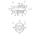
- FIG. 7A is a cross-sectional view of a rotor
- FIG. 7B is a view taken in the direction of arrow A, illustrating a reference example for explaining the first embodiment.
- It is a perspective view of the rotor which applied the modified partition and shows the modification of the partition of FIG.
- It is a top view which shows the modification of the partition of FIG.
- FIG. 1 The modification of the partition of Embodiment 1 is shown
- FIG.5 (a) is a perspective view of a rotor
- FIG. 6B is a plan view of the partition wall, showing a modification of the partition wall according to the first embodiment
- FIG. 7A is a cross-
- a magnetic inductor type electric motor (hereinafter, “motor”) 1 includes a rotor 3 fixed to a rotating shaft 2, a stator core 8 disposed so as to surround the rotor 3, and a field.
- a stator 7 having a permanent magnet 12 constituting a magnetomotive force generating portion and a coil 11 constituting a torque generating drive portion mounted thereon, and a case 13 for housing the rotor 3 and the stator 7 are provided. If the case 13 is formed of a magnetic material, the magnetic flux of the permanent magnet 12 flows through the case 13 and it becomes difficult to contribute to torque. Therefore, the case 13 is preferably formed of a non-magnetic material.
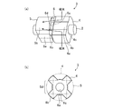
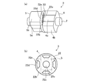
- FIG. 2A shows an enlarged perspective view of the rotor 3, and FIG. 2B shows a plan view of the partition wall 6.
- the rotor 3 includes a first magnetic body 4 and a second magnetic body 5 that are produced by laminating and integrating a plurality of magnetic steel plates formed in a predetermined shape in the axial direction of the rotary shaft 2, and a plate-like magnetic member. And a partition wall 6 in which an insertion hole 6c for inserting the rotating shaft 2 is formed.
- the first magnetic body 4 and the second magnetic body 5 are manufactured to have substantially the same shape, and are provided with insertion holes 4c and 5c (insertion holes 5c are shown in FIG. 1) for inserting the rotary shaft 2 at the axial center position.
- the first magnetic body 4 and the second magnetic body 5 are disposed in close contact with each other via the partition wall 6 with the salient poles 4b and 5b shifted by a half pitch in the circumferential direction, and inserted through the insertion holes 4c and 5c. It is configured to be fixed to the rotating shaft 2.
- the partition wall 6 includes a disc-shaped base portion 6a in which insertion holes 6c are formed, and four protrusions 6b that protrude from the outer peripheral surface of the base portion 6a in the radial direction outward at an equiangular pitch in the circumferential direction. It is configured. Moreover, four places between the protrusions 6b adjacent to each other in the circumferential direction are notches 6d.
- the outer diameter of the base portion 6 a is larger than the outer diameters of the base portion 4 a of the first magnetic body 4 and the base portion 5 a of the second magnetic body 5.
- the outer diameter of the protrusion 6 b is equal to the outer diameter of the salient pole 4 b of the first magnetic body 4 and the salient pole 5 b of the second magnetic body 5.
- the protrusion 6 b is disposed between the salient pole 4 b of the first magnetic body 4 and the salient pole 5 b of the second magnetic body 5 when viewed from the axial direction. Furthermore, the axial thickness of the partition wall 6 is shorter than the axial thickness of the permanent magnet 12.
- the stator iron core 8 includes a first stator iron core 9 and a second stator produced by laminating and integrating a plurality of magnetic steel plates formed in a predetermined shape in the axial direction of the rotary shaft 2.
- An iron core 10 is provided.
- the first stator core 9 and the second stator core 10 are manufactured to have the same shape, and are protruded radially inward from the outer peripheral surfaces of the cylindrical core backs 9a and 10a and the core backs 9a and 10a. 6 teeth 9b and 10b provided at equiangular pitches in the direction.
- the first stator core 9 and the second stator core 10 are disposed at positions that surround the first magnetic body 4 and the second magnetic body 5 with the circumferential positions of the teeth 9b and 10b being matched.
- one coil 11 is wound around the pair of teeth 9b and 10b, and ends of these coils 11 are connected to a power distribution plate (so-called bus bar) (not shown).
- a disk-shaped permanent magnet 12 is interposed between the core backs 9a and 10a, and the stator 7 and the rotor 3 are positioned so that the permanent magnet 12 and the partition wall 6 face each other.
- the magnetic flux of the permanent magnet 12 flows from the salient poles 5 b of the second magnetic body 5 to the first stator core 9, then flows in the axial direction, and flows from the second stator core 10 to the first stator core 10. Since it returns to the salient pole 4b of the magnetic body 4, the salient poles 4b and 5b are excited. At this time, since the salient poles 4b and 5b are shifted by a half pitch in the circumferential direction, the magnetic flux acts as if the N and S poles are alternately arranged in the circumferential direction when viewed from the axial direction.
- the S pole and the N pole of the teeth 9b, 10b of the stator core 8 are switched. Then, torque is generated by the interaction between the field magnetomotive force of the permanent magnet 12 and the current flowing through the coil 11, and the rotor 3 rotates in the circumferential direction.
- a field magnetomotive force may be obtained by installing a field coil instead of the permanent magnet 12.
- the case 13 is preferably formed of a magnetic material.
- the axial thickness of the partition wall 6 is made thinner than the axial thickness of the permanent magnet 12, it contributes to the torque that flows from the second stator core 10 to the first stator core 9 via the partition wall 6. Generation of magnetic flux that does not occur is suppressed. Thereby, leakage magnetic flux is reduced and a large torque can be secured.
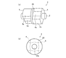
- FIG. 3A shows a perspective view of the rotor 3 using the disk-shaped partition wall 20 proposed in Patent Document 1
- FIG. 3B shows a plan view of the partition wall 20.
- the partition wall 20 has a disk-like magnetic body with an insertion hole 20 a of the rotary shaft 2, and has an outer diameter that is the same as the outer diameter of the first magnetic body 4 and the second magnetic body 5.
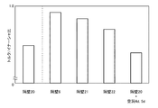
- FIG. 4 shows the result of measuring the torque / inertia ratio by changing the shape of the partition wall. The larger the torque / inertia ratio on the vertical axis of the graph, the higher the acceleration performance.
- the partition walls 21 and 22 and the partition wall 20 + cavities 4d and 5d will be described later.
- the partition wall 6 according to the first embodiment shown in FIG. 2 has four notches 6d. Can be reduced. Since the four protrusions 6b are formed at the same angular pitch and in the same shape, no shaft runout occurs when the rotor 3 is rotated at a high speed. Even if these four places are cut out, the projecting portion 6b exists between the salient poles 4b and 5b, so that the salient poles 4b and 5b are magnetically connected via the projecting portion 6b. Therefore, as indicated by an arrow in FIG.
- the magnetic flux emitted from the stator 7 side enters the salient pole 4b of the first magnetic body 4, and the projection 6b disposed between the salient pole 4b and the salient pole 5b.
- a magnetic path is formed which flows to the salient pole 5b of the second magnetic body 5 via the path and returns to the stator 7 side again.
- the protruding portion since the outer diameter of the base portion 6a is formed larger than the outer diameters of the base portions 4a and 5a, the protruding portion also functions as a magnetic path. Accordingly, the torque can be maintained without impeding the flow of magnetic flux of the rotor 3.
- the partition wall 6 can reduce the windage loss and maintain the torque in the same manner as the partition wall 20, but can reduce the inertia as compared with the partition wall 20. Therefore, as shown in FIG. 4, the torque / inertia ratio is large. , Acceleration performance is improved.
- the four protrusions 6 b are formed on the partition wall 6 according to this number. What is necessary is just to form the protrusion part 6b according to the number of the clearance gaps between the salient poles 4b and 5b.
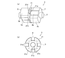
- the partition wall 21 is equiangular with the disc-shaped base portion 21a in which the insertion hole 21c of the rotating shaft 2 is formed in the circumferential direction.
- the four pitches are each composed of a protruding portion 21b protruding in a fan shape that spreads outward from the outer peripheral surface of the base portion 21a in the radial direction. Since the partition wall 21 is formed in the same manner as the partition wall 6 to reduce the weight by forming a cutout portion 21d having a shape in which four discs are cut out, the conventional disk-shaped partition wall 20 as shown in FIG.
- the torque / inertia ratio is large.
- the volume of the partition wall 21 is larger than that of the partition wall 6 by the extent that each protrusion 21b extends in a fan shape. Therefore, the effect of reducing the inertia is slightly smaller than that of the partition wall 6, and the torque / inertia ratio is also small. Small.
- the partition wall 22 is equiangular with the disc-shaped base portion 22a in which the insertion hole 22c of the rotating shaft 2 is formed in the circumferential direction.
- Each of the four pitches includes a protrusion 22b that protrudes radially outward from the outer peripheral surface of the base 22a, and a total of four connecting portions 22d that connect the radially outward of adjacent protrusions 22b. ing. Since the partition wall 22 is lightened by forming four holes 22e in the disk, as shown in FIG. 4, the effect of reducing the inertia is larger than that of the conventional disk-shaped partition wall 20, and the torque is reduced. / Inertia ratio is large.
- the volume of the partition wall 22 is larger than that of the partition wall 6 as much as the connecting portions 22d are formed, and the connecting portion 22d is positioned at the outer edge of the partition wall 22.
- the torque / inertia ratio is small.
- FIG. 7 shows a configuration for reducing the weight of the first magnetic body 4 and the second magnetic body 5 instead of the partition walls 6, 21, and 22.
- the cavity 4d is formed in each of the two salient poles 4b of the first magnetic body 4, and the second magnetic body 5 is formed.
- two cavities 5d are formed. Further, between the first magnetic body 4 and the second magnetic body 5, the same disc-shaped partition wall 20 as that in FIG. 3 is interposed.
- the rotor 3 has a hollow structure for the first magnetic body 4 and the second magnetic body 5 so as to reduce the weight, so that there is an effect of reducing the inertia, but the flow of magnetic flux is obstructed by the cavities 4d and 5d, and the torque is reduced. As a result, the torque / inertia ratio becomes small as shown in FIG. For this reason, it is preferable to reduce the inertia by reducing the weight of the partition wall 6 instead of the first magnetic body 4 and the second magnetic body 5.
- the electric motor 1 is configured such that the salient poles 4b protrude from the outer periphery of the cylindrical base portion 4a having the insertion hole 4c at the axial center position at an equiangular pitch in the circumferential direction.
- the permanent magnet 12 that excites the salient poles 4b and 5b of the rotor 3 and the rotor 3 generate rotational torque.
- the partition wall 6 is sandwiched between the salient poles 4b of the first magnetic body 4 and the salient poles 5b of the second magnetic body 5 which are disposed at positions shifted in the axial direction. In addition to the region, the notch 6d was formed.
- the partition walls 21 and 22 also have notches other than the portion sandwiched between the salient poles 4b of the first magnetic body 4 and the salient poles 5b of the second magnetic body 5 arranged at positions shifted in the axial direction. It was set as the structure in which the part 21d or the hole 22e was formed.
- the volume can be reduced and the inertia can be reduced.
- the partition walls 6, 21, and 22 exist in the gap between the salient poles 4 b and 5 b, the axial direction flowing from the first magnetic body 4 to the second magnetic body 5 through the gap between the salient poles 4 b and 5 b Airflow can be blocked and windage loss can be reduced. Therefore, the electric motor 1 with reduced inertia can be provided without impairing the windage loss reducing effect of the partition walls 6, 21, 22.
- the partition walls 6 and 21 have the disc-like base portions 6a and 21a having the insertion holes 6c and 21c at the axial center positions, and the equiangular pitch in the circumferential direction on the outer periphery of the base portions 6a and 21a.
- a magnetic member having a shape in which the protrusions 6b and 21b are formed in a projecting manner, and the protrusions 6b and 21b are notched between the protrusions 6b or 21b.
- the salient poles 4b of the first magnetic body 4 and the salient poles 5b of the second magnetic body 5 arranged at the above positions are arranged such that these salient poles 4b and 5b are magnetically connected. For this reason, an inertia can be reduced, without inhibiting the magnetic flux which flows through the rotor 3.
- the four protrusions 6b of the partition wall 6 are configured in the same shape.
- the partition wall 21 has four protrusions 21b having the same shape. For this reason, the shaft shake at the time of rotation can be prevented, and the electric motor 1 suitable for use where high speed rotation is required can be provided.
- the outer diameter of the base portion 6 a of the partition wall 6 is configured to be larger than the outer diameters of the base portions 4 a and 5 a of the first magnetic body 4 and the second magnetic body 5.
- the partition walls 21 and 22 are also configured such that the outer diameters of the base portions 21 a and 22 a are larger than the outer diameters of the base portions 4 a and 5 a of the first magnetic body 4 and the second magnetic body 5. For this reason, a magnetic path comes to be formed in base 6a, 21a, 22a, and an inertia can be reduced, without inhibiting the magnetic flux which flows through the rotor 3.
- the axial thickness of the partition wall 6 is made thinner than the axial thickness of the permanent magnet 12.
- the partition walls 21 and 22 are also configured such that the axial thickness is thinner than the axial thickness of the permanent magnet 12. For this reason, the leakage magnetic flux which does not contribute to a torque can be reduced.
- any component of the embodiment can be modified or any component of the embodiment can be omitted within the scope of the invention.
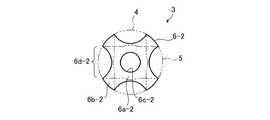
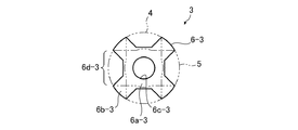
- FIG. 8 to 10 show modified examples of the partition wall 6.
- FIG. 8 to 10 the same or corresponding parts as those in FIG. 2 are denoted by the same reference numerals and the description thereof is omitted.
- both ends of each of the four protrusions 6b-1 are cut off obliquely with respect to the axial direction to secure a minimum magnetic path.
- the notch 6d-1 may be enlarged to reduce the weight and further reduce the inertia.
- the connecting portion of the base portion 6a-2 and the protruding portion 6b-2 has a curved shape, and this connecting portion stresses when the rotor 3 rotates at high speed.
- the outer peripheral surface of the base 6a-3 may be a flat shape instead of a curved surface.
- the above modifications can also be applied to the partition walls 21 and 22.
- the electric motor according to the present invention enables inertia reduction without impairing the windage loss reduction effect, and therefore, a magnetic inductor type synchronous motor that rotationally drives a turbine such as an electric compressor and an electric assist turbo at high speed, etc. Suitable for use in.
Landscapes
- Engineering & Computer Science (AREA)
- Power Engineering (AREA)
- Iron Core Of Rotating Electric Machines (AREA)
- Synchronous Machinery (AREA)
- Permanent Field Magnets Of Synchronous Machinery (AREA)
Abstract
Priority Applications (4)
| Application Number | Priority Date | Filing Date | Title |
|---|---|---|---|
| JP2014509904A JP5557971B2 (ja) | 2012-04-10 | 2012-04-10 | 電動機 |
| DE112012006225.6T DE112012006225T5 (de) | 2012-04-10 | 2012-04-10 | Elektromotor |
| PCT/JP2012/002486 WO2013153575A1 (fr) | 2012-04-10 | 2012-04-10 | Moteur électrique |
| US14/373,379 US20140354101A1 (en) | 2012-04-10 | 2012-04-10 | Electric motor |
Applications Claiming Priority (1)
| Application Number | Priority Date | Filing Date | Title |
|---|---|---|---|
| PCT/JP2012/002486 WO2013153575A1 (fr) | 2012-04-10 | 2012-04-10 | Moteur électrique |
Publications (1)
| Publication Number | Publication Date |
|---|---|
| WO2013153575A1 true WO2013153575A1 (fr) | 2013-10-17 |
Family
ID=49327191
Family Applications (1)
| Application Number | Title | Priority Date | Filing Date |
|---|---|---|---|
| PCT/JP2012/002486 Ceased WO2013153575A1 (fr) | 2012-04-10 | 2012-04-10 | Moteur électrique |
Country Status (4)
| Country | Link |
|---|---|
| US (1) | US20140354101A1 (fr) |
| JP (1) | JP5557971B2 (fr) |
| DE (1) | DE112012006225T5 (fr) |
| WO (1) | WO2013153575A1 (fr) |
Cited By (4)
| Publication number | Priority date | Publication date | Assignee | Title |
|---|---|---|---|---|
| WO2015098159A1 (fr) * | 2013-12-25 | 2015-07-02 | 三菱電機株式会社 | Moteur d'induction magnétique et son procédé de fabrication |
| WO2016045663A1 (fr) * | 2014-09-22 | 2016-03-31 | Technische Universität Berlin | Transformateur électrodynamique |
| EP3069432A4 (fr) * | 2013-11-13 | 2017-11-29 | Brooks Automation, Inc. | Moteur à réluctance commutée étanche |
| US10348172B2 (en) | 2013-11-13 | 2019-07-09 | Brooks Automation, Inc. | Sealed switched reluctance motor |
Families Citing this family (2)
| Publication number | Priority date | Publication date | Assignee | Title |
|---|---|---|---|---|
| CN109412370A (zh) * | 2019-01-02 | 2019-03-01 | 安徽理工大学 | 磁通切换式直线旋转永磁作动器 |
| CN110855034B (zh) * | 2019-11-20 | 2020-12-01 | 湖南大学 | 一种机械调磁永磁同性极式感应子电机 |
Citations (3)
| Publication number | Priority date | Publication date | Assignee | Title |
|---|---|---|---|---|
| JPH08214519A (ja) * | 1995-02-06 | 1996-08-20 | Akira Chiba | 永久磁石を用いた両突極性電動発電機 |
| JP2009005572A (ja) * | 2007-05-24 | 2009-01-08 | Mitsubishi Electric Corp | 磁気誘導子形同期回転機およびそれを用いた自動車用過給機 |
| WO2009136574A1 (fr) * | 2008-05-08 | 2009-11-12 | 三菱電機株式会社 | Moteur électrique rotatif et ventilateur l'utilisant |
Family Cites Families (10)
| Publication number | Priority date | Publication date | Assignee | Title |
|---|---|---|---|---|
| US3293459A (en) * | 1964-04-30 | 1966-12-20 | Robertshaw Controls Co | Stepping motors and control means |
| US4385251A (en) * | 1981-09-28 | 1983-05-24 | General Electric Company | Flux shield for an inductor-alternator machine |
| SE431275B (sv) * | 1983-04-07 | 1984-01-23 | Vnii Elektromash | Elektrisk maskin |
| JPS61176977U (fr) * | 1985-04-24 | 1986-11-05 | ||
| US4639626A (en) * | 1985-04-26 | 1987-01-27 | Magnetics Research International Corporation | Permanent magnet variable reluctance generator |
| JPH06351206A (ja) * | 1993-04-14 | 1994-12-22 | Meidensha Corp | ハイブリッド励磁形永久磁石同期回転機 |
| DE102006012215A1 (de) * | 2006-03-16 | 2007-09-20 | Mtu Aero Engines Gmbh | Transversalflussmaschine und Turbomaschine mit derartiger Transversalflussmaschie |
| JP4623472B2 (ja) * | 2007-01-30 | 2011-02-02 | トヨタ自動車株式会社 | 回転電動機 |
| JP2008228442A (ja) * | 2007-03-13 | 2008-09-25 | Hitachi Ltd | ステッピングモータ及びステッピングモータを製造する鋼板 |
| JP5388919B2 (ja) * | 2010-03-23 | 2014-01-15 | 三菱電機株式会社 | 高速回転電動機およびそれに用いられる回転子 |
-
2012
- 2012-04-10 WO PCT/JP2012/002486 patent/WO2013153575A1/fr not_active Ceased
- 2012-04-10 JP JP2014509904A patent/JP5557971B2/ja not_active Expired - Fee Related
- 2012-04-10 US US14/373,379 patent/US20140354101A1/en not_active Abandoned
- 2012-04-10 DE DE112012006225.6T patent/DE112012006225T5/de not_active Withdrawn
Patent Citations (3)
| Publication number | Priority date | Publication date | Assignee | Title |
|---|---|---|---|---|
| JPH08214519A (ja) * | 1995-02-06 | 1996-08-20 | Akira Chiba | 永久磁石を用いた両突極性電動発電機 |
| JP2009005572A (ja) * | 2007-05-24 | 2009-01-08 | Mitsubishi Electric Corp | 磁気誘導子形同期回転機およびそれを用いた自動車用過給機 |
| WO2009136574A1 (fr) * | 2008-05-08 | 2009-11-12 | 三菱電機株式会社 | Moteur électrique rotatif et ventilateur l'utilisant |
Cited By (13)
| Publication number | Priority date | Publication date | Assignee | Title |
|---|---|---|---|---|
| EP3069432A4 (fr) * | 2013-11-13 | 2017-11-29 | Brooks Automation, Inc. | Moteur à réluctance commutée étanche |
| US11444521B2 (en) | 2013-11-13 | 2022-09-13 | Brooks Automation Us, Llc | Sealed switched reluctance motor |
| US10348172B2 (en) | 2013-11-13 | 2019-07-09 | Brooks Automation, Inc. | Sealed switched reluctance motor |
| JP6026021B2 (ja) * | 2013-12-25 | 2016-11-16 | 三菱電機株式会社 | 磁気誘導子型電動機およびその製造方法 |
| WO2015098159A1 (fr) * | 2013-12-25 | 2015-07-02 | 三菱電機株式会社 | Moteur d'induction magnétique et son procédé de fabrication |
| US9966824B2 (en) | 2013-12-25 | 2018-05-08 | Mitsubishi Electric Corporation | Magnetic inductor electric motor and manufacturing method therefor |
| CN105723596B (zh) * | 2013-12-25 | 2018-08-03 | 三菱电机株式会社 | 磁感应式电动机及其制造方法 |
| DE112014006070B4 (de) | 2013-12-25 | 2018-09-20 | Mitsubishi Electric Corporation | Elektromotor mit magnetischem Induktor und zugehöriges Herstellungsverfahren |
| CN105723596A (zh) * | 2013-12-25 | 2016-06-29 | 三菱电机株式会社 | 磁感应式电动机及其制造方法 |
| CN107112871A (zh) * | 2014-09-22 | 2017-08-29 | 柏林工业大学 | 电动力的变换器 |
| CN107112871B (zh) * | 2014-09-22 | 2019-12-13 | 柏林工业大学 | 电动力的变换器 |
| US10756608B2 (en) | 2014-09-22 | 2020-08-25 | Technische Universitat Berlin | Electrodynamic converter |
| WO2016045663A1 (fr) * | 2014-09-22 | 2016-03-31 | Technische Universität Berlin | Transformateur électrodynamique |
Also Published As
| Publication number | Publication date |
|---|---|
| US20140354101A1 (en) | 2014-12-04 |
| JP5557971B2 (ja) | 2014-07-23 |
| DE112012006225T5 (de) | 2015-01-15 |
| JPWO2013153575A1 (ja) | 2015-12-17 |
Similar Documents
| Publication | Publication Date | Title |
|---|---|---|
| JP5643127B2 (ja) | 回転電機用回転子 | |
| JP4692090B2 (ja) | アキシャルエアギャップ型電動機 | |
| JP4999990B2 (ja) | 回転電動機およびそれを用いた送風機 | |
| JP5557971B2 (ja) | 電動機 | |
| CN100578892C (zh) | 电动发电机 | |
| JP5159228B2 (ja) | 磁気誘導子形同期回転機およびそれを用いた自動車用過給機 | |
| JP5609689B2 (ja) | 回転電機 | |
| JP6460159B2 (ja) | ロータ及びモータ | |
| JP5918967B2 (ja) | ロータ、モータ及びロータの製造方法 | |
| JP2010098929A (ja) | ダブルギャップモータ | |
| JP5347588B2 (ja) | 埋め込み磁石式モータ | |
| WO2020017078A1 (fr) | Machine électrique rotative | |
| JP2011078283A (ja) | 永久磁石埋込型モータの回転子及び送風機及び圧縮機 | |
| JPWO2014030251A1 (ja) | 回転電動機および内燃機関用過給機 | |
| JP5439904B2 (ja) | 回転電機 | |
| JP2015047009A (ja) | 回転電機 | |
| CN103259354B (zh) | 转子和马达 | |
| JP5947230B2 (ja) | モータ | |
| JP5944683B2 (ja) | ロータ及びモータ | |
| JP2013005627A (ja) | ロータ及びモータ | |
| JP2013021844A (ja) | 回転電機 | |
| KR20180138323A (ko) | 자속 집중형 모터 | |
| JP5855903B2 (ja) | ロータ及びモータ | |
| JP2013169073A (ja) | ロータ及びモータ | |
| JP2013201865A (ja) | ブラシレスモータ |
Legal Events
| Date | Code | Title | Description |
|---|---|---|---|
| 121 | Ep: the epo has been informed by wipo that ep was designated in this application |
Ref document number: 12874171 Country of ref document: EP Kind code of ref document: A1 |
|
| ENP | Entry into the national phase |
Ref document number: 2014509904 Country of ref document: JP Kind code of ref document: A |
|
| WWE | Wipo information: entry into national phase |
Ref document number: 14373379 Country of ref document: US |
|
| WWE | Wipo information: entry into national phase |
Ref document number: 112012006225 Country of ref document: DE Ref document number: 1120120062256 Country of ref document: DE |
|
| 122 | Ep: pct application non-entry in european phase |
Ref document number: 12874171 Country of ref document: EP Kind code of ref document: A1 |