WO2013153639A1 - Dispositif pour retenir une porte en position ouverte et dispositif de charnière de porte équipé de celui-ci - Google Patents
Dispositif pour retenir une porte en position ouverte et dispositif de charnière de porte équipé de celui-ci Download PDFInfo
- Publication number
- WO2013153639A1 WO2013153639A1 PCT/JP2012/059930 JP2012059930W WO2013153639A1 WO 2013153639 A1 WO2013153639 A1 WO 2013153639A1 JP 2012059930 W JP2012059930 W JP 2012059930W WO 2013153639 A1 WO2013153639 A1 WO 2013153639A1
- Authority
- WO
- WIPO (PCT)
- Prior art keywords
- door
- axis
- engagement member
- engagement
- spring
- Prior art date
- Legal status (The legal status is an assumption and is not a legal conclusion. Google has not performed a legal analysis and makes no representation as to the accuracy of the status listed.)
- Ceased
Links
Images



Classifications
-
- E—FIXED CONSTRUCTIONS
- E05—LOCKS; KEYS; WINDOW OR DOOR FITTINGS; SAFES
- E05D—HINGES OR SUSPENSION DEVICES FOR DOORS, WINDOWS OR WINGS
- E05D11/00—Additional features or accessories of hinges
- E05D11/10—Devices for preventing movement between relatively-movable hinge parts
- E05D11/1014—Devices for preventing movement between relatively-movable hinge parts for maintaining the hinge in only one position, e.g. closed
-
- E—FIXED CONSTRUCTIONS
- E05—LOCKS; KEYS; WINDOW OR DOOR FITTINGS; SAFES
- E05F—DEVICES FOR MOVING WINGS INTO OPEN OR CLOSED POSITION; CHECKS FOR WINGS; WING FITTINGS NOT OTHERWISE PROVIDED FOR, CONCERNED WITH THE FUNCTIONING OF THE WING
- E05F3/00—Closers or openers with braking devices, e.g. checks; Construction of pneumatic or liquid braking devices
- E05F3/22—Additional arrangements for closers, e.g. for holding the wing in opened or other position
- E05F3/221—Mechanical power-locks, e.g. for holding the wing open or for free-moving zones
-
- E—FIXED CONSTRUCTIONS
- E05—LOCKS; KEYS; WINDOW OR DOOR FITTINGS; SAFES
- E05Y—INDEXING SCHEME ASSOCIATED WITH SUBCLASSES E05D AND E05F, RELATING TO CONSTRUCTION ELEMENTS, ELECTRIC CONTROL, POWER SUPPLY, POWER SIGNAL OR TRANSMISSION, USER INTERFACES, MOUNTING OR COUPLING, DETAILS, ACCESSORIES, AUXILIARY OPERATIONS NOT OTHERWISE PROVIDED FOR, APPLICATION THEREOF
- E05Y2900/00—Application of doors, windows, wings or fittings thereof
- E05Y2900/10—Application of doors, windows, wings or fittings thereof for buildings or parts thereof
- E05Y2900/13—Type of wing
- E05Y2900/132—Doors
Definitions
- the present invention relates to a door hinge device, and more particularly to a door hinge device having a function of holding a door in an open state.
- a door hinge device of a type in which a pair of pivots aligned in the vertical direction are provided at the upper and lower portions of the door, and the pair of pivots are pivotally attached to pivot receiving devices provided on the upper and lower door frames the door hinge device is set to the open position.
- a door hinge device provided with a door-opening holding device that holds the door in its open position for example, Patent Document 1.
- the second pivot shaft fixed to the door is concentrically fitted with the first pivot shaft fixed to one of the upper and lower door frames so as to be relatively rotatable.
- An engagement protrusion is provided on the cylindrical outer peripheral surface of the first pivot shaft on the door frame side, and a roller-shaped engagement member pressed against the outer peripheral surface of the first pivot shaft by a spring force on the door side.
- the engaging member rolls on the outer peripheral surface of the first pivot shaft as the door opens and closes. When the door reaches the door opening position, the engaging member I try to get over.
- the engaging member that moves together with the door is locked by the engaging projection, and thereby the door closing movement is stopped and held in the open position. Is done.
- the position of the engagement protrusion on the outer peripheral surface of the first pivot shaft can be adjusted by adjusting the first pivot shaft to a desired angular position around its central axis, thereby holding the door
- the opening position to be adjusted can be adjusted.
- the engagement member provided on the door side gets over the engagement protrusion provided on the door frame side against the spring force.
- the same force is required when the door is set to the open position.
- the spring force In order to securely hold the door in the open position, the spring force must be greater than a certain value. Therefore, as can be seen from the above, a large force is applied when the door is finally set to the open position. May be an obstacle to smooth opening of doors.
- An object of the present invention is to provide a device and a door hinge device including the device.
- the present invention A pivot shaft having a first axis fixed to one of the door and the door frame; A pivot receiving device attached to the other of the door and the door frame, the pivot receiving device having a pivot hole for receiving the pivot shaft, wherein the pivot shaft is centered on the first axis as the door is opened and closed.
- a pivot receiving device capable of rotating relative to the door hinge device, the door opening holding device for holding the door in the opening position at the opening position, A first engagement member attached to the pivot shaft and performing relative rotation about the first axis with respect to the pivot hole together with the pivot shaft as the door opens and closes.
- a first engagement member having an engagement protrusion protruding radially outward as a reference;
- the first projection is pivotally mounted around a second axis parallel to the first axis outside the arcuate movement path of the mating projection, and is spring-biased so as to be positioned on the movement path of the engagement projection. 2 engaging members, and when the door is opened and approaches the door opening position, the engaging projection is relatively slidably engaged with the second engaging member to the spring biasing force.
- the second engagement member is pivoted out of the movement path to allow the first engagement member to advance, and when the door reaches the door opening position, the spring biasing force causes the second engagement member to advance.
- the door When the door is to be closed from the opening position, it engages with the engaging protrusion and moves the second position. Stopping the relative rotation of the engagement member, thereby a second engaging member that holds the door in the open door position,
- the second engagement member includes a sliding engagement surface that is slidably engaged by the engagement protrusion when the door approaches the door opening position, and when the door attempts to close from the door opening position.
- a locking surface that engages with the engaging protrusion and stops the movement of the first engaging member, and the sliding engaging surface attaches the second engaging member to the spring by the engaging protrusion.
- a first force that pivots against a force is received, and the locking surface receives a second force that pivots the second engagement member against the spring force, and the second force
- An opening retention device is provided, wherein the action line is shaped to pass closer to the second axis than the action line of the first force.
- the second engagement member tries to pivot against the spring biasing force received by the second engagement member when the door is about to close from the door opening position.
- the action line of the second force is greater than the action line of the first force that attempts to pivot the second engagement member against the spring biasing force received by the second engagement member when the door is opened. Since it is designed to pass near the two axes, the second force required when closing the door must be greater than the first force required when opening the door. Although it can be performed with a small force, a large force acts against the door to be closed from the open position, and the door can be reliably held at the open position.
- the sliding engagement of the second engaging member is engaged with the second engaging member when not engaged by the engaging protrusion so as to resist the spring biasing force.
- a stopper can be provided so that the mating surface and the locking surface are positioned on the movement path.
- the spring biasing force can be set by pressing the second engagement member against the stopper in a state where the second engagement member is engaged with the stopper, and the spring is adjusted by adjusting the pressing force. The biasing force can be adjusted.
- the second engagement member is displaceable in a state in which the second engagement member is engaged with the stopper, and the engagement projection is engaged with the locking surface of the second engagement member.
- the pivot position of the pivot shaft can be adjusted. By doing in this way, it becomes possible to adjust the door opening holding angle of a door.
- the angle can be adjusted around the third axis parallel to the first and second axes at a position farther from the first axis than the second axis, and attached to the fixing substrate.
- the second engaging member is pivotable about the second axis positioned between the first axis and the third axis. It can be pivoted. The position of the second engagement member can be adjusted by adjusting the angle of the engagement member holder around the third axis.
- the door holding device further includes a spring storage cylinder portion fixed to the fixed substrate in parallel with the engagement member holder, and the spring is stored as a coil spring in the spring storage cylinder portion, and the engagement
- the member holder has a first screw hole penetrating a position closer to the pivot axis than the third axis from a side adjacent to the spring storage cylinder part to a side away from the spring storage cylinder part, and more than the third axis.
- the spring housing cylinder portion has a side surface adjacent to the engaging member holder, and the side surface has an inclined surface inclined in a direction away from the engaging member holder with respect to a surface parallel to the engaging member holder. Then, the engagement member holder can be turned around the third axis.
- the engagement member holder in order to rotate the engagement member holder without interference by the spring storage tube portion, the engagement member holder must be largely separated from the spring storage tube portion.
- the holding device has to be enlarged, by providing the inclined surface, the engaging member holder can be provided close to the spring housing cylinder.
- the door opening holding device is The pivot receiving device is fixed to the other of the door and the door frame; A door holding main body fixed to the fixing substrate; Have The main body for holding the door has the spring accommodating cylinder, An engagement member holder is pivotally attached about the third axis to the door retaining body; The first engagement member may be pivotally attached to the door holding main body about the first axis.
- the first engaging member is pivotally attached to the pivot receiving device, is aligned with the pivot shaft along the first axis, and is coupled so as not to rotate relative to the pivot shaft. Can be.
- the first engagement member has a small-diameter portion extending along the axis of the first engagement member, the pivot shaft is cylindrical, and the small-diameter portion is coaxial within the pivot shaft. Can be inserted and connected.
- the present invention also provides a door hinge device including the door opening holding device as described above.
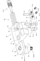
- FIG. 1 It is a side view which shows embodiment of the door hinge apparatus provided with the open door holding
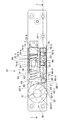
- FIG. 1 It is a figure which shows a motion of the component when the door hinge apparatus of FIG. 1 moves between a closed position and an open position, (a) when a door exists in a closed position, (b) is about 45 degree
- the door hinge device 10 pivots the pivot shaft device 12 attached to the upper edge D1 of the door D and the pivot shaft 14 of the pivot shaft device 12 attached to the door frame F. And a pivot receiving device 16 for receiving it.
- the pivot shaft device 12 includes a fixed base plate 18 fixed to the upper edge of the door D, a support cylinder 20 fixed to the fixed base plate 18 and capable of moving the pivot shaft 14 so as to move up and down, and the pivot shaft 14 supported. And an arm device 22 that moves up and down in the cylinder 20.
- the pivot shaft 14 is pulled into the support cylinder 20 before the door D is attached to the door frame F.
- the arm 22-1 is rotated in the direction of arrow A to pivot.
- the shaft 14 protrudes upward in the direction of the arrow B and is inserted into the pivot hole 24 in the pivot receiving device 16 so as to be held at that position.
- Japanese Utility Model Publication No. 6-10066 it is widely known in Japanese Utility Model Publication No. 6-10066. Therefore, detailed description thereof is omitted here.
- the pivot receiving device 16 includes a fixing substrate 26 fixed to the door frame F by screws 28, and a pivot cylinder portion that is press-fitted and fixed in a hole of the fixing substrate 26 to define the pivot hole 24. 30, and a pivot shaft 14 extending from the pivot shaft device 12 is rotatably accommodated in a pivot hole 24.
- a pivot shaft device and a pivot receiving device similar to the above are arranged on an axis (first axis in the claims) X1 extending in the vertical direction to the lower edge portion and the lower door frame portion of the door D. And the door D is pivoted about the axis X1.
- the pivot receiving device 16 includes the door opening holding device 32 for holding the door D at the door opening position when the door D is set to the door opening position at a predetermined angular position.
- the door-opening holding device 32 includes a block-shaped door-holding main body 34 that is fixed to the fixing substrate 26 with screws 33.
- the main body 34 for holding the door has a bearing portion 36 that extends substantially horizontally at a position spaced upward from the pivot cylinder portion 30, and the bearing portion 36 extends in the direction of the pivot cylinder portion 30 and the first axis X 1. Aligned bearing holes 38 are provided.
- a large-diameter portion 44 of the rotation shaft 42 of the first engagement member 40 is attached to the bearing hole 38 so as to be rotatable about the axis X1.
- the first engaging member 40 receives a connecting portion 47 of the rotating shaft 42 and is connected so as not to rotate with respect to the rotating shaft 42 and a cylindrical portion extending downward from the peripheral portion of the connecting portion 46. 48, and the tubular portion 48 is fitted around the upper end outer peripheral portion of the support tube 20 so as to be relatively rotatable.
- the rotating shaft 42 has a small-diameter portion 50 that extends downward along the first axis X1.
- a serration 52 that extends along the first axis X1 direction is formed on the outer peripheral surface thereof, and a corresponding serration 54 is formed.
- the cylindrical pivot shaft 14 is inserted into the inner hole 14-1 so as to rotate together with the pivot shaft 14.
- a small-diameter roller 62 is embedded in the cylindrical outer peripheral surface 40-1 of the first engaging member 40 in parallel with the first axis X1, and a part of the roller 62 protrudes from the cylindrical outer peripheral surface 40-1.
- An engagement protrusion 62-1 of one engagement member 40 is formed.
- the door opening holding device 32 is pivotable around a second axis X2 parallel to the first axis X1 outside the arcuate movement path of the engagement protrusion 62-1 when the first engagement member 40 rotates.
- the second engagement member 66 is attached, and the second engagement member 66 is urged to be positioned on the moving path 62-2 of the engagement protrusion 62-1 by the coil spring 64 (FIG. 3). .
- the second engagement member 66 is configured so that the door D (and hence the pivot shaft device 12 fixed to the door) is moved from the door closing position shown in FIG. 4A to the door opening position shown in FIG. (C) in FIG.
- the engaging protrusion 62-1 is slidably engaged with the second engaging member 66 and resists the urging force of the coil spring 64, thereby engaging the second engaging member 66. Is allowed to move out of the moving path and when the door D reaches the door opening position ((d) in FIG. 4), it is positioned on the moving path by the urging force of the coil spring 64. When the door D is about to close from the opening position ((d) in FIG. 4), it engages with the engaging protrusion 62-1, and stops the movement of the engaging protrusion 62-1, thereby opening the door D. It is held at the door position ((d) in FIG. 4).
- the second engagement member 66 includes a sliding engagement surface 66-1 that is slidably engaged by the engagement protrusion 62-1 when the door D approaches the door opening position (FIG. 4D), A locking portion 66-3 including a locking surface 66-2 that engages with the engagement protrusion 62-1 and stops the movement of the engagement protrusion 62-1 when the door D is to be closed from the open position; A spring receiving portion 66-4 extending from the locking portion 66-3 is provided.
- the sliding engagement surface 66-1 receives a first force F1 (FIG. 4C) that pivots the second engagement member 66 against the urging force of the coil spring 64 by the engagement protrusion 62-1.
- the locking surface 66-2 receives the second force F2 that pivots the second engagement member 66 against the spring force.
- the action line of the second force F2 passes closer to the second axis X2 than the action line of the first force F1. Accordingly, the first force F1 at the time of opening the door required for the engaging protrusion 62-1 to push the second engaging member 66 against the biasing force of the coil spring 64 is the biasing force of the coil spring 64 when the door is closed. This is smaller than the second force F2 required to push the second engagement member 66 against the force. For this reason, the door can be opened with a small force, and the opened door D is held in a state opened with a large force.
- the second engagement member 66 is pivoted to the door opening holding body 34 by a shaft 68 extending along a third axis X3 that is parallel to the second axis X2 in the door opening holding body 34.
- the end of the engaging member holder 70 supported so as to be adjacent to the first engaging member 40 is pivotally supported by a shaft 72 extending around the second axis X2.
- the coil spring 64 is housed in a spring housing cylinder portion 74 formed by providing a spring housing hole 69 in the door-holding holding body 34, and extends from the end opening 74-1 of the spring housing tube portion 74.
- the stopper 60 can be engaged.
- the stopper 60 engages with the second engagement member 66 that is spring-biased by the coil spring 64, so that the sliding engagement surface 66-1 and the engagement surface 66-2 of the second engagement member 66 are In the vicinity of the outer peripheral surface 40-1 of the first engagement part 40, the first engagement member 40 is positioned in the movement path 62-2 of the engagement protrusion 62-1 of the first engagement member 40.
- a spring force adjusting member 74-3 engaged with a screw is provided in the other end opening 74-2 of the spring storing cylinder portion 74, and the spring storing member 74-3 is rotated by rotating the spring force adjusting member 74-3.
- the spring force of the coil spring 64 with respect to the second engagement member 66 can be adjusted by adjusting the degree of compression of the coil spring 64 that is inserted into and removed from the cylindrical portion 74 and sandwiched between the stopper 60.
- the engaging member holder 70 has a first screw hole 70 penetrating from the side 70-1 adjacent to the spring housing tube portion 74 away from the spring housing tube portion 74 closer to the first axis X1 than the third axis X3. -3 and a second screw penetrating from the side 70-1 adjacent to the spring accommodating cylinder 74 to the side 70-2 away from the spring accommodating cylinder 74 at a position farther from the first axis X1 than the third axis X3.
- a first adjusting screw 70-5 that is screwed into the hole 70-4, the first screw hole 70-3, and the tip engages with the spring accommodating cylinder 74, and a tip that is screwed into the second screw hole 70-4.
- the engagement member holder 70 is adjusted to a required angle with respect to the third axis X3 by adjusting the screwing position (axial position). Thereby making it possible to location.
- a side surface 74-4 parallel to the side surface of the engagement member holder 70 shown in FIG. An inclined surface 74-6 inclined from the end (the left end in FIG. 3) 74-5 of the parallel side surface 74-4 whose vertical line passes through the third axis X3 with respect to the parallel side surface 74-4.
- the engaging member holder 70 is rotatable about the third axis from the position shown in FIG. 3 to a position where the engaging member holder 70 contacts the inclined surface 74-6.
- the engaging member holder 70 can be adjusted to a required angle with respect to the third axis X3 by the second adjusting screws 70-5 and 70-6.
- FIG. 4 shows a state in which the engagement member holder 70 is tilted by adjusting such an angular position
- FIG. 5 shows a state in which the engagement member holder 70 is substantially balanced with the spring housing cylinder portion 74.
- the door hinge device includes a device for holding the door in the open position, and can be seen from a comparison between FIGS. 4C and 4D.
- the line of action of the second force F2 related to the second engagement member 66 that attempts to prevent the closing when the opened door attempts to close the door tries to prevent the opening when the door is opened. Since the second engagement member 66 passes closer to the second axis X2 that is the rotation center axis of the second engagement member 66 than the line of action of the first force F1 related to the second engagement member 66, the second force when the door is closed.
- the force F2 needs to be larger than the first force F1 when the door is opened. That is, the door can be opened with a small force, and the opened door is held at the door opening position with a large force.
- the pivot shaft device is attached to the door frame
- the pivot receiving device is attached to the door
- the door hinge according to the present invention Can be provided on the lower edge of the door and on the lower door frame.
- Door D upper edge D1; door frame F; first axis X1; second axis X2; third axis X3; first force F1; second force F2; door hinge device 10; 14; inner hole 14-1; pivot receiving device 16; fixed substrate 18; support tube 20; arm device 22; pivot hole 24; screw 28; fixing substrate 26; pivot tube portion 30; Main body 34 for holding; bearing portion 36; first engaging member 40; cylindrical outer peripheral surface; 40-1 rotating shaft 42; large diameter portion 44; connecting portions 46 and 47; Serration 54; engagement projection 62-1; coil spring 64; path 62-2; second engagement member 66; sliding engagement surface 66-1; locking surface 66-2; 68; spring accommodating hole 69; engaging member holder 70; Contact side 70-1; Side 70-2 remote from the spring housing cylinder portion; First screw hole 70-3; Second screw hole 70-4; First adjustment screw 70-5; Second adjustment screw 70-6; Shaft 72; spring accommodating cylinder 74; end opening 74-1; end opening 74-2; spring force adjusting member 74-3; parallel side surface surface
Landscapes
- Engineering & Computer Science (AREA)
- Mechanical Engineering (AREA)
- Hinges (AREA)
- Closing And Opening Devices For Wings, And Checks For Wings (AREA)
Abstract
L'invention concerne un dispositif (32) pour retenir une porte en position ouverte, qui comporte : un premier élément de prise (40), qui pivote à l'intérieur d'un trou pivot (24) autour d'un premier axe (X1) en même temps qu'une tige articulée (14), à mesure que la porte est ouverte et fermée ; et un second élément de prise (66), qui peut pivoter autour d'un second axe (X2), parallèle au premier axe. Quand la porte approche d'une position ouverte (FIG. 4d), un élément saillant de prise (62-1) glisse sur le second élément de prise (66) et entre en prise avec celui-ci, et fait pivoter et repousse cet élément vers l'extérieur d'une trajectoire de déplacement contre la force de pression d'un ressort. Si l'on essaie de fermer la porte à partir de la position ouverte, le second élément de prise (66) entre en prise avec l'élément saillant de prise (62-1) de manière à arrêter le pivotement de celui-ci, et à retenir la porte en position ouverte. La ligne d'action d'une deuxième force (F2), au moyen de laquelle l'élément saillant de prise fait pivoter le second élément de prise contre la force de pression du ressort lorsqu'on ferme la porte, est réglée de manière à se déployer suivant une trajectoire plus proche du second axe (X2) que la ligne d'action d'une première force (F1), au moyen de laquelle l'élément saillant de prise fait pivoter le second élément de prise contre la force de pression du ressort lorsqu'on ouvre la porte.
Priority Applications (2)
| Application Number | Priority Date | Filing Date | Title |
|---|---|---|---|
| JP2014509972A JP5886942B2 (ja) | 2012-04-11 | 2012-04-11 | 開扉保持装置及びそれを備えたドアヒンジ装置 |
| PCT/JP2012/059930 WO2013153639A1 (fr) | 2012-04-11 | 2012-04-11 | Dispositif pour retenir une porte en position ouverte et dispositif de charnière de porte équipé de celui-ci |
Applications Claiming Priority (1)
| Application Number | Priority Date | Filing Date | Title |
|---|---|---|---|
| PCT/JP2012/059930 WO2013153639A1 (fr) | 2012-04-11 | 2012-04-11 | Dispositif pour retenir une porte en position ouverte et dispositif de charnière de porte équipé de celui-ci |
Publications (1)
| Publication Number | Publication Date |
|---|---|
| WO2013153639A1 true WO2013153639A1 (fr) | 2013-10-17 |
Family
ID=49327245
Family Applications (1)
| Application Number | Title | Priority Date | Filing Date |
|---|---|---|---|
| PCT/JP2012/059930 Ceased WO2013153639A1 (fr) | 2012-04-11 | 2012-04-11 | Dispositif pour retenir une porte en position ouverte et dispositif de charnière de porte équipé de celui-ci |
Country Status (2)
| Country | Link |
|---|---|
| JP (1) | JP5886942B2 (fr) |
| WO (1) | WO2013153639A1 (fr) |
Cited By (1)
| Publication number | Priority date | Publication date | Assignee | Title |
|---|---|---|---|---|
| CN111845483A (zh) * | 2019-04-29 | 2020-10-30 | 明门瑞士股份有限公司 | 侧撞保护装置及儿童安全座椅 |
Citations (2)
| Publication number | Priority date | Publication date | Assignee | Title |
|---|---|---|---|---|
| JP2918298B2 (ja) * | 1990-06-18 | 1999-07-12 | 大鳥機工株式会社 | オートピボット用ストップ装置およびオートピボット用ストップ装置組込みドア |
| JP2009062809A (ja) * | 2004-07-14 | 2009-03-26 | Julius Blum Gmbh | 旋回可能なように取り付けた駆動アーム用の駆動機構 |
-
2012
- 2012-04-11 JP JP2014509972A patent/JP5886942B2/ja not_active Expired - Fee Related
- 2012-04-11 WO PCT/JP2012/059930 patent/WO2013153639A1/fr not_active Ceased
Patent Citations (2)
| Publication number | Priority date | Publication date | Assignee | Title |
|---|---|---|---|---|
| JP2918298B2 (ja) * | 1990-06-18 | 1999-07-12 | 大鳥機工株式会社 | オートピボット用ストップ装置およびオートピボット用ストップ装置組込みドア |
| JP2009062809A (ja) * | 2004-07-14 | 2009-03-26 | Julius Blum Gmbh | 旋回可能なように取り付けた駆動アーム用の駆動機構 |
Cited By (2)
| Publication number | Priority date | Publication date | Assignee | Title |
|---|---|---|---|---|
| CN111845483A (zh) * | 2019-04-29 | 2020-10-30 | 明门瑞士股份有限公司 | 侧撞保护装置及儿童安全座椅 |
| CN111845483B (zh) * | 2019-04-29 | 2023-09-12 | 明门瑞士股份有限公司 | 侧撞保护装置及儿童安全座椅 |
Also Published As
| Publication number | Publication date |
|---|---|
| JP5886942B2 (ja) | 2016-03-16 |
| JPWO2013153639A1 (ja) | 2015-12-17 |
Similar Documents
| Publication | Publication Date | Title |
|---|---|---|
| CN101663451B (zh) | 多活节铰链 | |
| US10920474B2 (en) | Hinge device | |
| TWI731049B (zh) | 具有用於家具之門扇的彈性開啟裝置的鉸鏈 | |
| US8701248B2 (en) | Door construction with closing pivot hinges integrated into door panel | |
| US9416572B2 (en) | Adjustable swing-controlled hinge | |
| JP2016205128A (ja) | 摺動ドアのためのガイドデバイス | |
| JP2009287237A5 (fr) | ||
| TW201026943A (en) | A hinge for doors, windows, or the like | |
| US10113344B2 (en) | Stay | |
| JP5478994B2 (ja) | 貯蔵庫 | |
| JP4440930B2 (ja) | 扉開閉装置 | |
| JP5135957B2 (ja) | ヒンジ装置及びそのヒンジ装置を備えた機器 | |
| JP5886942B2 (ja) | 開扉保持装置及びそれを備えたドアヒンジ装置 | |
| WO2019042336A1 (fr) | Charnière pouvant être ouverte automatiquement | |
| KR102428942B1 (ko) | 도어 개폐장치 | |
| JP5591660B2 (ja) | 建具 | |
| JP4481901B2 (ja) | 自動閉止機能付き隠しヒンジ | |
| JP5135958B2 (ja) | ヒンジ装置及びそのヒンジ装置を備えた機器 | |
| JP2010043457A (ja) | スライドヒンジ及び収容装置 | |
| JP2011031671A (ja) | 開閉装置 | |
| JP2010209638A (ja) | ヒンジ装置 | |
| JP4057991B2 (ja) | ドア用ヒンジ | |
| JP2015017689A5 (ja) | ヒンジ機構およびそれを備えたモニタ装置 | |
| KR102473632B1 (ko) | 도어 개폐장치 | |
| JP5291809B2 (ja) | スライドヒンジ及び収容装置 |
Legal Events
| Date | Code | Title | Description |
|---|---|---|---|
| 121 | Ep: the epo has been informed by wipo that ep was designated in this application |
Ref document number: 12874333 Country of ref document: EP Kind code of ref document: A1 |
|
| ENP | Entry into the national phase |
Ref document number: 2014509972 Country of ref document: JP Kind code of ref document: A |
|
| NENP | Non-entry into the national phase |
Ref country code: DE |
|
| 122 | Ep: pct application non-entry in european phase |
Ref document number: 12874333 Country of ref document: EP Kind code of ref document: A1 |