WO2013154100A1 - Ventilateur à hélice, dispositif d'envoi de fluide, ventilateur électrique, et moule destiné au moulage - Google Patents
Ventilateur à hélice, dispositif d'envoi de fluide, ventilateur électrique, et moule destiné au moulage Download PDFInfo
- Publication number
- WO2013154100A1 WO2013154100A1 PCT/JP2013/060708 JP2013060708W WO2013154100A1 WO 2013154100 A1 WO2013154100 A1 WO 2013154100A1 JP 2013060708 W JP2013060708 W JP 2013060708W WO 2013154100 A1 WO2013154100 A1 WO 2013154100A1
- Authority
- WO
- WIPO (PCT)
- Prior art keywords
- blade
- propeller fan
- edge portion
- outer edge
- central axis
- Prior art date
- Legal status (The legal status is an assumption and is not a legal conclusion. Google has not performed a legal analysis and makes no representation as to the accuracy of the status listed.)
- Ceased
Links
Images




































































Classifications
-
- F—MECHANICAL ENGINEERING; LIGHTING; HEATING; WEAPONS; BLASTING
- F04—POSITIVE - DISPLACEMENT MACHINES FOR LIQUIDS; PUMPS FOR LIQUIDS OR ELASTIC FLUIDS
- F04D—NON-POSITIVE-DISPLACEMENT PUMPS
- F04D25/00—Pumping installations or systems
- F04D25/02—Units comprising pumps and their driving means
- F04D25/08—Units comprising pumps and their driving means the working fluid being air, e.g. for ventilation
-
- F—MECHANICAL ENGINEERING; LIGHTING; HEATING; WEAPONS; BLASTING
- F04—POSITIVE - DISPLACEMENT MACHINES FOR LIQUIDS; PUMPS FOR LIQUIDS OR ELASTIC FLUIDS
- F04D—NON-POSITIVE-DISPLACEMENT PUMPS
- F04D19/00—Axial-flow pumps
- F04D19/002—Axial flow fans
-
- F—MECHANICAL ENGINEERING; LIGHTING; HEATING; WEAPONS; BLASTING
- F04—POSITIVE - DISPLACEMENT MACHINES FOR LIQUIDS; PUMPS FOR LIQUIDS OR ELASTIC FLUIDS
- F04D—NON-POSITIVE-DISPLACEMENT PUMPS
- F04D29/00—Details, component parts, or accessories
- F04D29/05—Shafts or bearings, or assemblies thereof, specially adapted for elastic fluid pumps
- F04D29/053—Shafts
-
- F—MECHANICAL ENGINEERING; LIGHTING; HEATING; WEAPONS; BLASTING
- F04—POSITIVE - DISPLACEMENT MACHINES FOR LIQUIDS; PUMPS FOR LIQUIDS OR ELASTIC FLUIDS
- F04D—NON-POSITIVE-DISPLACEMENT PUMPS
- F04D29/00—Details, component parts, or accessories
- F04D29/26—Rotors specially for elastic fluids
- F04D29/32—Rotors specially for elastic fluids for axial flow pumps
- F04D29/325—Rotors specially for elastic fluids for axial flow pumps for axial flow fans
-
- F—MECHANICAL ENGINEERING; LIGHTING; HEATING; WEAPONS; BLASTING
- F04—POSITIVE - DISPLACEMENT MACHINES FOR LIQUIDS; PUMPS FOR LIQUIDS OR ELASTIC FLUIDS
- F04D—NON-POSITIVE-DISPLACEMENT PUMPS
- F04D29/00—Details, component parts, or accessories
- F04D29/26—Rotors specially for elastic fluids
- F04D29/32—Rotors specially for elastic fluids for axial flow pumps
- F04D29/38—Blades
- F04D29/384—Blades characterised by form
-
- F—MECHANICAL ENGINEERING; LIGHTING; HEATING; WEAPONS; BLASTING
- F04—POSITIVE - DISPLACEMENT MACHINES FOR LIQUIDS; PUMPS FOR LIQUIDS OR ELASTIC FLUIDS
- F04D—NON-POSITIVE-DISPLACEMENT PUMPS
- F04D29/00—Details, component parts, or accessories
- F04D29/66—Combating cavitation, whirls, noise, vibration or the like; Balancing
- F04D29/661—Combating cavitation, whirls, noise, vibration or the like; Balancing especially adapted for elastic fluid pumps
- F04D29/666—Combating cavitation, whirls, noise, vibration or the like; Balancing especially adapted for elastic fluid pumps by means of rotor construction or layout, e.g. unequal distribution of blades or vanes
-
- F—MECHANICAL ENGINEERING; LIGHTING; HEATING; WEAPONS; BLASTING
- F05—INDEXING SCHEMES RELATING TO ENGINES OR PUMPS IN VARIOUS SUBCLASSES OF CLASSES F01-F04
- F05D—INDEXING SCHEME FOR ASPECTS RELATING TO NON-POSITIVE-DISPLACEMENT MACHINES OR ENGINES, GAS-TURBINES OR JET-PROPULSION PLANTS
- F05D2240/00—Components
- F05D2240/20—Rotors
- F05D2240/30—Characteristics of rotor blades, i.e. of any element transforming dynamic fluid energy to or from rotational energy and being attached to a rotor
- F05D2240/307—Characteristics of rotor blades, i.e. of any element transforming dynamic fluid energy to or from rotational energy and being attached to a rotor related to the tip of a rotor blade
Definitions
- the present invention generally relates to a propeller fan, a fluid feeder, a fan, and a molding die, and more specifically, a propeller fan for feeding out a fluid, and a fan and a circulator equipped with such a propeller fan.
- Fluid conditioners, air conditioners, air purifiers, humidifiers, dehumidifiers, fan heaters, cooling devices or ventilators, etc. and molding dies used when molding such propeller fans with resin .
- Patent Document 1 As a conventional propeller fan, for example, as disclosed in Japanese Patent Application Laid-Open No. 2008-157117 (Patent Document 1), a plurality of minute notches are provided on the outer edge of the blade, for example, Japanese Patent Application Laid-Open No. 2003-206894. As disclosed in (Patent Document 2), a device in which a notch is provided in the trailing edge of a blade is known.
- These propeller fans mainly reduce noise and improve ventilation efficiency by suppressing vortices (generally called horseshoe vortices) that flow from the pressure side to the suction side that occur at the outer and rear edges of the wing.
- vortices generally called horseshoe vortices
- Patent Document 2 Japanese Patent Laid-Open No. 2003-206894 (Patent Document 2) describes the fluctuation and development of the vortex generated from the blade tip and the blade tip of the propeller fan, and prevents separation on the blade surface.
- a propeller fan intended to increase the air volume is disclosed.
- the propeller fan disclosed in Patent Document 2 includes a cylindrical boss and a plurality of blades. A dent is formed at a predetermined position on the trailing edge of the wing.
- Patent Document 3 discloses a propeller fan intended to greatly contribute in terms of energy saving and resource saving design.
- the propeller fan disclosed in Patent Document 3 has two or three blades and a connecting portion that connects the blades.
- the continuous portion has a blade-like surface and exhibits a function of blowing air in the forward direction near the rotation center of the blade.
- Patent Document 4 JP-A-2004-293528 discloses a propeller fan for the purpose of improving aerodynamic performance and reducing noise and power consumption.
- the propeller fan disclosed in Patent Document 4 when the blade is cut along a predetermined plane in the rotation axis direction, a smooth convex curve that is convex toward the upstream side is obtained.
- Patent Document 5 discloses a propeller fan that aims to reduce air flow separation and improve both air blowing performance and air blowing noise. Has been.
- a plurality of blades are arranged around the boss portion. Each blade is formed such that its cross-sectional shape is streamlined in both the circumferential direction and the radial direction.
- a wind with a good wind (the expression varies depending on the person, but a soft wind, a natural wind, a refreshing wind, a comfortable wind, a smooth wind) It is not intended to generate a gentle wind, a fine wind, a comfortable wind, etc.), and is sent when the propeller fan is applied to a fan, for example. The user may feel the wind uncomfortable.
- the fan is used to increase the air conditioning function obtained by an air conditioner such as an air conditioner by generating a large flow of convection in the indoor space. )) Is often used.
- the conventional propeller fan mounted on the electric fan converges at low speed rotation (that is, the straightness of the wind is high) and diffuses at high speed rotation (that is, the straightness of the wind is low). Some aspects are not suitable for use as circulators.
- the conventional propeller fan mounted on the electric fan has a problem that noise becomes particularly noticeable at high speed rotation.
- the present invention has been made to solve the above-described problems, and an object of the present invention is to reduce the noise while reducing the pressure fluctuation of the generated wind and sending out a wind with good wind perception.
- Propeller fan, fluid feeder including the same, and mold for molding propeller fan are provided.
- the blade surface height is lower in the vicinity of the center than in the outer peripheral side of the fan in various processes such as resource saving of the fan itself.
- region which a fan can occupy is very low. For this reason, when the air blowing capacity is insufficient, the fan is further increased in size, leading to an increase in the size of the entire blower device, or incurring material costs for wasted space, resulting in higher costs. Lead to various problems.
- the volume of the area that can be occupied by the fan is determined in advance, it is important how efficiently the air is blown within the range.
- Another object of the present invention is to solve the above-mentioned problem, and the propeller fan that reduces the discomfort of the fluid delivered from the fan while increasing the fluid feeding efficiency with respect to the volume of the area that the fan can occupy.
- An object of the present invention is to provide a fluid feeder including the propeller fan and a molding die used for manufacturing the propeller fan.
- Still another object of the present invention is to solve the above-mentioned problem, and a propeller fan in which discomfort of a fluid sent out from the fan is reduced, a fluid feeding device including the propeller fan, and manufacture of the propeller fan are provided. It is providing the shaping
- the shape of the passing region through which the propeller fan passes is a substantially cylindrical shape or a substantially truncated cone including the propeller fan.
- the wings are configured so as to have substantially the same shape as the space.
- the occupied volume of the propeller fan becomes large.
- a grid-like or net-like guard is provided so as to surround the propeller fan, but a sufficient distance between the guard and the propeller fan is ensured. If not, there was a problem that could cause pinching.
- a propeller fan includes a rotating shaft portion that rotates about a central axis as a rotation center, a negative pressure surface that protrudes radially outward from the rotating shaft portion, and is located on the suction side and a jet And a wing including a pressure surface located on the side.
- the wing includes a front edge portion located on the front side in the rotation direction, a rear edge portion located on the rear side in the rotation direction, and an outer edge portion extending along the rotation direction. It has a front outer edge part located on the front edge part side, a rear outer edge part located on the rear edge part side, and a connecting part for connecting the front outer edge part and the rear outer edge part.
- a maximum radius R1 max from the rotation center of the front outer edge portion and a maximum radius R2 max from the rotation center of the rear outer edge portion are R1 max.
- the condition of> R2 max is satisfied.
- connection part is a site
- the said connection part has connected the said front outer edge part and the said rear outer edge part in the state which has a substantially acute angle shape, for example, a notch
- the said connection part has connected the said front outer edge part and the said back outer edge part in the state which has a substantially obtuse-angle shape, for example, a level
- the said connection part is made into the shape dented toward the said central axis side desirably.
- the outer edge is connected to the front end where the front outer edge is connected to the outer end of the front edge, and the rear outer edge is connected to the outer end of the rear edge.
- the distance W between the front end and the rear end along the direction perpendicular to the angle bisector, and the most of the connecting portions along the direction perpendicular to the bisector It is preferable that the distance w between the point located on the radially inner side and the rear end satisfies the condition of 0 ⁇ w / W ⁇ 0.7.
- the maximum radius R1 max and a point located on the innermost radial side of the connection portion from the rotation center are determined. It is preferable that the radius R and the radius r of the rotating shaft portion satisfy a condition of 0 ⁇ (R1 max ⁇ R) / (R1 max ⁇ r) ⁇ 0.6.
- the outer edge portion includes a front end where the front outer edge portion is connected to the outer end of the front edge portion, and a rear end where the rear outer edge portion is connected to the outer end of the rear edge portion. And in a state where the blade is viewed in plan along the central axis, bisecting an angle formed by a line segment connecting the front end and the rotation center and a line segment connecting the rear end and the rotation center A distance W between the front end and the rear end along the direction perpendicular to the line, and the innermost radial direction of the connecting portions along the direction perpendicular to the bisector
- the distance w between the point to be performed and the rear end satisfies the condition of 0.2 ⁇ w / W ⁇ 0.6, the maximum radius R1 max, and the most radial direction of the connecting portions the radius R from the rotation center point located inside, and the radius r of the rotating shaft portion, 0 ⁇ (R1 max - ) / (R1 max -r) preferably
- a radius R from the rotation center of a point located on the innermost radial direction of the connecting portion, and the maximum radius R2 max preferably satisfies the condition of R ⁇ R2 max .
- a radius R from the rotation center of a point located on the innermost radial direction of the connecting portion, and the maximum radius R2 max may satisfy the condition of R> R2 max .
- a propeller fan includes a rotating shaft portion that rotates about a central axis as a rotation center, a negative pressure surface that protrudes radially outward from the rotating shaft portion, and is located on the suction side, and a jet And a wing including a pressure surface located on the side.
- the wing includes a front edge portion located on the front side in the rotation direction, a rear edge portion located on the rear side in the rotation direction, and an outer edge portion extending along the rotation direction.
- a maximum radius R1 max from the rotation center of the front outer edge portion and a maximum radius R2 max from the rotation center of the rear outer edge portion are R1 max.
- R2 max is satisfied, along a direction perpendicular to a bisector of an angle formed by a line segment connecting the front end and the rotation center and a line segment connecting the rear end and the rotation center
- the distance W between the front end and the rear end, and the point located on the radially inner side of the connecting portion along the direction perpendicular to the bisector and the rear end The distance w satisfies the condition of 0 ⁇ w / W ⁇ 0.5.
- the connecting portion has a smooth shape having no corners.
- the connecting portion may have a substantially obtuse angle shape. In the propeller fan, the connecting portion may have a substantially acute angle shape.
- the propeller fan may further include a portion where the rear outer edge portion is recessed toward the central axis side.
- a plurality of the blades are provided so as to be spaced apart from each other along the rotation direction.
- the outer edge portion provided on the plurality of blades it is preferable that both have the same shape.
- a plurality of the blades are provided so as to be spaced apart from each other along the rotation direction.
- the outer edge portion provided on the plurality of blades may include a different shape.
- a plane perpendicular to the central axis is assumed on the ejection side of the blade, and when the length in the axial direction of the central axis from the plane is called height, the front edge portion is It is preferable to have a certain height between the inner end and a position spaced radially outward from the inner end.
- a plane perpendicular to the central axis is assumed on the ejection side of the blade, and when the length in the axial direction of the central axis from the plane is referred to as height, It is preferable that the radially outer portion including the outer end is configured such that its height increases from the radially inner side toward the radially outer side.
- the entire outer edge portion is located away from the suction side end surface along the direction in which the central axis extends.
- the entire outer edge is located away from the ejection side end surface along the direction in which the central axis extends.
- the blade is a blade inner region located on the rotating shaft side, a blade outer region located on the outer edge side, the suction surface side is concave, and the pressure surface side is convex.
- the propeller fan is preferably formed of a resin molded product.
- a fluid feeder according to one aspect of the present invention includes the above-described propeller fan and a drive motor that rotationally drives the propeller fan.
- a mold for molding a propeller fan according to one aspect of the present invention is used for molding the propeller fan described above when the propeller fan is formed of a resin molded product.
- a propeller fan includes a rotating shaft portion that rotates around a virtual central axis, and a blade that extends from the rotating shaft portion to the outside in the radial direction of the central axis.
- the wing extends in the circumferential direction of the central axis and connects between the leading edge and the trailing edge, the leading edge disposed on the rotational direction side, the trailing edge disposed on the opposite side of the rotational direction, And an outer edge portion.
- the front edge portion has a certain height in the axial direction of the central axis between the rotary shaft portion and a position away from the rotary shaft portion radially outward of the central axis.
- the blade height (the length between the front edge portion and the rear edge portion in the axial direction of the central axis) is further increased on the inner peripheral side around the central axis. Increase the size aggressively. Thereby, since the fluid feeding capability is increased on the inner peripheral side, the fluid feeding efficiency with respect to the volume of the region that can be occupied by the fan can be improved. Further, the difference in the fluid feeding ability between the inner peripheral side and the outer peripheral side with the central axis as the center is reduced, and the fluid can be sent out more uniformly. Thereby, the discomfort of the fluid sent out from a fan can be reduced.
- the rear edge portion has a certain height in the axial direction of the central axis on the outer peripheral side centering on the central axis.
- the blade includes a blade root portion disposed between the outer surface of the blade and the rotating shaft portion, a blade tip portion disposed radially outward of the central axis of the front edge portion, and a trailing edge portion, A blade rear end portion disposed radially outside the central axis, and a blade surface formed in a region surrounded by the blade root portion, the leading edge portion, the blade tip portion, the outer edge portion, the blade rear end portion, and the rear edge portion; It has further.
- the outer edge portion connects between the blade tip portion and the blade trailing end portion.
- the wing surface includes a blade root, an inner region located radially inward of the central axis, a wing trailing end, an outer region located radially outward of the central axis, a leading edge, a wing tip, or
- the inner region and outer region extend from the front end located near the outer edge to the rear end located near the rear edge, so that the pressure surface side of the blade surface is convex and the suction surface side of the blade surface is concave.
- a connecting portion that connects the two.
- the stagger angle of the radially inner portion of the blade surface is smaller than the stagger angle of the radially outer portion of the central axis than the connecting portion of the blade surface. Formed.
- the connecting portion is formed so as to follow the flow of the blade tip vortex generated on the blade surface as the blade rotates.
- the connecting portion is formed such that an inner angle formed on the suction surface side of the connecting portion is the smallest in the vicinity of the center of the connecting portion in the blade rotation direction.
- the blade surface located around each of the front end portion and the rear end portion is formed to be 180 ° in a cross-sectional view along the radial direction passing through each of the front end portion and the rear end portion.
- the front end portion of the connecting portion is located outside the concentric circle in the radial direction,
- the rear end portion of each portion is located on the radially inner side of the concentric circle.
- the blade surface is formed such that the stagger angle of the portion inside the blade surface in the radial direction with respect to the coupling portion of the blade surface becomes smaller as the rotation shaft portion is approached.
- the blade surface has a blade area in a portion radially inward of the connecting portion of the blade surface equal to or greater than a blade area of a portion radially outside the connecting portion of the blade surface. It is formed to be large.
- the misalignment angle at the blade root is smaller than the misalignment angle at the outer edge.
- the blade root portion of the blade surface has a warped shape such that the pressure surface side of the blade surface is convex and the suction surface side of the blade surface is concave.
- the blade is formed such that the warp direction of the blade root portion and the warp direction of the outer edge portion are opposite to each other.
- the connecting portion is provided so as to be curved from the inner region toward the outer region.
- the connecting portion is provided to bend from the inner region toward the outer region.
- the outer edge portion includes a front outer edge portion located on the front edge portion side, a rear outer edge portion located on the rear edge portion side, and a connection portion connecting the front outer edge portion and the rear outer edge portion.
- connection part is a site
- the said connection part has connected the said front outer edge part and the said rear outer edge part in the state which has a substantially acute angle shape, for example, a notch
- the said connection part has connected the said front outer edge part and the said back outer edge part in the state which has a substantially obtuse-angle shape, for example, a level
- the said connection part is made into the shape dented toward the said central axis side desirably.
- the propeller fan described in any of the above is made of a resin molded product.
- a fluid feeder according to another aspect of the present invention includes the propeller fan described in any of the above and a drive motor that rotationally drives the propeller fan.
- the molding die according to another aspect of the present invention is used for molding the above-described resin propeller fan.
- a propeller fan includes a rotating shaft portion that rotates around a virtual central axis, and a blade that extends from the rotating shaft portion to the outside in the radial direction of the central axis.
- the wing extends in the circumferential direction of the central axis and connects between the leading edge and the trailing edge, the leading edge disposed on the rotational direction side, the trailing edge disposed on the opposite side of the rotational direction, And an outer edge portion.
- the trailing edge is the outer edge around the central axis and the outer edge It has a height that increases as it approaches the part.
- the height of the blade (the distance between the front edge portion and the rear edge portion in the axial direction of the central axis) is reduced on the outer peripheral side centering on the central axis. This suppresses the fluid feeding capability of the blades. Thereby, the difference in the fluid feeding capability between the inner peripheral side and the outer peripheral side with the central axis as the center is reduced, and the fluid can be sent out more uniformly. Thereby, the discomfort of the fluid sent out from a fan can be reduced.
- the trailing edge portion when the blade is viewed from the axial direction of the central axis, has an inner peripheral portion extending in a predetermined direction from the rotary shaft portion toward the outer side in the radial direction of the central axis, and a rotational direction from the predetermined direction. And an outer peripheral part extending from the inner peripheral part toward the outer edge part by changing the inclination to the side.
- the predetermined direction is a radial direction centered on the central axis.
- the outer peripheral portion extends linearly or arcuately.
- the front edge portion has a constant height between the rotating shaft portion and the outer edge portion.
- the front edge portion has a constant height on the inner peripheral side centered on the central axis, and has a height that decreases as the outer edge portion is approached on the outer peripheral side centered on the central axis.
- the blade includes a blade root portion disposed between the outer surface of the blade and the rotating shaft portion, a blade tip portion disposed radially outward of the central axis of the front edge portion, and a trailing edge portion, A blade rear end portion disposed radially outside the central axis, and a blade surface formed in a region surrounded by the blade root portion, the leading edge portion, the blade tip portion, the outer edge portion, the blade rear end portion, and the rear edge portion; It has further.
- the outer edge portion connects between the blade tip portion and the blade trailing end portion.
- the wing surface includes a blade root, an inner region located radially inward of the central axis, a wing trailing end, an outer region located radially outward of the central axis, a leading edge, a wing tip, or
- the inner region and outer region extend from the front end located near the outer edge to the rear end located near the rear edge, so that the pressure surface side of the blade surface is convex and the suction surface side of the blade surface is concave.
- a connecting portion that connects the two.
- the stagger angle of the radially inner portion of the blade surface is smaller than the stagger angle of the radially outer portion of the central axis than the connecting portion of the blade surface. Formed.
- the connecting portion is formed so as to follow the flow of the blade tip vortex generated on the blade surface as the blade rotates.
- the connecting portion is formed such that an inner angle formed on the suction surface side of the connecting portion is the smallest in the vicinity of the center of the connecting portion in the blade rotation direction.
- the blade surface located around each of the front end portion and the rear end portion is formed to be 180 ° in a cross-sectional view along the radial direction passing through each of the front end portion and the rear end portion.
- the front end portion of the connecting portion is located outside the concentric circle in the radial direction,
- the rear end portion of each portion is located on the radially inner side of the concentric circle.
- the blade surface is formed such that the stagger angle of the portion inside the blade surface in the radial direction with respect to the coupling portion of the blade surface becomes smaller as the rotation shaft portion is approached.
- the blade surface has a blade area in a portion radially inward of the connecting portion of the blade surface equal to or greater than a blade area of a portion radially outside the connecting portion of the blade surface. It is formed to be large.
- the connecting portion is provided so as to be curved from the inner region toward the outer region.
- the connecting portion is provided to bend from the inner region toward the outer region.
- the outer edge portion includes a front outer edge portion located on the front edge portion side, a rear outer edge portion located on the rear edge portion side, and a connection portion connecting the front outer edge portion and the rear outer edge portion.
- connection part is a site
- the said connection part has connected the said front outer edge part and the said rear outer edge part in the state which has a substantially acute angle shape, for example, a notch
- the said connection part has connected the said front outer edge part and the said back outer edge part in the state which has a substantially obtuse-angle shape, for example, a level
- the said connection part is made into the shape dented toward the said central axis side desirably.
- the propeller fan described in any of the above is made of a resin molded product.
- a fluid feeder according to still another aspect of the present invention includes the propeller fan described above and a drive motor that rotationally drives the propeller fan.
- the molding die according to still another aspect of the present invention is used for molding the above-described resin propeller fan.
- a propeller fan includes a rotating shaft portion that rotates about a central axis, a negative pressure surface that protrudes radially outward from the rotating shaft portion and is positioned on the suction side, and And a wing including a pressure surface located on the ejection side.
- the wing includes a front edge portion located on the front side in the rotation direction, a rear edge portion located on the rear side in the rotation direction, an outer edge portion extending along the rotation direction, the front edge portion and the outer edge portion.
- the blade tip convex portion to be connected and the blade trailing edge convex portion to connect the trailing edge portion and the outer edge portion are included.
- a propeller fan includes a rotating shaft portion that rotates about a central axis, a negative pressure surface that protrudes radially outward from the rotating shaft portion and is positioned on the suction side, and And a wing including a pressure surface located on the ejection side.
- the wing includes a front edge portion located on the front side in the rotation direction, a rear edge portion located on the rear side in the rotation direction, an outer edge portion extending along the rotation direction, the front edge portion and the outer edge portion.
- the blade tip convex portion to be connected and the blade trailing edge convex portion to connect the trailing edge portion and the outer edge portion are included.
- the height h A2 of the center position of the front edge is The height h B of the front end position in the rotation direction of the blade tip convex portion satisfies the condition of h A2 > h B.
- a propeller fan includes a rotating shaft portion that rotates about a central axis, a negative pressure surface that protrudes radially outward from the rotating shaft portion and is positioned on the suction side, and And a wing including a pressure surface located on the ejection side.
- the wing includes a front edge portion located on the front side in the rotation direction, a rear edge portion located on the rear side in the rotation direction, an outer edge portion extending along the rotation direction, the front edge portion and the outer edge portion.
- the blade tip convex portion to be connected and the blade trailing edge convex portion to connect the trailing edge portion and the outer edge portion are included.
- a propeller fan includes a rotating shaft portion that rotates about a central axis, a negative pressure surface that protrudes radially outward from the rotating shaft portion and is positioned on the suction side, and And a wing including a pressure surface located on the ejection side.
- the wing includes a front edge portion located on the front side in the rotation direction, a rear edge portion located on the rear side in the rotation direction, an outer edge portion extending along the rotation direction, the front edge portion and the outer edge portion.
- the blade tip convex portion to be connected and the blade trailing edge convex portion to connect the trailing edge portion and the outer edge portion are included.
- the edge and the blade tip height h A1 positions curvature a connection point is changed between the convex portion, a height h B and a radius R B of the front end position in the rotational direction of the blade tip protrusion,
- the height h C and the radius R C of the position where the curvature is changed at the connection point between the outer edge portion and the blade tip convex portion satisfy the condition of h A1 ⁇ h B > h C.
- the condition of 0.8 ⁇ R C ⁇ R B ⁇ 0.93 ⁇ R C is satisfied.
- the height h D1 of the position where the curvature is changed at the connection point between the trailing edge and the blade trailing edge convex portion, and the height of the central position of the blade trailing edge convex portion are h F > h E ⁇ It is preferable that the condition of h D1 is satisfied and the condition of R E ⁇ R F is satisfied.
- the outer edge portion connects the front outer edge portion located on the front edge portion side, the rear outer edge portion located on the rear edge portion side, the front outer edge portion, and the rear outer edge portion. It is preferable to have a connecting portion.
- connection part is a site
- the said connection part has connected the said front outer edge part and the said rear outer edge part in the state which has a substantially acute angle shape, for example, a notch
- the said connection part has connected the said front outer edge part and the said back outer edge part in the state which has a substantially obtuse-angle shape, for example, a level
- the said connection part is made into the shape dented toward the said central axis side desirably.
- the front edge portion has a certain height between the inner end and a position away from the inner end radially outward.
- the radially outer portion including the outer end of the trailing edge is configured such that the height thereof increases from the radially inner side toward the radially outer side.
- the entire outer edge portion is located away from the suction side end surface along the direction in which the central axis extends.
- the entire outer edge is located away from the ejection side end surface along the direction in which the central axis extends.
- the blade is a blade inner region located on the rotating shaft side, a blade outer region located on the outer edge side, the suction surface side is concave, and the pressure surface side is convex.
- a propeller fan includes a rotating shaft portion that rotates about a central axis and a blade that protrudes radially outward from the rotating shaft portion. Then, when the propeller fan is rotated, the shape of the passage region through which the propeller fan passes is cut from the circumferential corner of the end surface located on the suction side from a substantially cylindrical space including the propeller fan.
- the wing is configured to have a shape.
- the blade has a front edge portion located on the front side in the rotation direction, a rear edge portion located on the rear side in the rotation direction, an outer edge portion extending along the rotation direction, and the front
- the blade tip convex portion connecting the edge portion and the outer edge portion, and the blade trailing edge convex portion connecting the rear edge portion and the outer edge portion is provided.
- the shape of the passage region is such that the circumferential corner portion of the end face located on the ejection side is further cut from a substantially cylindrical space including the propeller fan. It is preferable that the wing is configured.
- a fluid feeder includes the above-described propeller fan and a drive motor that rotationally drives the propeller fan.
- the electric fan according to the present invention includes the above-described fluid feeder and a guard that surrounds the propeller fan.
- a propeller fan molding die is formed when the above-described propeller fan according to the first to fifth aspects of the present invention is formed of a resin molded product. It is used to do.
- the propeller fan capable of reducing the discomfort of the fluid delivered from the fan while increasing the fluid feeding efficiency with respect to the volume of the area that the fan can occupy, the fluid feeding device including the propeller fan, and the same A molding die used for manufacturing a propeller fan can be provided.
- a propeller fan in which the discomfort of the fluid sent out from the fan is reduced, a fluid feeding device including the propeller fan, and a molding die used for manufacturing the propeller fan.
- a propeller fan that can be reduced in size and contribute to improvement of safety, a fluid feeding device including the propeller fan, a fan, and a mold for molding the propeller fan.
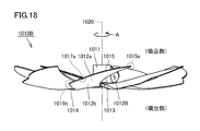
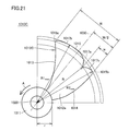
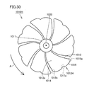
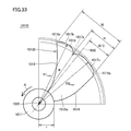
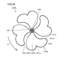
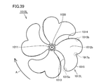
- Embodiment A1 of the present invention It is a partially exploded side view of the electric fan in Embodiment A1 of the present invention. It is the perspective view seen from the back side of the propeller fan in Embodiment A1 of this invention. It is the perspective view seen from the front side of the propeller fan in Embodiment A1 of this invention. It is a rear view of the propeller fan in Embodiment A1 of this invention. It is a front view of the propeller fan in Embodiment A1 of this invention. It is a side view of the propeller fan in Embodiment A1 of this invention. It is an enlarged back view which shows the shape of the blade
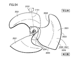
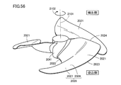
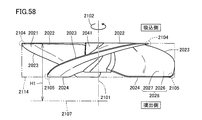
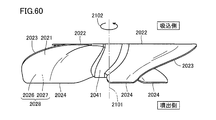
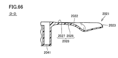
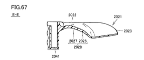
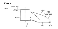
- FIG. 53 It is a perspective view which shows the circulator provided with the propeller fan in Embodiment B1 of this invention. It is the perspective view which looked at the propeller fan in Embodiment B1 of this invention from the suction side. It is another perspective view which looked at the propeller fan in FIG. 53 from the suction side. It is the top view which looked at the propeller fan in FIG. 53 from the suction side. It is the perspective view which looked at the propeller fan in FIG. 53 from the ejection side. It is the top view which looked at the propeller fan in FIG. 53 from the ejection side. It is a side view which shows the propeller fan in FIG. It is another side view which shows the propeller fan in FIG. FIG. 54 is still another side view showing the propeller fan in FIG.
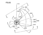
- FIG. 54 is still another side view showing the propeller fan in FIG. 53. It is the top view which expanded the propeller fan in FIG. 55 partially.
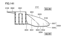
- FIG. 63 is a side view showing a propeller fan viewed from the AA line in FIG. 62.
- FIG. 63 is a cross-sectional view showing the propeller fan along the line BB in FIG. 62.
- FIG. 63 is a cross-sectional view showing the propeller fan along the line CC in FIG. 62.
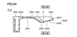
- FIG. 63 is a cross-sectional view showing the propeller fan along the line DD in FIG. 62.
- FIG. 63 is a cross-sectional view showing the propeller fan along the line EE in FIG. 62.
- FIG. 63 is a cross-sectional view showing the propeller fan along the line FF in FIG. 62.
- FIG. 63 is a cross-sectional view showing the propeller fan along the line GG in FIG. 62.
- FIG. 63 is a side view showing a propeller fan viewed from the line HH in FIG. 62. It is a side view which shows the 1st modification of the propeller fan in FIG. It is a side view which shows the 2nd modification of the propeller fan in FIG. It is a side view which shows the propeller fan in a comparative example.
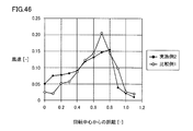
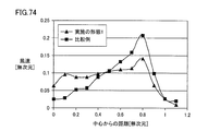
- FIG. 74 is a graph showing the relationship between the distance from the center of rotation and the wind speed in the propeller fan in the embodiment B1 in FIG. 53 and the propeller fan in the comparative example in FIG.
- FIG. 74 is a graph showing the relationship between the rotational speed and the air volume in the propeller fan in the embodiment B1 in FIG. 53, the propeller fan in the first modified example in FIG. 71, and the propeller fan in the comparative example in FIG. 73.
- FIG. 74 is a graph showing the relationship between air volume and power consumption in the propeller fan in Embodiment B1 in FIG. 53, the propeller fan in the first modification in FIG. 71, and the propeller fan in the comparative example in FIG. 73.
- FIG. 74 is a graph showing the relationship between the air volume and noise in the propeller fan in Embodiment B1 in FIG. 53, the propeller fan in the first modification in FIG.
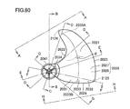
- FIG. 81 is a side view showing the propeller fan viewed from the AA line in FIG. 80.
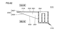
- FIG. 81 is a cross-sectional view showing the propeller fan along the line BB in FIG. 80.
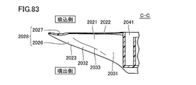
- FIG. 81 is a cross-sectional view showing the propeller fan along the line CC in FIG. 80.
- FIG. 81 is a cross-sectional view showing the propeller fan along the line DD in FIG. 80.
- FIG. 81 is a cross-sectional view showing the propeller fan along the line EE in FIG. 80.
- FIG. 81 is a cross-sectional view showing the propeller fan along the line FF in FIG. 80.
- FIG. 81 is a cross-sectional view showing the propeller fan along the line GG in FIG. 80.
- FIG. 81 is a side view showing the propeller fan viewed from the HH line in FIG. 80.
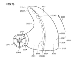
- FIG. 79 is a cross-sectional view along the line LXXIX-LXXXIX in FIG. 78.
- FIG. 79 is a cross-sectional view along the line XC-XC in FIG. 78.
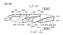
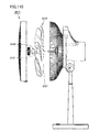
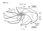
- FIG. 104 It is a figure which shows typically the state of the wind obtained when the propeller fan in Embodiment B3 of this invention is rotated at high speed. It is a side view which shows the electric fan provided with the propeller fan in Embodiment B4 of this invention. It is the perspective view which looked at the propeller fan in Embodiment B4 of this invention from the suction side. It is the perspective view which looked at the propeller fan in FIG. 104 from the ejection side. It is the top view which looked at the propeller fan in FIG. 104 from the suction side. It is the top view which looked at the propeller fan in FIG. 104 from the ejection side. It is a side view which shows the propeller fan in FIG.
- FIG. 111 It is sectional drawing which shows the metal mold
- 118 is a graph showing the relationship between the rotation speed and the air volume in the propeller fan in the second modified example in FIG. 118 and the propeller fan in the first comparative example in FIG. 120. 118 is a graph showing the relationship between the air volume and power consumption in the propeller fan in the second modified example in FIG.
- 118 is a graph showing the relationship between air volume and noise in the propeller fan in the second modified example in FIG. 118 and the propeller fan in the first comparative example in FIG. 120.
- 118 is a graph showing the relationship between the distance from the center of rotation and the wind speed in the propeller fan in the second modified example in FIG. 118 and the propeller fan in the first comparative example in FIG. 120.
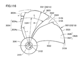
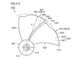
- 116 is a graph showing the relationship between the rotational speed and the air volume in the propeller fan in the embodiment C1 in FIG. 116, the propeller fan in the first modification in FIG. 117, and the propeller fan in the second comparative example in FIG.
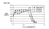
- 116 is a graph showing the relationship between air volume and power consumption in the propeller fan in the embodiment C1 in FIG. 116, the propeller fan in the first modification in FIG. 117, and the propeller fan in the second comparative example in FIG. 116 is a graph showing the relationship between the air volume and noise in the propeller fan in the embodiment C1 in FIG. 116, the propeller fan in the first modification in FIG. 117, and the propeller fan in the second comparative example in FIG. 116 is a graph showing the relationship between the distance from the rotation center and the wind speed in the propeller fan in the embodiment C1 in FIG. 116, the propeller fan in the first modified example in FIG. 117, and the propeller fan in the second comparative example in FIG. It is.
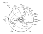
- FIG. 132 is a plan view partially showing the propeller fan in FIG. 131.
- FIG. 132 is another plan view partially showing the propeller fan in FIG. 131.
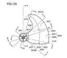
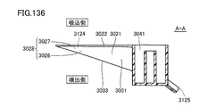
- FIG. 136 is a cross-sectional view showing the propeller fan along the line AA in FIG. 135.
- FIG. 136 is a cross-sectional view showing the propeller fan along the line BB in FIG. 135.
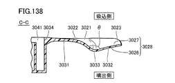
- FIG. 136 is a cross-sectional view showing the propeller fan along the line CC in FIG. 135.
- FIG. 136 is a cross-sectional view showing the propeller fan along the line DD in FIG. 135.
- FIG. 136 is a cross-sectional view showing the propeller fan along the line EE in FIG. 135.
- FIG. 136 is a cross-sectional view showing the propeller fan along the line FF in FIG. 135.
- FIG. 135 is a cross sectional view taken along the line CXLII-CXLII in FIG. 134.
- FIG. 135 is a cross sectional view taken along a line CXLIII-CXLIII in FIG. 134.
- Embodiment D1 of the present invention It is a partially exploded side view of the electric fan in Embodiment D1 of the present invention. It is the perspective view seen from the back side of the propeller fan in Embodiment D1 of this invention. It is the perspective view seen from the front side of the propeller fan in Embodiment D1 of this invention. It is a rear view of the propeller fan in Embodiment D1 of this invention. It is a front view of the propeller fan in Embodiment D1 of this invention. It is a side view of the propeller fan in Embodiment D1 of this invention. It is a conceptual diagram which shows the flow of the wind obtained when a propeller fan is rotated at low speed in the electric fan in Embodiment D1 of this invention.
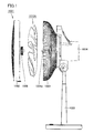
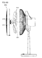
- FIG. 1 is a partially exploded side view of the electric fan according to Embodiment A1 of the present invention. First, with reference to this FIG. 1, the electric fan 1001 as a fluid feeder in this Embodiment is demonstrated.
- the electric fan 1001 mainly includes a front guard 1002, a rear guard 1003, a main body 1004, a stand 1005, and a propeller fan 1010A.
- the main body 1004 is supported by a stand 1005, and a drive motor (not shown) is accommodated therein.
- a rotation shaft 1004a of the drive motor is located on the front surface of the main body portion 1004, and a boss hub portion 1011 (see FIG. 2 and the like) as a rotation shaft portion of a propeller fan 1010A described later is screwed to the rotation shaft 1004a. It is fixed using a cap 1006.
- the front guard 1002 and the rear guard 1003 are provided so as to surround the propeller fan 1010A fixed to the main body 1004. More specifically, the rear guard 1003 is fixed to the main body 1004 so as to cover the back side of the propeller fan 1010A, and the front guard 1002 is fixed to the rear guard 1003 so as to cover the front side of the propeller fan 1010A.
- the stand 1005 is provided to place the electric fan 1001 on the floor or the like, and supports the main body 1004. In addition, at a predetermined position of the stand 1005, an operation unit (not shown) for turning on / off the electric fan 1001, switching the operation state, and the like is provided.
- main body 1004 and the stand 1005 are preferably connected so that the main body 1004 can swing in a horizontal plane and a vertical plane so that the electric fan 1001 has a neck swing function. .
- the stand 1005 is configured to be stretchable along the vertical direction so that the electric fan 1001 has a height adjusting function.
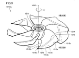
- FIGS. 2 and 3 are perspective views of the propeller fan according to the present embodiment as viewed from the rear side and the front side
- FIGS. 4 to 6 are a rear view, a front view, and a side view of the propeller fan according to the present embodiment.
- FIG. Next, the basic structure of propeller fan 1010A in the present embodiment will be described with reference to FIGS.
- the propeller fan 1010A includes the above-described boss hub portion 1011 as a rotating shaft portion and a plurality of smoothly bent plate-like blades 1012A.
- the boss hub portion 1011 has a bottomed substantially cylindrical shape, and each of the plurality of blades 1012A is directed radially outward from the outer peripheral surface of the boss hub portion 1011 so as to be aligned along the circumferential direction of the boss hub portion 1011. Projecting.
- Propeller fan 1010A in the present embodiment has seven blades, and is a resin molding in which boss hub portion 1011 and seven blades 1012A are integrally molded with a synthetic resin such as AS (acrylonitrile-styrene) resin. It is composed of products.
- AS acrylonitrile-styrene
- the boss hub portion 1011 rotates in the direction of arrow A shown in the figure with the virtual center axis 1020 as the center of rotation when driven by the drive motor described above.
- the entire propeller fan 1010A rotates in the direction of arrow A shown in the drawing with the central axis 1020 described above as the center of rotation, and a plurality of blades 1012A provided side by side along the circumferential direction of the boss hub portion 1011. Will also rotate around the central axis 1020 described above.
- the plurality of blades 1012A are arranged at equal intervals so as to be separated from each other along the rotation direction, and each of the plurality of blades 1012A has the same shape. . Therefore, when one of the blades 1012A is rotated about the central axis 1020 as the rotation center, the shape of the blade 1012A matches the shape of another blade 1012A.
- the blades 1012A extend along the rotation direction of the propeller fan 1010A, the front edge portion 1013 located on the front side in the rotation direction of the propeller fan 1010A, the rear edge portion 1014 located on the rear side in the rotation direction of the propeller fan 1010A, and the propeller fan 1010A. And an outer edge portion 1015. That is, in a state in which propeller fan 1010A is viewed in plan along central axis 1020, the outer shape of blade 1012A is the front edge portion 1013, rear edge portion 1014, and outer edge portion 1015 except for the portion connected to boss hub portion 1011. It will be prescribed by.
- the front edge portion 1013 and the rear edge portion 1014 extend outward in the radial direction from the boss hub portion 1011.
- both the front edge portion 1013 and the rear edge portion 1014 are gradually positioned on the front side in the rotational direction from the radially inner side toward the outer side. As a whole, it has a generally arcuate shape.
- the leading edge 1013 is A portion having a certain height is included between the inner end and a position spaced radially outward.
- the front edge portion 1013 A portion closer to the radially inner side connected to the boss hub portion 1011 extends so as to overlap the suction side end surface.
- the portion of the front edge portion 1013 closer to the outer side in the radial direction does not overlap the suction side end surface, and is provided closer to the ejection side than the suction side end surface as a whole.
- the radial direction including the outer end of the trailing edge 1014 is configured such that its height increases from the radially inner side toward the radially outer side.
- the trailing edge 1014 is In other words, it is configured to move away from the ejection side end face as it goes radially outward. That is, the portion of the rear edge portion 1014 closer to the outside in the radial direction does not overlap the ejection side end surface, and is provided closer to the suction side than the ejection side end surface as a whole.
- the wing 1012A is configured so that the width along the rotation direction is reduced, and the front edge portion 1013 and the rear edge portion are formed.
- the blades 1012A are configured so that their widths along the rotation direction are increased.
- the outer end located on the radially outer side of the front edge portion 1013 is connected to the front end 1015a in the rotational direction of the outer edge portion 1015, and the outer end located on the radially outer side of the rear edge portion 1014 is rotated by the outer edge portion 1015. It is connected to the rear end 1015b in the direction. That is, the outer edge portion 1015 is configured to connect the outer end of the front edge portion 1013 and the outer end of the rear edge portion 1014 along the rotational direction, and has a generally arcuate shape as a whole.
- the outer edge portion 1015 is positioned away from the suction side end surface along the direction in which the central axis 1020 extends, and the entire outer edge portion 1015 extends from the ejection side end surface along the direction in which the central axis 1020 extends. They are located apart. That is, the outer edge portion 1015 does not overlap the suction side end surface and the ejection side end surface at any position, and is provided closer to the inside than the suction side end surface and the ejection side end surface as a whole.
- each of the front edge portion 1013 and the rear edge portion 1014 is formed to have a generally arcuate shape, thereby forming a smooth shape.
- the outer edge portion 1015 is formed to have a generally arcuate shape so as to have a smooth shape. For this reason, the front end 1015a and the rear end 1015b of the outer edge portion 1015 described above have curvatures that are maximal at least in the vicinity thereof.
- the front end 1015a of the outer edge portion 1015 described above has a sickle-pointed shape in a state in which the propeller fan 1010A is viewed in plan along the central axis 1020.
- the sickle-shaped front end 1015a is disposed at the most forward position of the wing 1012A in the rotation direction.
- the front edge portion 1013 and the outer edge portion 1015 located in the vicinity of the front end 1015a are portions located forward in the rotation direction, and thus correspond to blade tip portions where blade tip vortices are generated.
- the blade 1012A is formed with a blade surface for blowing air as the propeller fan 1010A rotates (that is, sending air from the suction side to the ejection side).
- the blade surface includes a negative pressure surface 1012a corresponding to the back surface of the blade 1012A located on the suction side and a positive pressure surface 1012b corresponding to the front surface of the blade 1012A located on the ejection side, both of which are described above. It is formed in a region surrounded by the edge portion 1013, the rear edge portion 1014, and the outer edge portion 1015.
- the negative pressure surface 1012a and the positive pressure surface 1012b which are blade surfaces, both incline from the ejection side to the suction side of the propeller fan 1010A along the rotation direction of the propeller fan 1010A from the rear edge portion 1014 toward the front edge portion 1013. It is composed of a curved surface.
- the blade 1012A has a blade inner region 1018a and a blade outer region 1018b having mutually different blade surface shapes (see FIG. 7).
- the blade inner region 1018a corresponds to a region located on the boss hub portion 1011 side of the blade 1012A
- the blade outer region 1018b corresponds to a region located on the outer edge portion 1015 side of the blade 1012A.
- the blade 1012A includes a blade inner region 1018a located on the boss hub portion 1011 side, a blade outer region 1018b located on the outer edge portion 1015 side, and a blade inner region such that the negative pressure surface 1012a side is concave and the positive pressure surface 1012b side is convex.
- the connecting portion 1016 has a surface curvature that is maximal in the vicinity thereof, and appears as a curved concave groove portion on the suction surface 1012a, and as a protrusion protruding in a curved shape on the pressure surface 1012b. Appears.
- the connecting portion 1016 is provided substantially along the rotation direction, and extends from a position in the vicinity of the front end 1015a of the outer edge portion 1015 toward a position in the middle of the rear edge portion 1014 in the radial direction.
- the blade 1012A when viewed along the rotation direction of the propeller fan 1010A, becomes thicker from the front edge portion 1013 and the rear edge portion 1014 toward the blade center and the leading edge than the blade center.
- An airfoil shape having a maximum thickness is formed at a position close to the portion 1013 side.
- the outer edge portion 1015 of the blade 1012A is positioned on the front outer edge portion 1017b (see FIG. 7) located on the front edge portion 1013 side and on the rear edge portion 1014 side.
- FIG. 7 is an enlarged rear view showing the shape of the blades of the propeller fan in the present embodiment.
- the outer edge portion 1015 of the wing 1012 ⁇ / b> A is formed with a connection portion 1017 a having a shape that is recessed toward the central axis 1020 side.
- the connection portion 1017a is formed at a position midway between the front end 1015a and the rear end 1015b of the outer edge portion 1015.
- the outer edge portion 1015 of the wing 1012A has a front outer edge portion 1017b positioned on the front end 1015a side of the outer edge portion 1015 and a rear end 1015b side of the outer edge portion 1015.
- a rear outer edge portion 1017c is provided.
- the connecting portion 1017a is preferably formed so as to have a smoothly curved shape as shown in the figure, but this is not necessarily a curved shape and may be a bent shape. Further, in the present embodiment, since the connection portion 1017a is formed so as to be recessed relatively shallowly, the connection portion 1017a has a substantially obtuse angle shape.
- connection portion 1017a is formed is not particularly limited as long as it is a position on the outer edge portion 1015.
- the connection portion 1017a is located near the rear end 1015b of the outer edge portion 1015. Is formed. Therefore, in the present embodiment, the width along the rotation direction of the front outer edge portion 1017b is formed larger than the width along the rotation direction of the rear outer edge portion 1017c.
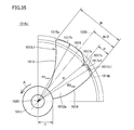
- a bisector 1030 having an angle formed by a line segment connecting the rear end 1015b of the outer edge 1015 and the central axis 1020 is drawn, the front end 1015a and the rear along the direction perpendicular to the bisector 1030 are drawn.
- the distance between the end 1015b is W
- the distance between the rear end 1015b along the direction perpendicular to the bisector 1030 and the most radially inner point of the connecting portion 1017a is w.
- the distance W and the distance w satisfy the condition of W / 2> w.
- the maximum radius R2 max from the central axis 1020 of 1017c satisfies the condition of R1 max > R2 max .
- the central axis 1020 at the point located on the innermost radial direction of the connecting portion 1017a in a state where the blade 1012A is viewed in plan along the central axis 1020. If the radius from is R, the radius R and the maximum radius R2 max satisfy the condition of R ⁇ R2 max .
- the wind speed distribution in the radial direction can be made more uniform, and the unevenness of the wind speed can be suppressed, so that the wind with good wind perception can be obtained.
- the outer edge is compared with the case where the recessed connection portion 1017a is not formed on the outer edge portion 1015.
- the blade area decreases in the vicinity of the portion 1015 (that is, the portion closer to the outside in the radial direction). Therefore, the wind speed that increases in proportion to the outer side in the radial direction is moderated in the portion closer to the outer edge portion 1015, and the wind speed generated in the portion closer to the inner side in the radial direction is closer to the outer edge portion 1015.
- the wind speed of the wind generated in the part approaches, and the wind speed distribution in the radial direction becomes more uniform. Therefore, unevenness in the wind speed can be suppressed, and a wind with good wind perception can be obtained.
- the wing 1012A having the above-described configuration, it is possible to generate a wind with good wind perception, in which the pressure fluctuation included in the wind generated in the radially outer portion is reduced.
- the present embodiment since it has a wing shape in which the outer edge portion 1015 is formed with a hollow-shaped connection portion 1017a, it is between the front outer edge portion 1017b and the rear outer edge portion 1017c of one wing 1012A.
- a relatively small space that is, a space where the depression-shaped connecting portion 1017a is located
- the space exists as a space that does not generate wind in the wing 1012A.
- the front outer edge portion 1017b and the rear outer edge portion 1017c provided on one wing 1012A play an approximate role as if air is blown by two wings. It is possible to generate a breeze with a small pressure fluctuation.
- the details of the effect will be more specifically referred to in the embodiment A2 of the present invention described later.
- FIG. 8 is a conceptual diagram showing the flow of wind obtained when the propeller fan is rotated at a low speed in the electric fan according to the present embodiment
- FIG. 9 is a diagram of the wind obtained when the propeller fan is rotated at a low speed. It is a figure which shows a state typically.
- FIG. 10 is a conceptual diagram showing the flow of wind obtained when the propeller fan is rotated at a high speed in the electric fan according to the present embodiment
- FIG. 11 is obtained when the propeller fan is rotated at a high speed. It is a figure which shows the state of a wind typically.
- the trajectory of the wing tip vortex generated in the vicinity of the front end 1015a of the outer edge portion 1015 is schematically shown by a broken line.
- the trajectory of the wind generated at a position near the outer edge portion 1015 of the wing 1012A is schematically shown by a thick line.
- the recessed connection portion 1017a is formed at a position on the outer edge portion 1015 of the wing 1012A.
- the position on the outer edge portion 1015 corresponds to a position along the streamline of the blade tip vortex flowing on the blade surface on the downstream side of the blade tip portion including the front end 1015a of the outer edge portion 1015.
- the wind generated by the blades 1012A converges in front of the electric fan 1001, and the wind 1300 that travels far and has high straightness can be blown. Therefore, it is possible to blow air efficiently, and the generation of noise can be suppressed by increasing the straightness of the wind.
- the propeller fan 1010A and the electric fan 1001 provided with the propeller fan 1010A in this embodiment it is possible to send out a wind having a small variation in the pressure of the generated wind and good wind perception, and to reduce noise. It becomes possible to plan.
- the propeller fan 1010A according to the present embodiment can provide the following effects.
- the portion excluding the portion on the outer side in the radial direction of the front edge portion 1013 is configured to be located on the suction side end surface. Therefore, it is possible to increase the blowing capacity in the portion closer to the radially inner side of the blade 1012A, and it is possible to increase the wind speed of the wind generated in the portion closer to the radially inner side, which occurs in the portion closer to the outer edge portion 1015. This approaches the wind speed of the wind, and the wind speed distribution in the radial direction becomes more uniform. Therefore, unevenness in the wind speed can be suppressed, and a wind with good wind perception can be obtained.
- the rear edge portion 1014 is configured to be separated from the ejection side end surface as it goes outward in the radial direction. Therefore, the wind speed that increases in proportion to the outer side in the radial direction is moderated in the portion closer to the outer edge portion 1015, and the wind speed generated in the portion closer to the inner side in the radial direction is closer to the outer edge portion 1015.
- the wind speed of the wind generated in the part approaches, and the wind speed distribution in the radial direction becomes more uniform. Therefore, unevenness in the wind speed can be suppressed, and a wind with good wind perception can be obtained.
- a connecting portion 1016 is provided to bend and connect these at the boundary between the blade inner region 1018a and the blade outer region 1018b. For this reason, a horseshoe vortex is generated on the connecting portion 1016, and the mainshoe vortex suppresses separation of the mainstream flowing on the wing surface, so that noise is reduced and blowing capacity is increased. Become. Further, as described above, in the present embodiment, since the connecting portion 1016 is provided substantially along the rotation direction, the wing tip vortex is also connected in addition to the horseshoe vortex generated on the connecting portion 1016. It is held on the portion 1016, and the mainstream separation can be further suppressed. In addition, the connection part 1016 does not need to be curved, for example, may be bent.
- the entire outer edge portion 1015 is positioned away from the suction side end surface along the direction in which the central axis 1020 extends, and the entire outer edge portion 1015 is the central axis. It is located away from the ejection side end face along the direction in which 1020 extends. For this reason, the overall thickness of the blade 1012A of the propeller fan 1010A in the direction along the central axis 1020 is greatly reduced in the radially outer portion, so that the gap between the front guard 1002 and the rear guard 1003 described above is reduced. A large distance can be secured in this portion. Therefore, it is possible to suppress the occurrence of finger pinching or the like in the electric fan 1001, and it is possible to improve safety.
- the first verification test a plurality of samples having different positions along the rotational direction and the radial direction of the connecting portion provided on the outer edge portion are prepared, and each sample is rotated based on this, and the air volume obtained at that time And the pressure fluctuation contained in the obtained wind was measured.
- the wing inner region and the wing outer region are not configured to have different wing surface shapes, but the entire wing surface is configured to have a single wing surface shape. .
- the position where the connecting portion is provided is determined in advance, and the parallelogram having the connecting portion as one vertex is a portion near the rear end of the blade and the trailing edge of the blade. I drew it on the part near the outer edge of the part, and decided to cut out a part of the wing in a form that was almost along the parallelogram.
- the outer edge is formed so that both the front outer edge portion and the rear outer edge portion formed using the connection portion and the connection portion as a boundary have a smooth shape. The part was curved appropriately.
- both are located at a position 30 mm away on the ejection side along the central axis of the propeller fan, and the distance along the radial direction from the rotation center of the propeller fan is 70% of the maximum radius of the outer edge portion.
- the measurement was performed at a position corresponding to the position.
- the position corresponding to the position where the distance along the radial direction from the rotation center of the propeller fan is 70% of the maximum radius of the outer edge is generally the position where the wind speed is the largest, and therefore the position where the pressure fluctuation is most likely to occur. is there.
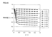
- FIG. 12 is a graph showing the relationship between the blade shape and the relative airflow obtained in the first verification test.
- the horizontal axis represents the position along the rotation direction of the connecting portion
- the vertical axis represents the relative air volume.
- ⁇ shown on the horizontal axis is a value expressed by w / W using the above-described distance W and distance w
- ⁇ is the above-mentioned maximum radius R1 max , radius R, and radius r of the boss hub (see FIG. 7), (R1 max -R) / (R1 max -r).
- the relative air volume shown on the vertical axis is a value obtained by dividing the air volume measured in each sample by the air volume in a propeller fan in which no hollow connection portion is formed on the outer edge.
- the air volume tends to gradually decrease as the connecting portion moves from the rear end to the front end of the outer edge.
- the connecting portion is close to the front end of the outer edge portion along the rotation direction, there is no tendency for the air volume to further decrease.
- the air volume tends to gradually decrease as the connecting portion moves from the position near the outer edge portion toward the position near the rotation center along the radial direction.
- FIG. 13 is a graph showing the relationship between the blade shape and the relative pressure fluctuation obtained in the first verification test.
- the horizontal axis represents the position along the rotation direction of the connecting portion
- the vertical axis represents the relative pressure fluctuation.
- the relative pressure fluctuation shown on the vertical axis is obtained by dividing the maximum value of the pressure difference measured in each sample by the maximum value of the pressure difference in the propeller fan in which no hollow connection portion is formed on the outer edge. It is the value.
- the pressure variation tends to gradually decrease as the connecting portion moves from the position near the rear end toward the position near the front end along the rotation direction. Further, it is understood that the pressure fluctuation tends to further decrease as the connecting portion moves from the position near the outer edge portion toward the position near the rotation center along the radial direction.
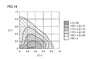
- FIG. 14 is a contour diagram showing the relationship between the wing shape and the comfort index obtained in the first verification test.
- the contour diagram represents the result of the first verification test as the fan performance including the comfort index ⁇ based on the results shown in FIGS. 12 and 13 described above.
- the comfort index ⁇ is calculated by dividing the relative air volume shown in FIG. 12 by the relative pressure fluctuation shown in FIG. 13, and the higher this value, the higher the comfort.
- the horizontal axis represents the position along the rotation direction of the connecting portion
- the vertical axis represents the position along the radial direction of the connecting portion.
- the comfort index ⁇ is reliably improved by 10% or more as compared with the propeller fan in which the concave connection portion is not formed.
- the propeller fan according to the comparative example 1 has a single blade surface shape in which a hollow connection portion is not formed at the outer edge portion. Are different from each other in that the front edge portion is formed so as to be inclined substantially monotonously along the radial direction. In other respects, the front edge portion has a common shape. It was.
- the wind speed is measured at a position 30 mm away on the ejection side along the central axis of the propeller fan, and the distance from the central axis is the outer edge in order to grasp the radial distribution.
- the center axis is arranged in increments of 0.1 times up to a position corresponding to a position that is 1.1 times the maximum radius.
- FIG. 15 is a graph showing the relationship between the distance from the rotation center of the propeller fan according to Example 1 and Comparative Example 1 and the wind speed obtained in the second verification test.
- the horizontal axis represents the distance from the center of rotation
- the vertical axis represents the wind speed.
- the distance from the rotation center is represented by a dimensionless value where the position corresponding to the rotation center is 0 and the position corresponding to the outer edge is 1, and the vertical axis indicates the first embodiment.
- the air volumes are matched, and the wind speed is represented by a dimensionless value obtained by dividing the measured value of each wind speed by the air volume.
- the wind speed is small on the radially inner side, and gradually increases toward the radially outer side, which is 0.7 times the maximum radius of the outer edge portion. At the position, the wind speed shows the maximum value, and the wind speed tends to gradually decrease toward the outer side in the radial direction.
- the wind speed is larger on the inner side in the radial direction than that in Comparative Example 1, and there is almost no change in the wind speed toward the outer side in the radial direction. There is a tendency that the wind speed begins to decrease at a position of 7 times and gradually decreases toward the outside in the radial direction.
- the maximum value of the wind speed was lower in Example 1 than in Comparative Example 1.
- the wind speed distribution along the radial direction is greatly uniformed, and it is possible to suppress the unevenness of the wind speed and the wind with good wind perception. It was confirmed that it can be.
- FIG. 16 is a schematic sectional view showing a propeller fan molding die in the present embodiment.
- a propeller fan molding die 1100 according to the present embodiment will be described with reference to FIG.
- propeller fan 1010A in the present embodiment is formed of a resin molded product.
- a molding die 1100 for injection molding as shown in FIG. 16 is used.
- the molding die 1100 includes a fixed side die 1101 and a movable side die 1102.
- the fixed mold 1101 and the movable mold 1102 define a cavity 1103 having substantially the same shape as the propeller fan 1010A and into which a fluid resin is injected.
- the molding die 1100 may be provided with a heater (not shown) for improving the fluidity of the resin injected into the cavity 1103.
- a heater for improving the fluidity of the resin injected into the cavity 1103.
- the installation of such a heater is particularly effective when, for example, a synthetic resin with increased strength such as an AS resin containing glass fiber is used.
- the surface on the positive pressure surface 1012b side of the propeller fan 1010A is molded by the fixed die 1101, and the surface on the negative pressure surface 1012a side is molded by the movable die 1102.
- the surface on the negative pressure surface 1012a side of the propeller fan 1010A may be formed by the fixed mold 1101 and the surface on the positive pressure surface 1012b side of the propeller fan 1010A may be formed by the movable mold 1102.
- a propeller fan that uses metal as a material and is integrally formed by drawing by press working.
- a thin metal plate is generally used because it is difficult to draw with a thick metal plate and the mass becomes heavy. In this case, it is difficult to maintain strength (rigidity) with a large propeller fan.
- a part that uses a part called a spider formed of a metal plate thicker than the wing part and fixes the wing part to the rotating shaft but there is a problem that the mass becomes heavy and the fan balance is also deteriorated.
- a thin metal plate having a certain thickness is used, there is a problem that the cross-sectional shape of the wing cannot be a wing shape.
- a boss hub provided for inserting the rotating shaft 1004a in order to further reduce noise as a countermeasure against cocking noise unique to the DC motor.
- a cylindrical rubber boss may be insert-molded in the shaft hole of the portion 1011. In that case, a rubber boss as an insert part may be installed in a mold for molding the surface on the suction surface 1012a side of the propeller fan 1010A prior to injection molding.
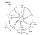
- propeller fans 1010B to 1010K according to the first to tenth modifications based on the above-described embodiment will be described.
- Propeller fans 1010B to 1010K according to the first to tenth modifications shown below are basically in the shape and position of propeller fan 1010A in the above-described embodiment and connecting portion 1017a provided on outer edge portion 1015. It is different.
- FIG. 17 and 18 are a rear view and a side view of the propeller fan according to the first modification
- FIG. 19 is an enlarged rear view showing the shape of the blades of the propeller fan according to the first modification.
- propeller fan 1010B has a blade surface shape in which the blade inner region and the blade outer region are different from propeller fan 1010A in the present embodiment described above.
- the entire blade surface is configured to have a single blade surface shape without being configured as described above, and the entire outer edge portion 1015 extends from the suction side end surface along the direction in which the central axis 1020 extends. It is different in that it is not spaced apart, and other configurations have the same configuration as propeller fan 1010A in the present embodiment described above.
- the outer edge portion 1015 is provided with a recessed connection portion 1017a, so that the outer edge portion 1015 of the wing 1012B has a front outer edge portion 1017b positioned on the front end 1015a side of the outer edge portion 1015 and the outer edge portion 1015B.
- a rear outer edge portion 1017c located on the rear end 1015b side of the outer edge portion 1015 is provided.
- the connection portion 1017a is formed so as to be recessed relatively shallowly, and thus the connection portion 1017a has a substantially obtuse angle shape.
- the distance W and the distance w satisfy the condition of W / 2> w
- the maximum radius R1 max and the maximum radius R2 max are , R1 max > R2 max is satisfied, and the radius R and the maximum radius R2 max satisfy the condition of R ⁇ R2 max .
- (Second modification) 20 and 21 are a rear view of a propeller fan according to a second modification and an enlarged rear view showing the shape of a blade.
- the propeller fan 1010C according to the second modified example is only in the shape of the propeller fan 1010B according to the first modified example described above and the recessed connection portion 1017a provided in the outer edge portion 1015.
- the other configurations are the same as those of the propeller fan 1010B according to the first modification described above.
- connection portion 1017a provided on outer edge portion 1015 is formed to be recessed relatively deep, and connection portion 1017a has a substantially acute angle shape.
- the distance W and the distance w satisfy the condition of W / 2> w
- the maximum radius R1 max and the maximum radius R2 max are , R1 max > R2 max is satisfied, and the radius R and the maximum radius R2 max satisfy the condition of R ⁇ R2 max .
- the same effect as that obtained in the first modified example described above can be obtained, and the pressure fluctuation of the generated wind is small and it is possible to send out a wind with good wind perception. At the same time, noise is reduced.
- the air velocity distribution along the radial direction is made more uniform by the size of the recessed connection portion 1017a provided in the outer edge portion 1015 than in the first modification described above. It can be realized effectively.
- (Third Modification) 22 and 23 are a rear view of a propeller fan according to a third modification and an enlarged rear view showing the shape of a blade.
- the propeller fan 1010D according to the third modified example is only in the shape of the propeller fan 1010B according to the first modified example described above and the recessed connecting portion 1017a provided in the outer edge portion 1015.
- the other configurations are the same as those of the propeller fan 1010B according to the first modification described above.
- connection portion 1017a provided on outer edge portion 1015 is formed to be recessed relatively deep, and connection portion 1017a has a substantially obtuse angle shape.
- the distance W and the distance w satisfy the condition of W / 2> w
- the maximum radius R1 max and the maximum radius R2 max are , R1 max > R2 max is satisfied, and the radius R and the maximum radius R2 max satisfy the condition of R ⁇ R2 max .
- the same effect as that obtained in the first modified example described above can be obtained, and the pressure fluctuation of the generated wind is small and it is possible to send out a wind with good wind perception. At the same time, noise is reduced.
- the air velocity distribution along the radial direction is made more uniform as the hollow connection portion 1017a provided in the outer edge portion 1015 is larger than the first modified example described above. It can be realized effectively.
- (Fourth modification) 24 and 25 are a rear view of a propeller fan according to a fourth modification and an enlarged rear view showing the shape of a blade.
- the propeller fan 1010E according to the fourth modified example is only in the shape of the propeller fan 1010B according to the first modified example described above and the connection portion 1017a having a hollow shape provided in the outer edge portion 1015.
- the other configurations are the same as those of the propeller fan 1010B according to the first modification described above.
- the connection portion 1017a provided on the outer edge portion 1015 is formed such that the front outer edge portion 1017b and the rear outer edge portion 1017c form a step, and the rear outer edge portion 1017c
- the maximum radius R2 max is configured to be smaller than the maximum radius R1 max of the front outer edge portion 1017b.
- the distance W and the distance w satisfy the condition of W / 2> w
- the maximum radius R1 max and the maximum radius R2 max are , R1 max > R2 max
- 5th modification 26 and 27 are a rear view of a propeller fan according to a fifth modification and an enlarged rear view showing the shape of a blade.
- the propeller fan 1010F according to the fifth modified example is only in the shape of the propeller fan 1010B according to the first modified example described above and the recessed connecting portion 1017a provided in the outer edge portion 1015.
- the other configurations are the same as those of the propeller fan 1010B according to the first modification described above.
- the connection portion 1017a provided on the outer edge portion 1015 is formed such that a front outer edge portion 1017b and a rear outer edge portion 1017c form a step, and the rear outer edge portion 1017c
- the maximum radius R2 max is configured to be significantly smaller than the maximum radius R1 max of the front outer edge portion 1017b.
- the distance W and the distance w satisfy the condition of W / 2> w
- the maximum radius R1 max and the maximum radius R2 max are , R1 max > R2 max is satisfied, and the radius R and the maximum radius R2 max satisfy the condition of R> R2 max .
- the same effect as that obtained in the first modified example described above can be obtained, and the pressure fluctuation of the generated wind is small and it is possible to send out a wind with good wind perception. At the same time, noise is reduced.
- the air velocity distribution along the radial direction is made more uniform by the size of the recessed connection portion 1017a provided in the outer edge portion 1015 than in the first modification described above. It can be realized effectively.
- (Sixth Modification) 28 and 29 are a rear view of a propeller fan according to a sixth modification and an enlarged rear view showing the shape of a blade.
- the propeller fan 1010G according to the sixth modified example is only in the shape of the propeller fan 1010B according to the first modified example described above and the recessed connecting portion 1017a provided in the outer edge portion 1015.
- the other configurations are the same as those of the propeller fan 1010B according to the first modification described above.
- the connection portion 1017a provided in the outer edge portion 1015 is formed so as to be recessed relatively deeply, and the recess-shaped connection portion 1017a has a wedge shape. It is formed in a sharp and sharp corner.
- the distance W and the distance w satisfy the condition of W / 2> w
- the maximum radius R1 max and the maximum radius R2 max are , R1 max > R2 max is satisfied, and the radius R and the maximum radius R2 max satisfy the condition of R ⁇ R2 max .
- the same effect as that obtained in the first modified example described above can be obtained, and the pressure fluctuation of the generated wind is small and it is possible to send out a wind with good wind perception. At the same time, noise is reduced.
- the front outer edge portion 1017b and the rear outer edge portion 1017c provided on one blade 1012G are blown by two blades. As a result, the effect of fulfilling the role of approximation will appear more clearly, and it will be possible to more effectively realize a wind with good wind perception with a small pressure fluctuation as a whole.
- a horseshoe vortex is generated in the portion where the connection portion 1017a is provided, and the horseshoe vortex suppresses separation of the mainstream flowing on the wing surface. Is reduced and the air blowing capability is increased. Furthermore, since the tip of the rear outer edge portion 1017c in the rotation direction is located on the front side in the rotation direction of the connection portion 1017a, the wing tip vortex in addition to the horseshoe vortex generated on the connection portion 1017a is also connected to the connection portion 1017a. It will be held at the top, and the mainstream separation can be further suppressed.
- (Seventh Modification) 30 and 31 are a rear view of a propeller fan according to a seventh modification and an enlarged rear view showing the shape of a blade.
- the propeller fan 1010H according to the seventh modified example is only at the position of the propeller fan 1010B according to the first modified example described above and the recess-shaped connecting portion 1017a provided on the outer edge portion 1015.
- the other configurations are the same as those of the propeller fan 1010B according to the first modification described above.
- connection portion 1017a is provided at the center portion along the rotation direction of outer edge portion 1015.
- the maximum radius R1 max and the maximum radius R2 max are , R1 max > R2 max is satisfied, and the radius R and the maximum radius R2 max satisfy the condition of R ⁇ R2 max .
- (Eighth modification) 32 and 33 are a rear view of a propeller fan according to an eighth modification and an enlarged rear view showing the shape of a blade.
- the propeller fan 1010I according to the eighth modified example is only at the position of the propeller fan 1010B according to the first modified example described above and the recessed connecting portion 1017a provided in the outer edge portion 1015.
- the other configurations are the same as those of the propeller fan 1010B according to the first modification described above.
- a connection portion 1017a is provided at a position near the front end 1015a of the outer edge portion 1015.
- the distance W and the distance w satisfy the condition of W / 2 ⁇ w
- the maximum radius R1 max and the maximum radius R2 max are , R1 max > R2 max is satisfied
- the radius R and the maximum radius R2 max satisfy the condition of R ⁇ R2 max .
- (Ninth Modification) 34 and 35 are a rear view of a propeller fan according to a ninth modification and an enlarged rear view showing the shape of a blade.
- the propeller fan 1010J according to the ninth modification differs from the propeller fan 1010D according to the third modification described above only in the shape of the rear outer edge portion 1017c provided on the outer edge portion 1015.
- the configuration is the same as that of the propeller fan 1010D according to the third modification described above.
- the propeller fan 1010J has a configuration in which a plurality of recesses 17c1 are further provided in a rear outer edge portion 1017c formed by providing a recess-shaped connection portion 1017a in the outer edge portion 1015. .
- the recess 17c1 has a recess shape smaller than the connection portion 1017a provided on the outer edge portion 1015. Therefore, the propeller fan 1010J according to the ninth modification example as a whole is a propeller according to the third modification example.
- the shape is similar to that of the fan 1010D.
- the number of depressions 17c1 is not limited to two as shown in the drawing, and may be one or three or more.
- the distance W and the distance w satisfy the condition of W / 2> w
- the maximum radius R1 max and the maximum radius R2 max are , R1 max > R2 max is satisfied, and the radius R and the maximum radius R2 max satisfy the condition of R ⁇ R2 max .
- FIG. 36 is an enlarged rear view showing the shape of the blades of the propeller fan according to the tenth modification. As shown in FIG. 36, in the propeller fan 1010K according to the tenth modification, each of the plurality of blades protruding from the boss hub portion 1011 toward the radially outer side has a different shape.
- each wing blade does not necessarily need to be the same, You may be comprised so that it may mutually differ.
- FIG. 37 is a perspective view seen from the back side of the propeller fan according to Embodiment A2 of the present invention
- FIGS. 38 to 40 are a rear view, a front view, and a side view of the propeller fan according to this embodiment.
- FIG. 41 is an enlarged rear view showing the shape of the blades of the propeller fan in the present embodiment.
- propeller fan 1010L according to the present embodiment will be described with reference to FIGS. Note that propeller fan 1010L in the present embodiment is mounted and used in electric fan 1001, similarly to propeller fan 1010A shown in the above-described embodiment A1.
- propeller fan 1010L in the present embodiment has four blades, and each blade 1012L has a propeller according to the first modification based on embodiment A1 described above.
- the fan 1010B has a smooth front edge portion 1013, a rear edge portion 1014, and an outer edge portion 1015 that are more curved than the blades 1012B.
- the basic structure of the blade 1012L provided in the propeller fan 1010L in the present embodiment except that the front edge portion 1013, the rear edge portion 1014, and the outer edge portion 1015 are more curved and smooth. This is the same as that of the blade 1012B provided in the propeller fan 1010B according to the first modification based on the embodiment A1 described above.
- the shape of the blade 1012L provided in the propeller fan 1010L will be described in more detail.
- the outer edge portion 1015 of the wing 1012L is formed with a connection portion 1017a having a shape that is recessed toward the central axis 1020 side.
- the connection portion 1017a is formed at a position midway between the front end 1015a and the rear end 1015b of the outer edge portion 1015.
- the outer edge portion 1015 of the wing 1012L has a front outer edge portion 1017b (see FIG. 41) positioned on the front end 1015a side of the outer edge portion 1015, and an outer edge portion 1015.
- a rear outer edge portion 1017c (see FIG. 41) located on the rear end 1015b side is provided.
- connection portion 1017a is preferably formed so as to have a smoothly curved shape as shown in the figure, but this is not necessarily a curved shape and may be a bent shape. In the present embodiment, since connection portion 1017a is formed so as to be recessed relatively deeply, connection portion 1017a has a substantially acute angle shape.
- the position where the connecting portion 1017a is formed is not particularly limited as long as it is a position on the rear end 1015b side of the center portion along the rotation direction of the outer edge portion 1015.
- the outer edge portion is not limited.
- a connection portion 1017a is formed at a position near the center portion of the positions near the rear end 1015b of 1015. Therefore, in the present embodiment, the width along the rotation direction of the front outer edge portion 1017b is formed slightly larger than the width along the rotation direction of the rear outer edge portion 1017c.
- a bisector 1030 having an angle formed by a line segment connecting the rear end 1015b of the outer edge 1015 and the central axis 1020 is drawn, the front end 1015a and the rear along the direction perpendicular to the bisector 1030 are drawn.
- the distance between the end 1015b is W
- the distance between the rear end 1015b along the direction perpendicular to the bisector 1030 and the most radially inner point of the connecting portion 1017a is w.
- the distance W and the distance w satisfy the condition of W / 2> w.
- the central axis 1020 at the point located on the innermost radial side of the connecting portion 1017a in a state where the blade 1012L is viewed in plan along the central axis 1020. If the radius from is R, the radius R and the maximum radius R2 max satisfy the condition of R ⁇ R2 max .
- the wind speed distribution in the radial direction can be made more uniform, and unevenness of the wind speed can be suppressed, so that the wind with good wind perception can be obtained.
- the said effect is the same as the effect demonstrated in Embodiment A1 mentioned above, description is not repeated about the detail.
- the present embodiment since it has a wing shape in which the outer edge portion 1015 is formed with a hollow-shaped connection portion 1017a, it is between the front outer edge portion 1017b and the rear outer edge portion 1017c of one wing 1012L.
- a relatively small space that is, a space where the depression-shaped connecting portion 1017a is located
- the space exists as a space that does not generate wind in the wing 1012L.
- the pressure difference generated in the wind generated by reducing the blade area is alleviated, and the pressure fluctuation is made smaller.
- the front outer edge portion 1017b and the rear outer edge portion 1017c provided on one wing 1012L play an approximate role as if the air is blown by two wings. It is possible to generate a breeze with a small pressure fluctuation.
- FIG. 42 is a graph conceptually showing pressure fluctuations when various propeller fans including the propeller fan in the present embodiment are rotated.
- the horizontal axis represents time
- the vertical axis represents the pressure fluctuation at a fixed point on the ejection side of the propeller fan (a position corresponding to the outer edge of the blade).
- a four-blade propeller fan in which a hollow-shaped connecting portion is formed in the outer edge portion as in the present embodiment, a four-blade propeller fan in which no hollow-shaped connecting portion is formed in the outer edge portion, and an outer edge portion The pressure fluctuation at the fixed point observed when an eight-blade propeller fan having no depression-like connecting portion is rotated is approximately as shown in FIG.
- any recess-shaped connection portion is formed in the outer edge portion.
- pressure fluctuations are suppressed compared to a four-blade propeller fan that is not made, and the peak occurs at a timing close to that of an eight-blade propeller fan that does not have a recessed connection portion formed on the outer edge.
- the propeller fan 1010L it is possible to send out a wind having a small fluctuation in the pressure of the generated wind and good wind perception, and to reduce noise.
- a third verification test that verifies the relationship between the shape of the connecting portion provided on the outer edge portion described above and the above-described effect will be described.
- the third verification test a plurality of samples having different positions along the rotation direction and the radial direction of the connecting portion provided on the outer edge portion are prepared, and the air volume obtained at that time by rotating each sample based on the samples. And the pressure fluctuation contained in the obtained wind was measured.
- the position where the connecting portion is provided is determined in advance, and a triangle with the connecting portion as one vertex is drawn on a portion near the outer edge of the wing, and the wing shape is approximately along the triangle. I decided to cut out a part.
- the outer edge is formed so that both the front outer edge portion and the rear outer edge portion formed using the connection portion and the connection portion as a boundary have a smooth shape. The part was curved appropriately.
- the distance from the center of rotation of the propeller fan along the radial direction is 70% of the maximum radius of the outer edge, both at a position 30 mm away from the propeller fan along the central axis of the propeller fan.
- the measurement was performed at a position corresponding to the position.
- the position corresponding to the position where the distance along the radial direction from the rotation center of the propeller fan is 70% of the maximum radius of the outer edge is generally the position where the wind speed is the largest, and therefore the position where the pressure fluctuation is most likely to occur. is there.
- FIG. 43 is a graph showing the relationship between the blade shape and the relative airflow obtained in the third verification test.
- the horizontal axis represents the position along the rotation direction of the connecting portion
- the vertical axis represents the relative air volume.
- ⁇ shown on the horizontal axis is a value expressed by w / W using the above-described distance W and distance w
- ⁇ is the above-mentioned maximum radius R1 max , radius R, and radius r of the boss hub (see FIG. 41)
- the value is represented by (R1 max -R) / (R1 max -r).
- the relative air volume shown on the vertical axis is a value obtained by dividing the air volume measured in each sample by the air volume in a propeller fan in which no hollow connection portion is formed on the outer edge.
- the air volume tends to gradually decrease as the connecting portion moves from the rear end to the front end of the outer edge portion along the rotational direction, and the connecting portion is positioned closer to the outer edge portion along the radial direction. It is understood that the air volume tends to gradually decrease from the position toward the center of rotation.
- FIG. 44 is a graph showing the relationship between the blade shape and the relative pressure fluctuation obtained in the third verification test.
- the horizontal axis represents the position along the rotation direction of the connecting portion
- the vertical axis represents the relative pressure fluctuation.
- the relative pressure fluctuation shown on the vertical axis is obtained by dividing the maximum value of the pressure difference measured in each sample by the maximum value of the pressure difference in the propeller fan in which no hollow connection portion is formed on the outer edge. It is the value.
- ⁇ is 0 ⁇ ⁇ 0.5 in order to prevent the decrease in the air volume while effectively suppressing the pressure fluctuation.
- the provision of the recess-shaped connecting portion near the rear end of the outer edge portion can prevent a decrease in the air volume while effectively suppressing pressure fluctuation.
- FIG. 45 is a contour diagram showing the relationship between the wing shape and the comfort index obtained in the third verification test.
- the contour diagram represents the result of the third verification test as the fan performance including the comfort index ⁇ based on the results shown in FIGS. 43 and 44 described above.
- the comfort index ⁇ is calculated by dividing the relative air volume shown in FIG. 43 by the relative pressure fluctuation shown in FIG. 44, and the higher this value, the higher the comfort.
- the horizontal axis represents the position along the rotation direction of the connecting portion
- the vertical axis represents the position along the radial direction of the connecting portion.
- the comfort index ⁇ is reliably improved by 10% or more as compared with the propeller fan in which the concave connection portion is not formed.
- the fourth verification test that verifies the relationship between the shape of the connecting portion provided on the outer edge portion described above and the above-described effect will be described.
- the above-described propeller fan according to the present embodiment is actually made as a prototype, and this is used as a second embodiment.
- the wind speed distribution in the radial direction was calculated by measuring the wind speed when the propeller fan according to Example 2 and Comparative Example 1 was rotated.
- the propeller fan according to Comparative Example 1 is the same as that described in the above-described embodiment.
- the wind speed is measured at a position 30 mm away on the ejection side along the central axis of the propeller fan, and the distance from the central axis is the outer edge in order to grasp the radial distribution.
- the center axis is arranged in increments of 0.1 times up to a position corresponding to a position that is 1.1 times the maximum radius.
- FIG. 46 is a graph showing the relationship between the distance from the rotation center of the propeller fan according to Example 2 and Comparative Example 1 and the wind speed obtained in the fourth verification test.
- the horizontal axis represents the distance from the center of rotation
- the vertical axis represents the wind speed.
- the distance from the rotation center is represented by a dimensionless value where the position corresponding to the rotation center is 0 and the position corresponding to the outer edge is 1, and the vertical axis indicates the second embodiment.
- the air volumes are matched, and the wind speed is represented by a dimensionless value obtained by dividing the measured value of each wind speed by the air volume.
- the wind speed is small on the radially inner side, and gradually increases toward the radially outer side, which is 0.7 times the maximum radius of the outer edge portion. At the position, the wind speed shows the maximum value, and the wind speed tends to gradually decrease toward the outer side in the radial direction.
- the wind speed is larger on the radially inner side than Comparative Example 1, and the wind speed gradually increases toward the radially outer side, so that the maximum radius of the outer edge portion is 0.8.
- the wind speed begins to decrease at the double position, and the wind speed tends to gradually decrease toward the outside in the radial direction.
- the maximum value of the wind speed was lower in Example 2 than in Comparative Example 1.
- the propeller fan according to Comparative Example 2 is different from the propeller fan according to Example 2 in that a recessed connection portion is not formed in the outer edge portion, and in other points And have a common shape.
- the propeller fan according to Comparative Example 3 is different from the propeller fan according to Comparative Example 2 only in that it has eight blades, and has the same shape in other points. It was.
- Measured noise was measured at a point 1 m away from the propeller fan along the central axis of the propeller fan and the ejection side.
- FIG. 47 to 49 are graphs showing noise by frequency of the propeller fans according to Example 2, Comparative Example 2, and Comparative Example 3 obtained in the fifth verification test, respectively.
- the horizontal axis represents frequency
- the vertical axis represents noise.
- the noise measured in Example 2 is very similar to the noise measured in Comparative Example 3.
- the propeller fan according to the second embodiment In consideration of the fact that the nZ sound is noise caused by the number of blades of the propeller fan as described above, in the propeller fan according to the second embodiment, the front outer edge portion and the rear outer edge provided on one blade are considered. It is thought that the part played a role similar to the case of blowing wind with two wings. That is, it is considered that the propeller fan according to Example 2 behaved as if it had eight blades.
- FIG. 50 is a side view of the propeller fan according to Embodiment A3 of the present invention.
- propeller fan 1010M according to the present embodiment will be described with reference to FIG. Note that propeller fan 1010M in the present embodiment is mounted and used in electric fan 1001, similarly to propeller fan 1010A shown in the above-described embodiment A1.
- the propeller fan 1010M in the present embodiment is configured such that the blade inner region and the blade outer region have different blade surface shapes, unlike the propeller fan 1010A in the above-described embodiment A1.
- the entire blade surface is configured to have a single blade surface shape, and the trailing edge portion 1014 is not configured to be separated from the ejection side end surface toward the radially outer side.
- the entire outer edge portion 1015 is different in that it is not positioned away from the suction side end surface along the direction in which the central axis 1020 extends.
- the above-described embodiment A1 is different.
- the distance W and the distance w satisfy the condition of W / 2> w
- the maximum radius R1 max And the maximum radius R2 max satisfy the condition of R1 max > R2 max
- the radius R and the maximum radius R2 max satisfy the condition of R ⁇ R2 max .
- FIG. 51 is a side view of the propeller fan according to Embodiment A4 of the present invention.
- propeller fan 1010N in the present embodiment will be described. Note that propeller fan 1010N in the present embodiment is mounted and used in electric fan 1001, similarly to propeller fan 1010A shown in the above-described embodiment A1.
- the propeller fan 1010N in the present embodiment has the above-mentioned suction along the direction in which the entire outer edge portion 1015 extends the central axis 1020 when compared to the propeller fan 1010A in the above-described embodiment A1. It is different only in that it is not located apart from the side end face, and the other configuration is the same as that of the propeller fan 1010A in the embodiment A1 described above.
- the distance W and the distance w satisfy the condition of W / 2> w
- the maximum radius R1 max And the maximum radius R2 max satisfy the condition of R1 max > R2 max
- the radius R and the maximum radius R2 max satisfy the condition of R ⁇ R2 max .
- the propeller fan integrally formed of a synthetic resin is exemplified as the propeller fan to which the present invention is applied.
- the scope of application of the present invention is limited to this. It is not a thing.
- the present invention may be applied to a propeller fan formed by twisting a single sheet metal, or the present invention may be applied to a propeller fan formed by an integral thin-walled object formed with a curved surface. The invention may be applied. In these cases, a structure may be adopted in which a blade is joined to a separately formed boss hub.
- the present invention is applied to a propeller fan having seven blades or four blades, but a plurality of blades other than seven or four blades are exemplified.
- the present invention may be applied to a propeller fan that includes a single blade or a propeller fan that includes one blade.
- a weight as a balancer on the opposite side of the blade with respect to the central axis.
- a fan is exemplified as a fluid feeder to which the present invention is applied, and a propeller fan mounted on a fan is illustrated as a propeller fan to which the present invention is applied.
- the present invention relates to various fluid feeding devices such as a circulator, an air conditioner, an air purifier, a humidifier, a dehumidifier, a fan heater, a cooling device or a ventilation device, and a propeller fan mounted thereon.
- various fluid feeding devices such as a circulator, an air conditioner, an air purifier, a humidifier, a dehumidifier, a fan heater, a cooling device or a ventilation device, and a propeller fan mounted thereon.
- a circulator such as a circulator, an air conditioner, an air purifier, a humidifier, a dehumidifier, a fan heater, a cooling device or a ventilation device, and a propeller fan mounted thereon.
- a circulator such as a circulator, an air conditioner, an air
- FIG. 52 is a perspective view showing a circulator including a propeller fan according to Embodiment B1 of the present invention.
- FIG. 53 is a perspective view of the propeller fan in the embodiment B1 of the present invention viewed from the suction side.
- FIG. 54 is another perspective view of the propeller fan in FIG. 53 viewed from the suction side.
- FIG. 55 is a plan view of the propeller fan in FIG. 53 as viewed from the suction side.
- FIG. 56 is a perspective view of the propeller fan in FIG. 53 as viewed from the ejection side.
- FIG. 57 is a plan view of the propeller fan in FIG. 53 as viewed from the ejection side.
- 58 to 61 are side views showing the propeller fan in FIG.
- the propeller fan 2110 in the present embodiment is a three-blade propeller fan, and is integrally formed of synthetic resin such as AS (acrylonitrile-styrene) resin.
- the propeller fan 2110 has a blade 2021A, a blade 2021B, and a blade 2021C (hereinafter, referred to as a blade 2021 unless otherwise distinguished) as a plurality of blades.
- the wing 2021 rotates around a central axis 2101 that is a virtual axis in a direction indicated by an arrow 2102 in the drawing.
- the plurality of blades 2021 rotate around the central axis 2101 to blow air from the suction side to the ejection side in the figure.
- the blades 2021A, 2021B, and 2021C are arranged at equal intervals in the circumferential direction of the rotation axis of the propeller fan 2110, that is, the central shaft 2101.
- the wing 2021A, the wing 2021B, and the wing 2021C are formed in the same shape, and when one of the wings 2021 is rotated around the central axis 2101, the shape of the wing 2021 is different from that of the wing 2021. It is formed so that the shape of the wing 2021 matches.
- the blade 2021B is disposed adjacent to the blade 2021A in the rotation direction side of the propeller fan 2110
- the blade 2021C is disposed adjacent to the blade 2021B in the rotation direction side of the propeller fan 2110.
- the blade 2021 has a front edge 2022 disposed on the rotation direction side of the propeller fan 2110, a rear edge 2024 disposed on the opposite side of the rotation direction, and a space between the front edge 2022 and the rear edge 2024. And an outer edge portion 2023 to be connected.
- the front edge portion 2022 and the rear edge portion 2024 are separated from the boss hub portion 2041 described later from the central shaft 2101. Extending from the inside in the radial direction centered on the outside.
- the front edge portion 2022 extends in the rotation direction of the propeller fan 2110 while curving from the inside in the radial direction around the center axis 2101 to the outside.
- the rear edge portion 2024 is disposed to face the front edge portion 2022 in the circumferential direction around the central axis 2101.
- the outer edge portion 2023 extends in an arc shape between the front edge portion 2022 and the rear edge portion 2024 as a whole.
- the outer edge portion 2023 extends as a whole along the circumferential direction around the central axis 2101. As shown in FIG. 55, the outer edge portion 2023 intersects with the front edge portion 2022 at the front edge side connection portion 2104 located on the most rotational direction side of the propeller fan 2110 on a line extending in the circumferential direction, and extends in the circumferential direction.
- the trailing edge side connecting portion 2105 located on the opposite side of the rotation direction of the propeller fan 2110 on the line intersects with the trailing edge portion 2024.
- FIG. 55 a circumscribed circle 2109 of a plurality of wings 2021 is shown.
- the circumscribed circle 2109 has a radius R about the central axis 2101, and a plurality of wings 2021 are inscribed inside the circumscribed circle 2109.
- the circumscribed circle 2109 is in contact with the outer edge portion 2023 of the wing 2021.
- the wing 2021 has a maximum radius R about the central axis 2101.
- the outer edge portion 2023 has a maximum diameter end portion 2111 at the boundary between a position overlapping the circumscribed circle 2109 and a position away from the circumscribed circle 2109.
- the outer edge portion 2023 is curved inward in the radial direction while extending along the circumferential direction centering on the central axis 2101 from the maximum diameter end portion 2111 toward the front edge side connection portion 2104.
- the leading edge side connecting portion 2104 and the trailing edge side connecting portion 2105 are arranged adjacent to the circumscribed circle 2109.
- the leading edge side connecting portion 2104 and the trailing edge side connecting portion 2105 are arranged on the outer peripheral side from a position away from the central axis 2101 by R / 2 (R is the maximum radius of the blade 2021 in a plan view of the propeller fan).
- R is the maximum radius of the blade 2021 in a plan view of the propeller fan).
- the front edge side connection portion 2104 has a curvature that is maximized in the vicinity where the front edge portion 2022 and the outer edge portion 2023 are connected.
- the trailing edge side connecting portion 2105 has a curvature that is maximized in the vicinity where the outer edge portion 2023 and the trailing edge portion 2024 are connected.
- the front edge portion 2022 extends while being curved between a boss hub portion 2041 and a front edge side connection portion 2104, which will be described later, in a plan view of the propeller fan 2110 shown in FIG.
- the rear edge portion 2024 extends while being curved between a boss hub portion 2041 and a rear edge side connection portion 2105 described later.
- the outer shape of the blade 2021 is configured by a front edge 2022, an outer edge 2023, and a rear edge 2024.
- the blade 2021 has a sickle-pointed shape with the front edge side connection portion 2104 where the front edge portion 2022 and the outer edge portion 2023 intersect as the tip.
- the leading edge side connection portion 2104 is positioned on the most rotational side of the propeller fan 2110 in the blade 2021.
- the blade 2021 is formed with a blade surface 2028 for blowing air as the propeller fan 2110 rotates (sending air from the suction side to the ejection side).
- the blade surface 2028 is formed on each side facing the suction side and the ejection side in the axial direction of the central shaft 2101.
- the blade surface 2028 is formed in a region surrounded by the front edge 2022, the outer edge 2023, and the rear edge 2024.
- Blade surface 2028 is formed on the entire surface surrounded by front edge 2022, outer edge 2023, and rear edge 2024.
- the blade surface 2028 is formed by a curved surface that is inclined from the suction side to the ejection side in the circumferential direction from the front edge portion 2022 toward the rear edge portion 2024.
- the blade surface 2028 includes a positive pressure surface 2026 and a negative pressure surface 2027 arranged on the back side of the positive pressure surface 2026.
- the positive pressure surface 2026 is formed on the side of the blade surface 2028 facing the ejection side
- the negative pressure surface 2027 is formed on the side of the blade surface 2028 facing the suction side.
- the propeller fan 2110 has a boss hub portion 2041 as a rotating shaft portion.
- the boss hub portion 2041 is a portion that connects the propeller fan 2110 to a rotation shaft of a motor (not shown) that is a driving source thereof.
- the boss hub portion 2041 has a cylindrical shape extending in the axial direction on the central shaft 2101.
- the blade 2021 is formed so as to extend outward from the boss hub portion 2041 in the radial direction of the central shaft 2101.
- the front edge portion 2022 and the rear edge portion 2024 extend outward in the radial direction of the central shaft 2101 from the boss hub portion 2041 toward the outer edge portion 2023.
- the ratio of the diameter of the boss hub portion 2041 and the diameter (2R) of the blade 2021 is 0.16 or more.
- the ratio between the height of the blade 2021 in the axial direction of the central shaft 2101 and the diameter (2R) of the blade 2021 is preferably 0.19 or more.
- the wing 2021 has a circumferential cross-sectional thickness connecting the leading edge portion 2022 and the trailing edge portion 2024, and becomes thicker from the leading edge portion 2022 and the trailing edge portion 2024 to the vicinity of the wing center.
- An airfoil shape having a maximum thickness is formed at a position close to the edge 2022 side.
- the propeller fan 2110 integrally molded with a synthetic resin
- the propeller fan in this invention is not restricted to resin.
- the propeller fan 2110 may be formed by twisting a single sheet metal, or the propeller fan may be formed by an integral thin-walled object formed with a curved surface.
- the blade 2021A, the blade 2021B, and the blade 2021C may be joined to a separately formed boss hub portion 2041.
- the present invention is not limited to the three-blade propeller fan 2110, and may be a propeller fan including a plurality of blades 2021 other than three or a propeller fan including one blade 2021. Good.
- a weight as a balancer is provided on the opposite side of the blade 2021 with respect to the central shaft 2101.
- a circulator 2510 is shown as an example of a fluid feeder having a propeller fan 2110 in the present embodiment.
- the circulator 2510 is used, for example, for agitating cold air sent from an air conditioner in a large room.
- the circulator 2510 includes a propeller fan 2110 and a drive motor (not shown) that is connected to the boss hub portion 2041 of the propeller fan 2110 and rotates the plurality of blades 2021.
- the propeller fan 2110 is not limited to the circulator 2510, and may be used for various fluid feeding devices such as a fan, an air conditioner, an air purifier, a humidifier, a dehumidifier, a fan heater, a cooling device, or a ventilation device. .
- FIG. 62 is a partially enlarged plan view of the propeller fan in FIG.
- FIG. 63 is a side view showing the propeller fan as seen from the line AA in FIG.
- FIG. 64 is a cross-sectional view showing the propeller fan along the line BB in FIG.
- FIG. 65 is a cross-sectional view showing the propeller fan taken along the line CC in FIG.
- FIG. 66 is a cross-sectional view showing the propeller fan along the line DD in FIG.
- FIG. 67 is a cross-sectional view showing the propeller fan along the line EE in FIG.
- FIG. 68 is a cross-sectional view showing the propeller fan along the line FF in FIG.
- FIG. 69 is a cross-sectional view showing the propeller fan along the line GG in FIG.
- FIG. 70 is a side view showing the propeller fan viewed from the line HH in FIG.
- front edge portion 2022 is between boss hub portion 2041 and a position away from boss hub portion 2041 radially outward of central axis 2101.
- the central axis 2101 has a certain height in the axial direction.
- a virtual plane 2107 orthogonal to the central axis 2101 that is the rotation axis of the propeller fan 2110 is shown on the ejection side of the propeller fan 2110, that is, the side facing the positive pressure surface 2026 of the blade 2021.
- the front edge portion 2022 has a constant height H1 between the boss hub portion 2041 and a position away from the boss hub portion 2041 radially outward of the central axis 2101.
- the height H1 is the largest value among the total heights of the wings 2021.
- the height H1 is equal to or greater than the height of the leading edge side connection portion 2104 with respect to the plane 2107.
- the leading edge portion 2022 is separated from the boss hub portion 2041 by 0.4R to 0.6R (R is the maximum radius of the blade 2021 in a plan view of the propeller fan) from the central axis 2101. And a certain height in the axial direction of the central axis 2101. More preferably, the front edge portion 2022 has a constant height in the axial direction of the central axis 2101 between the boss hub portion 2041 and the front edge side connection portion 2104. In this case, the front edge portion 2022 has a constant height in the entire range between the boss hub portion 2041 and the outer edge portion 2023.
- the outer edge portion 2023 has a constant height in the axial direction of the central axis 2101 between the leading edge side connecting portion 2104 and a position away from the leading edge side connecting portion 2104 radially outward of the central axis 2101. Have.
- the front edge portion 2022 has a constant height in the axial direction of the central axis 2101 between the boss hub portion 2041 and the front edge side connection portion 2104, and further, the outer edge portion 2023. However, it has a certain height in the axial direction of the central axis 2101 between the leading edge side connecting portion 2104 and the maximum diameter end portion 2111. That is, the wing 2021 has a front edge portion 2022 and an outer edge portion 2023 between the boss hub portion 2041 and the maximum diameter end portion 2111 (in the range indicated by a two-dot chain line 2112 in FIG. 55) in the axial direction of the central shaft 2101. It is formed to maintain a certain height.
- the front edge 2022 is provided higher on the outer peripheral side of the central shaft 2101 and lower on the inner peripheral side with reference to the plane 2107 assumed on the ejection side.
- the height of the blade 2021 is extremely small on the inner peripheral side as compared with the outer peripheral side with the central axis 2101 as the center, and the air blowing capacity of the blade 2021 on the inner peripheral side becomes extremely low.
- the front edge 2022 has a constant height between the inner peripheral side and the outer peripheral side with the central axis 2101 as the center.
- the height of the blade 2021 is set large on the inner peripheral side with the center axis 2101 as the center, and the air blowing capacity can be improved.
- the amount of air sent from the propeller fan can be greatly increased.
- the air blowing efficiency with respect to the volume of the occupied space 2114 of the plurality of blades 2021 shown in FIG. 58 can be increased.
- the rotational speed of the blade 2021 can be suppressed to a lower value, which is advantageous in terms of energy saving and low noise.
- the difference in the air volume (wind speed) between the inner peripheral side and the outer peripheral side can be reduced. Thereby, more uniform ventilation can be performed from the propeller fan 2110, and it can prevent that the person who received ventilation feels unpleasant.
- trailing edge portion 2024 has a constant height in the axial direction of central axis 2101 on the outer peripheral side centered on central axis 2101.
- a virtual plane 2107 orthogonal to the central axis 2101 is shown on the ejection side of the propeller fan 2110. With this plane 2107 as a reference, the trailing edge 2024 has a constant height H2 on the outer peripheral side with the central axis 2101 as the center.
- the height of the blade 2021 is kept large even on the outer peripheral side centering on the central axis 2101. Thereby, the blowing efficiency of the propeller fan 2110 with respect to the volume of the occupied space 2114 of the plurality of blades 2021 can be further increased.
- the height of the trailing edge portion 2024 is set to avoid interference between a spinner (not shown) for fixing the boss hub portion 2041 to the rotating shaft extending from the drive motor and the blade 2021.
- the height is higher on the inner peripheral side around the central axis 2101.
- the configuration is not limited to this, and the boss hub portion 2041 may be extended to the ejection side, and the height of the rear edge portion 2024 may be constant between the boss hub portion 2041 and the outer edge portion 2023.
- the propeller fan 2110 in the embodiment B1 of the present invention described above is a boss hub as a rotating shaft portion that rotates around a virtual center shaft 2101.
- a portion 2041 and a wing 2021 extending from the boss hub portion 2041 to the outside in the radial direction of the central shaft 2101.
- the wing 2021 includes a front edge 2022 disposed on the rotation direction side, a rear edge 2024 disposed on the opposite side of the rotation direction, and a circumferential direction of the central axis 2101, and the front edge 2022 and the rear edge 2024 and an outer edge portion 2023 that connects to 2024.
- the front edge portion 2022 has a certain height in the axial direction of the central shaft 2101 between the boss hub portion 2041 and a position away from the boss hub portion 2041 radially outward of the central shaft 2101.
- the air blowing capacity is improved on the inner peripheral side with the central axis 2101 as the center, so that the volume of the area that the fan can occupy is increased.
- a propeller fan that reduces the discomfort of blowing air from the fan while increasing the blowing efficiency can be realized.
- FIG. 53 is a side view showing a first modification of the propeller fan in FIG. 53.
- FIG. The propeller fan in this modification has the same plan view as the plan view shown in FIG. 55 and 71, the propeller fan 2120 in the present modification is different from the propeller fan 2110 in the range in which the leading edge 2022 has a certain height.
- the front edge portion 2022 is centered between the boss hub portion 2041 and a position 2117 between the boss hub portion 2041 and the front edge side connection portion 2104 (a range indicated by a two-dot chain line 2116 in FIG. 55).
- the shaft 2101 has a certain height in the axial direction.
- a virtual plane 2107 orthogonal to the central axis 2101 is shown on the ejection side of the propeller fan 2120.
- the leading edge 2022 is formed such that the height h with respect to the plane 2107 gradually decreases from the position 2117 toward the leading edge side connecting portion 2104.
- FIG. 72 is a side view showing a second modification of the propeller fan in FIG.
- the propeller fan in this modification has the same plan view as the plan view shown in FIG. Referring to FIG. 72, propeller fan 2125 in the present modification is different from propeller fan 2110 in the shape of trailing edge portion 2024.
- a virtual plane 2107 orthogonal to the central axis 2101 is shown on the ejection side of the propeller fan 2120. More specifically, the rear edge portion 2024 is formed such that the height h with respect to the plane 2107 becomes larger toward the outer edge portion 2023 on the outer peripheral side with the central axis 2101 as the center.
- the effect of the propeller fan 2110 can be similarly obtained.
- FIG. 73 is a side view showing a propeller fan in a comparative example.
- FIG. 73 corresponds to FIGS. 58 and 71.
- the propeller fan in this comparative example has the same plan view as the plan view shown in FIG. Referring to FIG. 73, in the drawing, a virtual plane 2107 orthogonal to central axis 2101 is shown on the ejection side of propeller fan 2130.
- the front edge 2022 is formed such that the height h with respect to the plane 2107 becomes larger as it goes from the boss hub part 2041 toward the outer edge part 2023.
- the relationship between the distance from the center of rotation and the wind speed, the relationship between the rotation speed and the air volume, the relationship between the air volume and the power consumption, and the relationship between the air volume and the noise were obtained by actual measurement, and the measurement results were compared. .
- the propeller fan 2110 in the embodiment B1 and the propeller fan 2130 in the comparative example have basically the same blade shape, but the propeller fan 2130 in the modified example has a leading edge.
- the height of the portion 2022 increases from the boss hub portion 2041 toward the outer edge portion 2023, in the propeller fan 2110 in the embodiment B1, the height of the front edge portion 2022 is constant.
- the propeller fan 2110 in the embodiment B1 and the propeller fan 2120 in the first modification have basically the same wing shape, but the leading edge 2022 has a constant height.
- the propeller fan 2110 in the embodiment B1 has a larger range than the propeller fan 2120 in the first modification.
- FIG. 74 is a graph showing the relationship between the distance from the rotation center and the wind speed in the propeller fan in the embodiment B1 in FIG. 53 and the propeller fan in the comparative example in FIG.
- the wind speed is at a position away from central axis 2101 by 0.8 R (R is the maximum radius of blade 2021 in the plan view of the propeller fan). Showed a large peak value.
- the wind speed peak was eliminated by improving the air blowing capability on the inner peripheral side centering on the central axis 2101.
- FIG. 75 is a graph showing the relationship between the rotational speed and the air volume in the propeller fan in the embodiment B1 in FIG. 53, the propeller fan in the first modification in FIG. 71, and the propeller fan in the comparative example in FIG. is there.
- 76 is a graph showing the relationship between the air volume and the power consumption in the propeller fan in the embodiment B1 in FIG. 53, the propeller fan in the first modification in FIG. 71, and the propeller fan in the comparative example in FIG. 73. is there.
- 77 is a graph showing the relationship between air volume and noise in the propeller fan in the embodiment B1 in FIG. 53, the propeller fan in the first modification in FIG. 71, and the propeller fan in the comparative example in FIG. 73. .
- the airflow of propeller fan 2110 in embodiment B1 and propeller fan 2120 in the first modification is larger than the airflow of propeller fan 2130 in the comparative example.
- the air volume of propeller fan 2110 in Embodiment B1 is further greater than the air volume of propeller fan 2120 in the first modification.
- the power consumption and noise of propeller fan 2110 in embodiment B1 and propeller fan 2120 in the first modified example are the same as in the comparative example.
- the power consumption and noise of propeller fan 2130 are smaller, and the power consumption and noise of propeller fan 2110 in Embodiment B1 are further smaller than the power consumption and noise of propeller fan 2120 in the first modification.
- FIG. 78 is a perspective view showing a propeller fan according to embodiment B2 of the present invention.
- 79 and 80 are plan views showing the propeller fan in FIG.
- FIG. 81 is a side view showing the propeller fan viewed from the line AA in FIG.
- FIG. 82 is a cross-sectional view showing the propeller fan along the line BB in FIG.
- FIG. 83 is a cross-sectional view showing the propeller fan along the line CC in FIG.
- FIG. 84 is a cross-sectional view showing the propeller fan along the line DD in FIG. 85 is a cross-sectional view showing the propeller fan along the line EE in FIG.
- FIG. 79 and 80 are plan views showing the propeller fan in FIG.
- FIG. 81 is a side view showing the propeller fan viewed from the line AA in FIG.
- FIG. 82 is a cross-sectional view showing the propeller fan along the line BB in FIG.
- FIG. 83 is a cross-
- FIG. 86 is a cross-sectional view showing the propeller fan along the line FF in FIG.
- FIG. 87 is a cross-sectional view showing the propeller fan along the line GG in FIG.
- FIG. 88 is a side view showing the propeller fan viewed from the line HH in FIG.
- propeller fan 2160 in the present embodiment has the same blade shape as propeller fan 2110 in embodiment B1. 78 to 80, only one of the three blades 2021 included in the propeller fan 2160 is shown. In this embodiment, a fold structure provided in the wing 2021 will be described.
- the blade 2021 has a blade root portion 2034 and a blade surface 2028 extending from the blade root portion 2034 in a plate shape.
- the blade root portion 2034 is disposed (boundary) between the blade 2021 and the outer surface 2041S of the boss hub portion 2041.
- the blade trailing edge 2125 and the trailing edge 2024 are arranged in an annular shape in the order listed.
- the blade 2021 When the blade 2021 is viewed in plan, the blade 2021 has a sickle-pointed shape with the blade tip 2124 where the leading edge 2022 and the outer edge 2023 intersect as the tip.
- the blade tip portion 2124 is disposed on the radially outer side of the leading edge portion 2022 when viewed from the central axis 2101.
- the blade tip 2124 is a part where the leading edge 2022 and the outer edge 2023 are connected.
- the blade tip 2124 in the present embodiment is located on the most rotational side of the blade 2021.
- the blade trailing end portion 2125 is disposed on the radially outer side of the trailing edge portion 2024 when viewed from the central axis 2101.
- the blade trailing end 2125 is a portion where the trailing edge 2024 and the outer edge 2023 are connected.
- the leading edge 2022, the blade tip 2124, the outer edge 2023, the blade trailing edge 2125, and the trailing edge 2024 constitute a peripheral edge that forms the periphery of the blade 2021 together with the blade root 2034.
- the peripheral edges (the leading edge 2022, the blade tip 2124, the outer edge 2023, the blade trailing edge 2125, and the trailing edge 2024) are all formed to have a generally arcuate shape so that the corners are It has a smooth shape that does not have.
- the blade surface 2028 extends over the entire area inside the region surrounded by the blade root 2034 and the peripheral edge (the front edge 2022, the blade tip 2124, the outer edge 2023, the blade trailing edge 2125, and the trailing edge 2024). Is formed.
- the blade surface 2028 of the propeller fan 2160 has an inner region 2031, an outer region 2032, and a connecting portion 2033.
- the inner region 2031, the outer region 2032, and the connecting portion 2033 are formed on both the positive pressure surface 2026 and the negative pressure surface 2027.
- the inner region 2031 includes the blade root portion 2034 in a part thereof, and is located on the inner side in the radial direction of the central axis 2101 as compared with the outer region 2032.
- the outer region 2032 includes a blade trailing end portion 2125 as a part thereof, and is located on the radially outer side of the central axis 2101 as compared with the connecting portion 2033 and the inner region 2031.
- the surface shape of the pressure surface 2026 in the inner region 2031 and the surface shape of the pressure surface 2026 in the outer region 2032 are different from each other.
- the surface shape of the suction surface 2027 in the inner region 2031 and the surface shape of the suction surface 2027 in the outer region 2032 are different from each other.
- the connecting portion 2033 connects the inner region 2031 and the outer region 2032 so that the pressure surface 2026 side of the blade surface 2028 is convex and the negative pressure surface 2027 side of the blade surface 2028 is concave.
- the connecting portion 2033 is provided so as to be substantially along the rotational direction, and from the front end portion 2033A located on the most upstream side in the rotating direction of the connecting portion 2033 to the most downstream side in the rotating direction of the connecting portion 2033. It extends to the rear end 2033B located.
- the connecting portion 2033 is formed so that the blade surface 2028 is curved with a slightly steep curvature change from the inner region 2031 toward the outer region 2032, and the inner region 2031 and the outer region having different surface shapes from each other. These are connected while being curved at the boundary with the region 2032.
- the connecting portion 2033 is provided so that the curvature of the blade surface 2028 in the radial cross-sectional view is maximized in the vicinity thereof, and on the positive pressure surface 2026 as a protruding protrusion protruding in a curved shape from the front end 2033A. It appears to extend in a streak shape toward the portion 2033B, and on the suction surface 2027, it appears as a curved concave groove to extend in a streak shape from the front end portion 2033A toward the rear end portion 2033B.
- the front end portion 2033A of the connecting portion 2033 is located closer to the blade tip portion 2124 and is provided away from the rear edge portion 2024.
- the front end portion 2033A of the connecting portion 2033 in the present embodiment is provided at a position slightly displaced from the blade tip portion 2124 to the inside of the blade surface 2028 toward the side opposite to the rotation direction.
- the front end portion 2033A of the connecting portion 2033 may be provided closer to the front edge portion 2022 as long as it is away from the rear edge portion 2024, or may be provided closer to the outer edge portion 2023. Good.
- the front end portion 2033A of the connecting portion 2033 is provided so that the front edge portion 2022, the blade tip portion 2124 or the outer edge portion 2023 is positioned on a line obtained by smoothly extending the connecting portion 2033 toward the rotation direction.
- the rear end portion 2033B of the connecting portion 2033 is located closer to the rear edge portion 2024, and is provided apart from any of the front edge portion 2022, the blade tip portion 2124, and the outer edge portion 2023.
- the rear end portion 2033B of the connecting portion 2033 in the present embodiment is provided at a position slightly displaced inward of the blade surface 2028 from the approximate center position of the rear edge portion 2024 in the radial direction of the central shaft 2101 in the rotational direction. ing.
- the rear end portion 2033B of the connecting portion 2033 is provided such that the rear edge portion 2024 is positioned on a line obtained by smoothly extending the connecting portion 2033 to the opposite side in the rotation direction.
- FIG. 79 when the wing 2021 rotates about the central axis 2101 in the direction shown by the arrow 2102, the leading edge 2022, the wing on the blade surface 2028 around the wing tip 2124.
- a blade tip vortex 2340 that flows toward the trailing edge 2024 is generated from each of the tip 2124 and the outer edge 2023.
- the blade tip vortex 2340 is generated on the pressure surface 2026 and the suction surface 2027, respectively.
- connecting portion 2033 is provided along the flow of blade tip vortex 2340.
- the front end 2033A of the connecting portion 2033 does not reach any of the front edge 2022, the blade tip 2124, and the outer edge 2023 (heavy weight). It is set up so that it must not.
- the curvature due to the presence of the connecting portion 2033 does not appear in any of the leading edge portion 2022, the blade tip portion 2124, and the outer edge portion 2023, and the blade surface 2028 (normally positioned around the front end portion 2033A of the connecting portion 2033).
- the pressure surface 2026 and the suction surface 2027) pass through the front end 2033A and are formed flat so as to be 180 ° in a cross-sectional view along the radial direction of the central axis 2101.
- the connecting portion 2033 has a blade surface 2028 (positive pressure surface 2026 and negative pressure surface 2027) in the vicinity of the side opposite to the rotation direction of the front end portion 2033 A in the connecting portion 2033. It is provided so as to be bent sharply.
- the connecting portion 2033 has an inner angle ⁇ virtually formed on the suction surface 2027 side of the connecting portion 2033 so that the center of the connecting portion 2033 in the rotational direction from the front end portion 2033 ⁇ / b> A. It is provided so that it gradually becomes smaller toward the vicinity.
- the inner angle ⁇ is formed to be the smallest near the center of the connecting portion 2033 in the rotation direction.
- the connecting portion 2033 has an inner angle ⁇ virtually formed on the suction surface 2027 side of the connecting portion 2033 from the vicinity of the center of the connecting portion 2033 in the rotation direction to the rear end portion 2033B. It is set up so that it gradually grows as you go.
- the connecting portion 2033 of the present embodiment is provided so that the rear end portion 2033 ⁇ / b> B of the connecting portion 2033 does not reach the rear edge portion 2024 (does not overlap). .
- the curvature due to the presence of the connecting portion 2033 does not appear in the trailing edge portion 2024, and the blade surface 2028 (the positive pressure surface 2026 and the negative pressure surface 2027) located around the rear end portion 2033B of the connecting portion 2033 In the cross-sectional view along the radial direction of the central axis 2101 passing through the end portion 2033B, it is formed flat so as to be 180 °.
- FIG. 89 is a cross sectional view taken along line LXXXIX-LXXXIX in FIG.
- inner region 2031 located on the radially inner side of connecting portion 2033 of blade surface 2028 has a predetermined misalignment angle ⁇ A.
- An imaginary straight line 2031L is formed by connecting a point on the front edge 2022 in the inner region 2031 and a point on the rear edge 2024 in the inner region 2031.
- the discrepancy angle ⁇ A is an angle formed between the virtual straight line 2031L and the central axis 2101.
- the inner region 2031 of the wing 2021 in the present embodiment is curved so that the middle part of the inner region 2031 is away from the virtual straight line 2031L with the front edge 2022 and the rear edge 2024 as both ends.
- the pressure surface 2026 side of the blade surface 2028 (inner region 2031) is convex and the negative pressure surface 2027 side of the blade surface 2028 (inner region 2031) is concave.
- the blade 2021 in the present embodiment is formed such that the stagger angle ⁇ A of the portion inside the blade 2021 radially inward of the connecting portion 2033 decreases as the boss hub portion 2041 is approached.
- FIG. 90 is a cross-sectional view taken along the line XC-XC in FIG.
- outer region 2032 of blade surface 2028 located radially outside connection portion 2033 has a predetermined misalignment angle ⁇ B.
- An imaginary straight line 2033L is formed by connecting a point on the leading edge 2022 in the outer region 2032 and a point on the trailing edge 2024 in the outer region 2032.
- the discrepancy angle ⁇ B is an angle formed between the virtual straight line 2033L and the central axis 2101.
- the outer region 2032 of the wing 2021 in the present embodiment is curved so that the middle part of the outer region 2032 is away from the imaginary straight line 2033L with the front edge 2022 and the rear edge 2024 as both ends.
- the pressure surface 2026 side of the blade surface 2028 (outer region 2032) is concave and the negative pressure surface 2027 side of the blade surface 2028 (outer region 2032) is convex.
- blade 2021 in the present embodiment is formed such that stagger angle ⁇ A is smaller than stagger angle ⁇ B.
- the wing 2021 is formed such that the stagger angle ⁇ A at the blade root portion 2034 is also smaller than the stagger angle ⁇ B at the outer edge portion 2023.
- the blade 2021 has a shape that warps in such a manner that the pressure surface 2026 side is convex and the negative pressure surface 2027 side is concave on the radially inner side of the connecting portion 2033, and the pressure surface is on the radially outer side of the connecting portion 2033. It has a warped shape so that the 2026 side is concave and the suction surface 2027 side is convex.
- the wing 2021 is formed in a shape that warps opposite sides with the connecting portion 2033 as a boundary.
- FIG. 91 is a plan view of the propeller fan blades as seen from the suction side when the blades are rotating.
- FIG. 92 is a plan view of a state where the propeller fan blades are rotating as viewed from the ejection side.
- FIG. 93 is a cross-sectional view when the propeller fan is virtually cut along the connecting portion, and is a view showing a state when the blades of the propeller fan are rotating.
- wing 2021 rotates in the direction indicated by arrow 2102 with center axis 2101 as the center.
- the blade tip vortex 2340, the main flow 2310, the secondary flow 2330, the horseshoe vortex 2320, and the horseshoe vortex 2350 are on the blade surface 2028 (both the pressure surface 2026 and the suction surface 2027) of the blade 2021 in the propeller fan 2160 of the present embodiment. Is generated as an air flow.
- the blade tip vortex 2340 is formed mainly when the blade tip 2124 collides with air when the propeller fan 2160 rotates.
- the blade tip vortex 2340 is generated mainly from the blade tip 2124, and the blade tip 2124, the portion of the leading edge 2022 located near the blade tip 2124, near the blade tip 2124, and the blade tip 2124. From the portion near the blade tip 2124 of the outer edge 2023 located in the vicinity, it flows on the blade surface 2028 and flows toward the trailing edge 2024.
- the main flow 2310 is formed further on the blade layer 2028 than the blade tip vortex 2340 when the propeller fan 2160 rotates.
- the main flow 2310 is formed on the opposite side of the blade surface 2028 across the blade tip vortex 2340 with respect to the surface layer of the blade surface 2028 where the blade tip vortex 2340 is formed.
- the main flow 2310 flows from the leading edge 2022, the blade tip 2124 and the outer edge 2023 onto the blade surface 2028 and flows toward the trailing edge 2024.
- the horseshoe vortex 2320 is generated along the outer edge portion 2023 so as to flow from the pressure surface 2026 to the suction surface 2027 due to the pressure difference between the pressure surface 2026 and the suction surface 2027 that occurs as the propeller fan 2160 rotates.
- the secondary flow 2330 is generated so as to flow from the boss hub portion 2041 toward the outer edge portion 2023 due to the centrifugal force generated with the rotation of the propeller fan.
- the horseshoe vortex 2350 is generated when the secondary flow 2330 flows across the portion where the connecting portion 2033 is provided on the wing surface 2028.
- the front end portion 2033A of the connecting portion 2033 in the present embodiment is provided at a position slightly displaced from the blade tip portion 2124 to the inside of the blade surface 2028 toward the opposite side to the rotation direction.
- the rear end portion 2033B is provided at a position slightly displaced inward of the blade surface 2028 from the approximate center position of the rear edge portion 2024 in the radial direction of the central shaft 2101 in the rotational direction.
- the connecting portion 2033 is formed so as to substantially follow the flowing direction of the main flow 2310 and the blade tip vortex 2340.
- connecting portion 2033 that connects inner region 2031 and outer region 2032 in a curved manner holds horseshoe vortex 2350 and wing tip vortex 2340 in the vicinity of connecting portion 2033 on the surface layer of wing surface 2028, and The horseshoe vortex 2350 and the wing tip vortex 2340 are prevented from peeling from the surface layer of the wing surface 2028.
- the connecting portion 2033 also prevents the horseshoe vortex 2350 that is generated near the connecting portion 2033 and flowing while being held by the connecting portion 2033 from developing or fluctuating.
- a wing tip vortex 2340 that is generated in the vicinity of the wing tip 2124 and flows while being held by the connecting portion 2033, and a horseshoe vortex 2350 that is generated in the vicinity of the connecting portion 2033 and flows while being held by the connecting portion 2033 are in relation to the main flow 2310.
- Apply kinetic energy The main flow 2310 to which kinetic energy is applied is less likely to be separated from the blade surface 2028 on the downstream side of the blade surface 2028. As a result, the separation region 2052 can be reduced or eliminated.
- Propeller fan 2160 can reduce the noise generated during rotation by suppressing separation, and can increase the air volume and increase the efficiency as compared with the case where connection portion 2033 is not provided. .
- FIG. 94 is a cross-sectional view of the propeller fan for comparison when it is virtually cut along a portion corresponding to the connecting portion in the present embodiment, and the blades of the propeller fan are rotating. It is a figure which shows a mode.
- the propeller fan for comparison is configured in substantially the same way as the propeller fan 2160 except that the connecting portion 2033 is not provided.
- main flow 2310 and blade tip vortex 2340 generated on pressure surface 2026 and suction surface 2027 of blade surface 2028 include leading edge portion 2022, blade tip portion. 2124 and the upstream side on the blade surface 2028 near the outer edge portion 2023, the flow is along the blade surface 2028, but the downstream side on the blade surface 2028 near the rear edge portion 2024 is less likely to flow along the blade surface 2028. Since no kinetic energy is applied from the blade tip vortex 2340 to the main flow 2310 on the downstream side, a separation region 2052 where the main flow 2310 separates from the blade surface 2028 is likely to occur. With this propeller fan, it is difficult to reduce noise generated during rotation. Such a tendency becomes conspicuous particularly on the suction surface 2027 among the suction surface 2026 and the suction surface 2027.
- the main flow 2310 flows from the radially outer side toward the inner side in the vicinity of the region where the connecting portion 2033 is provided. Therefore, by forming the connecting portion 2033 so as to substantially follow the flow of the main flow 2310 and adopting the airfoil also in the region where the connecting portion 2033 is provided, the airfoil can be realized with respect to any flow of the main flow 2310. Therefore, it is possible to perform more efficient air blowing.
- the connecting portion 2033 so that the blade surface 2028 is smoothly curved from the inner region 2031 side toward the outer region 2032 side, it is possible to ensure design flexibility in the shape of the blade surface 2028. it can.
- the height of the wing surface 2028 near the boss hub portion 2041 is maintained while maintaining a sickle shape in which the widths of the front edge portion 2022 and the outer edge portion 2023 become narrower toward the wing tip portion 2124. It is possible to cope with a complicated shape of the blade surface 2028 such as increasing the height of the blade.
- blade surface 2028 (positive pressure surface 2026 and negative pressure surface 2027) positioned around front end portion 2033A of connecting portion 2033 passes along front end portion 2033A and extends in the radial direction of central axis 2101.
- the wing surface 2028 (the positive pressure surface 2026 and the negative pressure surface 2027) that is formed flat so as to be 180 ° in cross-sectional view and is located around the rear end portion 2033B of the connecting portion 2033 passes through the rear end portion 2033B and is centered.
- the shaft 2101 is formed flat so as to be 180 ° in a sectional view along the radial direction. According to such a configuration, the wind flowing into the blade surface 2028 and the wind flowing out from the blade surface 2028 are not disturbed, so that the resistance to the main flow 2310 can be reduced. Note that this configuration is preferably provided as necessary.
- the blade 2021 in the present embodiment has a shape in which the pressure surface 2026 side is convex and the suction surface 2027 side is concave in the blade root portion 2034 and the inner region 2031, and in the outer region 2032 and the outer edge portion 2023.
- This configuration can be referred to as a reverse camber structure.
- the peripheral speed in the radially inner portion is slow, and the peripheral speed in the radially outer portion is high.
- the air inflow angle is different between the blade root side located on the radially inner side and the outer edge side (blade end side) located on the radially outer side. Therefore, if the inflow angle (camber angle) on the outer edge side (wing tip side) is designed so that appropriate air inflow is performed on the outer edge side (blade tip side), the air inflow is good on the blade root side. It becomes difficult to carry out, and separation may occur in the air flow on the blade root side (and vice versa).
- the camber angle is appropriately changed on the blade root 2034 side located on the radially inner side and the outer edge portion 2023 side (blade tip side) located on the radially outer side.
- the blade root portion 2034 and the inner region 2031 have a curved shape such that the pressure surface 2026 side is convex and the negative pressure surface 2027 side is concave. In the outer region 2032 and the outer edge portion 2023, the pressure surface 2026 side is concave and the suction surface.
- the configuration (reverse camber structure) of the blade surface 2028 that has a warped shape so that the 2027 side is convex can be implemented independently of the technical idea that the connecting portion 2033 is provided on the blade surface 2028. Is possible.
- blade 2021 is formed such that stagger angle ⁇ A is smaller than stagger angle ⁇ B.
- the wing 2021 is formed such that the stagger angle ⁇ A at the blade root portion 2034 is also smaller than the stagger angle ⁇ B at the outer edge portion 2023. According to such a configuration, since the inclination of the blade surface 2028 becomes steeper on the inner peripheral side and becomes gentler on the outer peripheral side, the peak of the wind speed on the radially outer side causing discomfort is adjusted. It is possible.
- the blade 2021 in the present embodiment is formed such that the stagger angle ⁇ A of the portion inside the blade 2021 in the radial direction from the connecting portion 2033 decreases as the boss hub portion 2041 is approached.
- the air blowing capability increases as the central axis 2101 is approached.
- the difference in the air volume (wind speed) between the inner peripheral side and the outer peripheral side can be reduced.
- Propeller fan 2160 provides more uniform airflow, and it is possible to prevent the person who has received the airflow from feeling uncomfortable.
- the space that the fan can occupy can be utilized to the maximum, and strong air can be blown. Note that this configuration is preferably provided as necessary.
- the blade 2021 has a blade area of a portion (inner region 2031) radially inward of the connecting portion 2033 of the blade 2021, and the connecting portion of the blade 2021. It may be formed so as to be equal to or larger than the wing area of a portion (outer region 2032) radially outward from the portion 2033.
- the air blowing capacity of a portion (inner region 2031) radially inward of the connecting portion 2033 of the wing 2021 is increased, and a portion (outer side) of the wing 2021 that is radially outward of the connecting portion 2033 is increased.
- the blowing capacity of the region 2032) can be reduced.
- the difference in the air volume (wind speed) between the inner peripheral side and the outer peripheral side can be alleviated, and more uniform air blowing is performed by the propeller fan 2110, and it is suppressed that the person receiving the air feels uncomfortable. It becomes possible.
- the said structure is good to be provided as needed.
- FIG. 95 is a cross-sectional view showing a first modification of the propeller fan in FIG. FIG. 95 corresponds to FIG.
- the connecting portion 2033 of the propeller fan 2160 described above is formed such that the blade surface 2028 is curved with a slightly steep curvature change from the inner region 2031 toward the outer region 2032, and has different surface shapes. These are connected while being curved at the boundary between the inner region 2031 and the outer region 2032.
- connecting portion 2033 is formed such that blade surface 2028 is curved with a slightly steep curvature change from inner region 2031 toward outer region 2032, and has different surface shapes. These may be connected while being bent at the boundary between the inner region 2031 and the outer region 2032. Even with this configuration, the same effect as the propeller fan 2160 described above can be obtained.
- the shape of the connecting portion 2033 tends to affect the secondary flow that is not the mainstream generated on the blade surface 2028. Even when the same space is used as much as possible, an appropriate degree of bending or bending may be determined in consideration of the air flow at the connecting portion 2033.
- FIG. 96 is a plan view showing a second modification of the propeller fan in FIG.
- connecting portion 2033 draws a virtual concentric circle Z1 that passes through center position P1 of connecting portion 2033 in the rotation direction and that has center axis 2101 as the center
- connecting portion 2033 is drawn.
- a front end portion 2033A of 2033 is located on the radially outer side of the concentric circle Z1, and a rear end portion 2033B of the connecting portion 2033 is provided on the radially inner side of the concentric circle Z1.
- the main flow formed on the blade surface 2028 is a direction from the radially outer side to the inner side, and thus the connecting portion 2033 can be provided along such a main flow.
- FIG. 97 is a plan view showing a propeller fan according to embodiment B3 of the present invention.
- 98 is a side view showing the propeller fan in FIG. 97.
- the propeller fan in the present embodiment basically has the same structure as that of the propeller fan 2110 in the embodiment B1.
- the description of overlapping structures will not be repeated.
- outer edge portion 2023 of blade 2021 is located on front outer edge portion 2156 located on the front edge portion 2022 side and on the rear edge portion 2024 side.
- a connecting portion 2151 having a predetermined shape for connecting the front outer edge portion 2156 and the rear outer edge portion 2157.
- the outer edge portion 2023 is formed with a connection portion 2151 that is recessed toward the central axis 2101 side.
- the connection portion 2151 is formed at a position halfway between the front edge side connection portion 2104 and the rear edge side connection portion 2105.
- the outer edge portion 2023 of the wing 2021 has a front outer edge portion 2156 (see FIG. 55) located on the front edge side connection portion 2104 side and a rear edge side connection portion.
- a rear outer edge portion 2157 (see FIG. 55) located on the 2105 side is provided.
- the connecting portion 2151 may be a smoothly curved shape or a bent shape. In the present embodiment, since the connection portion 2151 is formed so as to be recessed relatively shallow, the connection portion 2151 has a substantially obtuse angle shape.
- connection portion 2151 is formed is not particularly limited as long as it is a position on the outer edge portion 2023, but in this embodiment, the position closer to the rear edge side connection portion 2105 is closer to the front edge side connection portion 2104.
- a connecting portion 2151 is formed at the position. For this reason, in the present embodiment, the width along the rotation direction of the front outer edge portion 2156 is formed larger than the width along the rotation direction of the rear outer edge portion 2157.
- connection portion 2151 By forming such a connection portion 2151 on the wing 2021, the following effects can be obtained.
- the wind speed distribution in the radial direction can be made more uniform, and the unevenness of the wind speed can be suppressed, so that a wind with a good wind perception can be obtained.
- the wind speed increases in proportion to the outer side in the radial direction.
- a large difference occurs between the wind speed of the wind and the wind speed of the wind generated in the radially outer portion, and a large pressure fluctuation occurs in the generated wind.
- the outer edge is compared with the case where the recess-shaped connection portion 2151 is not formed on the outer edge portion 2023.
- the blade area decreases.
- the wind speed that increases substantially in proportion to the outer side in the radial direction is relaxed in the portion near the outer edge portion 2023, and the wind speed of the wind generated in the portion closer to the inner side in the radial direction is closer to the outer edge portion 2023.
- the wind speed of the wind generated in this portion approaches, and the wind speed distribution in the radial direction becomes more uniform. Therefore, unevenness in the wind speed can be suppressed, and a wind with good wind perception can be obtained.
- the pressure fluctuation contained in the wind generated in the radially outer portion is reduced, and a wind with good wind perception can be generated.
- the outer edge 2023 has a wing shape in which a recessed connection portion is not formed, air passes through a relatively large space between the wings, and a large pressure fluctuation occurs in the generated wind. Will occur. This is particularly noticeable in the portion on the outer edge portion 2023 side where a wind having a higher wind speed is generated, and as the number of blades decreases, a wind including a large pressure difference is generated.
- each wing 2021 has a front outer edge portion 2156 and a rear outer edge.
- a relatively small space that is, a space where the recessed connection portion 2151 is located
- the portion 2157 is formed between the portion 2157 and the space exists as a space that does not generate wind in the wing 2021.
- the pressure difference generated in the wind generated by the reduction in the blade area is alleviated and the pressure fluctuation is made smaller. Will occur.
- the front outer edge portion 2156 and the rear outer edge portion 2157 provided on one blade 2021 can act as if air is blown by two blades, and the wind pressure is good and the wind pressure is small as a whole. Can be generated.
- FIG. 99 is a conceptual diagram showing the wind flow obtained when the propeller fan in the embodiment B3 of the present invention is rotated at a low speed.
- FIG. 100 is a diagram schematically showing a wind state obtained when the propeller fan according to embodiment B3 of the present invention is rotated at a low speed.
- FIG. 101 is a conceptual diagram showing a wind flow obtained when the propeller fan according to embodiment B3 of the present invention is rotated at a high speed.
- FIG. 102 is a diagram schematically showing a wind state obtained when the propeller fan in the embodiment B3 of the present invention is rotated at a high speed.
- FIGS. 99 and 101 as representative trajectories of the blade tip vortex, the trajectory of the blade tip vortex generated in the vicinity of the leading edge side connection portion 2104 is schematically shown by a broken line, and a typical horseshoe vortex is represented.
- the trajectory is schematically indicated by a thin line, and the trajectory of wind generated at a position near the outer edge portion 2023 of the wing 2021 is schematically indicated by a thick line.
- the recessed connection portion 2151 is formed on the outer edge portion 2023 of the wing 2021.
- the position on the outer edge 2023 corresponds to the position along the streamline of the blade tip vortex flowing on the blade surface 2028 on the downstream side of the blade tip including the leading edge side connection portion 2104.
- the wing 2021 rotates at a high speed
- the kinetic energy of the wing tip vortex and the horseshoe vortex generated by the rotation of the wing 2021 is large.
- the vortex will be caught and held by the concave-shaped connecting portion 2151, and fluctuation and development of the wing tip vortex and the horseshoe vortex will be suppressed.
- the wing tip vortex and the horseshoe vortex move inward along the connection portion 2151 having a hollow shape.
- the wing tip vortex and the horseshoe vortex peeled off at the trailing edge side connection portion 2105 are caused by high-speed rotation. It is blown in the axial direction by a large air volume and high static pressure.
- the wind generated by the wings 2021 converges in front of the circulator 2510, and the wind 2153 that has a high degree of straightness and reaches far can be blown. For this reason, it becomes possible to blow air efficiently and to suppress the generation of noise by increasing the straightness of the wind.
- propeller fan 2140 and circulator 2510 equipped with the same in the present embodiment it is possible to send out a comfortable wind with small fluctuations in the pressure of the generated wind, and to reduce noise. Is possible.
- FIG. 103 is a side view showing a fan including a propeller fan according to Embodiment B4 of the present invention.
- FIG. 104 is a perspective view of the propeller fan according to embodiment B4 of the present invention viewed from the suction side.
- 105 is a perspective view of the propeller fan in FIG. 104 viewed from the ejection side.
- FIG. 106 is a plan view of the propeller fan in FIG. 104 as viewed from the suction side.
- FIG. 107 is a plan view of the propeller fan in FIG. 104 viewed from the ejection side.
- FIG. 108 is a side view showing the propeller fan in FIG.
- propeller fan in the present embodiment has basically the same structure as the propeller fan 2110 in the embodiment B1. Hereinafter, description of the structure overlapping with propeller fan 2110 will not be repeated.
- propeller fan 2210 in the present embodiment is a seven-blade propeller fan, and as a plurality of blades, blade 2021A, blade 2021B, blade 2021C, blade 2021D, blade 2021E, blade 2021F and wing 2021G (hereinafter referred to as wing 2021 unless otherwise specified).
- the propeller fan 2210 is mounted on the fan 2610.
- the electric fan 2610 is used, for example, in order to obtain coolness by directing air to a person.
- the electric fan 2610 includes a propeller fan 2210 and a drive motor (not shown) that is connected to the boss hub portion 2041 of the propeller fan 2210 and rotates the plurality of blades 2021.
- front edge portion 2022 is constant in the axial direction of center shaft 2101 between boss hub portion 2041 and a position away from boss hub portion 2041 radially outward of center shaft 2101.
- a virtual plane 2107 orthogonal to the central axis 2101 that is the rotation axis of the propeller fan 2210 is shown on the ejection side of the propeller fan 2210, that is, the side facing the positive pressure surface 2026 of the blade 2021.
- the front edge portion 2022 has a constant height H3 between the boss hub portion 2041 and a position away from the boss hub portion 2041 radially outward of the central axis 2101. More specifically, the front edge portion 2022 is centered between the boss hub portion 2041 and a position 2119 between the boss hub portion 2041 and the front edge side connection portion 2104 (a range indicated by a two-dot chain line 2118 in FIG. 106). It has a certain height in the axial direction of the shaft 2101, and has a height that becomes smaller toward the outer edge 2023 on the outer peripheral side than the position 2119.
- a new propeller fan may be configured by appropriately combining the blade structures of the various propeller fans in Embodiments B1 to B4 described above.
- Embodiment B5 In this embodiment, the structure of a molding die for molding various propeller fans in Embodiments B1 to B4 using a resin will be described.
- FIG. 109 is a cross-sectional view showing a molding die used for manufacturing a propeller fan.
- a molding die 2061 has a fixed side die 2062 and a movable side die 2063.
- the fixed side mold 2062 and the movable side mold 2063 define a cavity that is substantially the same shape as the propeller fan and into which a fluid resin is injected.
- the molding die 2061 may be provided with a heater (not shown) for enhancing the fluidity of the resin injected into the cavity.
- a heater for enhancing the fluidity of the resin injected into the cavity.
- the installation of such a heater is particularly effective when, for example, a synthetic resin with increased strength such as an AS resin containing glass fiber is used.
- the pressure surface side surface of the propeller fan is formed by the fixed die 2062 and the suction surface side surface is formed by the movable die 2063.
- the suction side surface of the propeller fan may be formed by the fixed side mold 2062, and the pressure side surface of the propeller fan may be formed by the movable side mold 2063.
- Some propeller fans use metal as a material and are integrally formed by drawing by press working.
- a thin metal plate is generally used because it is difficult to draw with a thick metal plate and the mass becomes heavy. In this case, it is difficult to maintain strength (rigidity) with a large propeller fan.
- there is a part that uses a part called a spider formed of a metal plate thicker than the wing part and fixes the wing part to the rotating shaft but there is a problem that the mass becomes heavy and the fan balance is also deteriorated.
- a thin metal plate having a certain thickness is used, there is a problem in that the cross-sectional shape of the wing portion cannot be a wing shape.
- FIG. 110 is a side view showing a fan including the propeller fan according to Embodiment C1 of the present invention.
- FIG. 111 is a perspective view of the propeller fan according to embodiment C1 of the present invention viewed from the suction side.
- FIG. 112 is a perspective view of the propeller fan in FIG. 111 viewed from the ejection side.
- FIG. 113 is a plan view of the propeller fan in FIG. 111 viewed from the suction side.
- FIG. 114 is a plan view of the propeller fan in FIG. 111 viewed from the ejection side.
- 115 is a side view showing the propeller fan in FIG. 111.
- FIG. 111 is a perspective view of the propeller fan according to embodiment C1 of the present invention viewed from the suction side.
- FIG. 112 is a perspective view of the propeller fan in FIG. 111 viewed from the ejection side.
- FIG. 113 is a plan view of the propeller fan in FIG.
- the propeller fan 3210 in the present embodiment is a seven-blade propeller fan, and is integrally formed of a synthetic resin such as an AS (acrylonitrile-styrene) resin.
- the propeller fan 3210 has, as a plurality of wings, a wing 3021A, a wing 3021B, a wing 3021C, a wing 3021D, a wing 3021E, a wing 3021F, and a wing 3021G (hereinafter referred to as a wing 3021 unless otherwise specified).
- the wing 3021 rotates in the direction indicated by the arrow 102 in the drawing around the central axis 3101 that is a virtual axis.
- the plurality of blades 3021 rotate around the central shaft 3101 to blow air from the suction side to the ejection side in the drawing.
- the blades 3021A to 3021G are arranged at equal intervals in the rotation axis of the propeller fan 3210, that is, in the circumferential direction of the central shaft 3101.
- the wings 3021A to 3021G are formed in the same shape, and when one of the wings 3021 is rotated about the central axis 3101, the shape of the wing 3021 and the other wings 3021 It is formed so as to match the shape.
- the blade 3021A, the blade 3021B, the blade 3021C, the blade 3021D, the blade 3021E, the blade 3021F, and the blade 3021G are arranged in the rotation direction of the propeller fan 3210 in the order listed.
- the blade 3021B is disposed adjacent to the blade 3021A in the direction of rotation of the propeller fan 3210
- the blade 3021C is disposed adjacent to the blade 3021B in the direction of rotation of the propeller fan 3210. Yes.
- the blade 3021 has a front edge portion 3022 disposed on the rotation direction side of the propeller fan 3210, a rear edge portion 3024 disposed on the opposite side of the rotation direction, and a space between the front edge portion 3022 and the rear edge portion 3024. And an outer edge portion 3023 to be connected.
- the front edge portion 3022 and the rear edge portion 3024 are separated from the boss hub portion 3041 described later from the central shaft 3101. Extending from the inside in the radial direction centered on the outside.
- the front edge portion 3022 extends in the rotation direction of the propeller fan 3210 while curving from the inside in the radial direction around the center axis 3101 to the outside.
- the rear edge portion 3024 is disposed to face the front edge portion 3022 in the circumferential direction centering on the central axis 3101.
- the outer edge portion 3023 extends in an arc shape between the front edge portion 3022 and the rear edge portion 3024 as a whole.
- the outer edge portion 3023 extends as a whole along the circumferential direction around the central axis 3101. As shown in FIG. 113, the outer edge portion 3023 intersects with the front edge portion 3022 at the front edge side connection portion 3104 located on the most rotational direction side of the propeller fan 3210 on a line extending in the circumferential direction, and extends in the circumferential direction.
- the trailing edge side connecting portion 3105 located on the opposite side of the rotation direction of the propeller fan 3210 on the line intersects with the trailing edge portion 3024.
- a circumscribed circle 3109 of a plurality of wings 3021 is shown.
- the circumscribed circle 3109 has a radius R with the central axis 3101 as the center, and a plurality of wings 3021 are inscribed inside thereof.
- the circumscribed circle 3109 is in contact with the outer edge portion 3023 of the wing 3021.
- the wing 3021 has a maximum radius R about the central axis 3101.
- the outer edge portion 3023 is curved inward in the radial direction while extending along the circumferential direction around the central axis 3101 from the position in contact with the circumscribed circle 3109 toward the front edge side connecting portion 3104.
- the leading edge side connecting portion 3104 and the trailing edge side connecting portion 3105 are arranged adjacent to the circumscribed circle 3109.
- the leading edge side connecting portion 3104 and the trailing edge side connecting portion 3105 are arranged on the outer peripheral side from a position away from the central axis 3101 by R / 2 (R is the maximum radius of the blade 3021 in a plan view of the propeller fan).
- R is the maximum radius of the blade 3021 in a plan view of the propeller fan.
- the leading edge side connecting portion 3104 has a curvature that becomes maximum in the vicinity where the leading edge portion 3022 and the outer edge portion 3023 are connected.
- the rear edge side connection portion 3105 has a curvature that is maximized in the vicinity where the outer edge portion 3023 and the rear edge portion 3024 are connected.
- the front edge portion 3022 extends while being curved between a boss hub portion 3041 and a front edge side connection portion 3104, which will be described later, in a plan view of the propeller fan 3210 shown in FIG.
- the rear edge portion 3024 extends while being curved between a boss hub portion 3041 and a rear edge side connection portion 3105 described later.
- the outer shape of the blade 3021 is configured by a front edge portion 3022, an outer edge portion 3023, and a rear edge portion 3024.
- the blade 3021 has a sickle-pointed shape with the front edge side connection portion 3104 where the front edge portion 3022 and the outer edge portion 3023 intersect as the tip.
- the leading edge side connection portion 3104 is located on the most rotational side of the propeller fan 3210 in the blade 3021.
- the blade 3021 is formed with a blade surface 3028 for blowing air (sending air from the suction side to the ejection side) as the propeller fan 3210 rotates.
- the blade surface 3028 is formed on each side facing the suction side and the ejection side in the axial direction of the central shaft 3101.
- the blade surface 3028 is formed in a region surrounded by the front edge portion 3022, the outer edge portion 3023, and the rear edge portion 3024.
- Blade surface 3028 is formed on the entire surface surrounded by front edge portion 3022, outer edge portion 3023, and rear edge portion 3024.
- the blade surface 3028 is formed by a curved surface that is inclined from the suction side to the ejection side in the circumferential direction from the front edge portion 3022 to the rear edge portion 3024.
- the blade surface 3028 includes a positive pressure surface 3026 and a negative pressure surface 3027 disposed on the back side of the positive pressure surface 3026.
- the positive pressure surface 3026 is formed on the side of the blade surface 3028 facing the ejection side
- the negative pressure surface 3027 is formed on the side of the blade surface 3028 facing the suction side.
- the propeller fan 3210 has a boss hub part 3041 as a rotating shaft part.
- the boss hub portion 3041 is a portion that connects the propeller fan 3210 to an output shaft of a motor (not shown) that is a driving source thereof.
- the boss hub portion 3041 has a cylindrical shape extending in the axial direction on the central shaft 3101.
- the wing 3021 is formed so as to extend outward from the boss hub portion 3041 in the radial direction of the central shaft 3101.
- the front edge portion 3022 and the rear edge portion 3024 extend outward in the radial direction of the central shaft 3101 from the boss hub portion 3041 toward the outer edge portion 3023.
- the thickness of the cross-sectional shape in the circumferential direction connecting the leading edge 3022 and the trailing edge 3024 becomes thicker from the leading edge 3022 and the trailing edge 3024 to the vicinity of the blade center.
- An airfoil shape having a maximum thickness is formed at a position close to the edge 3022 side.
- the propeller fan 3210 integrally molded by a synthetic resin was demonstrated, the propeller fan in this invention is not restricted to resin.
- the propeller fan 3210 may be formed by twisting a single sheet metal, or the propeller fan may be formed by an integral thin-walled object formed with a curved surface.
- the blades 3021A to 3021G may be joined to a separately formed boss hub portion 3041.
- the present invention is not limited to the seven-blade propeller fan 3210, and may be a propeller fan including a plurality of blades 3021 other than three or a propeller fan including one blade 3021. Good.
- a weight as a balancer is provided on the opposite side of the blade 3021 with respect to the central shaft 3101.
- FIG. 110 shows a fan 3610 as an example of a fluid feeder having a propeller fan 3210 in the present embodiment.
- the electric fan 3610 is used, for example, to obtain coolness by directing wind on a person.
- the electric fan 3610 includes a propeller fan 3210 and a drive motor (not shown) that is connected to the boss hub portion 3041 of the propeller fan 3210 and rotates a plurality of blades 3021.
- the propeller fan 3210 is not limited to the electric fan 3610, and may be used for a fluid feeding device such as a circulator, an air conditioner, an air purifier, a humidifier, a dehumidifier, a fan heater, a cooling device, or a ventilation device.
- a fluid feeding device such as a circulator, an air conditioner, an air purifier, a humidifier, a dehumidifier, a fan heater, a cooling device, or a ventilation device.
- a virtual plane 3107 orthogonal to the central axis 3101 that is the rotation axis of the propeller fan 3210 is shown on the ejection side of the propeller fan 3210, that is, the side facing the positive pressure surface 3026 of the blade 3021. .
- propeller fan 3210 in the present embodiment has a height h that increases toward the outer edge portion 3023 on the outer peripheral side with the central axis 3101 as the center.
- the height of the trailing edge portion 3024 decreases on the inner peripheral side centering on the central axis 3101 and decreases as the distance from the boss hub portion 3041 increases, and increases on the outer peripheral side centering on the central axis 3101 as it approaches the outer edge portion 3023.
- the rear edge portion 3024 extends in a curved manner so as to be convex on the ejection side in the axial direction of the central shaft 3101 between the boss hub portion 3041 and the outer edge portion 3023.
- the position where the height of the trailing edge 3024 starts to increase as it approaches the outer edge 3023 is 0.4R to 0.7R (R is the maximum radius of the blade 3021 in a plan view of the propeller fan) with the central axis 3101 as the center. It is preferable to be in the range.
- the height h2 of the rear edge portion 3024 at the position continuous to the outer edge portion 3023 is larger than the height h1 of the rear edge portion 3024 at the position continuous with the boss hub portion 3041. (H2> h1).
- the height of the trailing edge portion 3024 is set to avoid interference between a spinner (not shown) for fixing the boss hub portion 3041 to the rotating shaft extending from the drive motor and the blade 3021.
- the height is higher on the inner peripheral side around the central axis 3101.
- the configuration is not limited to this, and the boss hub 3041 may be extended to the ejection side, and the height of the rear edge 3024 may continue to increase from the boss hub 3041 toward the outer edge 3023.
- the height of the blade 3021 is extremely large on the outer peripheral side as compared with the inner peripheral side centering on the central shaft 3101. Therefore, the air blowing capacity of the blade 3021 on the outer peripheral side is increased. Extremely high.
- the rear edge portion 3024 has a height that increases toward the outer edge portion 3023 on the outer peripheral side with the central axis 3101 as the center.
- the height of the blade 3021 is kept low and the inclination of the blade surface 3028 becomes gentle on the outer peripheral side centered on the central shaft 3101, so that the air blowing capability on the outer peripheral side is suppressed.
- the difference in the air volume (wind speed) between the inner peripheral side and the outer peripheral side is reduced, and more uniform air can be blown from the propeller fan 3210.
- FIG. 116 is a plan view showing the propeller fan in FIG. 114 partially enlarged.
- rear edge portion 3024 includes inner peripheral portion 3024p and outer peripheral portion 3024q.
- the inner peripheral portion 3024p constitutes a rear edge portion 3024 on the inner peripheral side around the central axis 3101
- the outer peripheral portion 3024q constitutes a rear edge portion 3024 on the outer peripheral side around the central axis 3101.
- rear edge portion 3024 has a shape bent between inner peripheral portion 3024p and outer peripheral portion 3024q.
- the inner circumferential portion 3024p extends in a predetermined direction from the boss hub portion 3041 toward the radially outer side of the central shaft 3101.
- the inner peripheral portion 3024p extends in the radial direction about the central axis 3101.
- the outer peripheral portion 3024q extends from the inner peripheral portion 3024p toward the outer edge portion 3023 by changing the inclination from the predetermined direction in which the inner peripheral portion 3024p extends to the rotational direction side of the blade 3021, that is, the front edge portion 3022 side. .
- the outer peripheral portion 3024q extends in a straight line shape or an arc shape having a sufficiently large diameter.
- the 116 is a locus of the rear edge portion 3024 when the inner peripheral portion 3024p extends smoothly toward the outer edge portion 3023.
- the position where the inclination of the trailing edge portion 3024 starts to change in the plan view of the propeller fan 3210 shown in FIG. 116, that is, the boundary position between the inner peripheral portion 3024p and the outer peripheral portion 3024q is 0.4R centering on the central axis 3101. It is preferable that R is on the outer peripheral side from the position of (R is the maximum radius of the blade 3021 in a plan view of the propeller fan) (r> 0.4R).
- the height of the blade 3021 can be kept low while reducing the area of the blade 3021 when viewed from the axial direction of the center shaft 3101 on the outer peripheral side centered on the center shaft 3101. .
- blade 3021 in an outer peripheral side is further suppressed, the difference of the air volume between an inner peripheral side and an outer peripheral side can be relieve
- the space between the adjacent blades 3021 is widened.
- the horseshoe vortex generated in the wing 3021 (for example, the wing 3021B in FIG. 116) interferes with the adjacent wing 3021 (for example, the wing 3021A in FIG. 116) adjacent to the wing 3021 in the rotational direction. This makes it difficult to reduce noise.
- front edge portion 3022 is between boss hub portion 3041 and a position away from boss hub portion 3041 radially outward of central axis 3101. Thus, it has a certain height in the axial direction of the central axis 3101.
- the front edge portion 3022 has a certain height between the boss hub portion 3041 and a position away from the boss hub portion 3041 radially outward of the central axis 3101.
- the plane 3107 shown in FIG. More specifically, the front edge portion 3022 is centered between the boss hub portion 3041 and a position 3119 between the boss hub portion 3041 and the front edge side connection portion 3104 (a range indicated by a two-dot chain line 3118 in FIG. 113). It has a certain height in the axial direction of the shaft 3101, and has a height that becomes smaller toward the outer edge 3023 on the outer peripheral side than the position 3119.
- the front edge portion 3022 has a constant height on the inner peripheral side centering on the central axis 3101.
- the height of the blade 3021 is set large on the inner peripheral side centering on the central shaft 3101, and the air blowing capacity can be improved. Thereby, the difference in the air volume between the inner peripheral side and the outer peripheral side can be further reduced.
- the propeller fan 3210 in the embodiment C1 of the present invention described above is a boss hub as a rotating shaft portion that rotates around a virtual center shaft 3101. Part 3041 and wing 3021 extending from boss hub part 3041 radially outward of central axis 3101.
- the wing 3021 includes a leading edge 3022 disposed on the rotation direction side, a trailing edge 3024 disposed on the opposite side of the rotation direction, and a circumferential direction of the central axis 3101, and the leading edge 3022 and the trailing edge. 3024 and an outer edge portion 3023 that connects between them.
- the trailing edge 3024 is centered on the central axis 3101.
- the height increases as it approaches the outer edge 3023.
- propeller fan 3210 according to embodiment C1 of the present invention configured as described above, the discomfort of the air blown from the fan is reduced by suppressing the air blowing ability on the outer peripheral side centered on central shaft 3101. Propeller fan can be realized.
- FIG. 117 is a plan view showing a first modification of the propeller fan shown in FIG. 111.
- FIG. The propeller fan in this modification has the same side view as the side view shown in FIG.
- propeller fan 3220 in the present modification differs from propeller fan 3210 in the embodiment C1 only in the locus of trailing edge 3024 when the propeller fan is viewed in plan view. More specifically, the propeller fan 3220 is a case where the inner peripheral portion 3024p in FIG. 116 smoothly extends toward the outer edge portion 3023, and the outer peripheral side of the rear edge portion 3024 is not shifted to the rotational direction side. .
- FIG. 118 is a side view showing a second modification of the propeller fan shown in FIG. 111.
- FIG. The propeller fan in this modification has the same plan view as the plan view shown in FIG.
- propeller fan 3230 in the present modification is compared with propeller fan 3210 in embodiment C1, and the trajectory of leading edge 3024 when the propeller fan is viewed in plan view, and the leading edge
- the shape of the portion 3022 is different. More specifically, the propeller fan 3230 is a case where the inner peripheral portion 3024p in FIG. 116 smoothly extends toward the outer edge portion 3023, and the outer peripheral side of the rear edge portion 3024 is not shifted to the rotational direction side.
- the front edge portion 3022 is formed such that the height with respect to the plane 3107 becomes larger from the boss hub portion 3041 toward the outer edge portion 3023.
- FIG. 119 is a side view showing a third modification of the propeller fan shown in FIG.
- the propeller fan in this modification has the same plan view as the plan view shown in FIGS. 113 and 114.
- propeller fan 3260 in the present modification is different from propeller fan 3210 in the embodiment C1 only in the shape of leading edge 3022. More specifically, in this modification, the front edge portion 3022 has a constant height in the axial direction of the central shaft 3101 in the entire range between the boss hub portion 3041 and the outer edge portion 3023.
- the effects of the propeller fan 3210 can be similarly achieved.
- FIG. 120 is a side view showing the propeller fan in the first comparative example.
- FIG. 121 is a side view showing the propeller fan in the second comparative example.
- the propeller fans in these comparative examples have the same plan view as the plan view shown in FIG.
- propeller fan 3240 in this comparative example has basically the same structure as propeller fan 3230 shown in FIG. However, the rear edge 3024 has a constant height in the axial direction of the central axis 3101 on the outer peripheral side centering on the central axis 3101.
- propeller fan 3250 in the present comparative example has basically the same structure as propeller fan 3210 shown in FIG. However, the rear edge 3024 has a constant height in the axial direction of the central shaft 3101 on the outer peripheral side centering on the central shaft 3101.
- a propeller fan 3230 in the second modification shown in FIG. 118 and a propeller fan 3240 in the first comparative example shown in FIG. 120 are prepared in which the diameter and height of the blade 3021 and the diameter of the boss hub portion 3041 are the same. did.
- the relationship between the rotational speed and the air volume, the relationship between the air volume and power consumption, the relationship between the air volume and noise, and the relationship between the distance from the center of rotation and the wind speed are obtained by actual measurement, and the measurement results are compared. did.
- the propeller fan 3230 in the second modified example and the propeller fan 3240 in the first comparative example have basically the same blade shape, but the propeller fan 3230 in the second modified example.
- the height of the trailing edge portion 3024 is different from that of the propeller fan 3240 in the first comparative example.
- FIG. 122 is a graph showing the relationship between the rotational speed and the air volume in the propeller fan in the second modified example in FIG. 118 and the propeller fan in the first comparative example in FIG.
- FIG. 123 is a graph showing the relationship between the air volume and power consumption in the propeller fan in the second modified example in FIG. 118 and the propeller fan in the first comparative example in FIG. 120.
- 124 is a graph showing the relationship between air volume and noise in the propeller fan in the second modified example in FIG. 118 and the propeller fan in the first comparative example in FIG. 120.
- the height of the blade 3021 is kept low on the outer peripheral side around the central shaft 3101. Therefore, the propeller fan 3240 in the first comparative example In comparison, the air volume was slightly reduced.
- the propeller fan 3230 in the second modified example and the propeller fan 3240 in the first comparative example substantially the same results were obtained with the propeller fan 3230 in the second modified example and the propeller fan 3240 in the first comparative example.
- FIG. 125 is a graph showing the relationship between the distance from the center of rotation and the wind speed in the propeller fan in the second modified example in FIG. 118 and the propeller fan in the first comparative example in FIG.
- the wind speed is high in the vicinity of 0.8R (where R is the maximum radius of blade 3021 in a plan view of the propeller fan) from central axis 3101.
- the peak value is shown.
- the peak of the wind speed could be kept low by suppressing the air blowing capability on the outer peripheral side with the central axis 3101 as the center.
- the relationship between the rotational speed and the air volume, the relationship between the air volume and power consumption, the relationship between the air volume and noise, and the relationship between the distance from the center of rotation and the wind speed are obtained by actual measurement, and the measurement results are compared. did.
- propeller fan 3210 in embodiment C1 and propeller fan 3220 in the first modification have basically the same blade shape, but propeller fan 3210 in embodiment C1.
- the outer peripheral side of the rear edge portion 3024 is shifted in the rotational direction, whereas the rear edge portion 3024 is between the boss hub portion 3041 and the outer edge portion 3023. It differs in that it extends smoothly.
- propeller fan 3210 in embodiment C1 and propeller fan 3250 in the second comparative example have basically the same blade shape, but propeller fan 3210 in embodiment C1.
- the height of the trailing edge portion 3024 is different from that of the propeller fan 3250 in the second comparative example.
- 126 shows the relationship between the rotational speed and the air volume in the propeller fan in the embodiment C1 in FIG. 116, the propeller fan in the first modified example in FIG. 117, and the propeller fan in the second comparative example in FIG. It is a graph.
- 127 shows the relationship between the air volume and power consumption in the propeller fan in the embodiment C1 in FIG. 116, the propeller fan in the first modification in FIG. 117, and the propeller fan in the second comparative example in FIG.
- 128 shows the relationship between the wind volume and noise in the propeller fan in the embodiment C1 in FIG. 116, the propeller fan in the first modified example in FIG. 117, and the propeller fan in the second comparative example in FIG. It is a graph.
- the height of the blade 3021 is kept low on the outer peripheral side with the central axis 3101 as the center.
- the air volume was slightly reduced.
- the blade area is reduced by the shift in the rotational direction of the outer peripheral side of trailing edge portion 3024, so the air volume is lower than that of propeller fan 3220 in the first modification.
- the power consumption and noise of the propeller fans 3210 and 3220 in the embodiment C1 and the first modification are respectively the power consumption of the propeller fan 3250 in the second comparative example.
- the value was smaller than the noise.
- propeller fan 3210 in embodiment C1 the blade area decreases due to the shift of the trailing edge 3024 in the rotational direction on the outer peripheral side. Therefore, the horseshoe vortex generated in the preceding blade 3021 in the rotational direction causes the following blade 3021 to follow. It becomes difficult to interfere with. For this reason, in this example, the noise value of propeller fan 3210 in Embodiment C1 was the lowest value.
- FIG. 129 shows the distance between the rotation center and the wind speed in the propeller fan in the embodiment C1 in FIG. 116, the propeller fan in the first modified example in FIG. 117, and the propeller fan in the second comparative example in FIG. It is a graph which shows a relationship.
- the shape of the front edge portion 3022 is different.
- front edge portion 3022 has a constant height on the inner peripheral side centered on central axis 3101.
- the air volume is generally larger than that of the propeller fan 3230 in the second modified example and the propeller fan 3240 in the first comparative example, and the wind speed distribution is smooth.
- FIG. 130 is a perspective view showing a cross-flow fan including the propeller fan according to Embodiment C2 of the present invention.
- FIG. 131 is a plan view of the propeller fan according to embodiment C2 of the present invention viewed from the suction side.
- FIG. 132 is a plan view of the propeller fan in FIG. 131 viewed from the ejection side.
- FIG. 133 is a side view showing the propeller fan in FIG. 131.
- propeller fan in the present embodiment has basically the same structure as the propeller fan 3210 in the embodiment C1. Hereinafter, description of the structure overlapping with propeller fan 3210 will not be repeated.
- propeller fan 3110 in the present embodiment is a three-blade propeller fan, and as blades, blades 3021A, blades 3021B, and blades 3021C (hereinafter, unless otherwise specified) Wing 3021).
- Propeller fan 3110 is mounted on circulator 3510.
- the circulator 3510 is used, for example, for stirring cold air sent from an air conditioner in a large room.
- the circulator 3510 includes a propeller fan 3110 and a drive motor (not shown) that is connected to the boss hub portion 3041 of the propeller fan 3110 and rotates the plurality of blades 3021.
- rear edge 3024 has a height h that increases toward outer edge 3023 on the outer peripheral side with center axis 3101 as the center.
- the front edge portion 3022 has a certain height in the axial direction of the central shaft 3101 between the boss hub portion 3041 and a position away from the boss hub portion 3041 radially outward of the central shaft 3101.
- the front edge portion 3022 and the outer edge portion 3023 are provided with a boss hub portion 3041 and a maximum diameter end portion 3111 (a position where the outer edge portion 3023 overlaps the circumscribed circle 3109 and a position away from the circumscribed circle 3109 shown in FIG. 131). And a certain height in the axial direction of the central axis 3101.
- propeller fan 3210 in embodiment C1 also has the same fold structure as propeller fan 3110, but in this specification, description will be made using propeller fan 3110 as a representative.
- 134 and 135 are plan views partially showing the propeller fan in FIG. 131. 134 and 135, only one of the three blades 3021 of the propeller fan 3110 is shown.
- 136 is a cross-sectional view showing the propeller fan along the line AA in FIG.
- FIG. 137 is a sectional view showing the propeller fan along the line BB in FIG.
- FIG. 138 is a sectional view showing the propeller fan along the line CC in FIG.
- FIG. 139 is a cross-sectional view showing the propeller fan along the line DD in FIG.
- FIG. 140 is a cross-sectional view showing the propeller fan along the line EE in FIG.
- FIG. 141 is a cross-sectional view showing the propeller fan taken along line FF in FIG.
- the blade 3021 has a blade root portion 3034 and a blade surface 3028 extending from the blade root portion 3034 in a plate shape.
- the blade root portion 3034 is disposed between the blade 3021 and the outer surface 3041S of the boss hub portion 3041 (boundary).
- the blade trailing end 3125 and the trailing edge 3024 are arranged in an annular shape in the order listed.
- the wing 3021 When the wing 3021 is viewed in plan, the wing 3021 has a sickle-pointed shape with the wing tip 3124 where the front edge 3022 and the outer edge 3023 intersect as the tip.
- the blade tip portion 3124 is disposed on the outer side in the radial direction of the leading edge portion 3022 when viewed from the central axis 3101.
- the blade tip 3124 is a part where the leading edge 3022 and the outer edge 3023 are connected.
- the blade tip 3124 in the present embodiment is located on the most rotational side of the blade 3021.
- the blade trailing end portion 3125 is disposed on the radially outer side of the trailing edge portion 3024 when viewed from the central axis 3101.
- the blade trailing end 3125 is a portion where the trailing edge 3024 and the outer edge 3023 are connected.
- the leading edge portion 3022, the blade tip portion 3124, the outer edge portion 3023, the blade trailing end portion 3125, and the trailing edge portion 3024 constitute a peripheral portion that forms the periphery of the blade 3021 together with the blade root portion 3034.
- the peripheral portions are all formed so as to have a generally arcuate shape. It has a smooth shape that does not have.
- the blade surface 3028 extends over the entire area inside the region surrounded by the blade root portion 3034 and the peripheral edge portion (the front edge portion 3022, the blade tip portion 3124, the outer edge portion 3023, the blade rear end portion 3125, and the rear edge portion 3024). Is formed.
- the blade surface 3028 of the propeller fan 3110 has an inner region 3031, an outer region 3032, and a connecting portion 3033.
- the inner region 3031, the outer region 3032, and the connecting portion 3033 are formed on both the positive pressure surface 3026 and the negative pressure surface 3027.
- the inner region 3031 includes a blade root portion 3034 in a part thereof, and is located on the radially inner side of the central axis 3101 as compared with the outer region 3032.
- the outer region 3032 includes the blade trailing end portion 3125 as a part thereof, and is located on the outer side in the radial direction of the central shaft 3101 as compared with the connecting portion 3033 and the inner region 3031.
- the surface shape of the pressure surface 3026 in the inner region 3031 and the surface shape of the pressure surface 3026 in the outer region 3032 are formed to be different from each other.
- the surface shape of the suction surface 3027 in the inner region 3031 and the surface shape of the suction surface 3027 in the outer region 3032 are formed to be different from each other.
- the connecting portion 3033 connects the inner region 3031 and the outer region 3032 so that the pressure surface 3026 side of the blade surface 3028 is convex and the negative pressure surface 3027 side of the blade surface 3028 is concave.
- the connecting portion 3033 is provided so as to be substantially along the rotation direction, and from the front end portion 3033A located on the most upstream side in the rotating direction of the connecting portion 3033 to the most downstream side in the rotating direction of the connecting portion 3033. It extends to the rear end 3033B located.
- the connecting portion 3033 is formed such that the blade surface 3028 is curved with a slightly steep curvature change from the inner region 3031 toward the outer region 3032, and the inner region 3031 and the outer region having different surface shapes from each other. These are connected while being curved at the boundary with the region 3032.
- the connecting portion 3033 is provided so that the curvature in the radial cross-sectional view of the blade surface 3028 is maximized in the vicinity thereof, and on the positive pressure surface 3026 as a protruding protrusion protruding from the front end 3033A to the rear end. It appears to extend in a streak shape toward the portion 3033B, and on the suction surface 3027, it appears as a curved concave groove to extend in a streak shape from the front end portion 3033A toward the rear end portion 3033B.
- the front end portion 3033A of the connecting portion 3033 is located closer to the blade tip portion 3124 and is provided away from the rear edge portion 3024.
- the front end portion 3033A of the connecting portion 3033 in the present embodiment is provided at a position slightly displaced from the blade tip portion 3124 to the inside of the blade surface 3028 toward the side opposite to the rotation direction.
- the front end portion 3033A of the connecting portion 3033 may be provided closer to the front edge portion 3022 as long as it is away from the rear edge portion 3024, or may be provided closer to the outer edge portion 3023. Good.
- the front end portion 3033A of the connecting portion 3033 is provided so that the leading edge portion 3022, the blade tip portion 3124, or the outer edge portion 3023 is positioned on a line obtained by smoothly extending the connecting portion 3033 toward the rotational direction.
- the rear end portion 3033B of the connecting portion 3033 is located closer to the rear edge portion 3024, and is provided apart from any of the front edge portion 3022, the blade tip portion 3124, and the outer edge portion 3023.
- the rear end portion 3033B of the connecting portion 3033 in the present embodiment is provided at a position slightly displaced inward of the blade surface 3028 from the approximate center position of the rear edge portion 3024 in the radial direction of the central shaft 3101 in the rotational direction. ing.
- the rear end portion 3033B of the connecting portion 3033 is provided such that the rear edge portion 3024 is positioned on a line that smoothly extends the connecting portion 3033 to the opposite side in the rotational direction.
- blade tip vortex 3340 that flows toward the trailing edge 3024 is generated from each of the tip 3124 and the outer edge 3023.
- the blade tip vortex 3340 is generated on the pressure surface 3026 and the suction surface 3027, respectively.
- connecting portion 3033 is provided along the flow of blade tip vortex 3340.
- the front end portion 3033A of the connecting portion 3033 does not reach any of the front edge portion 3022, the blade tip portion 3124, and the outer edge portion 3023 (heavy weight). It is set up so that it must not.
- the curvature due to the presence of the connecting portion 3033 does not appear in any of the leading edge portion 3022, the blade tip portion 3124, and the outer edge portion 3023, and the blade surface 3028 (normally positioned around the front end portion 3033A of the connecting portion 3033).
- the pressure surface 3026 and the suction surface 3027) pass through the front end portion 3033A and are formed flat so as to be 180 ° in a sectional view along the radial direction of the central axis 3101.
- the connecting portion 3033 has a blade surface 3028 (positive pressure surface 3026 and negative pressure surface 3027) in the vicinity of the side opposite to the rotation direction of the front end portion 3033 A in the connecting portion 3033. It is provided so as to be bent sharply.
- the connecting portion 3033 has an inner angle ⁇ that is virtually formed on the negative pressure surface 3027 side of the connecting portion 3033 so that the center of the connecting portion 3033 in the rotational direction from the front end portion 3033A. It is provided so that it gradually becomes smaller toward the vicinity.
- the inner angle ⁇ is formed to be the smallest near the center of the connecting portion 3033 in the rotation direction.
- the connecting portion 3033 has an inner angle ⁇ virtually formed on the suction surface 3027 side of the connecting portion 3033 from the vicinity of the center of the connecting portion 3033 in the rotation direction to the rear end portion 3033B. It is set up so that it gradually grows as you go. As shown in FIG. 135 and FIG. 141, the connecting portion 3033 of this embodiment is provided so that the rear end portion 3033B of the connecting portion 3033 does not reach the rear edge portion 3024 (does not overlap).
- the curvature due to the presence of the connecting portion 3033 does not appear in the trailing edge portion 3024, and the blade surface 3028 (the positive pressure surface 3026 and the negative pressure surface 3027) located around the rear end portion 3033B of the connecting portion 3033 In the cross-sectional view along the radial direction of the central axis 3101 passing through the end portion 3033B, it is formed flat so as to be 180 °.
- [Explanation of stagger angle ⁇ A, ⁇ B] 142 is a cross-sectional view along the line CXLII-CXLII in FIG. 134 and 142, inner region 3031 located on the radially inner side of connecting portion 3033 of blade surface 3028 has a predetermined misalignment angle ⁇ A.
- An imaginary straight line 3031L is formed by connecting a point on the front edge 3022 in the inner region 3031 and a point on the rear edge 3024 in the inner region 3031.
- the discrepancy angle ⁇ A is an angle formed between the virtual straight line 3031L and the central axis 3101.
- the inner region 3031 of the wing 3021 in the present embodiment is curved so that the middle part of the inner region 3031 is away from the imaginary straight line 3031L with the front edge 3022 and the rear edge 3024 as both ends.
- the pressure surface 3026 side of the blade surface 3028 (inner region 3031) is convex, and the negative pressure surface 3027 side of the blade surface 3028 (inner region 3031) is warped.
- the blade 3021 in the present embodiment is formed such that the stagger angle ⁇ A of the portion inside the blade 3021 radially inward of the connecting portion 3033 decreases as the boss hub portion 3041 is approached.
- FIG. 143 is a cross-sectional view along the line CXLIII-CXLIII in FIG. 134 and 143, outer region 3032 located on the radially outer side of connecting portion 3033 of blade surface 3028 has a predetermined misalignment angle ⁇ B.
- An imaginary straight line 3033L is formed by connecting a point on the leading edge 3022 in the outer region 3032 and a point on the trailing edge 3024 in the outer region 3032.
- the discrepancy angle ⁇ B is an angle formed between the virtual straight line 3033L and the central axis 3101.
- the outer region 3032 of the wing 3021 in this embodiment is curved so that the middle part of the outer region 3032 is away from the imaginary straight line 3033L with the front edge 3022 and the rear edge 3024 as both ends.
- the blade surface 3028 (outer region 3032) is warped so that the pressure surface 3026 side is concave and the blade surface 3028 (outer region 3032) is negative surface 3027 convex.
- wing 3021 in the present embodiment is formed such that stagger angle ⁇ A is smaller than stagger angle ⁇ B.
- the blade 3021 is formed such that the stagger angle ⁇ A at the blade root portion 3034 is also smaller than the stagger angle ⁇ B at the outer edge portion 3023.
- the blade 3021 has a shape warped inwardly in the radial direction from the connecting portion 3033, so that the pressure surface 3026 side is convex and the negative pressure surface 3027 side is concave, and the pressure surface is radially outward from the connecting portion 3033. It has a warped shape so that the 3026 side is concave and the suction surface 3027 side is convex.
- the wing 3021 is formed in a shape that warps opposite sides with the connecting portion 3033 as a boundary.
- FIG. 144 is a plan view of the propeller fan blades as seen from the suction side when the blades are rotating.
- FIG. 145 is a plan view of a state where the propeller fan blades are rotating as viewed from the ejection side.
- FIG. 146 is a cross-sectional view when the propeller fan is virtually cut along the connecting portion, and is a view showing a state when the blades of the propeller fan are rotating.
- the wing 3021 rotates in the direction indicated by the arrow 102 around the central axis 3101.
- the blade tip vortex 3340, the main flow 3310, the secondary flow 3330, the horseshoe vortex 3320, and the horseshoe vortex 3350 are on the blade surface 3028 (both the pressure surface 3026 and the suction surface 3027) of the blade 3021 in the propeller fan 3110 of the present embodiment. Is generated as an air flow.
- the blade tip vortex 3340 is formed mainly when the blade tip 3124 collides with air when the propeller fan 3110 rotates.
- the blade tip vortex 3340 is generated mainly from the blade tip 3124, and the blade tip 3124, the portion near the blade tip 3124 of the leading edge 3022 located near the blade tip 3124, and the blade tip 3124. From the portion near the blade tip 3124 of the outer edge 3023 located in the vicinity, the air flows on the blade surface 3028 toward the trailing edge 3024.
- the main flow 3310 is formed further on the blade layer 3028 than the blade tip vortex 3340 when the propeller fan 3110 rotates.
- the main flow 3310 is formed on the opposite side of the blade surface 3028 across the blade tip vortex 3340 with respect to the surface layer of the blade surface 3028 on which the blade tip vortex 3340 is formed.
- the main flow 3310 flows from the leading edge portion 3022, the blade tip portion 3124 and the outer edge portion 3023 onto the blade surface 3028 and flows toward the trailing edge portion 3024.
- the horseshoe vortex 3320 is generated along the outer edge portion 3023 so as to flow from the pressure surface 3026 to the suction surface 3027 due to a pressure difference between the pressure surface 3026 and the suction surface 3027 generated as the propeller fan 3110 rotates.
- the secondary flow 3330 is generated so as to flow from the boss hub portion 3041 toward the outer edge portion 3023 due to the centrifugal force generated along with the rotation of the propeller fan.
- the horseshoe vortex 3350 is generated when the secondary flow 3330 flows across the portion where the connecting portion 3033 is provided on the wing surface 3028.
- the front end portion 3033A of the connecting portion 3033 in the present embodiment is provided at a position slightly displaced from the blade tip portion 3124 to the inside of the blade surface 3028 toward the opposite side to the rotation direction, and the connecting portion 3033 is provided.
- the rear end portion 3033B is provided at a position slightly displaced inward of the blade surface 3028 from the approximate center position of the rear edge portion 3024 in the radial direction of the central shaft 3101 in the rotational direction.
- the connecting portion 3033 is formed so as to substantially follow the flowing direction of the main flow 3310 and the blade tip vortex 3340.
- connecting portion 3033 that connects inner region 3031 and outer region 3032 in a curved manner holds horseshoe vortex 3350 and wing tip vortex 3340 in the vicinity of connecting portion 3033 on the surface layer of wing surface 3028, and Suppressing the separation of the horseshoe vortex 3350 and the wing tip vortex 3340 from the surface layer of the wing surface 3028 is suppressed.
- the connecting portion 3033 also prevents the horseshoe vortex 3350 that is generated near the connecting portion 3033 and flows while being held by the connecting portion 3033 from developing or fluctuating.
- a wing tip vortex 3340 that flows near the wing tip 3124 and flows while being held by the connecting portion 3033 and a horseshoe vortex 3350 that flows near the linking portion 3033 and flows while being held by the connecting portion 3033 Apply kinetic energy.
- the main flow 3310 to which kinetic energy is applied is less likely to peel from the blade surface 3028 on the downstream side of the blade surface 3028.
- the separation region 3052 can be reduced or eliminated.
- Propeller fan 3110 can reduce noise generated during rotation by suppressing separation, and can increase the air volume and increase the efficiency as compared with the case where connection portion 3033 is not provided. .
- FIG. 147 is a cross-sectional view of the propeller fan for comparison when virtually cut along the portion corresponding to the connecting portion in the present embodiment, and the blades of the propeller fan are rotating. It is a figure which shows a mode.
- the propeller fan for comparison is configured in substantially the same manner as the propeller fan 3110 except that the connecting portion 3033 is not provided.
- main flow 3310 and blade tip vortex 3340 generated on pressure surface 3026 and suction surface 3027 of blade surface 3028 include leading edge portion 3022 and blade tip portion. 3124 and the upstream side on the blade surface 3028 close to the outer edge 3023, the flow is along the blade surface 3028, but the downstream side on the blade surface 3028 near the rear edge 3024 is less likely to flow along the blade surface 3028. Since no kinetic energy is applied from the blade tip vortex 3340 to the main flow 3310 on the downstream side, a separation region 3052 where the main flow 3310 separates from the blade surface 3028 is likely to occur. With this propeller fan, it is difficult to reduce noise generated during rotation. Such a tendency becomes conspicuous particularly on the suction surface 3027 among the suction surface 3026 and the suction surface 3027.
- the main flow 3310 flows from the radially outer side toward the inner side in the vicinity of the region where the connecting portion 3033 is provided. Accordingly, by forming the connecting portion 3033 so as to substantially follow the flow of the main flow 3310 and adopting the airfoil in the region where the connecting portion 3033 is provided, it is possible to realize the airfoil for all the main flow 3310 flows. Therefore, it is possible to perform more efficient air blowing.
- the connecting portion 3033 so that the blade surface 3028 is smoothly curved from the inner region 3031 side to the outer region 3032 side, it is possible to ensure a degree of design freedom in the shape of the blade surface 3028. it can.
- the height of the wing surface 3028 in the vicinity of the boss hub portion 3041 is maintained while maintaining a sickle shape in which the widths of the front edge portion 3022 and the outer edge portion 3023 become narrower toward the wing tip portion 3124. It is possible to cope with a complicated shape of the blade surface 3028 such as increasing the height of the blade.
- blade surface 3028 (positive pressure surface 3026 and negative pressure surface 3027) positioned around front end portion 3033A of connecting portion 3033 passes through front end portion 3033A and extends in the radial direction of central axis 3101.
- the blade surface 3028 (the positive pressure surface 3026 and the negative pressure surface 3027) that is formed flat so as to be 180 ° in cross-sectional view and is located around the rear end portion 3033B of the connecting portion 3033 passes through the rear end portion 3033B and is centered.
- the shaft 3101 is formed flat so as to be 180 ° in a sectional view along the radial direction. According to such a configuration, the wind flowing into the blade surface 3028 and the wind flowing out from the blade surface 3028 are not disturbed, so that the resistance to the main flow 3310 can be reduced. Note that this configuration is preferably provided as necessary.
- the blade 3021 in the present embodiment has a shape in which the pressure surface 3026 side is convex and the suction surface 3027 side is concave in the blade root portion 3034 and the inner region 3031, and in the outer region 3032 and the outer edge portion 3023.
- This configuration can be referred to as a reverse camber structure.
- the peripheral speed in the radially inner portion is slow, and the peripheral speed in the radially outer portion is high.
- the air inflow angle is different between the blade root side located on the radially inner side and the outer edge side (blade end side) located on the radially outer side. Therefore, if the inflow angle (camber angle) on the outer edge side (wing tip side) is designed so that appropriate air inflow is performed on the outer edge side (blade tip side), the air inflow is good on the blade root side. It becomes difficult to carry out, and separation may occur in the air flow on the blade root side (and vice versa).
- the camber angle is appropriately changed on the blade root portion 3034 side located on the radially inner side and the outer edge portion 3023 side (wing tip side) located on the radially outer side.
- the blade root portion 3034 and the inner region 3031 have a curved shape so that the pressure surface 3026 side is convex and the negative pressure surface 3027 side is concave.
- the pressure surface 3026 side is concave and the negative pressure surface.
- the configuration (reverse camber structure) of the blade surface 3028 that has a warped shape so that the 3027 side is convex can be implemented independently of the technical idea that the connecting portion 3033 is provided on the blade surface 3028. Is possible.
- blade 3021 is formed such that stagger angle ⁇ A is smaller than stagger angle ⁇ B.
- the blade 3021 is formed such that the stagger angle ⁇ A at the blade root portion 3034 is also smaller than the stagger angle ⁇ B at the outer edge portion 3023. According to such a configuration, since the inclination of the blade surface 3028 becomes steeper on the inner peripheral side and becomes gentler on the outer peripheral side, the peak of the wind speed on the radially outer side causing discomfort is adjusted. It is possible.
- the blade 3021 in the present embodiment is formed such that the stagger angle ⁇ A of the portion inside the blade 3021 in the radial direction from the connecting portion 3033 becomes smaller as the boss hub portion 3041 is approached.
- the air blowing capability increases as the center axis 3101 is approached.
- propeller fan 3110 in the present embodiment the difference in the air volume (wind speed) between the inner peripheral side and the outer peripheral side can be reduced.
- the propeller fan 3110 performs more uniform air blowing, and it is possible to prevent the person who has received the air from feeling uncomfortable.
- the space that the fan can occupy can be utilized to the maximum, and strong air can be blown. Note that this configuration is preferably provided as necessary.
- the blade 3021 has a blade area of the inner portion (inner region 3031) in the radial direction of the connecting portion 3033 of the blade 3021. It may be formed so as to be equal to or larger than the wing area of a portion (outer region 3032) radially outward from the portion 3033.
- the air blowing capacity of a portion (inner region 3031) radially inward of the connecting portion 3033 of the wing 3021 is increased, and a portion outside the connecting portion 3033 of the wing 3021 (outside).
- the air blowing capability in the region 3032) can be reduced.
- the difference in the air volume (wind speed) between the inner peripheral side and the outer peripheral side can be alleviated, and more uniform air blowing is performed by the propeller fan 3110, and it is suppressed that the person receiving the air feels uncomfortable. It becomes possible.
- the said structure is good to be provided as needed.
- FIG. 148 is a cross-sectional view showing a first modification of the propeller fan in FIG.
- FIG. 148 is a diagram corresponding to FIG. 138.
- the connecting portion 3033 of the above-described propeller fan 3110 is formed such that the blade surface 3028 is curved with a slightly steep curvature change from the inner region 3031 toward the outer region 3032, and has different surface shapes. These are connected while being curved at the boundary between the inner region 3031 and the outer region 3032.
- connecting portion 3033 is formed such that blade surface 3028 is curved with a slightly steep curvature change from inner region 3031 toward outer region 3032 and has mutually different surface shapes. These may be connected while being bent at the boundary between the inner region 3031 and the outer region 3032. Even with this configuration, the same effect as the propeller fan 3110 described above can be obtained.
- the shape of the connecting portion 3033 tends to affect the secondary flow that is not the mainstream generated on the blade surface 3028. Even when the same space is used as much as possible, it is preferable to determine an appropriate degree of bending or bending in consideration of the air flow at the connecting portion 3033.
- FIG. 149 is a plan view showing a second modification of the propeller fan in FIG.
- connecting portion 3033 draws a virtual concentric circle Z1 that passes through center position P1 of connecting portion 3033 in the rotation direction and that has center axis 3101 as the center
- connecting portion 3033 The front end portion 3033A of 3033 is located on the radially outer side of the concentric circle Z1, and the rear end portion 3033B of the connecting portion 3033 is provided on the radially inner side of the concentric circle Z1.
- the main flow formed on the blade surface 3028 is a direction from the radially outer side toward the inner side, and thus the connecting portion 3033 can be provided along the main flow.
- the outer edge portion 3023 of the blade 3021 includes a front outer edge portion 3156 located on the front edge portion 3022 side, a rear outer edge portion 3157 located on the rear edge portion 3024 side, and these A connecting portion 3151 having a predetermined shape for connecting the front outer edge portion 3156 and the rear outer edge portion 3157 (see FIG. 113).
- the outer edge part 3023 of such a shape By setting it as the outer edge part 3023 of such a shape, the various effects mentioned later are exhibited.
- the specific shape of the outer edge portion 3023 will be described in detail with reference to FIGS. 111 to 115.
- the outer edge portion 3023 is formed with a connection portion 3151 that is recessed toward the central axis 3101 side.
- the connection portion 3151 is formed at a position midway between the leading edge side connecting portion 3104 and the trailing edge side connecting portion 3105.
- the outer edge portion 3023 of the wing 3021 has a front outer edge portion 3156 (see FIG. 113) located on the front edge side connection portion 3104 side, and a rear edge side connection portion.
- the rear outer edge portion 3157 (see FIG. 113) located on the 3105 side is provided.
- connection portion 3151 may be a smoothly curved shape or a bent shape. In the present embodiment, since connection portion 3151 is formed to be recessed relatively shallowly, connection portion 3151 has a substantially obtuse angle shape.
- connection portion 3151 is formed is not particularly limited as long as it is a position on the outer edge portion 3023, but in this embodiment, the position closer to the rear edge side connection portion 3105 is closer to the front edge side connection portion 3104.
- a connecting portion 3151 is formed at the position. For this reason, in the present embodiment, the width along the rotation direction of the front outer edge portion 3156 is formed larger than the width along the rotation direction of the rear outer edge portion 3157.
- connection portion 3151 By forming such a connection portion 3151 on the wing 3021, the following effects can be obtained.
- the wind speed distribution in the radial direction can be made more uniform, and the unevenness of the wind speed can be suppressed, so that a wind with a good wind perception can be obtained.
- the wind speed increases in proportion to the outer side in the radial direction.
- a large difference occurs between the wind speed of the wind and the wind speed of the wind generated in the radially outer portion, and a large pressure fluctuation occurs in the generated wind.
- the outer edge is compared with the case where the recess-shaped connection portion 3151 is not formed in the outer edge portion 3023.
- the blade area decreases in the vicinity of the portion 3023 (that is, the portion closer to the outer side in the radial direction). For this reason, the wind speed that increases substantially in proportion to the outer side in the radial direction is moderated in the portion closer to the outer edge portion 3023, and the wind speed of the wind generated in the portion closer to the inner side in the radial direction is closer to the outer edge portion 3023.
- the wind speed of the wind generated in this portion approaches, and the wind speed distribution in the radial direction becomes more uniform. Therefore, unevenness in the wind speed can be suppressed, and a wind with good wind perception can be obtained.
- the pressure fluctuation contained in the wind generated in the radially outer portion is reduced, and a wind with good wind perception can be generated.
- each wing 3021 since it has a wing shape in which an outer edge portion 3023 is formed with a concave connection portion 3151, each wing 3021 has a front outer edge portion 3156 and a rear outer edge.
- a relatively small space that is, a space in which the recess-shaped connecting portion 3151 is located
- the portion 3157 is formed between the portion 3157 and the space exists as a space that does not generate wind in the wing 3021. become.
- the portion on the outer edge portion 3023 side where the high wind speed is generated the pressure difference generated in the wind generated by the reduction in the blade area is alleviated, and the pressure fluctuation is made smaller. Will occur. Therefore, the front outer edge portion 3156 and the rear outer edge portion 3157 provided on one blade 3021 can act as if air is blown by two blades, and the wind pressure is good and the wind pressure is small as a whole. Can be generated.
- FIG. 150 is a conceptual diagram showing the flow of wind obtained when the propeller fan is rotated at a low speed.
- FIG. 151 is a diagram schematically illustrating a wind state obtained when the propeller fan is rotated at a low speed.
- FIG. 152 is a conceptual diagram showing the wind flow obtained when the propeller fan is rotated at a high speed.
- FIG. 153 is a diagram schematically illustrating a wind state obtained when the propeller fan is rotated at a high speed.
- FIGS. 150 and 152 as representative trajectories of the blade tip vortex, the trajectory of the blade tip vortex generated in the vicinity of the leading edge side connection portion 3104 is schematically shown by a broken line, and a typical horseshoe vortex is represented.
- the trajectory is schematically shown by a thin line, and the trajectory of wind generated at a position near the outer edge 3023 of the blade 3021 is schematically shown by a thick line.
- the recessed connection portion 3151 is formed in the outer edge portion 3023 of the wing 3021.
- the position on the outer edge 3023 corresponds to a position along the streamline of the blade tip vortex flowing on the blade surface 3028 on the downstream side of the blade tip including the leading edge side connection portion 3104.
- the wing 3021 rotates at a high speed
- the kinetic energy of the wing tip vortex and the horseshoe vortex generated by the rotation of the wing 3021 is large.
- the vortex will be captured and held by the connection portion 3151 having a hollow shape, and fluctuation and development of the wing tip vortex and the horseshoe vortex will be suppressed. Further, at that time, the wing tip vortex and the horseshoe vortex move inward along the connection portion 3151 having a hollow shape. Thereafter, the wing tip vortex and the horseshoe vortex peeled off at the trailing edge side connection portion 3105 are caused by high-speed rotation.
- propeller fan 3110 and electric fan 3610 including the same it is possible to send out a comfortable wind with a small pressure fluctuation of the generated wind, and to reduce noise. Is possible.
- a new propeller fan may be configured by appropriately combining the blade structures of the various propeller fans in Embodiments C1 to C3 described above.
- Embodiment C4 In the present embodiment, the structure of a molding die for molding various propeller fans in Embodiments C1 to C3 using a resin will be described.
- FIG. 154 is a cross-sectional view showing a molding die used for manufacturing a propeller fan.
- molding die 3061 has a fixed side die 3062 and a movable side die 3063.
- the fixed side mold 3062 and the movable side mold 3063 define a cavity that is substantially the same shape as the propeller fan and into which a fluid resin is injected.
- the molding die 3061 may be provided with a heater (not shown) for enhancing the fluidity of the resin injected into the cavity.
- a heater for enhancing the fluidity of the resin injected into the cavity.
- the installation of such a heater is particularly effective when, for example, a synthetic resin with increased strength such as an AS resin containing glass fiber is used.
- the pressure surface side surface of the propeller fan is formed by the fixed side die 3062 and the suction surface side surface is formed by the movable side die 3063.
- the suction surface side surface of the propeller fan may be formed by the stationary mold 3062, and the pressure surface side surface of the propeller fan may be formed by the movable mold 3063.
- Some propeller fans use metal as a material and are integrally formed by drawing by press working.
- a thin metal plate is generally used because it is difficult to draw with a thick metal plate and the mass becomes heavy. In this case, it is difficult to maintain strength (rigidity) with a large propeller fan.
- there is a part that uses a part called a spider formed of a metal plate thicker than the wing part and fixes the wing part to the rotating shaft but there is a problem that the mass becomes heavy and the fan balance is also deteriorated.
- a thin metal plate having a certain thickness is used, there is a problem in that the cross-sectional shape of the wing portion cannot be a wing shape.
- FIG. 155 is a partially exploded side view of the electric fan according to Embodiment D1 of the present invention. First, with reference to this FIG. 155, the electric fan 4001 as a fluid feeder in this Embodiment is demonstrated.
- the electric fan 4001 mainly includes a front guard 4002, a rear guard 4003, a main body 4004, a stand 4005, and a propeller fan 4010A.
- the main body 4004 is supported by a stand 4005, and a drive motor (not shown) is accommodated therein.
- a rotation shaft 4004a of the drive motor is located on the front surface of the main body portion 4004, and a boss hub portion 4011 (see FIG. 156 and the like) as a rotation shaft portion of a propeller fan 4010A described later is screwed to the rotation shaft 4004a. It is fixed using a cap 4006.
- the front guard 4002 and the rear guard 4003 are provided so as to surround the propeller fan 4010A fixed to the main body 4004. More specifically, the rear guard 4003 is fixed to the main body 4004 so as to cover the back side of the propeller fan 4010A, and the front guard 4002 is fixed to the rear guard 4003 so as to cover the front side of the propeller fan 4010A.
- the front guard 4002 and the rear guard 4003 are made of, for example, a grid-like or net-like metal member in order to increase the air suction efficiency and the jet efficiency.
- the stand 4005 is provided to place the electric fan 4001 on the floor or the like, and supports the main body 4004. In addition, at a predetermined position of the stand 4005, an operation unit (not shown) for turning on / off the electric fan 4001, switching the operation state, and the like is provided.
- main body 4004 and the stand 4005 are preferably connected so that the main body 4004 can swing in a horizontal plane and a vertical plane so that the electric fan 4001 has a neck swing function. .
- the stand 4005 is preferably configured to be stretchable along the vertical direction so that the electric fan 4001 has a height adjusting function.
- FIGS. 156 and 157 are perspective views of the propeller fan according to the present embodiment as viewed from the rear side and the front side
- FIGS. 158 to 160 are a rear view, a front view, and a side view of the propeller fan according to the present embodiment.
- FIG. Next, a basic structure of propeller fan 4010A in the present embodiment will be described with reference to FIGS.
- the propeller fan 4010A includes the above-described boss hub portion 4011 as a rotating shaft portion and a plurality of smoothly bent plate-like blades 4012A.
- the boss hub portion 4011 has a bottomed substantially cylindrical shape, and each of the plurality of blades 4012A is directed radially outward from the outer peripheral surface of the boss hub portion 4011 so as to be aligned along the circumferential direction of the boss hub portion 4011. Projecting.
- Propeller fan 4010A in the present embodiment has seven blades, and is a resin molding in which boss hub portion 4011 and seven blades 4012A are integrally formed of a synthetic resin such as AS (acrylonitrile-styrene) resin. It is composed of products.
- AS acrylonitrile-styrene
- the boss hub portion 4011 rotates in the direction of the arrow a shown in the drawing with the virtual center axis 4020 as the center of rotation when driven by the drive motor described above.
- the entire propeller fan 4010A rotates in the direction of the arrow a shown in the drawing with the central axis 4020 described above as the center of rotation, and a plurality of blades 4012A provided side by side along the circumferential direction of the boss hub portion 4011. Will also rotate around the central axis 4020 described above.
- the plurality of blades 4012A are arranged at equal intervals so as to be separated from each other along the rotation direction, and each of the plurality of blades 4012A has the same shape. . Therefore, when any of the blades 4012A is rotated with the central axis 4020 as the rotation center, the shape of the blade 4012A matches the shape of another blade 4012A.
- the blade 4012A extends along the rotation direction of the propeller fan 4010A, the front edge portion 4013 located on the front side in the rotation direction of the propeller fan 4010A, the rear edge portion 4014 located on the rear side in the rotation direction of the propeller fan 4010A, and the rotation direction of the propeller fan 4010A. It includes an outer edge portion 4015, a blade tip convex portion 4016 that connects the front edge portion 4013 and the outer edge portion 4015, and a blade rear end convex portion 4017 that connects the rear edge portion 4014 and the outer edge portion 4015.
- the outer shape of the blade 4012A is the front edge portion 4013, the rear edge portion 4014, and the outer edge portion 4015 except for the portion connected to the boss hub portion 4011.
- the blade tip convex portion 4016 and the blade trailing end convex portion 4017 are defined.
- the front edge portion 4013 and the rear edge portion 4014 extend radially outward from the boss hub portion 4011.
- both the front edge portion 4013 and the rear edge portion 4014 are gradually positioned on the front side in the rotational direction gradually from the radially inner side toward the outer side. As a whole, it has a generally arcuate shape.
- the leading edge 4013 is A portion having a certain height is included between the inner end and a position spaced radially outward.
- a suction side end face P1 (see FIG. 160) having a planar shape including a portion of the blade 4012A located on the outermost side on the suction side along the direction in which the central axis 4020 extends and perpendicular to the central axis 4020
- a portion closer to the radially inner side connected to the boss hub portion 4011 of the front edge portion 4013 extends so as to overlap the suction side end surface P1.
- the portion of the front edge portion 4013 on the outer side in the radial direction does not overlap the suction side end face P1, and is provided closer to the ejection side than the suction side end face P1 as a whole.
- the radial direction including the outer end of the trailing edge 4014 is configured such that its height increases from the radially inner side toward the radially outer side.
- an ejection-side end surface P2 (see FIG. 160) having a planar shape that includes the portion of the blade 4012A located on the outermost side on the ejection side along the direction in which the central axis 4020 extends and is orthogonal to the central axis 4020.
- the trailing edge portion 4014 is configured to be separated from the ejection side end surface P2 as it goes outward in the radial direction. That is, the portion of the rear edge portion 4014 on the outer side in the radial direction does not overlap the ejection side end surface P2, but is provided closer to the suction side than the ejection side end surface P2.
- the wing 4012A is configured so that the width along the rotation direction is reduced, and the front edge portion 4013 and the rear edge portion are formed.
- the blades 4012A are configured so that their widths along the rotation direction are increased.
- the outer edge portion 4015 extends along the rotational direction as described above, and has a generally arcuate shape as a whole.
- the outer edge portion 4015 includes a front outer edge portion 4015b (see FIGS. 158 and 159) located on the front edge portion 4013 side, a rear outer edge portion 4015c (see FIGS. 158 and 159) located on the rear edge portion 4014 side, and these A connecting portion 4015a having a predetermined shape for connecting the front outer edge portion 4015b and the rear outer edge portion 4015c.
- the connection portion 4015a is formed at a position in the middle between the front end and the rear end of the outer edge portion 4015.
- the connecting portion 4015a is formed by recessing a predetermined portion of the outer edge portion 4015 toward the central axis 4020 side.
- the outer edge portion 4015 of the wing 4012A has the above-described front outer edge portion 4015b and the above-described rear portion.
- An outer edge portion 4015c is provided.
- the connecting portion 4015a is preferably formed to have a smoothly curved shape as shown in the drawing, but this is not necessarily a curved shape, and may be a bent shape.
- connection portion 4015a is formed is not particularly limited as long as it is a position on the outer edge portion 4015.
- the connection portion 4015a is formed near the rear end of the outer edge portion 4015. Has been. Therefore, in the present embodiment, the width along the rotation direction of the front outer edge portion 4015b is formed larger than the width along the rotation direction of the rear outer edge portion 4015c.
- the entire outer edge portion 4015 is located away from the suction side end surface P1 along the direction in which the central axis 4020 extends, and the entire outer edge portion 4015 extends from the ejection side end surface P2 along the direction in which the central axis 4020 extends. They are located apart. That is, the outer edge portion 4015 does not overlap the suction side end surface P1 and the ejection side end surface P2 at any position, and is provided closer to the inside than the suction side end surface P1 and the ejection side end surface P2.
- the blade tip convex part 4016 is located between the front edge part 4013 and the outer edge part 4015 and smoothly connects them.
- the blade tip convex portion 4016 has an arc shape having a larger curvature than the leading edge portion 4013 and the outer edge portion 4015.
- the vicinity of the portion where the blade tip convex portion 4016 of the blade 4012A is provided has a sickle-like shape.
- the sickle-shaped pointed portion is disposed at the foremost position of the wing 4012A in the rotation direction.
- the sickle-like pointed portion is a portion positioned forward in the rotation direction, and thus corresponds to a blade tip portion where a blade tip vortex is generated.
- the wing trailing edge convex portion 4017 is located between the trailing edge portion 4014 and the outer edge portion 4015 and smoothly connects them.
- the wing trailing edge convex portion 4017 has an arc shape having a larger curvature than the trailing edge portion 4014 and the outer edge portion 4015.
- blade tip convex portion 4016 and the blade rear end convex portion 4017 are both provided closer to the inner side than the suction side end surface P1 and the ejection side end surface P2 along the axial direction of the central axis 4020.
- the blade surface of the blade 4012A is formed to blow air as the propeller fan 4010A rotates (that is, to send air from the suction side to the ejection side).
- the blade surface includes a negative pressure surface 4012a corresponding to the back surface of the blade 4012A located on the suction side and a positive pressure surface 4012b corresponding to the front surface of the blade 4012A located on the ejection side, both of which are described above. It is formed in a region surrounded by the edge portion 4013, the trailing edge portion 4014, the outer edge portion 4015, the blade tip convex portion 4016, and the blade trailing end convex portion 4017.
- the negative pressure surface 4012a and the positive pressure surface 4012b which are blade surfaces, both incline from the ejection side of the propeller fan 4010A toward the suction side along the rotation direction of the propeller fan 4010A from the rear edge portion 4014 toward the front edge portion 4013. It is composed of a curved surface. As a result, during the rotation of the propeller fan 4010A, as air flows on the blade surface, a pressure distribution that is relatively large on the positive pressure surface 4012b and relatively small on the negative pressure surface 4012a is generated. It will be.
- the blade 4012A has a blade inner region 4019a and a blade outer region 4019b having mutually different blade surface shapes (see FIGS. 158 and 159).
- the blade inner region 4019a corresponds to a region located on the boss hub portion 4011 side of the blade 4012A
- the blade outer region 4019b corresponds to a region located on the outer edge portion 4015 side of the blade 4012A.
- the blade 4012A includes a blade inner region 4019a and a blade outer region 4019b as shown in the figure.
- a connecting portion 4018 is provided to bend and connect these at the boundary.
- the blade 4012A includes a blade inner region 4019a located on the boss hub portion 4011 side, a blade outer region 4019b located on the outer edge portion 4015 side, and a blade inner region such that the negative pressure surface 4012a side is concave and the positive pressure surface 4012b side is convex.
- the connecting portion 4018 has a maximum surface curvature in the vicinity of the connecting portion 4018 and appears as a curved concave groove portion on the negative pressure surface 4012a, and as a protrusion protruding in a curved shape on the positive pressure surface 4012b. Appears.
- the connecting portion 4018 is provided substantially along the rotational direction, and extends from a position in the vicinity of the wing tip convex portion 4016 toward a position in the middle of the trailing edge portion 4014 in the radial direction.
- the blade 4012A when viewed along the rotation direction of the propeller fan 4010A, becomes thicker from the front edge portion 4013 and the rear edge portion 4014 to the vicinity of the blade center and the leading edge than the blade center.
- An airfoil shape having a maximum thickness is formed at a position close to the portion 4013 side.
- the portion excluding the portion on the outer side in the radial direction of front edge portion 4013 is configured to be located on suction side end surface P1. ing. Therefore, it is possible to increase the air blowing capacity in the portion closer to the inner side in the radial direction of the blade 4012A, and it is possible to increase the wind speed of the wind generated in the portion closer to the inner side in the radial direction, and the portion near the outer edge 4015 is generated. This approaches the wind speed of the wind, and the wind speed distribution in the radial direction becomes more uniform. Therefore, unevenness in the wind speed can be suppressed, and a wind with good wind perception can be obtained.
- the rear edge portion 4014 is configured to be separated from the ejection side end face P2 as it goes radially outward. Therefore, the wind speed that increases in proportion to the outer side in the radial direction is moderated in the portion near the outer edge portion 4015, and the wind speed generated in the portion closer to the inner side in the radial direction is closer to the outer edge portion 4015.
- the wind speed of the wind generated in the part approaches, and the wind speed distribution in the radial direction becomes more uniform. Therefore, unevenness in the wind speed can be suppressed, and a wind with good wind perception can be obtained.
- the connecting portion 4018 is provided to bend and connect these at the boundary between the blade inner region 4019a and the blade outer region 4019b. . Therefore, a horseshoe vortex is generated on the connecting portion 4018, and the mainshoe vortex suppresses the separation of the mainstream flowing on the wing surface, so that noise is reduced and the blowing capacity is increased. Become. Furthermore, as described above, in the present embodiment, since the connecting portion 4018 is provided substantially along the rotational direction, the wing tip vortex is also connected in addition to the horseshoe vortex generated on the connecting portion 4018. It is held on the portion 4018, and the mainstream separation can be further suppressed. In addition, the connection part 4018 does not need to be curved, for example, may be bent.
- the concave edge connection portion 4015a is provided in the outer edge portion 4015, the wind speed distribution in the radial direction is made more uniform. It is possible to suppress the unevenness of the wind speed, and it is possible to obtain a wind with good wind perception.
- the outer edge is compared with the case where the recessed connection portion 4015a is not formed on the outer edge portion 4015.
- the blade area decreases in the vicinity of the portion 4015 (that is, the portion closer to the outside in the radial direction). Therefore, the wind speed that increases in proportion to the outer side in the radial direction is moderated in the portion near the outer edge portion 4015, and the wind speed generated in the portion closer to the inner side in the radial direction is closer to the outer edge portion 4015.
- the wind speed of the wind generated in the part approaches, and the wind speed distribution in the radial direction becomes more uniform. Therefore, unevenness in the wind speed can be suppressed, and a wind with good wind perception can be obtained.
- propeller fan 4010A in the present embodiment since concave-shaped connecting portion 4015a is provided in outer edge portion 4015, the propeller fan 4010A is included in the wind generated in the radially outer portion. It is also possible to generate a breeze with a low perceived pressure fluctuation.
- the present embodiment since it has a wing shape in which the outer edge portion 4015 is formed with a recess-shaped connection portion 4015a, it is between the front outer edge portion 4015b and the rear outer edge portion 4015c of one blade 4012A.
- a relatively small space that is, a space in which the recessed connecting portion 4015a is located
- the space exists as a space that does not generate wind in the wing 4012A.
- the pressure difference generated in the wind generated by reducing the blade area is alleviated, and the pressure fluctuation is made smaller. Therefore, the front outer edge portion 4015b and the rear outer edge portion 4015c provided on one blade 4012A will play an approximate role as if the air is blown with two blades as a whole. It is possible to generate a breeze with a small pressure fluctuation.
- concave portion connection portion 4015a is provided in outer edge portion 4015, the wind permeation that diffuses over a wide range is good during low-speed rotation. It can be a wind, and at high speed rotation, it can be a wind that has high straightness and reaches farther. This point will be described in more detail with reference to FIGS. 161 to 164.
- FIG. 161 is a conceptual diagram showing a wind flow obtained when the propeller fan is rotated at a low speed in the electric fan according to the present embodiment
- FIG. 162 is a diagram of the wind obtained when the propeller fan is rotated at a low speed. It is a figure which shows a state typically.
- FIG. 163 is a conceptual diagram showing a wind flow obtained when the propeller fan is rotated at a high speed in the electric fan according to the present embodiment.
- FIG. 164 is obtained when the propeller fan is rotated at a high speed. It is a figure which shows the state of a wind typically.
- the trajectory of the wing tip vortex generated in the vicinity of the wing tip convex portion 4016 is schematically shown by a broken line, and a typical horseshoe vortex is shown.
- the trajectory is schematically shown by a thin line, and the trajectory of wind generated at a position near the outer edge portion 4015 of the wing 4012A is schematically shown by a thick line.
- the recessed connection portion 4015a is formed at a position on the outer edge portion 4015 of the wing 4012A.
- the position on the outer edge portion 4015 corresponds to a position along the streamline of the blade tip vortex that flows downstream of the blade tip portion including the blade tip convex portion 4016 and flows on the blade surface.
- the wind generated by the blades 4012A converges in front of the electric fan 4001, and the wind 4300 that travels farther and has high straightness can be blown. Therefore, it is possible to blow air efficiently, and the generation of noise can be suppressed by increasing the straightness of the wind.
- the propeller fan 4010A and the electric fan 4001 provided with the propeller fan 4010A in this embodiment it is possible to send out a wind having a small variation in the pressure of the generated wind and a good wind perception, and to reduce noise. It becomes possible to plan.
- the propeller fan 4010A in the present embodiment can suppress the occurrence of pinching of fingers and the like, and has improved safety. This will be described in detail below.
- FIG. 165 and FIG. 166 are an enlarged rear view and an enlarged side view of the vicinity of the wing tip convex portion of the propeller fan in the present embodiment.
- FIGS. 167 and 168 are an enlarged rear view and an enlarged side view of the vicinity of the wing rear end convex portion of the propeller fan in the present embodiment.
- positions A1, A2, A3, B, C, D1, D2, E, F, height h A1,. h A2 , h A3 , h B , h C , h D1 , h D2 , h E , h F , and radii R A1 , R A2 , R A3 , R B , R C , R D1 , R D2 , R E , R F will be described.
- the said height means the length along the axial direction of the central axis 4020 from the said plane in the case where the plane orthogonal to the central axis 4020 is assumed on the ejection side of the blade 4012A. Is based on the ejection side end face P2 described above as the plane.
- the radius means a distance from the central axis 4020 in a state where the blade 4012A is seen in a plan view along the central axis 4020.
- the position A1 is a connection portion between the leading edge portion 4013 and the blade tip convex portion 4016 and is a position where the curvature is changed, and the height h A1 is a height at the position A1.
- the radius R A1 is the radius at the position A1.
- the position A2 is the center position of the front edge portion 4013
- the height h A2 is the height at the position A2
- the radius R A2 is the radius at the position A2.
- the position A3 is the lowest position of the front edge portion 4013
- the height h A3 is the height at the position A3
- the radius R A3 is the position The radius at A3.
- the position with the lowest height in the leading edge portion 4013 corresponds to the position where the leading edge portion 4013 and the blade tip convex portion 4016 are connected and the curvature is changed. Therefore, the position A3 matches the position A1 described above.
- position B is the front end position in the rotational direction of the blade leading protrusion 4016 and the height h B is the height at the position B, the radius R B is in the position B Radius.
- the position C is a connection point between the outer edge portion 4015 and the blade tip convex portion 4016 and is a position where the curvature is changed, and the height h C is the height at the position C.
- radius R C is the radius at position C.
- the position D1 is a connection point between the trailing edge portion 4014 and the blade trailing edge convex portion 4017 and is a position where the curvature is changed, and the height h D1 is the position at the position D1. It is the height, and the radius R D1 is the radius at the position D1.
- the position D2 is the center position of the trailing edge portion 4014
- the height h D2 is the height at the position D2
- the radius R D2 is the radius at the position D2.
- the position E is the center position of the wing trailing edge convex portion 4017
- the height h E is the height at the position E
- the radius R E is the radius at the position E. is there.
- the position F is a connection point between the outer edge portion 4015 and the blade trailing edge convex portion 4017 and is a position where the curvature is changed, and the height h F is a height at the position F.
- the radius R F is the radius at the position F.
- heights h A1 , h A2 , h A3 , h B , and h C are h A2 >
- the wing 4012A has a smoothly curved plate shape, and therefore, by satisfying the above condition, the wing 4012A is moved from the center position of the leading edge 4013 to the tip of the wing. It is configured to approach the ejection side end face P2 over the convex part 4016, and further, a portion in the vicinity of the blade tip convex part 4016 of the wing 4012A further approaches the ejection side end face P2 toward the tip side. It will be configured in a shape that warps.
- the blade 4012A is configured to move away from the suction side end face P1 from the center position of the leading edge 4013 to the blade tip convex portion 4016, and further, the blade tip convex portion 4016 of the blade 4012A.
- the portion in the vicinity of is configured to be warped so as to be further away from the suction side end face P1 as it goes to the front end side.
- heights h D1 , h D2 , h E , and h F are such that h F > h
- the conditions of E > h D1 > h D2 are satisfied, and the radii R D1 , R D2 , R E , and R F satisfy the condition of R D2 ⁇ R D1 ⁇ R E ⁇ R F.
- the blade 4012A since the blade 4012A has a smoothly curved plate shape, the blade 4012A satisfies the above condition so that the blade 4012A moves from the center position of the trailing edge portion 4014 to the rear of the blade. It is configured to be away from the ejection side end surface P2 over the end convex portion 4017, and further, the portion in the vicinity of the wing rear end convex portion 4017 of the wing 4012A further from the ejection side end surface P2 toward the tip side. It will be configured to warp away.
- FIG. 169 is a diagram showing a locus when the propeller fan in the present embodiment is rotated
- FIG. 170 is a non-passing region of the propeller fan when the propeller fan is rotated in the electric fan in the present embodiment. It is a figure which shows the positional relationship with a guard.
- the blade 4012A is configured to move away from the suction side end surface P1 from the center position of the front edge portion 4013 to the blade tip convex portion 4016, Further, the portion of the blade 4012A in the vicinity of the blade tip convex portion 4016 is configured to be warped so as to be further away from the suction side end surface P1 toward the tip side.
- a cylindrical space having a maximum radius from the central axis 4020 of the outer edge portion 4015 of the blade 4012A as a radius and having the suction side end face P1 and the ejection side end face P2 as a pair of bottom faces that is, When a substantially cylindrical space S including the propeller fan 4010A is defined, the blade 4012A passes through the space S on the radially outer side and the side where the suction side end face P1 is located. A non-passing region S1 that is not to be formed is formed.
- the non-passing region S1 is a portion adjacent to a region through which a portion in the vicinity of the blade tip convex portion 4016 of the blade 4012A passes, and is along the axial direction of the central axis 4020 at the radially outer tip portion. Furthermore, it has area
- blade 4012A is configured to move away from ejection side end surface P2 from the center position of trailing edge portion 4014 to blade trailing edge convex portion 4017. Further, the portion of the blade 4012A in the vicinity of the blade rear end convex portion 4017 is configured to be warped so as to be further away from the ejection side end surface P2 toward the tip side.
- a non-passing region S ⁇ b> 2 where the blade 4012 ⁇ / b> A does not pass is formed on the outer side in the radial direction and on the side where the ejection side end face P ⁇ b> 2 is located.
- the non-passing region S2 is a portion adjacent to a region through which a portion in the vicinity of the blade trailing end convex portion 4017 of the blade 4012A passes, and is along the axial direction of the central shaft 4020 at the radially outer tip portion. And further has a region S2A inclined toward the suction side end face P1.
- the shape of the passage region through which the propeller fan 4010A passes is changed from the substantially cylindrical space S including the propeller fan 4010A.
- the circumferential corner portion of the ejection side end surface P2 is further cut.
- the front guard 4002 and the rear guard 4003 have a curved shape whose overall thickness is thin on the outside in the radial direction based on downsizing, design, ease of molding, and the like. Often configured to have a shape. Therefore, by providing the non-passage areas S1 and S2 as described above, as shown in FIG. 170, in the electric fan 4001, the front guard 4002, the blades 4012A, and the rear guard 4003 are disposed in the entire circumferential direction of the outer periphery of the guard. A considerable space is formed between the blade 4012A and the blade 4012A. Therefore, as shown in the figure, it is possible to suppress the occurrence of pinching of fingers and the like, and it is possible to improve safety.
- the propeller fan 4010A and the electric fan 4001 provided with the propeller fan 4010A in the present embodiment it is possible to send out a wind having a small variation in the pressure of the generated wind and good wind perception, and noise.
- the propeller fan 4010A that can be reduced in size and can contribute to improvement in safety and the electric fan 4001 provided with the propeller fan 4010A can be obtained.
- FIG. 171 is a schematic cross-sectional view showing a propeller fan molding die in the present embodiment.
- a propeller fan molding die 4100 in the present embodiment will be described with reference to FIG.
- propeller fan 4010A in the present embodiment is formed of a resin molded product.
- a molding die 4100 for injection molding as shown in FIG. 171 is used.
- the molding die 4100 has a fixed side die 4101 and a movable side die 4102.
- the fixed side mold 4101 and the movable side mold 4102 define a cavity 4103 having substantially the same shape as the propeller fan 4010A and into which a fluid resin is injected.
- the molding die 4100 may be provided with a heater (not shown) for increasing the fluidity of the resin injected into the cavity 4103.
- a heater for increasing the fluidity of the resin injected into the cavity 4103.
- the installation of such a heater is particularly effective when, for example, a synthetic resin with increased strength such as an AS resin containing glass fiber is used.
- the surface on the positive pressure surface 4012b side of the propeller fan 4010A is molded by the fixed side die 4101, and the surface on the negative pressure surface 4012a side is molded by the movable side die 4102.
- the surface on the negative pressure surface 4012a side of the propeller fan 4010A may be molded by the fixed mold 4101, and the surface on the positive pressure surface 4012b side of the propeller fan 4010A may be molded by the movable mold 4102.
- a propeller fan that uses metal as a material and is integrally formed by drawing by press working.
- a thin metal plate is generally used because it is difficult to draw with a thick metal plate and the mass becomes heavy. In this case, it is difficult to maintain strength (rigidity) with a large propeller fan.
- a part that uses a part called a spider formed of a metal plate thicker than the wing part and fixes the wing part to the rotating shaft but there is a problem that the mass becomes heavy and the fan balance is also deteriorated.
- a thin metal plate having a certain thickness is used, there is a problem that the cross-sectional shape of the wing cannot be a wing shape.
- a cylindrical rubber boss may be insert-molded in the shaft hole of the boss hub portion 4011. In that case, a rubber boss as an insert part may be installed in a mold for molding the surface on the negative pressure surface 4012a side of the propeller fan 4010A prior to injection molding.
- h F > h E > h D1 > h D2 are satisfied
- R D2 ⁇ R D1 ⁇ R E ⁇ R F is satisfied. It does not necessarily have to be satisfied.
- the propeller fan is configured to satisfy at least one of the above-described conditions: h A1 > h B , h A2 > h B , or h A3 > h B. That's fine.
- the propeller fan may be configured to satisfy the condition of h E > h D1 in addition to any of the above conditions.
- FIG. 172 is a side view of the propeller fan according to Embodiment D2 of the present invention.
- propeller fan 4010B according to the present embodiment will be described. Note that propeller fan 4010B in the present embodiment is mounted and used in electric fan 4001 in the same manner as propeller fan 4010A shown in the above-described embodiment D1 of the present invention.
- the propeller fan 4010B in the present embodiment is configured such that the propeller fan 4010A in the above-described embodiment D1 and the rear edge portion 4014 are separated from the ejection side end face P2 toward the radially outer side.
- the outer edge portion 4015 is not located apart from the ejection side end face P2 along the direction in which the central axis 4020 extends.
- the other configurations are the same as described above. It has the same configuration as propeller fan 4010A in Embodiment D1.
- the portion of outer edge portion 4015 near blade tip convex portion 4016 is positioned away from suction-side end surface P1 along the direction in which central axis 4020 extends.
- the portion of the outer edge portion 4015 near the blade rear end convex portion 4017 is located in the vicinity of the ejection side end surface P2 along the direction in which the central axis 4020 extends.
- Embodiment D3 and 174 are a rear view and a side view of the propeller fan in the embodiment D3 of the present invention.
- propeller fan 4010C in the present embodiment will be described with reference to FIGS. 173 and 174.
- propeller fan 4010C in the present embodiment is mounted and used in electric fan 4001 in the same manner as propeller fan 4010A shown in the above-described embodiment D1 of the present invention.
- propeller fan 4010C in the present embodiment is different from propeller fan 4010B in embodiment D2 described above, so that the blade inner region and the blade outer region have different blade surface shapes.
- the blade 4012C is configured so that the entire blade surface has a single blade surface shape without forming the blade 4012C.
- propeller fan 4010C in the present embodiment has a front edge portion 4013 of blade 4012C at a portion closer to the inner side in the radial direction and a portion closer to the outer side in the radial direction when compared to propeller fan 4010B in the above-described embodiment D2.
- the vicinity of the portion near the outer edge portion 4015 of the blade tip convex portion 4016 of the blade 4012C is configured to warp so as to approach the ejection side end surface P2 toward the radially outer side.
- the vicinity of the portion near the outer edge portion 4015 is configured to be warped so as to move away from the suction side end face P1 as it goes radially outward.
- the radii R D1 , R E and R F satisfy the condition of R D1 ⁇ R E ⁇ R F. That is, when compared with the propeller fan 4010B in the embodiment D2 described above, the portion near the trailing edge portion 4014 of the blade trailing edge convex portion 4017 has a flat shape.
- the effect obtained by providing the connecting portion 4018 is lost as compared with the case of the propeller fan 4010B in the embodiment D2 described above, but the circumference of the outer peripheral portion of the guard is lost. Since a considerable amount of space is formed between the guard and the blade 4012C in the entire area in the direction (particularly, the rear guard 4003 and the blade are formed by the amount formed so that the blade tip convex portion 4016 enters radially inside). Since the space formed with the 4012C is increased), it is possible to suppress the occurrence of pinching of the finger in the portion, and it is possible to reduce the size and improve the safety.
- h E h D1
- R D1 ⁇ R E ⁇ R F 0.93 ⁇ R c
- the propeller fan may be configured to satisfy the condition of h A1 ⁇ h B > h C and satisfy the condition of 0.8 ⁇ R c ⁇ R B ⁇ 0.93 ⁇ R c .
- the condition of 0.8 ⁇ R c ⁇ R B ⁇ 0.93 ⁇ R c is not satisfied, if R B ⁇ 0.8 ⁇ R c , the air blowing capacity is reduced.
- the propeller fan may be configured to satisfy the condition of h F > h E ⁇ h D1 and satisfy the condition of R E ⁇ R F. .
- FIG. 175 is a side view of the propeller fan according to Embodiment D4 of the present invention.
- propeller fan 4010D in the present embodiment will be described. Note that propeller fan 4010D in the present embodiment is mounted and used in electric fan 4001 in the same manner as propeller fan 4010A shown in the above-described embodiment D1 of the present invention.
- the propeller fan 4010D in the present embodiment is different from the propeller fan 4010C in the embodiment D3 described above in that the radially inner portion connected to the boss hub portion 4011 of the front edge portion 4013 of the blade 4012D is
- the propeller fan in the above-described embodiment D3 is not extended so as to overlap the suction side end surface P1, but is inclined so as to gradually approach the ejection side end surface P2. It has the same configuration as 4010C.
- FIG. 176 is a side view of the propeller fan according to Embodiment D5 of the present invention.
- propeller fan 4010E in the present embodiment will be described with reference to FIG. Note that propeller fan 4010E in the present embodiment is mounted and used in electric fan 4001 similarly to propeller fan 4010A shown in the above-described embodiment D1 of the present invention.
- the propeller fan 4010E in the present embodiment is different from the propeller fan 4010D in the above-described embodiment D4 only in that a recessed connection portion is not formed on the outer edge portion 4015 of the blade 4012E.
- the configuration is the same as that of the propeller fan 4010D in the embodiment D4 described above.
- the propeller fan 4010C shown in the above-described embodiment D3 is actually prototyped and used as an example, and a propeller fan having a different shape is prototyped and used as a comparative example.
- Various performances are measured by rotating the propeller fan according to the comparative example, and the results of verification tests comparing the obtained measurement results will be described.
- this verification test the influence on the performance when the blade tip convex portion 4016 is formed so as to enter the inside in the radial direction is verified.
- 177 and 178 are a rear view and a side view of a propeller fan according to a comparative example.
- the blade tip convex portion 4016 is not formed so as to enter the inside in the radial direction (that is, R B > 0.93 ⁇ R
- the configuration is the same as that of the propeller fan 4010C in the above-described embodiment D3 except that the condition of c ) is satisfied.
- FIG. 179 is a graph showing a relationship between the rotation speed and the air volume of the propeller fan according to the example and the comparative example.
- the horizontal axis represents the number of revolutions (rpm)
- the vertical axis represents the air volume (m 3 / min).
- FIG. 180 is a graph showing the relationship between the air volume and power consumption of the propeller fans according to the example and the comparative example.
- the horizontal axis represents the air volume (m 3 / min), and the vertical axis represents the power consumption (W) of the drive motor.
- FIG. 181 is a graph showing the relationship between the air volume and noise of the propeller fan according to the example and the comparative example.
- the horizontal axis represents the air volume (m 3 / min), and the vertical axis represents the noise (dB).
- FIG. 182 is a graph showing the relationship between the distance from the rotation center of the propeller fan according to the example and the comparative example and the wind speed.
- the horizontal axis represents the distance from the center of rotation
- the vertical axis represents the wind speed.
- the distance from the rotation center is represented by a dimensionless value where the position corresponding to the rotation center is 0 and the position corresponding to the outer edge is 1, and the vertical axis indicates the embodiment and
- the air speeds are matched, and the wind speed is represented by a dimensionless value obtained by dividing the measured value of each air speed by the air volume.
- the wind speed is small on the radially inner side, and gradually increases toward the radially outer side, 0.8 times the maximum radius of the outer edge portion.
- the wind speed shows the maximum value at the position of, and there is a tendency that the wind speed gradually decreases toward the outside in the radial direction.
- the wind speed is larger on the radially inner side than the comparative example, and the wind speed gradually increases toward the radially outer side, which is 0.7 times the maximum radius of the outer edge portion. The wind speed starts to decrease at the position, and the wind speed tends to gradually decrease toward the outside in the radial direction.
- the maximum value of the wind speed is lower in the example than in the comparative example, and the appearance of the peak is more relaxed. Therefore, when the wing tip convex portion 4016 is formed so as to enter the radially inner side from the result, there is no adverse effect on the air blowing capability, and on the contrary, the unevenness of the wind speed in the radial direction is reduced and the comfort is improved. It will be appreciated that it will improve and become better when used as a fan.
- the propeller fan integrally formed of a synthetic resin is exemplified as the propeller fan to which the present invention is applied.
- the scope of application of the present invention is limited to this. It is not a thing.
- the present invention may be applied to a propeller fan formed by twisting a single sheet metal, or the present invention may be applied to a propeller fan formed by an integral thin-walled object formed with a curved surface. The invention may be applied. In these cases, a structure may be adopted in which a blade is joined to a separately formed boss hub.
- the present invention is applied to a propeller fan having seven blades, but the present invention is applied to a propeller fan having a plurality of blades other than seven blades.
- the present invention may be applied to a propeller fan having a single blade.
- a fan is exemplified as a fluid feeder to which the present invention is applied, and a propeller fan mounted on a fan is illustrated as a propeller fan to which the present invention is applied.
- the present invention relates to various fluid feeding devices such as a circulator, an air conditioner, an air purifier, a humidifier, a dehumidifier, a fan heater, a cooling device or a ventilation device, and a propeller fan mounted thereon.
- various fluid feeding devices such as a circulator, an air conditioner, an air purifier, a humidifier, a dehumidifier, a fan heater, a cooling device or a ventilation device, and a propeller fan mounted thereon.
- a circulator such as a circulator, an air conditioner, an air purifier, a humidifier, a dehumidifier, a fan heater, a cooling device or a ventilation device, and a propeller fan mounted thereon.
- a circulator such as a circulator, an air conditioner, an air
- the present invention is applied to household electric appliances such as a fan, a circulator, an air conditioner, an air cleaner, a humidifier, a dehumidifier, a fan heater, a cooling device or a ventilation device.
- household electric appliances such as a fan, a circulator, an air conditioner, an air cleaner, a humidifier, a dehumidifier, a fan heater, a cooling device or a ventilation device.
Landscapes
- Engineering & Computer Science (AREA)
- Mechanical Engineering (AREA)
- General Engineering & Computer Science (AREA)
- Structures Of Non-Positive Displacement Pumps (AREA)
Abstract
L'invention concerne un ventilateur à hélice (1010A) qui comprend : une partie de moyeu central (1011) ; et une pale (1012A) comprenant une partie de bord avant (1013), une partie de bord arrière (1014), et une partie de bord externe (1015). La partie de bord externe (1015) a : une partie de bord externe antérieur (1017b) située sur le côté de la partie de bord avant (1013) ; une partie de bord externe postérieur (1017c) située sur le côté de la partie de bord arrière (1014) ; et une partie de liaison (1017a) qui relie la partie de bord externe antérieur (1017b) et la partie de bord externe postérieur (1017c). Dans une vue en plan de la pale (1012A) le long de l'axe central (1020), le rayon maximum (R1max) de la partie de bord externe (1015) dans une coupe correspondant à la partie de bord externe antérieur (1017b) et le rayon maximum (R2max) de la partie de bord externe (1015) dans une coupe correspondant à la partie de bord externe postérieur (1017c) satisfont la condition R1max>R2max. Avec cette construction, on réalise un ventilateur à hélice dans lequel : les fluctuations de la pression du vent produit sont faibles ; il est possible de produire un vent confortable ; et le bruit est réduit.
Priority Applications (3)
| Application Number | Priority Date | Filing Date | Title |
|---|---|---|---|
| CN201380012245.XA CN104145120B (zh) | 2012-04-10 | 2013-04-09 | 电风扇用螺旋桨式风扇和具备其的电风扇以及电风扇用螺旋桨式风扇的成形用模具 |
| US14/391,412 US9726190B2 (en) | 2012-04-10 | 2013-04-09 | Propeller fan, fluid feeder, electric fan, and molding die |
| US15/628,896 US10544797B2 (en) | 2012-04-10 | 2017-06-21 | Propeller fan, fluid feeder, electric fan, and molding die |
Applications Claiming Priority (8)
| Application Number | Priority Date | Filing Date | Title |
|---|---|---|---|
| JP2012-089286 | 2012-04-10 | ||
| JP2012089284A JP6058276B2 (ja) | 2012-04-10 | 2012-04-10 | プロペラファン、流体送り装置および成形用金型 |
| JP2012089281A JP6154990B2 (ja) | 2012-04-10 | 2012-04-10 | 扇風機用プロペラファンおよびこれを備えた扇風機ならびに扇風機用プロペラファンの成形用金型 |
| JP2012089283A JP5631353B2 (ja) | 2012-04-10 | 2012-04-10 | プロペラファン、流体送り装置および成形用金型 |
| JP2012089286A JP6084368B2 (ja) | 2012-04-10 | 2012-04-10 | プロペラファンおよびこれを備えた流体送り装置、扇風機ならびにプロペラファンの成形用金型 |
| JP2012-089281 | 2012-04-10 | ||
| JP2012-089284 | 2012-04-10 | ||
| JP2012-089283 | 2012-04-10 |
Related Child Applications (2)
| Application Number | Title | Priority Date | Filing Date |
|---|---|---|---|
| US14/391,412 A-371-Of-International US9726190B2 (en) | 2012-04-10 | 2013-04-09 | Propeller fan, fluid feeder, electric fan, and molding die |
| US15/628,896 Continuation US10544797B2 (en) | 2012-04-10 | 2017-06-21 | Propeller fan, fluid feeder, electric fan, and molding die |
Publications (1)
| Publication Number | Publication Date |
|---|---|
| WO2013154100A1 true WO2013154100A1 (fr) | 2013-10-17 |
Family
ID=49327662
Family Applications (1)
| Application Number | Title | Priority Date | Filing Date |
|---|---|---|---|
| PCT/JP2013/060708 Ceased WO2013154100A1 (fr) | 2012-04-10 | 2013-04-09 | Ventilateur à hélice, dispositif d'envoi de fluide, ventilateur électrique, et moule destiné au moulage |
Country Status (4)
| Country | Link |
|---|---|
| US (2) | US9726190B2 (fr) |
| CN (3) | CN104145120B (fr) |
| MY (1) | MY168508A (fr) |
| WO (1) | WO2013154100A1 (fr) |
Cited By (2)
| Publication number | Priority date | Publication date | Assignee | Title |
|---|---|---|---|---|
| CN108291559A (zh) * | 2015-11-30 | 2018-07-17 | 三星电子株式会社 | 吹风扇以及具有该吹风扇的空调 |
| EP4123185A1 (fr) * | 2021-07-20 | 2023-01-25 | Sanyo Denki Co., Ltd. | Ventilateur axial |
Families Citing this family (13)
| Publication number | Priority date | Publication date | Assignee | Title |
|---|---|---|---|---|
| WO2013154100A1 (fr) | 2012-04-10 | 2013-10-17 | シャープ株式会社 | Ventilateur à hélice, dispositif d'envoi de fluide, ventilateur électrique, et moule destiné au moulage |
| JP1555680S (fr) * | 2016-03-01 | 2016-08-08 | ||
| US11067093B2 (en) * | 2017-02-28 | 2021-07-20 | Mitsubishi Electric Corporation | Propeller fan, air-sending device, and air-conditioning apparatus |
| JP6953322B2 (ja) * | 2018-02-01 | 2021-10-27 | 本田技研工業株式会社 | ファンブレードの形状決定方法 |
| US11473591B2 (en) * | 2018-10-15 | 2022-10-18 | Asia Vital Components (China) Co., Ltd. | Fan blade unit and fan impeller structure thereof |
| EP3882470B1 (fr) * | 2018-11-22 | 2025-12-17 | GD Midea Air-Conditioning Equipment Co., Ltd. | Draisienne à flux axial et climatiseur la comprenant |
| USD910834S1 (en) * | 2018-12-05 | 2021-02-16 | Asia Vital Components Co., Ltd. | Impeller for a fan |
| CN109828502B (zh) * | 2019-01-31 | 2020-09-11 | 广州影子科技有限公司 | 控制方法、控制装置、控制终端和图像传输系统 |
| USD980965S1 (en) * | 2019-05-07 | 2023-03-14 | Carrier Corporation | Leading edge of a fan blade |
| CN112916683B (zh) * | 2020-12-23 | 2022-06-28 | 凌云工业股份有限公司 | 一种复合半径条形产品件在线弯曲成形方法 |
| US11821436B2 (en) * | 2021-05-28 | 2023-11-21 | Thermo King Llc | High efficiency axial fan |
| USD1057918S1 (en) | 2021-06-23 | 2025-01-14 | Sharkninja Operating Llc | Air purifier |
| USD1120265S1 (en) | 2023-07-25 | 2026-03-24 | Sharkninja Operating Llc | Air purifier |
Citations (4)
| Publication number | Priority date | Publication date | Assignee | Title |
|---|---|---|---|---|
| JPH04171299A (ja) * | 1990-11-02 | 1992-06-18 | Daikin Ind Ltd | 送風機 |
| JPH05296195A (ja) * | 1992-04-17 | 1993-11-09 | Daikin Ind Ltd | 軸流ファン |
| JPH06307397A (ja) * | 1993-04-26 | 1994-11-01 | Hitachi Ltd | プロペラファンおよびこれを備えた空気調和機 |
| JP2010255560A (ja) * | 2009-04-27 | 2010-11-11 | Sanyo Electric Co Ltd | 室外機 |
Family Cites Families (39)
| Publication number | Priority date | Publication date | Assignee | Title |
|---|---|---|---|---|
| US2269287A (en) * | 1939-11-29 | 1942-01-06 | Wilmer S Roberts | Fan |
| JPS61104194A (ja) | 1984-10-26 | 1986-05-22 | Matsushita Seiko Co Ltd | 扇風機 |
| JPH0786358B2 (ja) | 1988-03-29 | 1995-09-20 | 株式会社東芝 | ファン |
| JPH05202893A (ja) | 1992-01-30 | 1993-08-10 | Matsushita Electric Ind Co Ltd | 送風装置 |
| US5513951A (en) | 1993-03-29 | 1996-05-07 | Nippondenso Co., Ltd. | Blower device |
| JPH06336999A (ja) | 1993-03-30 | 1994-12-06 | Nippondenso Co Ltd | 軸流ファン |
| JP3203994B2 (ja) | 1994-10-31 | 2001-09-04 | 三菱電機株式会社 | 軸流送風機 |
| JP3483447B2 (ja) | 1998-01-08 | 2004-01-06 | 松下電器産業株式会社 | 送風装置 |
| JP2000054992A (ja) | 1998-08-06 | 2000-02-22 | Toshiba Corp | プロペラファン |
| IT1303113B1 (it) * | 1998-10-08 | 2000-10-30 | Gate Spa | Ventola assiale, particolarmente per il raffreddamento di unoscambiatore di calore in un autoveicolo. |
| JP3524410B2 (ja) | 1998-12-25 | 2004-05-10 | シャープ株式会社 | プロペラファン |
| JP3754244B2 (ja) | 1999-09-17 | 2006-03-08 | 三洋電機株式会社 | 軸流送風機の翼設計方法及び軸流送風機 |
| CN1249356C (zh) * | 2000-07-04 | 2006-04-05 | 夏普公司 | 旋翼风扇及其成形用模具和流体送进装置 |
| JP3673154B2 (ja) | 2000-08-11 | 2005-07-20 | シャープ株式会社 | プロペラファンおよびプロペラファン成形用の金型ならびに流体送り装置 |
| JP4132826B2 (ja) | 2002-01-10 | 2008-08-13 | シャープ株式会社 | プロペラファンおよびその成型金型並びに流体送り装置 |
| JP3744489B2 (ja) | 2002-12-20 | 2006-02-08 | ダイキン工業株式会社 | 送風機 |
| JP2004293528A (ja) | 2003-03-28 | 2004-10-21 | Toshiba Corp | プロペラファン、これを含む冷却装置、及び冷蔵庫 |
| JP4501575B2 (ja) * | 2004-07-26 | 2010-07-14 | 三菱電機株式会社 | 軸流送風機 |
| TWI305612B (en) | 2004-08-27 | 2009-01-21 | Delta Electronics Inc | Heat-dissipating fan |
| GB0526182D0 (en) * | 2005-12-22 | 2006-02-01 | Watts Alan E | Propeller |
| US20070243064A1 (en) | 2006-04-12 | 2007-10-18 | Jcs/Thg,Llc. | Fan blade assembly for electric fan |
| DE602007006116D1 (de) * | 2006-08-25 | 2010-06-10 | Sanyo Electric Co | Axiallüfter und Auslegungsverfahren dafür |
| US20080069698A1 (en) * | 2006-09-14 | 2008-03-20 | Karun Laisathit | Reversible fan blade for a ceiling-suspended fan |
| CN101145711A (zh) * | 2006-09-15 | 2008-03-19 | 乐金电子(天津)电器有限公司 | 电机风扇轮结构 |
| JPWO2008072516A1 (ja) * | 2006-12-11 | 2010-03-25 | 株式会社ミツバ | 冷却ファン |
| JP2008157117A (ja) | 2006-12-25 | 2008-07-10 | Daikin Ind Ltd | 送風機および該送風機を具備した空気調和機用室外機 |
| JP4400686B2 (ja) | 2008-01-07 | 2010-01-20 | ダイキン工業株式会社 | プロペラファン |
| WO2010028441A1 (fr) * | 2008-09-11 | 2010-03-18 | Hunter Pacific International Pty Ltd | Ventilateur d’extraction et rotor |
| JP5210852B2 (ja) * | 2008-12-22 | 2013-06-12 | 山洋電気株式会社 | 軸流送風機 |
| JP4798640B2 (ja) | 2009-09-11 | 2011-10-19 | シャープ株式会社 | プロペラファン、成型用金型および流体送り装置 |
| JP5079035B2 (ja) * | 2010-02-15 | 2012-11-21 | 日本電産サーボ株式会社 | インペラ及び送風ファン |
| JP5300770B2 (ja) * | 2010-03-25 | 2013-09-25 | 三菱電機株式会社 | プロペラファンとその製造方法 |
| GB2483059A (en) * | 2010-08-23 | 2012-02-29 | Rolls Royce Plc | An aerofoil blade with a set-back portion |
| JP5712346B2 (ja) | 2010-09-13 | 2015-05-07 | パナソニックIpマネジメント株式会社 | 天井扇 |
| US20120107127A1 (en) * | 2010-10-30 | 2012-05-03 | Wan-Ju Chang | Fan blade assemlby |
| CN102374194B (zh) * | 2011-11-10 | 2017-05-10 | 美的集团股份有限公司 | 一种轴流风轮 |
| US9816521B2 (en) | 2012-04-10 | 2017-11-14 | Sharp Kabushiki Kaisha | Propeller fan, fluid feeder, and molding die |
| JP6154990B2 (ja) | 2012-04-10 | 2017-06-28 | シャープ株式会社 | 扇風機用プロペラファンおよびこれを備えた扇風機ならびに扇風機用プロペラファンの成形用金型 |
| WO2013154100A1 (fr) | 2012-04-10 | 2013-10-17 | シャープ株式会社 | Ventilateur à hélice, dispositif d'envoi de fluide, ventilateur électrique, et moule destiné au moulage |
-
2013
- 2013-04-09 WO PCT/JP2013/060708 patent/WO2013154100A1/fr not_active Ceased
- 2013-04-09 CN CN201380012245.XA patent/CN104145120B/zh active Active
- 2013-04-09 CN CN201610308690.6A patent/CN106015040B/zh active Active
- 2013-04-09 US US14/391,412 patent/US9726190B2/en not_active Expired - Fee Related
- 2013-04-09 MY MYPI2014002867A patent/MY168508A/en unknown
- 2013-04-09 CN CN201410493885.3A patent/CN104314868B/zh active Active
-
2017
- 2017-06-21 US US15/628,896 patent/US10544797B2/en not_active Expired - Fee Related
Patent Citations (4)
| Publication number | Priority date | Publication date | Assignee | Title |
|---|---|---|---|---|
| JPH04171299A (ja) * | 1990-11-02 | 1992-06-18 | Daikin Ind Ltd | 送風機 |
| JPH05296195A (ja) * | 1992-04-17 | 1993-11-09 | Daikin Ind Ltd | 軸流ファン |
| JPH06307397A (ja) * | 1993-04-26 | 1994-11-01 | Hitachi Ltd | プロペラファンおよびこれを備えた空気調和機 |
| JP2010255560A (ja) * | 2009-04-27 | 2010-11-11 | Sanyo Electric Co Ltd | 室外機 |
Cited By (4)
| Publication number | Priority date | Publication date | Assignee | Title |
|---|---|---|---|---|
| CN108291559A (zh) * | 2015-11-30 | 2018-07-17 | 三星电子株式会社 | 吹风扇以及具有该吹风扇的空调 |
| US11041506B2 (en) | 2015-11-30 | 2021-06-22 | Samsung Electronics Co., Ltd. | Blower fan and air conditioner having same |
| EP4123185A1 (fr) * | 2021-07-20 | 2023-01-25 | Sanyo Denki Co., Ltd. | Ventilateur axial |
| US11933315B2 (en) | 2021-07-20 | 2024-03-19 | Sanyo Denki Co., Ltd. | Axial fan |
Also Published As
| Publication number | Publication date |
|---|---|
| US20150125307A1 (en) | 2015-05-07 |
| MY168508A (en) | 2018-11-12 |
| CN104314868A (zh) | 2015-01-28 |
| US20170292529A1 (en) | 2017-10-12 |
| CN106015040B (zh) | 2019-01-08 |
| CN104145120B (zh) | 2017-09-01 |
| US10544797B2 (en) | 2020-01-28 |
| CN104314868B (zh) | 2017-07-14 |
| CN104145120A (zh) | 2014-11-12 |
| CN106015040A (zh) | 2016-10-12 |
| US9726190B2 (en) | 2017-08-08 |
Similar Documents
| Publication | Publication Date | Title |
|---|---|---|
| US10544797B2 (en) | Propeller fan, fluid feeder, electric fan, and molding die | |
| US10487846B2 (en) | Propeller fan, fluid feeder, and molding die | |
| JP6154990B2 (ja) | 扇風機用プロペラファンおよびこれを備えた扇風機ならびに扇風機用プロペラファンの成形用金型 | |
| EP2381113B1 (fr) | Ventilateur Hélicoïde, Distributeur de Liquide et Moule | |
| JP4798640B2 (ja) | プロペラファン、成型用金型および流体送り装置 | |
| KR20180056615A (ko) | 공기조화기의 실내기 및 공기조화기의 제어방법 | |
| JP5631353B2 (ja) | プロペラファン、流体送り装置および成形用金型 | |
| JP5629721B2 (ja) | プロペラファン、流体送り装置および成形用金型 | |
| JP6141247B2 (ja) | プロペラファン、流体送り装置および成形用金型 | |
| JP6068720B2 (ja) | 扇風機またはサーキュレータ用プロペラファン、扇風機またはサーキュレータ、および成形用金型 | |
| JP5629720B2 (ja) | プロペラファン、流体送り装置および成形用金型 | |
| JP6058276B2 (ja) | プロペラファン、流体送り装置および成形用金型 | |
| JP5697465B2 (ja) | プロペラファン、成型用金型および流体送り装置 | |
| JP6373414B2 (ja) | プロペラファン、流体送り装置および成形用金型 | |
| CN209944538U (zh) | 壁挂式空调室内机 | |
| JP6088702B2 (ja) | 扇風機またはサーキュレータ用プロペラファン、扇風機またはサーキュレータ、および成形用金型 | |
| JP6050297B2 (ja) | プロペラファン、および成形用金型 | |
| JP6143725B2 (ja) | プロペラファン、流体送り装置および成形用金型 | |
| JP6644026B2 (ja) | プロペラファンおよびこれを備えた流体送り装置ならびにプロペラファンの成形用金型 | |
| JP6084368B2 (ja) | プロペラファンおよびこれを備えた流体送り装置、扇風機ならびにプロペラファンの成形用金型 | |
| CN210014446U (zh) | 空调室内机 |
Legal Events
| Date | Code | Title | Description |
|---|---|---|---|
| 121 | Ep: the epo has been informed by wipo that ep was designated in this application |
Ref document number: 13776002 Country of ref document: EP Kind code of ref document: A1 |
|
| WWE | Wipo information: entry into national phase |
Ref document number: 14391412 Country of ref document: US |
|
| NENP | Non-entry into the national phase |
Ref country code: DE |
|
| 122 | Ep: pct application non-entry in european phase |
Ref document number: 13776002 Country of ref document: EP Kind code of ref document: A1 |