WO2013154190A1 - Structure en tétra-cubes - Google Patents
Structure en tétra-cubes Download PDFInfo
- Publication number
- WO2013154190A1 WO2013154190A1 PCT/JP2013/061091 JP2013061091W WO2013154190A1 WO 2013154190 A1 WO2013154190 A1 WO 2013154190A1 JP 2013061091 W JP2013061091 W JP 2013061091W WO 2013154190 A1 WO2013154190 A1 WO 2013154190A1
- Authority
- WO
- WIPO (PCT)
- Prior art keywords
- tetracube
- triangular
- line
- tetra
- rows
- Prior art date
- Legal status (The legal status is an assumption and is not a legal conclusion. Google has not performed a legal analysis and makes no representation as to the accuracy of the status listed.)
- Ceased
Links
Images


















Classifications
-
- E—FIXED CONSTRUCTIONS
- E04—BUILDING
- E04C—STRUCTURAL ELEMENTS; BUILDING MATERIALS
- E04C2/00—Building elements of relatively thin form for the construction of parts of buildings, e.g. sheet materials, slabs, or panels
- E04C2/30—Building elements of relatively thin form for the construction of parts of buildings, e.g. sheet materials, slabs, or panels characterised by the shape or structure
- E04C2/34—Building elements of relatively thin form for the construction of parts of buildings, e.g. sheet materials, slabs, or panels characterised by the shape or structure composed of two or more spaced sheet-like parts
- E04C2/3405—Building elements of relatively thin form for the construction of parts of buildings, e.g. sheet materials, slabs, or panels characterised by the shape or structure composed of two or more spaced sheet-like parts spaced apart by profiled spacer sheets
-
- E—FIXED CONSTRUCTIONS
- E04—BUILDING
- E04C—STRUCTURAL ELEMENTS; BUILDING MATERIALS
- E04C2/00—Building elements of relatively thin form for the construction of parts of buildings, e.g. sheet materials, slabs, or panels
- E04C2/30—Building elements of relatively thin form for the construction of parts of buildings, e.g. sheet materials, slabs, or panels characterised by the shape or structure
- E04C2/34—Building elements of relatively thin form for the construction of parts of buildings, e.g. sheet materials, slabs, or panels characterised by the shape or structure composed of two or more spaced sheet-like parts
- E04C2/3405—Building elements of relatively thin form for the construction of parts of buildings, e.g. sheet materials, slabs, or panels characterised by the shape or structure composed of two or more spaced sheet-like parts spaced apart by profiled spacer sheets
- E04C2002/3411—Dimpled spacer sheets
- E04C2002/3422—Dimpled spacer sheets with polygonal dimples
Definitions
- the present invention relates to a plate-like structure having a predetermined thickness that is used as a panel in a building, a vehicle, a road, or the like, or used as a core of a panel, and in particular, paper, plastic, metal plate, etc. It is related with the tetra-cube structure optimal as a panel with excellent compressive strength.
- Honeycomb structures have been developed as plate-like structures with excellent compressive strength.
- Honeycomb structures are used for various applications because of their excellent compressive strength.
- a paper honeycomb structure is light and has an excellent compressive strength.
- the honeycomb structure becomes thick, there is a drawback that the honeycomb structure is easily deformed by a force in a direction parallel to the surface.
- the honeycomb structure used for the core material of a thick panel needs to laminate
- the honeycomb structure has a shape that opens on both sides, it is necessary to fix the surface plate in order to make the inside closed structure. That is, there is a drawback that it cannot be used as a panel in a state where the surface plate is not used.
- Patent Documents 1 to 4 See Patent Documents 1 to 4.
- JP-A-2005-76766 JP 2006-116830 A JP-A-3-93513 Japanese Patent Laid-Open No. 10-166481
- Patent Document 1 describes a three-dimensional truss structure surface plate assembly manufactured from paper or the like
- Patent Document 2 describes a paper structure. Since these structures do not open on both sides like the honeycomb structure, they can be used as a panel without fixing the surface plate. In addition, since it is supported by a triangular paper surface, the compressive strength can be increased. However, these structures cannot be supported in a line shape like the honeycomb structure in a state where the surface plate is fixed or supported by a plane, and the support becomes localized, and force is applied to the support part. There is a defect that tends to concentrate and deform easily.
- Patent Document 3 can support the surface plate and the plane to be supported in a line shape, there is a drawback that the structure is extremely complicated and the manufacturing cost increases.
- the structure of Patent Document 4 can be made relatively simple in shape, but has a drawback that the support is localized and the support force concentrates and is easily deformed.
- the present invention was developed for the purpose of solving the above drawbacks.
- the object of the present invention is not only to achieve a compressive strength superior to that of the honeycomb structure, but also to support the pressure exceeding the limit of the compressive strength, so that the supporting force does not rapidly decrease and is parallel to the surface.
- Another object of the present invention is to provide a tetracube structure that is excellent in strength against a force acting in a lateral shift direction.
- Another object of the present invention is to support the surface plate and the plane to be supported in a line shape with the square opening edges constituting the tetracube structure, and to close the space inside the tetracube without fixing the surface plate. It is providing the tetra-cube structure which can provide.
- Patent Document 1 is assembled into a three-dimensional truss structure having a space inside by connecting two upper and lower pyramid plane plates.
- Each pyramidal plane slab is formed by shifting the pyramid planes arranged in a lattice shape by a half pitch in a specific direction, and connecting the two upper and lower pyramidal planes by bonding or welding to form a three-dimensional truss structure.
- This structure has a problem that it is difficult to reliably connect the upper and lower two pyramid plane plates because the opposing sides of the pyramid plane plates of the upper and lower pyramid plane plates are connected in a line-bonded state. For this reason, this structure has the fault that the connection part of the pyramid surface body adhere
- the above structure has a drawback that its size is restricted because two upper and lower pyramid plane plates are laminated to form a structure.
- a structure used as a panel cannot be made large in terms of production, transportation, installation work, and the like.
- a structure used as a panel may be required to be installed in a large area. Therefore, in such a case, an operation such as connecting a structure having a predetermined size at the site of execution is required. For this reason, there exists a problem that intensity
- the above structure is formed by stacking two upper and lower pyramidal plane plates, for example, it is difficult to process each layer using a soft material, and different materials are used. The combination was also difficult.
- the above structure has a problem in that the use of this space is restricted because two upper and lower pyramid plane plates are stacked to provide a space inside.
- the panel structure it can be made multifunctional by filling the inside with various materials, but in the conventional structure, the space formed inside can be filled with the filling material evenly and efficiently. There were also problems that were difficult.
- Another important object of the present invention is to eliminate the above-mentioned problems, that is, a tetracube structure that can realize excellent compressive strength by more firmly connecting tetracubes composed of a large number of triangular surfaces. Is to provide.
- Another object of the present invention is to supply a tetracube structure that can be installed in an optimum size on the site without being restricted in size in manufacturing, transport, installation work, or the like.
- Another object of the present invention is to provide a tetracube structure that can be constructed by combining various materials, materials, and characteristics.
- another important object of the present invention is to provide a tetracube structure that can be used for multiple functions by effectively utilizing the internal space of the tetracube.
- an object of the present invention is to provide a tetracube structure that can uniformly and efficiently fill a space inside the tetracube with various fillers.
- the first surface 11 includes a plurality of first ridge lines 4A substantially parallel to each other and a plurality of second ridge lines 4B substantially parallel to each other.
- the first ridgeline 4A and the second ridgeline 4B form the square opening edge 3
- the second surface 12 includes a plurality of third ridgelines 4C substantially parallel to each other and a plurality of fourth rows substantially parallel to each other.
- the ridgeline 4D intersects, and the square opening edge 3 is formed by the third ridgeline 4C and the fourth ridgeline 4D in a plurality of rows intersecting each other.
- Each square opening edge 3 is located at the opening edge of the quadrangular pyramid-shaped recess 2 extending from the first surface 11 to the second surface 12 and from the second surface 12 toward the first surface 11.
- a quadrangular pyramid-shaped recess 2 is formed by four triangular surfaces 1X extending inward from the square opening edge 3.
- the triangular surface 1X has one side as the opening line 1a constituting the square opening edge 3, and the other two sides as the boundary lines 1b and 1c of the adjacent triangular surface 1X.
- the first ridge line 4A and the third ridge line 4C are substantially parallel to each other. In plan view, the first ridge line 4A is in the middle of the third ridge line 4C, and the third ridge line 4C is the first ridge line 4A.
- the second ridge line 4B and the fourth ridge line 4D are substantially parallel to each other, and in plan view, the second ridge line 4B is in the middle of the fourth ridge line 4D, and the fourth ridge line 4D is It is located in the middle of the second ridgeline 4B. Furthermore, the vertex of the quadrangular pyramid-shaped recess 2 of the first surface 11 is located at the intersection of the ridge lines 4 of the second surface 12, and the apex of the quadrangular pyramid-shaped recess 2 of the second surface 12 is the first It is located at the intersection of the ridgelines 4 of the surface 11.
- the tetracube structure forms a tetracube 1 with two triangular faces 1X located on both sides of the first ridgeline 4A and two triangular faces 1X located on both sides of the fourth ridgeline 4D, and A tetracube 1 is formed by two triangular faces 1X located on both sides of the second ridgeline 4B and two triangular faces 1X located on both sides of the third ridgeline 4C, and a plurality of tetracubes 1 are formed. Are arranged in a first direction and a second direction crossing each other.
- the plurality of tetracubes 1 are configured by a plurality of tetracube structure rows 10 arranged in a linear manner by connecting tetracubes 1 adjacent to each other at a boundary line 1b facing each other in the first direction.
- adjacent tetracube structure rows 10 are connected by an opposing boundary line 1c, and a plurality of tetracube structure rows 10 are connected in the second direction.
- the ridge lines are substantially parallel to each other does not mean only the state in which the opposite ridge lines are completely parallel to each other, but a slightly angled state, that is, the position of twist. It is used in a broad sense including some conditions.
- each ridgeline does not necessarily need to be linear, and the opening lines of the square opening edges constituting each ridgeline may be connected in a zigzag shape so as to be substantially linear. Therefore, in this specification, “a plurality of ridge lines substantially parallel to each other” is used in a broad sense including a state in which substantially linear ridge lines including a zigzag shape are arranged substantially in parallel without crossing each other.
- the above-mentioned tetracube structure does not rapidly decrease its supporting force against pressure exceeding the limit of compressive strength, Furthermore, it is also excellent in strength against force acting in a lateral displacement direction parallel to the surface. This is because the above-mentioned tetracube structure is not composed only of vertical walls with respect to compressive strength like the conventional honeycomb structure, but supports a structure in which a large number of tetracubes composed of triangular tetrahedrons are connected. is there. Tetracubes have a strong compressive strength, and by connecting these tetracubes, an extremely excellent compressive strength can be realized.
- a plurality of tetracubes are arranged in a first direction and a second direction intersecting each other, and the plurality of tetracubes are arranged linearly in the first direction.
- the plurality of tetracube structure rows formed in this manner are connected to each other in the second direction.
- the tetra-cube structure of this structure is a tetra-cube connected in the first direction by connecting tetra-cubes made of tetrahedrons in the first direction via the boundary line to form a tetra-cube structure row.
- a plurality of rows of tetracube structures can be connected in the second direction via a boundary line and formed into a predetermined shape.
- This structure has a feature that the strength against the lateral displacement force can be remarkably improved by connecting the adjacent tetracubes at the boundary line while configuring the tetracube structure with multiple tetracubes to achieve excellent compressive strength. is there. This is because the tetracubes connected to each other can firmly support the force in the lateral displacement direction.
- 41 and 42 are graphs showing the results of the strength test of the tetracube structure of the present invention and the conventional honeycomb structure.
- 41 shows the compressive strength in the thickness direction of the tetracube structure of the present invention and the conventional honeycomb structure
- FIG. 42 shows the force in the lateral displacement direction parallel to the surface of the tetracube structure of the present invention and the conventional honeycomb structure. The strength against each is shown.
- the tetracube structure of the present invention used the structure shown in FIG. 1, and the conventional honeycomb structure used the structure shown in FIG.
- the tetracube structure and the honeycomb structure those having the same cell area and height (thickness) were used.
- a tetracube structure having a cell area that is, an area of a square opening edge of 400 mm 2 and a height (thickness) of 15 mm is used.
- a honeycomb structure having a cell area that is, an area of a hexagonal opening edge constituting the honeycomb shape of 400 mm 2 and a height (thickness) of 15 mm.
- the tetracube structure and the honeycomb structure were compressed from both sides, and the load against the displacement in the thickness direction was measured.
- an aluminum plate (thickness 3 mm) having a plate area of 50 mm ⁇ 125 mm is bonded to both surfaces of the tetracube structure and the honeycomb structure (adhesion area is 50 mm ⁇ 50 mm). Then, a load in the opposite direction was applied to each plate, and the load against the displacement in the lateral displacement direction was measured.
- the compressive strength in the thickness direction of the structure is conventional with respect to the maximum load of 70 kN (displacement in the compression direction is 10 mm) in the tetracube structure of the present invention (indicated by curve A).
- the maximum load was 30 kN (displacement of 7 mm in the compression direction).
- the load at which the displacement in the compression direction is 6.0 mm was about 63 kN in the tetracube structure of the present invention, and was about 29 kN in the conventional honeycomb structure.
- the tetracube structure of the present invention exhibited an excellent compressive strength that is twice or more that of the conventional honeycomb structure.
- the load that the displacement in the lateral displacement direction parallel to the surface becomes 4.0 mm is applied to the conventional honeycomb structure (indicated by the curve D).
- the tetracube structure of the present invention shown by curve C
- the tetracube structure of the present invention has a strength of about 0.13 kN, which is three times more excellent than the conventional honeycomb structure.
- the above tetracube structure has the feature that it can be thickened by one piece because it has excellent strength in the lateral displacement direction.
- the conventional honeycomb structure has a large thickness, the strength in the lateral shift direction is remarkably lowered. Therefore, what is required to have a thickness needs to have a complicated structure in which a multilayer honeycomb structure is laminated.
- the above-mentioned tetracube structure is strong in the lateral displacement direction and difficult to deform. Therefore, the single cube structure is thicker, that is, it has a simple structure, and has excellent characteristics in both compressive strength and lateral displacement direction.
- each tetracube structure row is mass-produced and processed into a plate shape having a predetermined width. be able to.
- the tetracube structures can be brought into the site and connected and assembled at the construction site. Therefore, it can be assembled and installed at the optimum size in the field without being restricted in size in its manufacture, transportation, installation work, etc., and it can be finished in a beautiful appearance without reducing the strength at its connecting part. it can.
- multiple rows of tetracube structures are connected, different materials, materials, and characteristics can be used for each tetracube structure, and by combining them appropriately, an ideal tetracube structure can be obtained. realizable.
- the tetracube structure of the present invention can be formed by bending the tetracube structure row 10 from a sheet material or a plate material.
- the above tetracube structure can be manufactured by mass-producing tetracube structure rows in an extremely simple and easy manner at a low cost.
- the tetracube structure row is formed by bending the sheet material, adjacent tetracubes can be connected in a continuous state, and a plurality of tetracubes can be connected linearly while increasing the connection strength.
- the tetra-cube structure of the present invention is a pattern sheet 9 in which a sheet material or a plate material is cut into a predetermined shape, and this pattern sheet 9 has four triangular planes 1X forming the tetra-cube 1 as openings with boundary lines 1c.
- the triangular surface block 9X connected by the line 1a is provided, and a plurality of rows of triangular surface blocks 9X can be connected by the boundary line 1b of the triangular surface 1X.
- the triangular surface block 9X includes a fixed piece 7 at one end, and this fixed piece 7 is connected to the triangular surface 1X located at the other end of the triangular surface block 9X in a surface contact state, and the four triangular surfaces 1X are connected to the tetragonal surface 1X.
- a cube 1 can be formed.
- the above tetra-cube structure can produce a tetra-cube structure composed of four triangular surfaces forming the tetra-cube.
- the tetracube structure row is formed by bending the sheet material, adjacent tetracubes can be connected in a continuous state, and a plurality of tetracubes can be connected linearly while increasing the connection strength.
- the sheet material or plate material can be any of paper, plastic, metal plate, and nonwoven fabric.
- a plurality of tetracube structure rows 10 can be connected in a plane, and a plurality of quadrangular pyramidal recesses 2 can be arranged on both sides of the ridgeline 4.
- the tetracube structure of the present invention can have a triangular plane 1X as a regular triangle and a tetracube 1 as a regular tetrahedron.
- a tetracube composed of regular triangular triangles is formed into a regular tetrahedron, so that each tetracube has a stable shape and can achieve excellent strength.
- the structure with a tetracube as a regular tetrahedron has a quadrangular pyramid-shaped recess formed on both sides as a pyramidal regular quadrangular pyramid obtained by dividing the regular octahedron into two, and the square opening edge is square,
- a beautiful geometrical appearance in which a large number of pyramid-shaped square pyramid-shaped recesses are regularly arranged on both sides while realizing excellent strength with a stable shape of the quadrangular pyramid-shaped recesses formed by the triangular faces of the tetracube There is also a feature that can be made.
- the tetra-cube structure of the present invention includes a connecting piece 6 in which a tetra-cube structure row 10 is provided continuously to the boundary line 1c of the tetra-cube 1, and the tetra-cubes adjacent to each other via the connecting piece 6 are provided.
- the cube structure rows 10 can be connected to each other.
- the above tetracube structures can easily and firmly connect adjacent tetracube structure rows via connecting pieces provided on the tetracubes.
- this tetracube structure can connect a plurality of rows of tetracube structures more firmly by connecting the connecting pieces to the surface of the tetracubes in a surface contact state.
- the opposing boundary lines 1c of the adjacent tetracube structure rows 10 are connected via a connection plate 13 arranged on the boundary surface, and the connection plate 13 is used as a partition wall 8 and
- the pyramid-shaped concave portion 2 can be divided into two triangular pyramid-shaped concave portions 2A.
- a plurality of tetracube structure rows are connected in the second direction via the connection plate, and this connection plate is also used as a partition wall, and the quadrangular pyramid-shaped recesses are triangular pyramids. Can be divided into recesses.
- the tetracube structure can have a beautiful geometric appearance in which a large number of triangular opening edges are regularly arranged.
- the tetracube structure row 10 can communicate with the inside of the plurality of tetracubes 1 and the wire 14 can be arranged.
- the tetra-cube structure row 10 communicates with the inside of the plurality of tetra-cubes 1, and the power supply line 15 is wired to supply power from the power supply line 15 into the tetra-cube 1.
- the light source 16, the sound source and the heat source to be used can be arranged.
- the support 17 can be disposed inside the tetracube 1.
- the tetracube structure described above can further improve the compression resistance of the tetracube by the support, and can control the elasticity of the tetracube by the characteristics of the support.
- the tetracube structure can increase the compressive strength without disposing a surface material on the opening edge.
- the support 17 can be spherical, and the spherical support 17 can have an outer diameter that contacts or approaches the four triangular faces 1X constituting the tetracube 1.
- the above tetracube structure can improve the strength against compression by supporting the four triangular faces constituting the tetracube from the inner surface side by a spherical support.
- the tetracube structure of the present invention has activated carbon, a hygroscopic agent, a deodorant, a fragrance, an insecticide, mortar, clay, an inorganic filler, a flame retardant, a digestive, a fertilizer, and a seed inside the tetracube 1. Or more than one can be arranged.
- the above tetra-cube structure can be used for multiple functions by effectively using the internal space of the tetra-cube.
- various functions can be filled evenly and efficiently into the tetracube to effectively exhibit these functions.
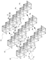
- the honeycomb structure rows 30 can be arranged between the tetracube structure rows 10 arranged in a plurality of rows.
- the honeycomb structure row 30 is formed with a plurality of honeycomb concave portions 35 having parallel edges 33 arranged in parallel to each other at the opening edge on both sides, and the honeycomb concave portions 35 are arranged in a first direction orthogonal to the parallel edges 33.
- the two inclined surfaces 31 that extend inward from the parallel edges 33 and incline downward toward the center are connected to the inner sides of the two parallel edges 33 facing each other.
- the opposite parallel edges 33 of the opening edges of the honeycomb recesses 35 on the opposite surface are formed, and on both sides of the two inclined surfaces 31, the opposing side edges are connected by connecting pieces 32 formed of two triangular surfaces 32X.
- a honeycomb recess 35 having six surfaces can be formed by the two inclined surfaces 32 and the connecting piece 31.
- the two triangular faces 32X constituting the connecting piece 31 are connected to each other via one boundary line 32b which is the outer peripheral edge, the other boundary line 32c is connected to the side edge of the two inclined surfaces 31, and the other
- the boundary line 32 a and the parallel edge 33 can constitute the opening edge of the honeycomb recess 35.
- This tetracube structure is obtained by connecting the connecting pieces 32 of the honeycomb structure row 30 to the tetracube 1 of the tetracube structure row 10 at the boundary between the tetracube structure row 10 and the honeycomb structure row 30 adjacent to each other.
- the row 10 and the honeycomb structure row 30 can be connected.
- the above tetra-cube structure has a beautiful appearance by making use of the advantages of the tetra-cube structure row and the honeycomb structure row by arranging and connecting the honeycomb structure rows between the tetra-cube structure rows arranged in a plurality of rows. Excellent functionality can be demonstrated.
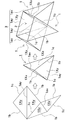
- the tetracube structure of the present invention includes a first tetracube structure 21 and a second tetracube structure 22, and the first tetracube structure 21 and the second tetracube structure 22 are angled. It can be connected in a certain state.
- the first tetracube structure 21 is connected to the first tetracube structure 21 and the second tetracube structure 22 are connected to each other.
- a connecting piece 6 provided continuously to the boundary line 1c is provided, and this connecting piece 6 is connected to the tetracube 1 of the second tetracube structure 22 so that the first tetracube structure 21 and the second tetracube structure 21 The tetracube structure 22 can be connected.
- the above tetracube structure can easily and securely connect the first tetracube structure and the second tetracube structure via the connecting piece, and can also clean the appearance of the connecting part. There are also features.
- the surface material 18 can be connected to the surface of the tetracube structure of the present invention.
- the tetracube structure described above can provide a closed space in the interior while further increasing the compressive strength by adhering a surface material to the surface.
- the above tetracube structure supports the surface material in a line shape at the square opening edge which is the opening edge of the quadrangular pyramidal recess formed by the adjacent tetracubes, and the support force is concentrated locally. There is a feature that can be surely prevented.
- the tetracube structure of the present invention has a support 17, activated carbon, moisture absorbent, deodorant, fragrance, insecticide, mortar, clay, inorganic filler, between the surface material 18 and the quadrangular pyramid recess 2. Any one or more of flame retardants, digestive agents, fertilizers, seeds can be placed.
- the above tetracube structure is made of a support, activated carbon, hygroscopic agent, deodorant, fragrance, mortar, clay, inorganic filler, flame retardant, digestive agent, fertilizer, seed, or more as a surface material. These functions can be effectively exhibited by arranging them in a space between the quadrangular pyramid-shaped recesses.
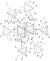
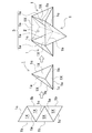
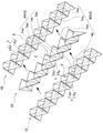
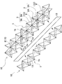
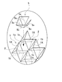
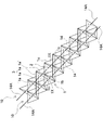
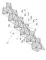
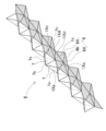
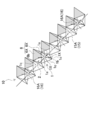
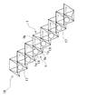
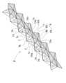
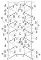
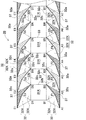
- FIG. 1 It is a perspective view of the tetra-cube structure concerning one example of the present invention. It is the perspective view which looked at the tetra-cube structure shown in FIG. 1 from a different angle. It is a disassembled perspective view which shows the connection structure of the several tetracube which comprises the tetracube structure shown in FIG. It is a disassembled perspective view which shows the state which connects the tetra-cube structure row
- seat which connects the tetra-cube structure row
- top view which shows another example of the connection sheet
- perspective view of the tetra-cube structure concerning other examples of the present invention.
- side view which shows the state which curves the tetra-cube structure shown in FIG.
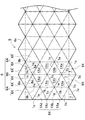
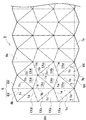
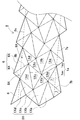
- an expanded view which shows an example of the pattern sheet which manufactures the tetra-cube structure row
- FIG. 36 is a development view showing an example of a pattern sheet for manufacturing the honeycomb structure row shown in FIG. 35. It is an expanded view which shows another example of the pattern sheet which manufactures a honeycomb structure row
- FIG. 38 is a perspective view showing a honeycomb structure row manufactured by the pattern sheet shown in FIG. 37. It is a disassembled perspective view of the tetra-cube structure concerning the other Example of this invention. It is sectional drawing of the tetra-cube structure concerning the other Example of this invention.
- the tetra-cube structure of the present invention is used as a panel for buildings, vehicles, roads, etc., or used as a core material or surface material for walls, floors, ceilings, partitions, etc. of buildings, or is also a closed space inside. It is used as a core material for panels and protectors having various structures, and as a core material for various structures.
- the structure of the tetracube structure of the present invention will be described in detail.
- the square opening edge 3 is formed by a plurality of intersecting first and second ridge lines 4A and 4B.
- the square opening edge 3 is formed by the third ridgeline 4C and the fourth ridgeline 4D.
- the first ridge line 4A of the first surface 11 and the third ridge line 4C of the second surface 12 are parallel to each other, and in plan view, the first ridge line 4A is intermediate between the adjacent third ridge lines 4C. And the third ridgeline 4C is disposed so as to be positioned between the adjacent first ridgelines 4A.
- the second ridge line 4B of the first surface 11 and the fourth ridge line 4D of the second surface 12 are parallel to each other, and the second ridge line 4B is adjacent to each other in the plan view. And the fourth ridge line 4D is disposed so as to be positioned between the adjacent second ridge lines 4B.
- the square opening edge 3 of the first surface 11 is located at the opening edge of the quadrangular pyramid-shaped recess 2 extending from the first surface 11 toward the second surface 12.
- the vertex is located at the intersection of the ridgeline 4 of the second surface 12.
- the square opening edge 3 of the second surface 12 is located at the opening edge of the quadrangular pyramid-shaped recess 2 extending from the second surface 12 toward the first surface 11.
- the vertex is located at the intersection of the ridgeline 4 of the first surface 11.
- the tetra-cube structure shown in FIGS. 1 and 2 is formed into a plate shape having a predetermined thickness, and a plurality of quadrangular pyramid-shaped concave portions 2 having an opening edge as a square opening edge 3 are vertically and horizontally formed on both sides thereof. Are arranged.
- the quadrangular pyramid-shaped recess 2 formed on the first surface 11 side of the tetracube structure has the quadrangular pyramid extending toward the second surface 12 while positioning the square opening edge 3 on the first surface 11.
- the apex is arranged on the second surface 12 as a shape, and the quadrangular pyramid-shaped recess 3 formed on the second surface 12 side positions the square opening edge 3 on the second surface 12 and the first surface.
- the apex is arranged on the first surface 11 as a quadrangular pyramid extending toward the side 11.
- adjacent quadrangular pyramid-shaped recesses 2 are connected so as to share an opening line 1 a constituting one side of the square opening edge 3.
- Each quadrangular pyramid-shaped recess 2 is formed by four triangular surfaces 1X extending inwardly from the square opening edge 3, as shown in FIG.
- the virtual quadrangular pyramid-shaped concave portion 2 formed by the four triangular surfaces 1 ⁇ / b> X is indicated by a bold line.
- the triangular surface 1X has one side as the opening line 1a constituting the square opening edge 3, and the other two sides as the boundary lines 1b and 1c of the adjacent triangular surface 1X.
- the four triangular surfaces 1X are connected by opposing boundary lines 1b and 1c having the same length to form a quadrangular pyramid-shaped recess 2 and a square opening edge 3 by four opening lines 1a. .
- the tetracube structure has two triangular surfaces 1X located on both sides of the first ridge line 4A of the first surface 11 and two surfaces located on both sides of the fourth ridge line 4D of the second surface 12. Are connected to each other by boundary lines 1b and 1c to form a tetracube 1, and two triangular faces 1X located on both sides of the second ridge line 4B of the first surface 11 and the second surface Tetracube 1 is formed by connecting two triangular faces 1X located on both sides of twelve third ridgelines 4C with boundary lines 1b and 1c.
- the first direction is the extension direction of one of the two diagonal lines of the square opening edge 3 (the x-axis direction in FIGS. 1 and 2)
- the second direction is in the horizontal plane.
- the direction is perpendicular to the first direction (the y-axis direction in FIGS. 1 and 2).
- the plurality of tetracubes 1 are connected in a first direction to a plurality of rows of tetracubes arranged in a line by connecting the adjacent tetracubes 1 with a boundary line 1 b facing each other.
- tetracube structure column 10 It consists of a cube structure column 10.
- adjacent tetracube structure rows 10 are connected by a boundary line 1c facing each other, and a plurality of tetracube structure rows 10 are connected in the second direction.
- the second direction orthogonal to the first direction which is one diagonal direction of the square opening edge 3 is a square. It becomes the other diagonal direction of the opening edge 3.
- the second direction orthogonal to the first direction which is one diagonal direction of the square opening edge is not necessarily the other diagonal line of the square opening edge. Does not match the direction.
- the above tetracube structure is divided into a plurality of tetracube structure rows 10 as shown in FIGS. 4 to 6, and the plurality of tetracube structure rows 10 are arranged on the side including the opposing boundary line 1c.
- a multi-cube tetracube structure is formed by connecting to each other at the edges or side surfaces.
- Each tetra-cube structure row 10 is formed by processing a sheet material or a plate material made of paper, plastic, metal plate, or nonwoven fabric into a predetermined three-dimensional shape.
- the structure in which the tetracube structure is constituted by a plurality of rows of tetracube structures 10 can be produced in large quantities and processed into a plate shape having a predetermined width by connecting them. .
- the tetra-cube structure row 10 shown in FIGS. 4 to 6 connects a plurality of tetra-cubes 1 in a line.
- the tetracube 1 is a tetrahedron composed of four triangular faces 1X.
- a tetracube 1 that is a tetrahedron is positioned up and down in FIGS. 1 to 3, two opening lines 1 a forming a square opening edge 3 of the first surface 11 and the second surface 12, and FIG. 4.
- FIG. 3 As shown in FIG.
- the connecting portion that connects the cube structure rows 10 includes two boundary lines 1c that connect the tetracubes 1 adjacent in the second direction (y-axis direction in the drawing).
- two opening lines 1a are arranged at upper and lower twist positions
- two boundary lines 1b are arranged at front and rear twist positions
- two boundary lines 1c are arranged at left and right twist positions. Is arranged.
- the vertical direction means the thickness direction (z-axis direction in the figure) of the tetracube structure
- the front-back direction is a first direction that is one diagonal direction of the square opening edge 3 ( In the figure, it means the x-axis direction)
- the left-right direction means the second direction (y-axis direction in the figure) perpendicular to the first direction in the horizontal plane.
- the tetracube structure row 10 shown in FIGS. 4 to 6 arranges tetracubes 1 adjacent to each other in an upside down posture and connects opposing boundary lines 1b to form a linear shape as a whole.
- the plurality of tetracubes 1 connected in a straight line are connected so that the opening lines 1a adjacent to each other are connected in a zigzag pattern in the same plane.
- the tetracube 1 is formed by connecting four triangular faces 1X at the outer peripheral edge to form a tetrahedron.
- the tetra-cube 1 composed of four triangular surfaces 1X includes an opening line 1a serving as a square opening edge 3 as a first side of the triangular surface 1X, and a boundary line 1b between the tetra-cube 1 adjacent in the front-rear direction as a triangular surface.
- the boundary line 1c with the tetracube 1 adjacent in the left-right direction is configured with the third side of the triangular surface 1X.
- the four triangular surfaces 1X have sides of equal length, that is, the first sides are connected to each other, the second sides are connected to each other, and the third sides are connected to each other.
- a tetrahedron is formed.
- the tetracube 1 is formed by connecting four congruent triangular surfaces 1X to each other as shown in FIGS. 7 to 10 to form a tetrahedron, or as shown in FIG. They are connected to each other to form a tetrahedron.
- the tetracube 1 composed of two sets of congruent triangular surfaces has one set of triangular surfaces as acute triangles and the other set of triangular surfaces as obtuse triangles, or not shown.
- One set of triangular surfaces can be acute triangles, the other set of triangular surfaces can be right triangles, or two sets of triangular surfaces can be acute triangles.
- a tetracube structure formed by connecting a plurality of rows of tetracube structures 10 has a quadrangular pyramid-shaped recess 2 formed by four tetracubes 1 adjacent to the front, rear, left and right. Forming.
- the four tetracubes 1 arranged in the front-rear and left-right directions and adjacent to each other are connected to each other by the boundary line 1b and the boundary line 1c facing each other, and the four triangular faces 1X facing each other form a quadrangular pyramid-shaped recess 2.
- the square opening edge 3 is formed by four opening lines 1a located at the opening edge.
- the above tetracube structure adjusts the ratio of the lengths of the first side, the second side, and the third side of the four triangular surfaces 1X constituting the tetracube 1 to form the quadrangular pyramid-shaped recess 2. And the shape of the square opening edge 3 can be variously changed, and the thickness of the tetracube structure relative to one side of the square opening edge 3 can be adjusted.
- the tetracube 1 shown in FIGS. 1 to 7 forms a regular tetrahedron with four congruent triangular surfaces 1X as regular triangles.
- the tetra-cube structure formed by connecting the tetra-cube structure row 10 having the tetra-cube 1 as a regular tetrahedron has a quadrangular pyramid-shaped recess 2 as a pyramid-shaped regular quadrangular pyramid obtained by dividing the regular octahedron into two.
- the square opening edge 3 is a square.
- the tetra-cube structure having this structure can realize excellent strength by making a large number of tetra-cubes 1 and quadrangular pyramid-shaped recesses 2 formed by these tetra-cubes 1 into stable shapes.
- this tetracube structure is composed of a regular tetrahedral tetracube 1 and a pyramid-shaped quadrangular pyramid-shaped recess 2 which is a regular tetragonal pyramid.
- a geometrically beautiful appearance in which the opening edges 3 are regularly arranged an excellent design can be realized.
- the four congruent triangular planes 1X are isosceles triangles having the same lengths of the second side and the third side as the boundary lines 1b and 1c.
- a tetra-cube structure formed by connecting the tetra-cube structure rows 10 composed of the tetra-cubes 1 has a regular quadrangular pyramid shape with four opposing triangular surfaces 1X of four tetra-cubes 1 adjacent to the front, rear, left and right.
- the recess 2 is formed, and the square opening edge 3 is a square.
- the tetracube structure of this structure can also form a regular quadrangular pyramid-shaped concave portion 2 with a large number of tetracubes 1 to realize excellent strength, and a large number of isosceles triangular triangular surfaces 1X and square square opening edges 3 Can be a beautifully arranged geometrically arranged appearance.
- the tetracube 1 shown in FIG. 8 has a first side that constitutes an opening line 1a as a triangular surface 1X that is an isosceles triangle, the second side and the third side that have the same length constituting the boundary lines 1b and 1c. It is longer than the side. As shown in FIG.
- the tetracube structure formed of the tetracube 1 has a thickness of the tetracube structure by increasing the depth of the quadrangular pyramid-shaped recess 2 with respect to one side of the square opening edge 3. Can be thickened. However, in the tetracube structure, the second side and the third side of the triangular surface that is an isosceles triangle can be made shorter than the first side.
- This tetracube structure has a quadrangular pyramid-shaped concave portion shown in FIG. 7 with the depth of the quadrangular pyramid-shaped concave portion with respect to one side of the square-opening edge, with the quadrangular pyramid-shaped concave portion as a regular quadrangular pyramid
- the tetracube structure can be made thinner than 2.
- the second side or the third side serving as the boundary line and the first side serving as the opening line can be made equal.
- the third side that is the boundary line 1c is equal to the first side that is the opening line 1a.
- the tetra-cube structure formed by connecting the tetra-cube structure rows composed of the tetra-cubes 1 is a quadrangular pyramid-shaped recess formed by the four triangular faces 1X facing each other of the four tetra-cubes 1 adjacent to each other in the front, rear, left and right directions.
- the tetracube structure of this structure is also a geometrical structure in which a large number of rhombic square opening edges 3 are regularly arranged while forming a quadrangular pyramid-shaped recess 2 with a large number of tetracubes 1 to achieve excellent strength. A beautiful appearance can be achieved.
- the four congruent triangular surfaces 1X are acute triangles having different lengths of the first side, the second side, and the third side.
- the tetracube structure formed by connecting the tetracube structure rows composed of the tetracubes 1 connects the adjacent tetracubes 1 with the same boundary lines 1b and with the boundary lines 1c.
- a quadrangular pyramid-shaped recess 2 is formed by four opposing triangular surfaces 1X of four tetracubes 1 adjacent in the front, rear, left, and right, and the square opening edge 3 has a rhombus shape.
- the tetracube structure of this structure is also a geometrical structure in which a large number of rhombic square opening edges 3 are regularly arranged while forming a quadrangular pyramid-shaped recess 2 with a large number of tetracubes 1 to achieve excellent strength. A beautiful appearance can be achieved.
- the tetracube 1 shown in FIG. 11 has two sets of congruent triangular faces 1Xx and 1Xy connected to each other to form a tetrahedron.
- the tetracube 1 shown in FIG. 11 has two sets of congruent triangular surfaces 1Xx and 1Xy, each having two sets of two sides having the same length of the second side and the third side and different lengths of the first side. It is an isosceles triangle.
- two sets of congruent triangular surfaces 1Xx and 1Xy have one as an acute triangle and the other as an obtuse triangle.
- the tetracube 1 connects the first sides of the congruent triangles to each other, and connects the opposing second and third sides of the obtuse and acute triangles to form a tetrahedron.
- the tetra-cube structure row 10 constituted by the tetra-cubes 1 is formed by connecting the tetra-cubes 1 adjacent to each other in the front-rear direction by a boundary line 1b facing each other, and forming a short first side.
- the line 1ax and the opening line 1ay having the long first side are arranged in a zigzag shape.
- a plurality of rows of tetracube structures 10 are connected by a border line 1c facing each other between the tetracubes 1 adjacent to each other in the left-right direction, and the opening lines 1ax formed of the short first sides are straightened on both upper and lower surfaces.
- a first ridge line 4A and a third ridge line 4C connected in a shape, and a second ridge line 4B and a fourth ridge line formed by linearly connecting the opening lines 1ay including the long first sides. 4D is formed.
- a quadrangular pyramid-shaped recess 2 is formed by four opposing triangular surfaces 1Xx and 1Xy of four tetracubes 1 adjacent to each other in the front, rear, left and right directions.
- the two triangular faces 1Xx and 1Xy that face each other are congruent isosceles triangles, so that the square openings formed by the two sets of opening lines 1ax and 1ay that face each other.
- Edge 3 is rectangular. That is, in this tetracube structure, the short opening line 1ax and the long opening line 1ay connected in a zigzag manner at the opening edge of the quadrangular pyramid-shaped recess 2 are connected in an orthogonal posture.
- the tetracube structure of this structure also has a geometrical structure in which a large number of rectangular opening edges 3 are regularly arranged while realizing excellent strength by forming a quadrangular pyramid-shaped recess 2 with a large number of tetracubes 1. A beautiful appearance can be achieved.
- the tetracube structure row 10 composed of tetracubes 1 formed by connecting two sets of congruent triangular faces 1Xx and 1Xy shown in FIG. 11 are adjacent to each other as shown in FIGS. It is also possible to connect a plurality of tetracubes 1 so that the arranged tetracube structure rows 10 are arranged symmetrically in the left-right direction (second direction). In this way, the tetracube structure in which the tetracube structure rows 10 adjacent to each other are arranged in a line symmetrical manner also connects the opposing boundary lines 1c between the tetracubes 1 adjacent in the left-right direction to form a plurality of rows of tetracubes.
- This tetracube structure also forms a quadrangular pyramid-shaped recess 2 with four triangular faces 1Xx, 1Xy facing each other of four tetracubes 1 adjacent to each other in the front, rear, left, and right, but two sets of triangular faces 1Xx, 1Xy are lines. Since they are arranged symmetrically, the square opening edge 3 formed by two sets of adjacent opening lines 1ax, 1ay is formed in a bowl shape (a quadrangle having two diagonal lines in a cross shape).
- the tetra-cube structure of this structure is also arranged in a symmetrical manner with a large number of bowl-shaped square opening edges 3 while forming a quadrangular pyramid-shaped recess 2 with a large number of tetra-cubes 1 and realizing excellent strength. A beautiful geometric appearance.
- the first surface 11 and the second surface 12 have a short first.
- the ridgeline 4 is formed by alternately connecting the opening line 1ax composed of the sides and the opening line 1ay composed of the long first side. At this time, since the short opening line 1ax and the long opening line 1ay are not connected in a straight line shape but are connected in a zigzag shape, the ridge line 4 is not a complete straight line.
- each ridge line 4 in which the short opening line 1ax and the long opening line 1ay are connected in a zigzag shape is arranged in a substantially straight line in one direction as a whole, and the ridge lines 4 arranged in the same direction. Are arranged substantially in parallel without crossing each other. Therefore, in the tetracube structure of the present invention, each ridge line does not necessarily have to be linear, and the opening lines of the square opening edges constituting each ridge line are connected in a zigzag shape so as to be substantially linear. It is also possible to arrange substantially linear ridge lines extending in the same direction so as not to cross each other.
- the tetra-cube structure can be provided with a partition wall 8 inside the quadrangular pyramid-shaped recess 2.
- the quadrangular pyramid-shaped recess 2 in the figure has a partition wall 8 provided at one diagonal line of the square opening edge 3, and the two boundary lines 8 c of the partition wall 8 are defined as the boundary lines of the quadrangular pyramid-shaped recess 2. It is connected to 1c.
- the partition wall 8 divides the inside of the quadrangular pyramid-shaped recess 2 into two triangular pyramid-shaped recesses 2A, and the two opening lines 1a of the square opening edge 3 and the opening line 8a of the partition wall 8 Thus, the triangular opening edge 3A is formed.
- a large number of triangular opening edges 3 ⁇ / b> A are regularly arranged while reinforcing the quadrangular pyramid-shaped recess 2 with the partition wall 8.
- a beautiful geometric appearance can be achieved.
- a triangular pyramid-shaped recess opening 2A divided into two by the partition wall 8 is an isosceles triangle, and a large number of isosceles triangular openings. It is possible to obtain a geometrically beautiful appearance in which the edges 3A are regularly arranged.
- the quadrangular pyramid-shaped concave portion 2 having the square opening edge 3 as a rhombus is divided by providing a partition wall 8 at the position of the shorter diagonal line of the two diagonal lines of the rhombus square opening edge 3.
- the triangular opening edge 3 ⁇ / b> A is an acute-angled triangle, so that more excellent strength can be realized.
- the shape of the triangular surface 1X constituting the tetra-cube 1 is set so that the lengths of the first side, the second side, and the third side are as follows.
- the shape of the square opening edge 3 that is a rhombus is a rhombus formed by connecting two regular triangles, and the shape of the partition wall 8 can be a regular triangle.
- This tetra-cube structure has a geometry in which a large number of regular triangular triangular opening edges 3A are regularly arranged with a partition wall 8 and two triangular opening edges 3A divided into two by the partition wall 8 as congruent regular triangles. A beautifully aesthetic appearance.
- the shape of the triangular surface 1X constituting the tetracube 1 is an isosceles triangle in which the lengths of the first side, the second side, and the third side have the following ratios:
- the shape of the square opening edge 3 that is a rhombus can be a rhombus formed by connecting two regular triangles.
- the partition wall 8 that divides the quadrangular pyramid-shaped concave portion 2 into two is a right-angled isosceles triangle having the same boundary line 8c length, and the triangular opening edge 3A divided into two by the partition wall 8 is a regular As a triangle, a geometrically beautiful appearance in which a large number of regular triangular triangular opening edges 3A are regularly arranged can be obtained.
- the plurality of tetracube structure rows 10 are arranged in such a manner that the side edges face each other, and the boundary lines 1 c that face each other are connected to each other. Concatenated in multiple rows. Tetracube structure rows 10 adjacent to each other are connected to each other with a predetermined pitch or without shifting their positions so that the boundary lines 1c connected to each other face each other.
- the tetracube structure row 10 shown in FIGS. 4 to 6 is connected with a half-pitch shift
- the tetracube structure row 10 shown in FIG. 12 is connected with a predetermined pitch shift
- the tetracube structure row 10 shown in FIG. Connected without shifting the position.
- the plurality of tetracube structure rows 10 arranged and connected so that the boundary lines 1c connected to each other face each other are zigzag-shaped on the first surface 11 and the second surface 12.
- a square opening edge 3 is formed by connecting the opening lines 1a.
- the plurality of tetracube structure rows 10 are provided with connecting pieces 6 along the boundary line 1 c and are connected to each other via the connecting pieces 6. be able to.
- the tetra-cube structure row 10 shown in FIGS. 4, 5, 12, and 13 is provided with connecting pieces 6 along one side edge, and the tetra-cube structures adjacent to each other through the connecting pieces 6.
- the columns 10 are connected to each other.
- the tetra-cube structure row 10 shown in the figure is provided with a connecting piece 6 that is continuous with a boundary line 1c located on one side edge, and the adjacent tetra-cube structure row 10 with the back side of the connecting piece 6 as an adhesive surface. Are adhered to the surface side of the opposing triangular surface 1X.
- the shape of the connecting piece 6 is formed by connecting two triangular faces 6X, and the triangular face 6X constituting the connecting piece 6;
- the triangular surface 1X of the tetracube 1 facing this is a congruent triangle.
- two triangular surfaces 6 ⁇ / b> X of the connecting piece 6 are valley-folded along a bend line 6 b serving as a boundary, the two triangular surfaces 6 ⁇ / b> X constituting the connecting piece 6, and these triangles
- a quadrangular pyramid-shaped recess 2 is formed by the two triangular surfaces 1X of the tetracube 1 facing the surface 6X.
- the connecting piece 6 shown in the figure is formed by valley-folding the two triangular surfaces 6X along the folding line 6b, so that the back side surface serving as the bonding surface becomes the bonding surface on the adjacent tetracube structure row 10 side.
- the shape is along the surface of the triangular surface 1X.
- the connecting piece 6 of one tetracube structure row 10 is bonded as a shape along the opposing triangular surface 1X of the adjacent tetracube structure row 10, so that the position of the connecting piece 6 is accurately specified, It has the feature that it can be firmly bonded in a wide area and has a beautiful appearance.
- the shape of the connecting piece does not necessarily need to be a shape along the opposing triangular surface, and the tip portion can be cut as will be described later.
- the connecting piece 6 is further enlarged.
- the connecting piece 6 shown in FIG. 5 straddles the opposing triangular surface 1X of the adjacent tetracube structure rows 10 and the opposite triangular surface 1X formed by connecting the triangular surface 1X with the opening line 1a interposed therebetween. It is structured to adhere.
- the connecting piece 6 shown in the figure has a first connecting piece 6A bonded to the opposing triangular surface 1X of the adjacent tetracube structure row 10 and an opposite triangular surface 1X connected to these triangular surfaces 1X. And a second connecting piece 6B to be bonded.
- the connecting piece 6 in FIG. 5 has the shape of the first connecting piece 6A formed by connecting two triangular surfaces 6X, and the first connecting piece 6A is connected along the boundary 1c of the tetracube 1.
- the shape of the second connecting piece 6B is formed by connecting the two triangular surfaces 6X, and the second connecting piece 6B is connected along the outer edge of the first connecting piece 6A adjacent to each other. is doing.
- the first connecting piece 6A has two triangular surfaces 6X that are congruent with the triangular surface 1X of the tetracube 1 that faces the two triangular surfaces 6X, and is symmetrical with respect to the bending line 6b that is the boundary.
- the folded line 6b is valley-folded, and the two triangular surfaces 6X and the two triangular surfaces 1X of the opposing tetracube 1 form a quadrangular pyramid-shaped recess 2.
- the 2nd connection piece 6B is arrange
- the second connecting piece 6B connects one triangular surface 6X to one opposing first connecting piece 6A via a bent line 6a and the other triangular surface 6X via a bent line 6a. Are connected to the other opposing first connecting piece 6A.
- the folding line 6b is folded at a valley.
- the above connecting pieces 6 are mountain-folded at a folding line 6a that is a boundary line between the first connecting piece 6A and the second connecting piece 6B, and are connected to each other via the bent line 6a.
- a folding line 6a that is a boundary line between the first connecting piece 6A and the second connecting piece 6B
- the opposing triangular surface 1X of the adjacent tetracube structure row 10 and the opposite triangular surface 1X are straddled. Are attached.
- the connecting piece 6 of the tetracube structure row 10 is connected over the opposite triangular surface 1X in addition to the opposing triangular surface 1X of the adjacent tetracube structure row 10, so that the bent line of the connecting piece 6 is bent.
- this connection piece also does not necessarily need to make the shape of the 1st connection piece or the 2nd connection piece into the shape which follows the opposing triangular surface.
- the connecting piece 6 can also cut the tip of the second connecting piece 6 ⁇ / b> B with a cut line 6 s.
- the tetracube structure rows 10 described above connect the tetracube structure rows 10 adjacent to each other via the connecting pieces 6, but the plurality of tetracube structure rows 10 are provided with connecting pieces along the boundary line. Instead, as shown in FIG. 16, it can also connect via the connection plate 13 arrange
- the connecting plate 13 shown in the figure is a belt-like plate facing the side surface including the boundary line 1c of the tetracube structure row 10.
- the boundary lines 1c of the opposing tetracubes 1 are bonded to both surfaces of a connection plate 13 disposed between adjacent tetracube structure rows 10, and a plurality of tetracube structure rows 10 are connected.
- the tetra-cube structure row 10 is formed by applying an adhesive to the boundary line 1c serving as an adhesive portion and bonding it to the opposing connecting plate 13 in this state, or in a state where the boundary line 1c is in close contact with the connecting plate 13 An adhesive can be applied and adhered along the line 1c.
- the connecting plate 13 disposed between the boundary lines 1c facing each other is also used as a partition wall 8 that divides the quadrangular pyramid-shaped recess 2 into two.
- the connecting plate 13 serving as the partition wall 8 divides the quadrangular pyramid-shaped concave portion 2 into two triangular pyramid-shaped concave portions 2 ⁇ / b> A on the first surface 11 and the second surface 12.
- adjacent tetracube structure rows 10 are connected by a connecting plate 13, and the connecting plate 13 is also used as a partition wall 8 to divide the quadrangular pyramid-shaped concave portions 2 on both sides into triangular pyramid-shaped concave portions 2A.
- the plurality of rows of tetracube structures 10 can be connected by bonding the boundary lines 1c facing each other.
- an adhesive is applied to the boundary line 1c serving as the bonding portion, and the boundary lines 1c facing each other in this state are adhered to each other, or the boundary lines 1c are adhered to each other. In this state, an adhesive can be applied and bonded along the boundary line 1c.
- the plurality of tetracube structure rows 10 can connect the mutually facing triangular surfaces 1X via a connecting sheet, or after bonding the boundary line with an adhesive, the opposing triangular surfaces 1X can be connected by a connecting sheet. It can also be linked.
- FIG. 17 shows an example of the connecting sheet 5.
- the connecting sheet 5 shown in the figure is an adhesive tape having an adhesive surface on one surface.
- the triangular surfaces 1X facing each other are bonded together by an adhesive surface, and the opposing boundary lines 1c are connected to each other.
- the connection sheet 5 shown in FIG. 17 has a structure in which four triangular surfaces 1X forming one quadrangular pyramid-shaped recess 2 are connected.
- the connecting sheet 5 in the figure is folded at a folding line 5c, and the adjacent triangular surface 1X is bonded via an adhesive surface provided on the back surface side in the drawing.
- the connecting sheet 5 is formed as a single sheet formed by connecting a plurality of bonding surfaces with folding lines 5c, and is bent at the folding lines 5c to bend and bond the boundary lines 1c facing each other. Connect by plane.
- the shape of each bonding surface is a triangle congruent with the triangular surface 1X bonded to each other.
- the connection sheet can be bonded only in the vicinity of the boundary line to be bonded to each other without bonding the entire triangular surface.
- This connection sheet can cut the connection sheet 5 with the cut line 5s as shown with the dashed-dotted line of a figure, and can reduce the usage-amount of an adhesive tape.
- the connecting sheet can also connect the triangular faces facing each other individually as an adhesive tape that connects only one boundary line.
- the connecting sheet 5 may be structured to connect three or more adjacent tetracube structure rows 10.
- the connecting sheet 5 shown in FIG. 18 is bonded across a plurality of adjacent tetracube structure rows 10 to bond the triangular surfaces 1X constituting the boundary line 1c facing each other.
- the connecting sheet 5 in the figure is formed as a single sheet formed by connecting a plurality of adhesive surfaces by bending lines 5a and 5c, and is folded at a folding line 5c indicated by a one-dot chain line and indicated by a two-dot chain line.
- the triangular surface 1X which opposes with the adhesion surface provided in the back surface side in the figure is adhere
- the connecting sheet 5 is repeatedly bent and folded in the folding lines 5a and 5c so that the folded line 5a faces the opening line 1a and is folded in the valley.
- the curved line 5c is bonded in a state of facing the boundary line 1c, and a plurality of tetracube structure columns 10 are connected by the boundary line 1c.
- connection sheet 5 As described above, the structure for connecting the plurality of tetracube structure rows 10 via the connection sheet 5 is not shown, but the connection sheet is bonded to both the first surface side and the second surface side, A plurality of tetracube structure rows can be connected more firmly.
- the tetra-cube structure shown in FIGS. 1 and 2 has a large number of tetra-cube structure rows 10 connected in a planar shape, and a plurality of quadrangular pyramid-shaped recesses 2 are arranged side by side on both sides of the ridge line 4 to form a first A large number of quadrangular pyramid-shaped recesses 2 are continuously provided on both the surface 11 and the second surface 12.
- This tetracube structure can be used for various applications as a whole in the form of one panel.
- the tetracube structure of the present invention can be formed into a strip shape by connecting two to several tetracube structure rows.
- the tetracube structure can be used in a posture in which the entire structure is curved.
- the curved tetracube structure can be placed on an object having a curved surface as the surface or inner surface, and can be brought into close contact with the surface or inner surface.
- a tetracube structure having a curved shape as a whole is laminated on the surface of a protector whose inner surface is a curved surface, or used as a core material of a protector, or a cylindrical column or corner, for example.
- this tetracube structure can also be made into a ring shape by connecting both ends as shown by arrows in FIG.
- the above-described tetracube structure row 10 is formed by processing a sheet material or a plate material made of paper, plastic, metal plate, or nonwoven fabric into a predetermined three-dimensional shape.
- the tetra-cube structure row 10 is formed into a predetermined three-dimensional shape by bending and bonding after cutting the above sheet material or plate material into a predetermined pattern.
- the pattern sheet made of paper, plastic, and metal plate is made of a material and thickness that can be bent freely in the folding line.
- As the pattern sheet made of a nonwoven fabric a sheet is used that is obtained by applying or spraying a binder to the nonwoven fabric or curing the nonwoven fabric immersed in a liquid containing the binder.
- a pattern sheet made of any one of paper, plastic, metal plate, and nonwoven fabric can be used alone, but a pattern sheet made of different materials can be laminated in multiple layers.
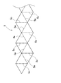
- FIGS. 21 shows the pattern sheet 9 of the tetracube structure row 10 shown in FIG. 4
- FIG. 22 shows the pattern sheet 9 of the tetracube structure row 10 shown in FIG. 5
- FIG. 23 shows the tetracube structure row shown in FIG. Ten pattern sheets 9 are shown.
- FIG. 24 shows a pattern sheet 9 of a tetracube structure row composed of tetracubes 1 shown in FIG. 8
- FIG. 25 shows a pattern sheet 9 of a tetracube structure row composed of tetracubes 1 shown in FIG.
- FIG. 26 shows the pattern sheet 9 of the tetracube structure row composed of the tetracube 1 shown in FIG. 10
- FIG. 27 shows the pattern sheet 9 of the tetracube structure row 10 shown in FIG. 12, and
- column 10 is each shown.
- the pattern sheet 9 shown in these drawings has a planar shape in which a large number of triangular surfaces 1X constituting the continuous tetracube 1 are connected at the outer peripheral edges serving as the opening lines 1a and the boundary lines 1b and 1c.
- the pattern sheet 9 is bent at the outer peripheral edge of each triangular surface 1X, and the opposing triangular surfaces 1X are connected by equal length sides to form a tetracube 1 composed of four triangular surfaces 1X.
- the pattern sheet 9 shown in these drawings includes four triangular surfaces 1X forming one tetracube 1 in order to produce a tetracube structure row 10 having a shape formed by connecting a plurality of tetracubes 1.
- the sides that become the opening line 1a and the sides that become the boundary line 1c are connected to form a triangular surface block 9X arranged in a row, and a plurality of rows of triangular surface blocks 9X are connected to the side that becomes the boundary line 1b. They are connected together to form a sheet.
- Each triangular plane block 9X includes first to fourth triangular planes 1X in order from the bottom in the figure, and these four triangular planes 1X are divided into sides serving as opening lines 1a and sides serving as boundary lines 1c. Are connected alternately.
- the 1st triangular surface 1Xa and the 2nd triangular surface 1Xb are connected in the boundary by the edge
- the first triangular surface 1Xa and the second triangular surface 1Xb that are connected to each other are arranged point-symmetrically so that the outer shape is a parallelogram, and the sides that become the boundary line 1b and the boundary line 1c are formed.
- the sides are arranged so as to be opposite sides of the parallelogram.
- the second triangular surface 1Xb and the third triangular surface 1Xc are connected at the boundary at the side that becomes the boundary line 1c.
- the second triangular surface 1Xb and the third triangular surface 1Xc that are connected to each other are arranged point-symmetrically so that the outer shape is a parallelogram, and the sides that become the opening line 1a and the boundary line 1b are formed. The sides are arranged so as to be opposite sides of the parallelogram.
- the 3rd triangular surface 1Xc and the 4th triangular surface 1Xd are connected by the edge
- each triangular surface 1Xc and the fourth triangular surface 1Xd that are connected to each other are arranged point-symmetrically so that the outer shape thereof is a parallelogram, and the sides that become the boundary line 1b and the boundary line 1c are formed. The sides are arranged so as to be opposite sides of the parallelogram.
- each triangular surface 1X is an equilateral triangle, so that adjacent triangular surfaces 1X are connected at the boundary to form a rhombus.
- the four triangular surfaces 1X constituting the tetracube 1 are congruent triangles.
- the triangular surface block 9X formed by connecting the adjacent triangular surfaces 1X with a point-symmetric posture on the side that becomes the opening line 1a or the side that becomes the boundary line 1c is the boundary between the adjacent triangular surface blocks 9X. That is, the side that becomes the boundary line 1b is connected in a straight line. That is, these pattern sheets 9 can be formed into a shape in which each triangular surface block 9X is linear and a plurality of rows of triangular surface blocks 9X are connected in parallel.
- the pattern sheet 9 having the four triangular planes 1X as congruent triangles is formed by connecting the adjacent triangular plane blocks 9X connected by the side that becomes the boundary line 1b with the side that becomes the boundary line 1b as an axis of symmetry. It has a symmetrical shape. This is because, in a state where a plurality of tetracubes 1 are coupled via the boundary line 1b, the adjacent tetracubes 1 are coupled in a vertically inverted posture.
- the pattern sheet 9 in which the side that becomes the boundary line 1b is linear has a feature that the bending process in this portion can be easily performed.
- the pattern sheets shown in FIGS. 21 to 23 have each triangular surface 1X as a regular triangle, so that in addition to the side that becomes the boundary line 1b, the pattern sheet becomes the opening line 1a that extends over the adjacent triangular surface block 9X.
- the sides and the sides to be the boundary line 1c can also be arranged in a straight line. For this reason, these pattern sheets 9 have the characteristic that the bending process in this part can also be made easy.
- the pattern sheet 9 shown in FIGS. 27 and 28 includes the tetracube 1 composed of two sets of congruent triangular surfaces 1Xx and 1Xy, so that the triangular surface block 9X is composed of two sets of congruent triangular surfaces 1Xx and 1Xy. It consists of four triangular surfaces 1X.
- the first triangular surface 1Xa and the second triangular surface 1Xb are congruent triangles
- the third triangular surface 1Xc and the fourth triangular surface 1Xd are congruent triangles.
- the congruent first triangular surface 1Xa and second triangular surface 1Xb are connected at the boundary at the side that becomes the opening line 1a.
- the first triangular surface 1Xa and the second triangular surface 1Xb that are connected to each other are arranged point-symmetrically so that the outer shape is a parallelogram, and the sides that become the boundary line 1b and the boundary line 1c are formed.
- the sides are arranged so as to be opposite sides of the parallelogram.
- the congruent third triangular surface 1Xc and the fourth triangular surface 1Xd are also connected at the boundary at the side that becomes the opening line 1a.
- the third triangular surface 1Xc and the fourth triangular surface 1Xd that are connected to each other are arranged point-symmetrically so that the outer shape thereof is a parallelogram, and the sides that become the boundary line 1b and the boundary line 1c are formed.
- each triangular surface 1X is an isosceles triangle having the same sides as the boundary line 1b and the boundary line 1c, so the congruent triangular surfaces 1X become the opening line 1a. Connected at the sides to form a rhombus.
- one tetracube structure row 10 is formed by the pattern sheet 9 shown in FIG.
- the other tetracube structure row 10 can be formed by folding the pattern sheet 9 shown in FIG. 28, that is, by bending the mountain fold and the valley fold in reverse.
- the pattern sheet 9 described above is bent in the same direction at the side that becomes the opening line 1a and the side that becomes the boundary line 1c, which are the boundaries of the four triangular planes 1X constituting each triangular plane block 9X (the valley in the figure).
- the length of the four triangular planes 1X facing each other as the side of the boundary line 1b, which is the boundary between adjacent triangular plane blocks 9X, is bent in the opposite direction (mountain fold in the figure).
- the plurality of tetracubes 1 formed by the triangular surface blocks 9X are formed into a shape that is continuous at the boundary line 1b.
- the pattern sheet 9 bends each triangular surface block 9X in the same direction at the side that becomes the opening line 1a and the side that becomes the boundary line 1c (valley fold in the drawing), and the side that becomes the boundary line 1b. Are bent in the opposite direction (mountain folds in the figure), and formed into a three-dimensional tetracube structure array 10 in which a plurality of tetracubes 1 are connected by boundary lines 1b.
- the pattern sheet 9 shown in FIGS. 21 to 28 is a process of bending a triangular surface block 9X composed of four triangular surfaces 1X to form the tetracube 1 and forming triangles located at both ends of the triangular surface block 9X.
- a fixing piece 7 for connecting the surfaces 1X is provided.
- the pattern sheet 9 shown in these drawings is one end edge (lower end edge in the figure) of the triangular surface block 9X, and the fixing piece 7 is integrally formed on the edge that becomes the boundary line 1c of the first triangular surface 1Xa. They are connected.
- the fixing piece 7 is bonded to the inner side surface (front side in the drawing) of the fourth triangular surface 1Xd with the outer side surface (back side in the drawing) as the bonding surface.
- the fixed piece 7 is bonded to the inner surface of the fourth triangular surface 1Xd so that the boundary line 1c of the first triangular surface 1Xa overlaps the boundary line 1c of the fourth triangular surface 1Xd.
- the fixing piece 7 shown in FIGS. 21 to 28 is a triangle congruent with the fourth triangular surface 1Xd to which the fixing piece 7 is bonded.
- the fixing piece 7 having this shape has a feature that it can be firmly bonded in a wide area while being accurately identified by connecting the fixing pieces 7 along the fourth triangular surface 1Xd.
- the fixed piece 7 having a triangle congruent with the fourth triangular surface 1Xd is laminated on the inner surface of the fourth triangular surface 1Xd, and the outer peripheral edge of the fixed piece 7 is used as the inner surface (for example, an opening) of the tetracube 1.
- the fixing piece 7 can be further enlarged to firmly reinforce two or more surfaces of the triangular surface 1X.
- the fixing piece 7 can be further enlarged and bonded not only to the fourth triangular surface 1Xd but also to the third triangular surface 1Xc. This structure can reinforce the tetracube 1 more firmly from the inner surface.
- the fixed piece 7 is positioned on the inner surfaces of the fourth triangular surface 1Xd and the third triangular surface 1Xc, for example, by having a shape and size opposite to the fourth triangular surface 1Xd and the third triangular surface 1Xc.
- the tetracube 1 can be firmly reinforced from the inner surface by bonding.
- the pattern sheet 9 shown in the figure connects the fixed pieces 7 provided on the adjacent triangular surface block 9X with a bending line 7b serving as a boundary.
- a boundary line 1b that is a boundary between adjacent triangular surface blocks 9X and a bent line 7b of the fixed piece 7 are arranged in a straight line, and the adjacent fixed piece 7 is connected to the bent line 7b.
- the shape is axisymmetric with respect to.
- the structure in which the adjacent fixed pieces 7 are integrally connected to each other can easily position the fixed piece 7 and the fourth triangular surface 1Xd by overlapping the bent line 7b on the opposing boundary line 1b.
- the tetracubes 1 connected to each other through the boundary line 1b can be more firmly connected to each other.
- the shape of the fixed piece does not necessarily need to be a shape along the triangular surface to which the fixed piece is bonded, and as shown by a broken line in the figure, the shape of the fixed piece may be a shape formed by cutting the tip portion with a cut line 7s. Since this pattern sheet can reduce the fixed piece, the amount of the sheet material used can be reduced and the cost can be reduced, and the amount of the adhesive material used can be reduced by reducing the bonding area.
- the pattern sheet 9 having the cut line 7s as a straight line has a feature that it can be easily cut while effectively using a sheet material as a raw material.
- the pattern sheet 9 shown in FIGS. 21, 22, and 24 to 28 is provided with a connecting piece 6 for connecting the tetracube structure rows 10 adjacent to each other.
- the connecting piece 6 in these figures has a shape formed by connecting two triangular faces 6X, and each triangular face 6X is the other end edge (upper end edge in the figure) of the triangular face block 9X, Of the triangular surface 1Xd is integrally connected to the edge that becomes the boundary line 1c.
- the two triangular surfaces 6X are connected by a bent line 6b serving as a boundary.
- the connecting piece 6 is bonded to the surface of the opposing triangular surface 1X of the adjacent tetracube structure row 10 with the outer surface (the back surface side in the figure) as the bonding surface.
- the connecting piece 6 is arranged so that the boundary line 1c of the fourth triangular surface 1Xd overlaps the opposing boundary line 1c of the adjacent tetracube structure row 10, and is bonded to the surface of the opposing triangular surface 1X.
- the connecting piece 6 shown in the figure has a triangular shape congruent with the triangular surface 1X to which the connecting piece 6 is bonded.
- the connection piece 6 having this shape is characterized by being able to be firmly bonded in a wide area while being accurately identified as the connection position of the connection piece 6 by being laminated along the opposing triangular surface 1X.
- the boundary line 1b that is the boundary of the adjacent triangular surface block 9X and the bent line 6b of the connecting piece 6 are arranged linearly.
- the adjacent connecting pieces 6 are symmetrical with respect to the bent line 6b.
- the structure in which the adjacent connecting pieces 6 are integrally connected is formed by overlapping the bent line 6b on the boundary line 1b between the opposing triangular surfaces 1X, thereby connecting the connecting pieces 6 and the triangular surface 1X.
- the shape of the connecting piece does not necessarily need to be a shape along the triangular surface to which the connecting piece is bonded, and as shown by a broken line in the figure, it can also be a shape formed by cutting the tip portion with a cut line 6s. Since this pattern sheet can reduce the fixed piece, the amount of the sheet material used can be reduced and the cost can be reduced, and the amount of the adhesive material used can be reduced by reducing the bonding area.
- the pattern sheet 9 having the cut line 6s as a straight line has a feature that it can be easily cut while effectively using a sheet material as a raw material.
- the pattern sheet 9 in FIG. 22 is a pattern sheet 9 for manufacturing the tetracube structure row 10 shown in FIG. 5, and the triangular surface 1X of the adjacent tetracube structure row 10 is opposed to these triangular surfaces 1X.
- a connecting piece 6 is provided that is bonded across the opposite triangular surface 1X that is connected across the opening line 1a.
- the connecting piece 6 in the figure includes the first connecting piece 6A bonded to the opposing triangular surface 1X of the adjacent tetracube structure row 10, and the opposite side formed by connecting to these triangular surfaces 1X.
- a second connecting piece 6B bonded to the triangular surface 1X.
- the first connecting piece 6A has two triangular surfaces 6X, and the boundary line 1c of the fourth triangular surface 1Xd is formed such that the shape of each triangular surface 6X is a triangle congruent with the triangular surface 1X that bonds the triangular surfaces 6X.
- the two triangular surfaces 6X are connected by a bent line 6b as a boundary.
- the second connecting piece 6B has two triangular surfaces 6X, and is arranged in a state in which the opposite outer edges of the adjacent first connecting pieces 6A are connected.
- the second connecting piece 6B connects each triangular surface 6X to the first connecting piece 6A facing each other via a bent line 6a, and is a bent line 6b that serves as a boundary between the two triangular surfaces 6X. It is connected.
- the folding line 6b of the connecting piece 6 is valley-folded so that each triangular surface 6X extends along the opposing triangular surface 1X of the adjacent tetracube structure row 10. Laminated as a shape and bonded.
- the above pattern sheet 9 is bent as follows, and the tetracube structure row 10 is manufactured.
- the pattern sheet 9 shown in FIGS. 21 to 28 is arranged in a predetermined direction along the outer peripheral edge of the adjacent triangular surface 1X, the bending lines 6b and 6a of the connecting piece 6, and the bending line 7b of the fixing piece 7. Bend it.
- the pattern sheet 9 valley-folds the side to be the opening line 1a of the tetracube 1, the side to be the boundary line 1c, and the bent line 6b of the connecting piece 6, and is a boundary line that is a boundary between adjacent triangular surface blocks 9X.
- the side to be 1b and the folding line 7b of the fixed piece 7 are folded in a mountain. Further, with respect to the pattern sheet 9 shown in FIG. 22, the folding line 6a of the connecting piece 6 is folded in a mountain.
- the pattern sheet shown in FIGS. 21 to 28 is for easy understanding of the bending direction of the outer peripheral edge of the triangular surface 1X, the bending lines 6b and 6a of the connecting piece 6, and the bending line 7b of the fixed piece 7.
- the line to be folded is indicated by a one-dot chain line
- the line to be folded is indicated by a two-dot chain line.
- the pattern sheet 9 is bent to form the triangular surface block 9 ⁇ / b> X into the three-dimensional tetracube 1.
- the sides having the same length of each triangular surface 1X overlap each other, that is, the boundary line 1c of the first triangular surface 1Xa overlaps the boundary line 1c of the fourth triangular surface 1Xa, and the first triangle
- the boundary line 1b of the surface 1Xa overlaps with the boundary line 1b of the third triangular surface 1Xa
- the boundary line 1b of the second triangular surface 1Xa overlaps with the boundary line 1b of the fourth triangular surface 1Xa.
- the fixed piece 7 provided at one end of the triangular surface block 9X is wound around the inner surface side of the tetracube 1, and the bent line 7b of the fixed piece 7 is changed to the boundary line 1b of the first triangular surface 1Xa. And the third triangular surface 1Xa so as to overlap the boundary line 1b.
- FIGS. 29 and 30 in order to make it easy to understand the bent state of the pattern sheet 9, the inner surface side of the pattern sheet 9 is displayed in gray and the outer surface side is displayed in white. (3) A fixing piece arranged inside the tetracube is laminated and bonded to the inner surface of the fourth triangular surface 1Xd. In this state, a tetracube structure row 10 is formed in which three-dimensional tetracubes 1 are continuous at the boundary line 1b.
- the pattern sheet 9 having the connecting piece 6 has the bent line 6b of the connecting piece 6 folded at a valley, and the pattern sheet 9 shown in FIG.
- the connecting piece 6 integrally connected to the tetracube 1 is formed into a shape along the opposing triangular surface 1X of the adjacent tetracube structure row 10.
- the tetracube structure row 10 is manufactured from the pattern sheet. As described above, the tetra-cube structure row 10 manufactured as described above is formed into a tetra-cube structure by connecting a plurality of rows to each other.
- column 10 can be connected to the inside of the several tetra-cube 1 and can arrange
- the wire 14 various wires such as a wire, a wire, a metal wire such as a piano wire, a plastic wire, a cocoon string, and a string can be used.
- the structure in which the wire 14 is arranged in communication with the plurality of tetracubes 1 is a state in which a plurality of tetracube structure rows 10 are connected while reinforcing each tetracube structure row 10 formed in a line shape. The whole can be reinforced.
- the linear tetracube structure row 10 can be held in a shape along the wire 14.
- both ends of the wire rod 14 are projected from both ends of the tetracube structure row 10, and the projection 14 ⁇ / b> A is pulled in the opposite direction to apply tension. It is possible to effectively prevent the tetracube structure rows 10 arranged in a shape from being deformed in a direction intersecting the wire 14.
- this tetracube structure can also be fixed to an installation place using the protrusion part 14A of the wire 14 which protrudes from both ends.
- this wire 14 can be used as a fixing member or a connecting member of the tetracube structure. Further, in the tetracube structure having a curved shape as a whole as shown in FIG. 20, the projecting portions 14A of the wire 14 projecting from both ends of the tetracube structure row 10 are connected to each other as a connecting member, thereby forming a ring shape. Can be molded.
- the tetra-cube structure row 10 can be connected to the inside of a plurality of tetra-cubes 1 and wired with a power supply line 15.
- a power supply line 15 any one or more of a lead wire, a cable, and a flexible substrate can be used.
- the tetra-cube structure row that communicates with the plurality of tetra-cubes 1 and wires the power supply line 15 is either a light source, a sound source, or a heat source that is supplied with power from the power supply line 15 inside the tetra-cube 1. Or a plurality can be arranged.
- the tetra-cube structure row 10 shown in FIG. 31 communicates with a plurality of tetra-cubes 1 and wires lead wires 15A, and power is supplied from the lead wires 15A to the inside of the tetra-cubes 1 to which the lead wires 15A are wired.
- a light emitting diode 16A is disposed as the light source 16 to be supplied.
- the tetra-cube structure row 10 is entirely made of a translucent member, for example, a plastic sheet, and can radiate light emitted from the light source 16 disposed inside the tetra-cube 1 to the outside.
- the tetra-cube structure row 10 of this structure can be made into an electric decoration panel by connecting a large number into a panel shape, or by connecting several pieces into a band shape as shown in FIG. It can also be used as an accessory.
- the tetracube structure row for wiring the power supply line can have a small speaker as a sound source inside the tetracube.
- This tetra-cube structure column can be conveniently used by outputting music, sound effects, voices, etc. from a small speaker. Further, either music or heat sources or a plurality of them can be arranged.
- line which wires an electric power supply line can also arrange
- This tetra-cube structure row can be heated by energizing a heater. In this way, the tetracube structure row with a built-in heater can be used to intentionally exert its efficacy by heating or heating the heater to melt or sublimate a specific drug arranged in the tetracube structure row. it can.
- the support structure 17 can be arranged in the tetracube 1 in the tetracube structure row 10.
- a spherical support 17 is arranged inside the tetracube 1.
- the spherical support 17 may have an outer diameter that contacts or approaches the inner surface of the four triangular surfaces 1X constituting the tetrahedron.
- the tetracube structure formed by connecting the tetracube structure rows 10 of this structure can improve the strength against compression by supporting the four triangular faces of the tetracube from the inside in a balanced manner by the spherical support body 17.
- the spherical support 17 is a hollow sphere formed of rubber or plastic, so that the compression strength can be improved while lightening the whole, and the elasticity in a compressed state can be controlled by the characteristics of the support.
- a plurality of supports can be arranged inside the tetracube.
- the plurality of supports can be spherical, columnar, polyhedral, or irregularly shaped granules.
- the structure in which a plurality of supports are arranged inside the tetracube can support the load acting on each triangular surface in a balanced manner by the plurality of supports, and can attack the strength against compression.
- the tetracube structure row may be arranged with activated carbon, a hygroscopic agent, a deodorizing agent, a fragrance, an insecticide or a plurality of them inside the tetracube.
- Agents such as activated carbon, hygroscopic agent, deodorant, fragrance, insecticide and the like disposed inside the tetracube can be filled in blocks or pulverized into granules.
- the medicine pulverized in a granular form can be filled in a porous container or a bag having excellent air permeability and disposed inside the tetracube.
- these drugs can be filled into the inside of a hollow support. The support filled with the medicine can exhibit the effect of these medicines by opening a plurality of vent holes on the outer peripheral surface.
- one or more of mortar, clay, inorganic filler, flame retardant, and digestive agent can be arranged inside the tetracube.
- the mortar can be filled in the tetracube in an uncured state and then cured to increase the strength.
- clay can be molded and filled into a spherical shape or a columnar shape like a support.
- the inorganic filler placed inside the tetracube can be made of a granular material of inorganic material such as silica, alumina, ceramics, natural stone, or silica fiber, alumina fiber, glass wool, rock wool, etc.
- a tetracube structure formed by filling such an inorganic filler can realize excellent heat insulation, sound absorption, fire resistance, and the like according to the characteristics of the filled inorganic material.
- various materials that can prevent the spread of fire in the event of a fire such as the aforementioned mortar, clay, inorganic filler, gypsum, and the like, can be used as the flame retardant disposed inside the tetracube.
- various chemicals that can be used to extinguish the fire or prevent the spread of fire can be used by being discharged or sprayed in the event of a fire.
- the solid digestive agent can be filled alone in the tetracube, and the digestive agent that reacts with liquid or gel, reacts with air or heat, or naturalizes or swells, is contained in a hollow sealed container. It can also be filled inside and placed inside the tetracube. Since this digestive agent flows out or is sprayed in a state where the sealed container is melted by heat or destroyed by impact, its effectiveness can be effectively exhibited only in the event of a fire.
- the tetracube structure row can be filled with plant seeds inside the tetracube.
- the tetracube structure in which the seeds of the plant are filled in the tetracube can be used as a vegetation mat.
- the tetracube structure is laid on a slope, a field, a flower bed, or the like, and a seed is germinated by rain water or watering to grow a plant.
- this tetracube structure is a sheet material or plate material forming a tetracube structure row, which is corroded or decomposed by the action of water or microorganisms, and the material from which the internal filling is exposed or discharged,
- it is made of paper or biodegradable plastic, or is made of paper or non-woven fabric having air permeability and water permeability.
- column can further promote plant growth by filling the inside of a tetra-cube with a fertilizer.
- column has pattern sheet 9
- the tetracube 1 is stored inside.
- the method of manufacturing the tetracube structure row by bending the pattern sheet 9 reliably communicates a linear filler, for example, a wire rod or a lead wire, with the inside of a plurality of tetracubes. Can be placed in a state.
- the pattern sheet 9 that arranges the filling material in the tetracube 1 in the bending step can also have the filling hole 7X opened in the fixed piece 7, as shown in FIG.
- This pattern sheet 9 can be easily filled into the tetracube 1 from the filling hole 7X opened in the fixed piece 7 in the bending process.
- the pattern sheet 9 is filled from the filling hole 7X while forming a tetrahedron with the triangular fixing piece 7 and the three triangular faces 1X (first to third triangular faces).
- the fourth triangular surface 1Xd is adhered to the surface of the fixed piece 7 to close the filling hole 7X after filling the inside with the filling material, the filling material filled inside is surely leaked to the outside. Can be prevented.
- the tetracube structure rows manufactured as described above are formed into a plate shape or a belt shape by connecting a plurality of rows, but various tetracube structure rows connected to each other can be suitably combined.
- a tetra-cube structure row made of a hard material and a tetra-cube structure row made of a soft material are connected in combination, or tetra-cube structure rows formed by filling different fillers are connected in combination. Therefore, various characteristics can be utilized. That is, the tetracube structure described above can be equipped with various functions that are optimal for the installation location by connecting those having different characteristics in units of columns.
- the tetracube structure of the present invention can be combined with other structure rows different from the tetracube structure row.
- the honeycomb structure rows 30 are arranged between the tetracube structure rows 10 arranged in a plurality of rows, and the tetracube structure rows 10 and the honeycomb structure rows 30 that are adjacent to each other. Are connected to each other at the boundary.
- the honeycomb structure row 30 has a plurality of honeycomb concave portions 35 having parallel edges 33 arranged in parallel to each other at the opening edge on both surfaces, and these honeycomb concave portions 35 are in a first direction orthogonal to the parallel edges 33. Are arranged.
- the honeycomb structure row 30 has two inclined surfaces 31 extending inward from the parallel edges 33 and inclined downwardly toward the center inside the two parallel edges 33 facing each other.
- the two inclined surfaces 31 form parallel edges 33 opposite to the opening edges of the honeycomb recesses 35 whose center bottom line is on the opposite surface.
- the honeycomb structure row 30 is connected to both sides of the two inclined surfaces 31 by connecting pieces 32 formed of two triangular faces 32X on the opposite side edges, and the two inclined surfaces 32 and the connecting pieces 31 have six surfaces.
- a honeycomb recess 35 is formed.
- the two triangular faces 32X constituting the connecting piece 31 are connected to each other via one boundary line 32b which is the outer peripheral edge, and the other boundary line 32c is connected to the side edge of the two inclined surfaces 31. Further, the other boundary line 32a and the parallel edge 33 constitute an opening edge of the honeycomb recess 35.
- the honeycomb structure row 30 shown in the figure is composed of a plurality of two inclined surfaces 31 connected in a direction orthogonal to the parallel edge 33 and connecting pieces 32 connected on both sides thereof.
- a plurality of honeycomb concave portions 35 that are opened up and down are formed by two inclined surfaces 31 and connecting pieces 32, and these honeycomb concave portions 35 are connected in the front-rear direction.
- connecting pieces 32 made up of two triangular surfaces 32X each forming a honeycomb concave portion 35 on the surface side (upper surface side in the drawing) are connected to opposite side edges of the two inclined surfaces 31. ing.
- the two triangular surfaces 32X connected to the side edges of the two inclined surfaces 31 are connected by the boundary lines 32b adjacent to each other and face the boundary line 32c that is a boundary with the two inclined surfaces 31.
- 31 and is composed of two triangular surfaces 32X each connected to both sides of the two inclined surfaces 31 and the front side surface (upper side surface in the drawing) of the two V-shaped inclined surfaces 31.
- a honeycomb recess 35 on the surface side is formed by six surfaces.
- the honeycomb structure row 30 also connects two triangular surfaces 32X each forming a honeycomb concave portion 35 on the back surface side (the lower surface side in the drawing) on opposite side edges of the two inclined surfaces 31 connected adjacent to each other. is doing. These two triangular surfaces 32X are connected across the side edges of the two inclined surfaces 31 adjacent to each other. The two triangular surfaces 32X connected to the side edges of the adjacent two inclined surfaces 31 are connected to each other between adjacent boundary lines 32b and adjacent to the boundary line 32c serving as a boundary with the two inclined surfaces 31.
- the honeycomb concave portion 35 on the back surface side is formed by six surfaces including the triangular surface 32X.
- the above honeycomb structure row 30 is arranged between the tetracube structure rows 10 arranged in a plurality of rows, and the connecting pieces 32 of the honeycomb structure row 30 are arranged in the tetracube structure row 10.
- the tetra-cube structure row 10 and the honeycomb structure row 30 which are adjacent to each other and are adjacent to each other are connected to each other.
- the honeycomb structure row 30 and the tetracube structure row 10 that are connected to each other have a hexagonal shape in which the parallel edges 33 of the honeycomb structure row 30 and the zigzag opening lines 1a of the tetracube structure row 10 are arranged in the same plane. A honeycomb-shaped opening edge is formed.
- the above honeycomb structure row 30 can adjust the width of the rectangle 31X constituting the two inclined surfaces 31 to change the width of the honeycomb structure row 30 in various ways, and the length and width of the rectangle 31X constituting the two inclined surfaces 31; By adjusting the ratio of the lengths of the first side, the second side, and the third side of the triangular surface 32X constituting the connecting piece 32, the shape and depth of the honeycomb recess 35 (the thickness of the honeycomb structure row) Can be changed in various ways.
- the connecting piece 32 is preferably surface-bonded to the opposing surface of the tetracube 1 of the tetracube structure row 10 arranged adjacent thereto.
- the length ratio of the first side, the second side, and the third side is adjusted so that the connecting piece 32 formed by the two triangular surfaces 32X can be in close contact with the opposing surface of the tetracube 1.
- the triangular surface 32 ⁇ / b> X constituting the connecting piece 32 is a triangle congruent with the triangular surface 1 ⁇ / b> X of the opposing tetracube 1, so that the connecting piece 32 can be closely attached along the opposing surface of the tetracube 1.
- the triangular surface constituting the connecting piece is not necessarily a triangle congruent with the triangular surface of the tetracube.
- the triangular surface constituting the connecting piece can be partially cut off on the opening line side forming the opening edge of the honeycomb recess.
- the above honeycomb structure row 30 also cuts a belt-like sheet made of any of paper, plastic, metal plate, and nonwoven fabric into a predetermined pattern, and bonds this pattern sheet to a bent shape, similarly to the above-described tetracube structure row 10. Is formed into a predetermined three-dimensional shape.
- the pattern sheet made of paper, plastic, and metal plate is made of a material and thickness that can be bent freely in the folding line.
- As the belt-like sheet made of a nonwoven fabric a sheet is formed by applying or spraying a binder to the nonwoven fabric or by curing a nonwoven fabric immersed in a liquid containing the binder.
- a belt-like sheet made of any one of paper, plastic, metal plate, and nonwoven fabric can be used alone, but it is also possible to use a laminate of belt-like sheets of different materials in multiple layers.
- FIG. 39 An example of the cutting pattern of the pattern sheet 39 for manufacturing the honeycomb structure row 30 is shown in FIG.
- a plurality of rectangles 31X constituting the two inclined surfaces 31 are connected in a band shape at the first side that becomes the parallel edge 33, and two pieces are provided on both side edges of the plurality of rectangles 31X.
- the connecting piece 32 made of the triangular surface 32X is connected.
- the pattern sheet 39 shown in the figure has a triangular surface 32X as a regular triangle, and can be connected in close contact with a triangular surface of a tetracube structure row having a tetracube as a regular tetrahedron.
- the two triangular surfaces 32X are connected to each other by opposing boundary lines 32b, and the boundary line 32c of one triangular surface 32X is connected to the side edge of the two inclined surfaces 31.
- the cutting line is indicated by a solid line
- the folding line for valley folding is indicated by a one-dot chain line
- the folding line for mountain folding is indicated by a two-dot chain line.
- This pattern sheet 39 connects the boundary line 32c of one triangular surface 32X constituting the connecting piece 32 to the side edge of the two inclined surfaces 31, and cuts the boundary line 32c of the other triangular surface 32X.
- the pattern sheet 39 connects the boundary line 32c of the other triangular surface 32X to the side edge of the inclined surface 31 via a connection sheet (not shown).
- This connection sheet is an adhesive tape having an adhesive surface on one surface, and bonds the two inclined surfaces of the rectangle 31X and the triangular surface 32X with the adhesive surface.
- the pattern sheet 39 shown in this figure is cut and bent as follows, and the connecting sheet is bonded to a predetermined position to form the honeycomb structure row 10.
- the pattern sheet 39 is cut along a cutting line indicated by a bold solid line.
- a plurality of rectangles 31X located in the center are bent in a predetermined direction along a folding line that is a boundary line between them to form a parallel edge 33.
- valley folds and mountain folds are alternately repeated to form a plurality of two inclined surfaces 31.
- Two triangular surfaces 32X connected to both sides of the two inclined surfaces 31 are bent in a predetermined direction along folding lines that are the boundary lines 32b and 32c.
- a quadrangle composed of two triangular surfaces 32X is alternately bent in the opposite direction, one forming a honeycomb recess 35 on the upper surface side and the other forming a honeycomb recess 35 on the lower surface side.
- a (n + 1) B (n + 1) is folded so as to overlap B (n) B (n + 1), and a triangle is formed via a connecting sheet (not shown).
- the surface A (n + 1) B (n + 1) A (n + 2) and the rectangle B (n) B (n + 1) D (n + 1) D (n) of the two inclined surfaces 31 are connected. .
- the honeycomb structure row 30 shown in FIG. 35 is manufactured as described above. Note that the honeycomb structure row 30 shown in FIG. 35 has a portion corresponding to the front side surface of the pattern sheet 39 displayed in white and a portion corresponding to the back side surface displayed in gray for easy understanding of the structure. Yes.
- the above pattern sheet 39 connects the boundary line 32c of the other triangular surface 32X constituting the connecting piece 32 to the side edge of the two inclined surfaces 31 via the connecting sheet.
- the boundary line can be connected to the side edge of the inclined surface by providing a fixing piece.
- An example of the cutting pattern of the pattern sheet 39 having this structure is shown in FIG. 37, and the honeycomb structure row 30 formed by this pattern sheet 39 is shown in FIG.
- a plurality of rectangles 31X constituting the two inclined surfaces 31 are connected in a band shape at the first side that becomes the parallel edge 33, and two pieces are provided on both side edges of the plurality of rectangles 31X.
- the connecting piece 32 made of the triangular surface 32X is connected.
- the two triangular surfaces 32X are connected to each other by the opposing boundary line 32b, the boundary line 32c of one triangular surface 32X is connected to the side edge of the two inclined surfaces 31, and the boundary line 32c of the other triangular surface 32X is connected.
- the cutting line is indicated by a solid line
- the folding line for valley folding is indicated by a one-dot chain line
- the folding line for mountain folding is indicated by a two-dot chain line.
- the bonding surface bonded on the front surface is shown by cross hatching
- the bonding portion bonded on the back surface is shown by broken line hatching. ing.
- the pattern sheet 39 shown in FIG. 37 is cut and bent as follows, and the fixed piece 37 is bonded to a predetermined position to form the honeycomb structure row 10.
- the pattern sheet 39 is cut along a cutting line indicated by a bold solid line.
- a plurality of rectangles 31X located in the center are bent in a predetermined direction along a folding line that is a boundary line between them to form a parallel edge 33.
- valley folds and mountain folds are alternately repeated to form a plurality of two inclined surfaces 31.
- Two triangular surfaces 32X connected to both sides of the two inclined surfaces 31 are bent in a predetermined direction along folding lines that are the boundary lines 32b and 32c.
- a quadrangle composed of two triangular surfaces 32X is alternately bent in the opposite direction, one forming a honeycomb recess 35 on the upper surface side and the other forming a honeycomb recess 35 on the lower surface side.
- the square A (n) A (n + 1) which is the fixed piece 37 so that A (n + 1) B (n + 1) overlaps B (n) B (n + 1).
- B (n + 1) F (n) is bonded to the square A (n) B (n) B (n + 1) F (n).
- the square E (n) E (n + 1) D (n) which is the fixed piece 37 so that E (n + 1) D (n + 1) overlaps D (n) D (n + 1).
- the honeycomb structure row 30 shown in FIG. 38 is manufactured as described above. Note that the honeycomb structure row 30 shown in FIG. 38 has a portion corresponding to the front side surface of the pattern sheet 39 displayed in gray and a portion corresponding to the back side surface displayed in white for easy understanding of the structure. Yes.
- the pattern sheet 39 shown in FIG. 37 cuts the front end portion of the connecting piece 32 composed of two triangular surfaces 32X in order to provide the fixing piece 37.
- the pattern sheet 39 has a structure in which the connecting piece 32 can be connected in close contact with the surface of a tetracube having a triangular surface as an equilateral triangle by using the cut portion as a fixed piece 37, and the other side of the connecting piece 37.
- a fixed piece 37 is provided at the edge.
- the triangular planes that make up the tetracube are not limited to equilateral triangles. Therefore, according to the shape of the triangular surface which comprises a tetracube, the pattern sheet can cut the front-end
- a tetracube structure formed by connecting honeycomb structure rows between a plurality of tetracube structure rows has a honeycomb-shaped opening edge and a square opening edge 3 exposed on the surface as shown in FIG.
- the appearance can be.
- This tetracube structure can enhance the design as a panel having a geometric appearance by a large number of honeycomb-shaped opening edges and square opening edges that are regularly arranged.
- the tetracube structure shown in FIG. 39 includes a first tetracube structure 21 and a second tetracube structure 22, and the first tetracube structure 21 and the second tetracube structure.
- the body 22 is connected to each other.
- the first tetracube structure 21 and the second tetracube structure 22 are each formed in a panel shape, and the first tetracube structure 21 and the second tetracube structure 22 are angled. Linked in a state.
- the tetracube structure shown in the figure connects the panel-like first tetracube structure 21 and the second tetracube structure 22 at a right angle.
- the first tetracube structure 21 shown in the figure includes a connecting piece 6 that is provided continuously with the boundary line 1c of the tetracube 1 at the connecting portion with the second tetracube structure 22.
- the connecting piece 6 is connected to the tetracube 1 of the second tetracube structure 22 to connect the first tetracube structure 21 and the second tetracube structure 22 with an angle.
- the first tetracube structure 21 and the second tetracube structure 22 that are connected to each other are such that the boundary line 1c of the first tetracube structure is the opening of the second tetracube structure 22 at the connection portion.
- the opening 6a of the connecting piece 6 of the first tetracube structure 21 is connected so as to oppose the boundary line 1c of the second tetracube structure 22.
- the first tetracube structure 21 and the second tetracube structure 22 shown in the figure have a congruent shape of the triangular surfaces 1X of the tetracubes 1 facing each other at the connecting portion.
- the first tetracube structure 21 is connected via a connecting piece 6.
- the tetra-cube structure shown in the figure connects the first tetra-cube structure 21 and the second tetra-cube structure 22 vertically, but the first tetra-cube structure 21 and the second tetra-cube structure. 22 can be connected at an angle smaller than 90 degrees or at a larger angle. This structure can be realized by changing the shape of the triangular surface of the opposing tetracube and the shape and size of the connecting piece.
- the tetracube structure described above can be used without fixing a surface plate or the like on the surface, that is, in a state where the square opening edge 3 is exposed on the surface.
- This tetracube structure can enhance the design as a panel having a geometric appearance by the square opening edges 3 of the quadrangular pyramid-shaped recesses 2 arranged regularly.
- the tetracube structure can be used as a single layer, but a plurality of layers can be laminated to obtain a desired thickness and strength.
- the tetra-cube structure can be bonded with a surface material at the opening edge.
- a plate-like surface material is bonded to the surface, and the square opening edge of the quadrangular pyramid-shaped recess is closed with the surface material to provide a closed space inside.
- This tetracube structure can increase the compressive strength by supporting a plate-like surface material in a line shape with a square opening edge.
- the appearance can be made to be a flat appearance by a surface material adhered to the surface.
- a support 17 can be disposed between the inside of the quadrangular pyramid-shaped recess 2 and the surface material 18, as shown in FIG.
- a spherical support 17 is arranged between a large number of quadrangular pyramid-shaped recesses 2 formed on the surface and a surface material 18.
- the spherical support 17 may have an outer diameter that contacts or approaches the four triangular surfaces 1X constituting the quadrangular pyramid-shaped recess 2 and the inner surface of the surface material 18.
- the tetracube structure having this structure can improve the shock absorbing performance by disposing the spherical support 17 in the concave portion 2 having a quadrangular pyramid shape.
- the spherical support 17 is a hollow sphere formed of rubber or plastic and can improve the compressive strength while lightening the whole, and can also control the elasticity in a compressed state according to the characteristics of the support 17.
- the support 17 described above can be improved in strength against impact while being lightened as a hollow shape formed by rubber or plastic, and the elasticity in a compressed state can be controlled by the characteristics of the support 17. For example, by using a plastic foam having closed cells as such a support, it is possible to realize excellent strength while reducing the weight.
- the tetracube structure formed by adhering the surface material to the surface can be provided with a plurality of supports between the inside of the quadrangular pyramid-shaped recess and the surface material.
- the plurality of supports can be spherical, columnar, polyhedral, or irregularly shaped granules.
- the structure formed by arranging a plurality of supports between the inside of the quadrangular pyramid-shaped recess and the surface material is supported by a plurality of supports in a balanced manner while distributing the load acting on each triangular surface, Siege strength against compression.
- the support 17 is disposed between the quadrangular pyramid-shaped recess 2 formed on both surfaces and the surface material 18, but the tetracube structure is formed on one side. It is also possible to dispose the support only between the quadrangular pyramid-shaped recess and the surface material. Further, in the tetracube structure, the support can be disposed in all of the quadrangular pyramid recesses formed on the surface, or a part of the plural quadrangular pyramid recesses can be filled.
- activated carbon, a hygroscopic agent, a deodorizing agent, a fragrance, an insecticide, or a plurality of them can be disposed between the inside of the quadrangular pyramid-shaped recess and the surface material.
- Agents such as activated carbon, a hygroscopic agent, a deodorizing agent, and a fragrance disposed between the inside of the quadrangular pyramid recess and the surface material can be filled as a block or pulverized into granules.
- the medicine pulverized in a granular form can be filled in a porous container or a bag excellent in air permeability and disposed between the inside of the quadrangular pyramid-shaped recess and the surface material.
- medical agents can also be filled into the inside of the support body arrange
- the support filled with the medicine can exhibit the effect of these medicines by opening a plurality of vent holes on the outer peripheral surface.
- the tetracube structure one or more of mortar, clay, inorganic filler, flame retardant, digestive agent, fertilizer, seed or a plurality of them are arranged between the inside of the quadrangular pyramidal recess and the surface material.
- the mortar can be increased in strength by filling the inside of the quadrangular pyramidal recesses in an uncured state and then curing the mortar.
- the tetracube structure can be embedded in mortar as a core material.
- the clay can be filled as a shape along the inner shape of the quadrangular pyramid-shaped recess, or can be filled into a spherical shape or a columnar shape like the above-described support.
- an inorganic material such as silica, alumina, ceramics, natural stone or the like can be used, or silica fiber
- a fiber material made of an inorganic material such as alumina fiber, glass wool, rock wool or the like can be used in a predetermined shape.
- a tetracube structure formed by filling such an inorganic filler can realize excellent heat insulation, sound absorption, fire resistance, and the like according to the characteristics of the filled inorganic material.
- the flame retardant disposed between the quadrangular pyramid-shaped recess and the surface material includes various substances that can prevent the spread of fire in the event of a fire, such as the mortar, clay, inorganic filler, plaster, etc. Can be used.
- various chemicals that can be used to extinguish a fire or prevent the spread of fire can be used by being discharged or dispersed when a fire occurs.
- a solid digestive agent can be filled alone in the concave portion of a quadrangular pyramid, and a digestive agent acting by reacting with liquid or gel, reacting with air or heat, or expanding, is hollow.
- the tetra-cube structure row can be filled with plant seeds between the quadrangular pyramidal recesses and the surface material.
- This tetracube structure can be used as a vegetation mat.
- the tetracube structure is laid on a slope, a field, a flower bed, or the like, and a seed is germinated by rainwater or watering to grow a plant. Therefore, this tetracube structure is corroded or decomposed by the action of water or microorganisms as a sheet material or plate material forming a tetracube structure row or surface material, so that the internal filling is exposed or discharged.
- column can further promote growth of a plant by filling the fertilizer in the inside of a square pyramid-shaped recessed part.
- the above tetra-cube structure is used alone as a building or road panel, or used as a building wall or floor, or as a core material for various structures.
- the tetra-cube structure used as a core material is formed into a panel shape in which surface plates are laminated on both surfaces and a hollow portion is formed inside.
- the tetracube structure can be used as a single layer, or can be used as a multi-layer panel or core material by laminating a plurality of sheets.
- Power supply line 15A ... Lead wire 16 ... light source 16A ... LED DESCRIPTION OF SYMBOLS 17 ... Support 18 ... Surface material 21 ... 1st tetra-cube structure 22 ... 2nd tetra-cube structure 30 ... Honeycomb structure row
Landscapes
- Engineering & Computer Science (AREA)
- Architecture (AREA)
- Civil Engineering (AREA)
- Structural Engineering (AREA)
- Laminated Bodies (AREA)
- Panels For Use In Building Construction (AREA)
Applications Claiming Priority (2)
| Application Number | Priority Date | Filing Date | Title |
|---|---|---|---|
| JP2012-092489 | 2012-04-13 | ||
| JP2012092489A JP2013221283A (ja) | 2012-04-13 | 2012-04-13 | テトラキューブ構造体 |
Publications (1)
| Publication Number | Publication Date |
|---|---|
| WO2013154190A1 true WO2013154190A1 (fr) | 2013-10-17 |
Family
ID=49327748
Family Applications (1)
| Application Number | Title | Priority Date | Filing Date |
|---|---|---|---|
| PCT/JP2013/061091 Ceased WO2013154190A1 (fr) | 2012-04-13 | 2013-04-12 | Structure en tétra-cubes |
Country Status (2)
| Country | Link |
|---|---|
| JP (1) | JP2013221283A (fr) |
| WO (1) | WO2013154190A1 (fr) |
Cited By (1)
| Publication number | Priority date | Publication date | Assignee | Title |
|---|---|---|---|---|
| EP2927904B1 (fr) * | 2014-04-04 | 2019-01-02 | The Boeing Company | Structure de noyau de gaufres pyramidale et procédé de fabrication |
Citations (7)
| Publication number | Priority date | Publication date | Assignee | Title |
|---|---|---|---|---|
| US2549189A (en) * | 1945-01-23 | 1951-04-17 | Gabo Naum | Building construction unit |
| US3642566A (en) * | 1970-05-20 | 1972-02-15 | Irving E Figge | Quasi-isotropic sandwich core |
| GB2123874A (en) * | 1982-07-07 | 1984-02-08 | Barnvale Pty Ltd | Structural systems for panels, boards, shelves, and laminates |
| US5028474A (en) * | 1989-07-25 | 1991-07-02 | Czaplicki Ronald M | Cellular core structure providing gridlike bearing surfaces on opposing parallel planes of the formed core |
| JPH07227926A (ja) * | 1994-02-18 | 1995-08-29 | Asahi Fiber Glass Co Ltd | 吸音断熱性基板、それを用いた断熱パネル及びそれらの製造法 |
| JPH08261395A (ja) * | 1994-12-16 | 1996-10-11 | Ochoa Jorge Isaac Garcia | 構造素材 |
| JP2000218323A (ja) * | 1999-01-29 | 2000-08-08 | Fuji Heavy Ind Ltd | 構造物の一体成形方法 |
-
2012
- 2012-04-13 JP JP2012092489A patent/JP2013221283A/ja active Pending
-
2013
- 2013-04-12 WO PCT/JP2013/061091 patent/WO2013154190A1/fr not_active Ceased
Patent Citations (7)
| Publication number | Priority date | Publication date | Assignee | Title |
|---|---|---|---|---|
| US2549189A (en) * | 1945-01-23 | 1951-04-17 | Gabo Naum | Building construction unit |
| US3642566A (en) * | 1970-05-20 | 1972-02-15 | Irving E Figge | Quasi-isotropic sandwich core |
| GB2123874A (en) * | 1982-07-07 | 1984-02-08 | Barnvale Pty Ltd | Structural systems for panels, boards, shelves, and laminates |
| US5028474A (en) * | 1989-07-25 | 1991-07-02 | Czaplicki Ronald M | Cellular core structure providing gridlike bearing surfaces on opposing parallel planes of the formed core |
| JPH07227926A (ja) * | 1994-02-18 | 1995-08-29 | Asahi Fiber Glass Co Ltd | 吸音断熱性基板、それを用いた断熱パネル及びそれらの製造法 |
| JPH08261395A (ja) * | 1994-12-16 | 1996-10-11 | Ochoa Jorge Isaac Garcia | 構造素材 |
| JP2000218323A (ja) * | 1999-01-29 | 2000-08-08 | Fuji Heavy Ind Ltd | 構造物の一体成形方法 |
Cited By (1)
| Publication number | Priority date | Publication date | Assignee | Title |
|---|---|---|---|---|
| EP2927904B1 (fr) * | 2014-04-04 | 2019-01-02 | The Boeing Company | Structure de noyau de gaufres pyramidale et procédé de fabrication |
Also Published As
| Publication number | Publication date |
|---|---|
| JP2013221283A (ja) | 2013-10-28 |
Similar Documents
| Publication | Publication Date | Title |
|---|---|---|
| US9533809B2 (en) | Expandable web material having curvilinear structure | |
| US10442574B2 (en) | Expandable web material for envelope construction | |
| ES2373474T3 (es) | Procedimiento para la fabricación de un elemento constructivo transparente multicapa de unión para fachadas y elemento constructivo así fabricado. | |
| ES2321625T3 (es) | Instalacion de aislamiento acustico para un revestimiento de pared, techo o suelo. | |
| ES2615582T3 (es) | Placa con resaltes | |
| WO2013154190A1 (fr) | Structure en tétra-cubes | |
| KR20110122074A (ko) | 단열재 및 그의 제조방법 | |
| WO2014115868A1 (fr) | Structure phono-absorbante et stratifié à structure insonorisante | |
| JP5304045B2 (ja) | 吸音パネル | |
| KR20140072074A (ko) | 허니컴 구조체 | |
| EP0013513B1 (fr) | Structure d'absorption acoustique | |
| ES2657925T3 (es) | Estera de desacoplamiento | |
| JP7283824B1 (ja) | クッション体 | |
| JP2007189936A (ja) | 緑化基盤用シート、緑化基盤材、並びに建物の緑化システム | |
| JPH0626300A (ja) | 断熱防水施工用防水シート及び断熱防水施工方法 | |
| JP2023551055A (ja) | シート包装 | |
| KR200466442Y1 (ko) | 황토 부재 | |
| JP5817013B1 (ja) | 蛇腹接合ハニカム杯体 | |
| JP3116252U (ja) | 植栽用基材及び栽培床 | |
| JP3831554B2 (ja) | フレキシブル植栽床 | |
| JP2002255245A (ja) | タイル用スペーサおよびタイルの施工方法 | |
| JP7161259B1 (ja) | クッション体の製造方法 | |
| JP5290648B2 (ja) | 建築資材シート及び建築物敷設材 | |
| ES2826674B2 (es) | Estructura compuesta y su uso en construccion | |
| CN213571608U (zh) | 一种浮雕型微孔岩吸隔声屏障板 |
Legal Events
| Date | Code | Title | Description |
|---|---|---|---|
| 121 | Ep: the epo has been informed by wipo that ep was designated in this application |
Ref document number: 13776019 Country of ref document: EP Kind code of ref document: A1 |
|
| NENP | Non-entry into the national phase |
Ref country code: DE |
|
| 122 | Ep: pct application non-entry in european phase |
Ref document number: 13776019 Country of ref document: EP Kind code of ref document: A1 |