WO2013154193A1 - Verre multicouches à vide d'air, élément d'étanchéité et procédé de fabrication d'un verre multicouches à vide d'air - Google Patents
Verre multicouches à vide d'air, élément d'étanchéité et procédé de fabrication d'un verre multicouches à vide d'air Download PDFInfo
- Publication number
- WO2013154193A1 WO2013154193A1 PCT/JP2013/061128 JP2013061128W WO2013154193A1 WO 2013154193 A1 WO2013154193 A1 WO 2013154193A1 JP 2013061128 W JP2013061128 W JP 2013061128W WO 2013154193 A1 WO2013154193 A1 WO 2013154193A1
- Authority
- WO
- WIPO (PCT)
- Prior art keywords
- glass
- metal member
- layer
- vitrified
- gap
- Prior art date
- Legal status (The legal status is an assumption and is not a legal conclusion. Google has not performed a legal analysis and makes no representation as to the accuracy of the status listed.)
- Ceased
Links
Images





Classifications
-
- E—FIXED CONSTRUCTIONS
- E06—DOORS, WINDOWS, SHUTTERS, OR ROLLER BLINDS IN GENERAL; LADDERS
- E06B—FIXED OR MOVABLE CLOSURES FOR OPENINGS IN BUILDINGS, VEHICLES, FENCES OR LIKE ENCLOSURES IN GENERAL, e.g. DOORS, WINDOWS, BLINDS, GATES
- E06B3/00—Window sashes, door leaves, or like elements for closing wall or like openings; Layout of fixed or moving closures, e.g. windows in wall or like openings; Features of rigidly-mounted outer frames relating to the mounting of wing frames
- E06B3/66—Units comprising two or more parallel glass or like panes permanently secured together
- E06B3/6612—Evacuated glazing units
-
- C—CHEMISTRY; METALLURGY
- C03—GLASS; MINERAL OR SLAG WOOL
- C03C—CHEMICAL COMPOSITION OF GLASSES, GLAZES OR VITREOUS ENAMELS; SURFACE TREATMENT OF GLASS; SURFACE TREATMENT OF FIBRES OR FILAMENTS MADE FROM GLASS, MINERALS OR SLAGS; JOINING GLASS TO GLASS OR OTHER MATERIALS
- C03C27/00—Joining pieces of glass to pieces of other inorganic material; Joining glass to glass other than by fusing
- C03C27/04—Joining glass to metal by means of an interlayer
- C03C27/042—Joining glass to metal by means of an interlayer consisting of a combination of materials selected from glass, glass-ceramic or ceramic material with metals, metal oxides or metal salts
- C03C27/044—Joining glass to metal by means of an interlayer consisting of a combination of materials selected from glass, glass-ceramic or ceramic material with metals, metal oxides or metal salts of glass, glass-ceramic or ceramic material only
-
- C—CHEMISTRY; METALLURGY
- C03—GLASS; MINERAL OR SLAG WOOL
- C03C—CHEMICAL COMPOSITION OF GLASSES, GLAZES OR VITREOUS ENAMELS; SURFACE TREATMENT OF GLASS; SURFACE TREATMENT OF FIBRES OR FILAMENTS MADE FROM GLASS, MINERALS OR SLAGS; JOINING GLASS TO GLASS OR OTHER MATERIALS
- C03C27/00—Joining pieces of glass to pieces of other inorganic material; Joining glass to glass other than by fusing
- C03C27/06—Joining glass to glass by processes other than fusing
- C03C27/08—Joining glass to glass by processes other than fusing with the aid of intervening metal
-
- C—CHEMISTRY; METALLURGY
- C03—GLASS; MINERAL OR SLAG WOOL
- C03C—CHEMICAL COMPOSITION OF GLASSES, GLAZES OR VITREOUS ENAMELS; SURFACE TREATMENT OF GLASS; SURFACE TREATMENT OF FIBRES OR FILAMENTS MADE FROM GLASS, MINERALS OR SLAGS; JOINING GLASS TO GLASS OR OTHER MATERIALS
- C03C3/00—Glass compositions
- C03C3/04—Glass compositions containing silica
- C03C3/062—Glass compositions containing silica with less than 40% silica by weight
- C03C3/064—Glass compositions containing silica with less than 40% silica by weight containing boron
- C03C3/068—Glass compositions containing silica with less than 40% silica by weight containing boron containing rare earths
-
- C—CHEMISTRY; METALLURGY
- C03—GLASS; MINERAL OR SLAG WOOL
- C03C—CHEMICAL COMPOSITION OF GLASSES, GLAZES OR VITREOUS ENAMELS; SURFACE TREATMENT OF GLASS; SURFACE TREATMENT OF FIBRES OR FILAMENTS MADE FROM GLASS, MINERALS OR SLAGS; JOINING GLASS TO GLASS OR OTHER MATERIALS
- C03C3/00—Glass compositions
- C03C3/12—Silica-free oxide glass compositions
- C03C3/16—Silica-free oxide glass compositions containing phosphorus
-
- C—CHEMISTRY; METALLURGY
- C03—GLASS; MINERAL OR SLAG WOOL
- C03C—CHEMICAL COMPOSITION OF GLASSES, GLAZES OR VITREOUS ENAMELS; SURFACE TREATMENT OF GLASS; SURFACE TREATMENT OF FIBRES OR FILAMENTS MADE FROM GLASS, MINERALS OR SLAGS; JOINING GLASS TO GLASS OR OTHER MATERIALS
- C03C8/00—Enamels; Glazes; Fusion seal compositions being frit compositions having non-frit additions
- C03C8/02—Frit compositions, i.e. in a powdered or comminuted form
- C03C8/04—Frit compositions, i.e. in a powdered or comminuted form containing zinc
-
- C—CHEMISTRY; METALLURGY
- C03—GLASS; MINERAL OR SLAG WOOL
- C03C—CHEMICAL COMPOSITION OF GLASSES, GLAZES OR VITREOUS ENAMELS; SURFACE TREATMENT OF GLASS; SURFACE TREATMENT OF FIBRES OR FILAMENTS MADE FROM GLASS, MINERALS OR SLAGS; JOINING GLASS TO GLASS OR OTHER MATERIALS
- C03C8/00—Enamels; Glazes; Fusion seal compositions being frit compositions having non-frit additions
- C03C8/02—Frit compositions, i.e. in a powdered or comminuted form
- C03C8/08—Frit compositions, i.e. in a powdered or comminuted form containing phosphorus
-
- C—CHEMISTRY; METALLURGY
- C03—GLASS; MINERAL OR SLAG WOOL
- C03C—CHEMICAL COMPOSITION OF GLASSES, GLAZES OR VITREOUS ENAMELS; SURFACE TREATMENT OF GLASS; SURFACE TREATMENT OF FIBRES OR FILAMENTS MADE FROM GLASS, MINERALS OR SLAGS; JOINING GLASS TO GLASS OR OTHER MATERIALS
- C03C8/00—Enamels; Glazes; Fusion seal compositions being frit compositions having non-frit additions
- C03C8/24—Fusion seal compositions being frit compositions having non-frit additions, i.e. for use as seals between dissimilar materials, e.g. glass and metal; Glass solders
-
- E—FIXED CONSTRUCTIONS
- E06—DOORS, WINDOWS, SHUTTERS, OR ROLLER BLINDS IN GENERAL; LADDERS
- E06B—FIXED OR MOVABLE CLOSURES FOR OPENINGS IN BUILDINGS, VEHICLES, FENCES OR LIKE ENCLOSURES IN GENERAL, e.g. DOORS, WINDOWS, BLINDS, GATES
- E06B3/00—Window sashes, door leaves, or like elements for closing wall or like openings; Layout of fixed or moving closures, e.g. windows in wall or like openings; Features of rigidly-mounted outer frames relating to the mounting of wing frames
- E06B3/66—Units comprising two or more parallel glass or like panes permanently secured together
- E06B3/6617—Units comprising two or more parallel glass or like panes permanently secured together one of the panes being larger than another
-
- E—FIXED CONSTRUCTIONS
- E06—DOORS, WINDOWS, SHUTTERS, OR ROLLER BLINDS IN GENERAL; LADDERS
- E06B—FIXED OR MOVABLE CLOSURES FOR OPENINGS IN BUILDINGS, VEHICLES, FENCES OR LIKE ENCLOSURES IN GENERAL, e.g. DOORS, WINDOWS, BLINDS, GATES
- E06B3/00—Window sashes, door leaves, or like elements for closing wall or like openings; Layout of fixed or moving closures, e.g. windows in wall or like openings; Features of rigidly-mounted outer frames relating to the mounting of wing frames
- E06B3/66—Units comprising two or more parallel glass or like panes permanently secured together
- E06B3/663—Elements for spacing panes
- E06B3/66304—Discrete spacing elements, e.g. for evacuated glazing units
-
- E—FIXED CONSTRUCTIONS
- E06—DOORS, WINDOWS, SHUTTERS, OR ROLLER BLINDS IN GENERAL; LADDERS
- E06B—FIXED OR MOVABLE CLOSURES FOR OPENINGS IN BUILDINGS, VEHICLES, FENCES OR LIKE ENCLOSURES IN GENERAL, e.g. DOORS, WINDOWS, BLINDS, GATES
- E06B3/00—Window sashes, door leaves, or like elements for closing wall or like openings; Layout of fixed or moving closures, e.g. windows in wall or like openings; Features of rigidly-mounted outer frames relating to the mounting of wing frames
- E06B3/66—Units comprising two or more parallel glass or like panes permanently secured together
- E06B3/663—Elements for spacing panes
- E06B3/66309—Section members positioned at the edges of the glazing unit
- E06B3/66371—Section members positioned at the edges of the glazing unit positioned entirely outside the gap between the panes
-
- E—FIXED CONSTRUCTIONS
- E06—DOORS, WINDOWS, SHUTTERS, OR ROLLER BLINDS IN GENERAL; LADDERS
- E06B—FIXED OR MOVABLE CLOSURES FOR OPENINGS IN BUILDINGS, VEHICLES, FENCES OR LIKE ENCLOSURES IN GENERAL, e.g. DOORS, WINDOWS, BLINDS, GATES
- E06B3/00—Window sashes, door leaves, or like elements for closing wall or like openings; Layout of fixed or moving closures, e.g. windows in wall or like openings; Features of rigidly-mounted outer frames relating to the mounting of wing frames
- E06B3/66—Units comprising two or more parallel glass or like panes permanently secured together
- E06B3/677—Evacuating or filling the gap between the panes ; Equilibration of inside and outside pressure; Preventing condensation in the gap between the panes; Cleaning the gap between the panes
- E06B3/6775—Evacuating or filling the gap during assembly
-
- E—FIXED CONSTRUCTIONS
- E06—DOORS, WINDOWS, SHUTTERS, OR ROLLER BLINDS IN GENERAL; LADDERS
- E06B—FIXED OR MOVABLE CLOSURES FOR OPENINGS IN BUILDINGS, VEHICLES, FENCES OR LIKE ENCLOSURES IN GENERAL, e.g. DOORS, WINDOWS, BLINDS, GATES
- E06B3/00—Window sashes, door leaves, or like elements for closing wall or like openings; Layout of fixed or moving closures, e.g. windows in wall or like openings; Features of rigidly-mounted outer frames relating to the mounting of wing frames
- E06B3/66—Units comprising two or more parallel glass or like panes permanently secured together
- E06B3/663—Elements for spacing panes
- E06B3/66309—Section members positioned at the edges of the glazing unit
- E06B3/66342—Section members positioned at the edges of the glazing unit characterised by their sealed connection to the panes
- E06B3/66357—Soldered connections or the like
-
- E—FIXED CONSTRUCTIONS
- E06—DOORS, WINDOWS, SHUTTERS, OR ROLLER BLINDS IN GENERAL; LADDERS
- E06B—FIXED OR MOVABLE CLOSURES FOR OPENINGS IN BUILDINGS, VEHICLES, FENCES OR LIKE ENCLOSURES IN GENERAL, e.g. DOORS, WINDOWS, BLINDS, GATES
- E06B3/00—Window sashes, door leaves, or like elements for closing wall or like openings; Layout of fixed or moving closures, e.g. windows in wall or like openings; Features of rigidly-mounted outer frames relating to the mounting of wing frames
- E06B3/66—Units comprising two or more parallel glass or like panes permanently secured together
- E06B3/673—Assembling the units
- E06B3/67326—Assembling spacer elements with the panes
-
- Y—GENERAL TAGGING OF NEW TECHNOLOGICAL DEVELOPMENTS; GENERAL TAGGING OF CROSS-SECTIONAL TECHNOLOGIES SPANNING OVER SEVERAL SECTIONS OF THE IPC; TECHNICAL SUBJECTS COVERED BY FORMER USPC CROSS-REFERENCE ART COLLECTIONS [XRACs] AND DIGESTS
- Y02—TECHNOLOGIES OR APPLICATIONS FOR MITIGATION OR ADAPTATION AGAINST CLIMATE CHANGE
- Y02A—TECHNOLOGIES FOR ADAPTATION TO CLIMATE CHANGE
- Y02A30/00—Adapting or protecting infrastructure or their operation
- Y02A30/24—Structural elements or technologies for improving thermal insulation
- Y02A30/249—Glazing, e.g. vacuum glazing
-
- Y—GENERAL TAGGING OF NEW TECHNOLOGICAL DEVELOPMENTS; GENERAL TAGGING OF CROSS-SECTIONAL TECHNOLOGIES SPANNING OVER SEVERAL SECTIONS OF THE IPC; TECHNICAL SUBJECTS COVERED BY FORMER USPC CROSS-REFERENCE ART COLLECTIONS [XRACs] AND DIGESTS
- Y02—TECHNOLOGIES OR APPLICATIONS FOR MITIGATION OR ADAPTATION AGAINST CLIMATE CHANGE
- Y02B—CLIMATE CHANGE MITIGATION TECHNOLOGIES RELATED TO BUILDINGS, e.g. HOUSING, HOUSE APPLIANCES OR RELATED END-USER APPLICATIONS
- Y02B80/00—Architectural or constructional elements improving the thermal performance of buildings
- Y02B80/22—Glazing, e.g. vaccum glazing
Definitions
- the present invention relates to a vacuum double-glazed glass, a sealing member used for such a vacuum double-glazed glass, and a method for producing the vacuum double-glazed glass.
- the gap portion is maintained in a vacuum state, and thus the sealing performance of the seal member installed around the gap portion has a great influence on the heat insulation of the entire vacuum double-glazed glass. This is because, when the sealing performance of the sealing member is inferior, components such as air and / or water vapor easily enter the gap through the sealing member, thereby reducing the degree of vacuum in the gap. . For this reason, the examination of the sealing member excellent in the sealing performance is advanced.
- Hybrid seal member which is composed of a metal member and a non-metal member.
- Patent Document 1 discloses the use of a “hybrid seal member” in which a metal member and a low melting point ceramic frit are combined in a vacuum double-layer glass.
- Patent Document 1 discloses a “hybrid seal member” in which a metal member and a low melting point ceramic frit are combined.
- the “hybrid seal member” of Patent Document 1 does not consider such a bonding force at all, and accordingly, an appropriate bonding force cannot be obtained depending on the combination of the metal member and the low melting point ceramic frit. Cases can arise. Further, when such a combination is selected, there is a problem that it is impossible to configure a “hybrid seal member” having good sealing properties.
- This invention is made
- this invention provides a vacuum double-glazed glass provided with the "hybrid seal member” which has favorable bond strength between a metal member and a glass solidification layer.
- It is another object of the present invention to provide such a “hybrid seal member”.
- the first and second glass substrates are laminated via a gap portion, and is a vacuum double-layer glass configured by bringing the gap portion into a pressure state less than atmospheric pressure,
- the gap is sealed by a sealing member
- the seal member has a metal member and a glass solidified layer that joins the metal member and the glass substrate;
- the metal member has a relationship between tensile strength X (N / mm 2 ) and elongation at break Y (%) in a room temperature tensile test (tensile speed: 1 mm / min) after being held at 490 ° C. for 40 minutes in the atmosphere.
- a vacuum double-glazed glass characterized by being selected from materials satisfying Y ⁇ 0.10X is provided.
- the metal member may have a thickness in the range of 0.03 mm to 0.5 mm.
- the metal member has a tensile strength X (N / mm 2 ) in a room temperature tensile test (tensile speed: 1 mm / min) before being held in the atmosphere at 490 ° C. for 40 minutes.
- X tensile strength
- Y elongation at break
- the metal member may include at least one selected from the group consisting of pure aluminum, aluminum alloy, pure titanium, and titanium alloy.
- the glass component contained in the vitrified layer may have a thermal expansion coefficient in the range of 70 ⁇ 10 ⁇ 7 / K to 120 ⁇ 10 ⁇ 7 / K. .
- the thermal expansion coefficient is a value in a temperature range of 50 ° C. to 250 ° C.
- the glass component contained in the glass solidified layer may be ZnO—Bi 2 O 3 —B 2 O 3 based glass.
- the glass component contained in the vitrified layer may have the following composition in terms of mass percentage in terms of oxide: Bi 2 O 3 is 70% to 90%, ZnO is 5% to 15%, B 2 O 3 from 2% to 8%, Al 2 O 3 from 0.1% to 5%, SiO 2 from 0.1% to 2%, CeO 2 from 0.1% to 5%, Fe 2 O 3 is 0.01% to 0.2%, and CuO is 0.01% to 5%.
- the glass component contained in the glass solidified layer may be ZnO—SnO—P 2 O 5 based glass.
- the glass component contained in the vitrified layer may have the following composition in terms of mass percentage in terms of oxide: P 2 O 5 is 27% to 35%, SnO is 25% to 35%, ZnO 25% to 45%, B 2 O 3 0% to 5%, Ga 2 O 3 0% to 3%, CaO 0% to 10%, SrO 0% to 10%, Al 2 O 3 is 0% to 3%, In 2 O 3 is 0% to 3%, La 2 O 3 is 0% to 3%, and Al 2 O 3 + In 2 O 3 + La 2 O 3 is 0% to 7% %.
- the metal member has a first portion and a second portion; A first portion of the metal member is combined with a first vitrified layer formed on the first glass substrate; A second portion of the metal member is combined with a second vitrified layer formed on the second glass substrate; Thereby, the sealing member may be formed.
- the first and second glass substrates are laminated through a gap portion, and the sealing member for vacuum double-glazed glass is configured by setting the gap portion to a pressure state lower than atmospheric pressure. And The gap is sealed by the sealing member,
- the seal member includes a metal member, and a glass solidified layer that joins the metal member and the glass substrate.
- the metal member has a relationship between tensile strength X (N / mm 2 ) and elongation at break Y (%) in a room temperature tensile test (tensile speed: 1 mm / min) after being held at 490 ° C. for 40 minutes in the atmosphere.
- a seal member is provided that is selected from materials satisfying Y ⁇ 0.10X.
- the first and second glass substrates are laminated through a gap portion, and the method for producing a vacuum double-glazed glass configured by bringing the gap portion into a pressure state lower than atmospheric pressure, , Forming a first glass solidified layer on the first glass substrate and forming a second glass solidified layer on the second glass substrate;
- a room temperature tensile test tensile speed: 1 mm / min
- breaking elongation Y %
- the gap portion is formed by combining the first and second glass substrates and the metal member so that a metal member selected from materials satisfying 10X is brought into contact with the first and second vitrified layers. Configuring the formed assembly; Heating at least first and second vitrified layers of the assembly to bond the first and second vitrified layers and the metal member; Decompressing the gap, and A method for producing a vacuum double-glazed glass is provided.
- the step of heating at least the first and second vitrified layers of the assembly is maintained at a temperature of 470 ° C. to 530 ° C. for 1 minute to 1 hour. Later, it may be cooled to room temperature.
- a vacuum double-glazed glass including a “hybrid seal member” having a good bonding force between a metal member and a glass solidified layer.
- a “hybrid seal member” can be provided.
- the manufacturing method of vacuum double-glazed glass provided with such a “hybrid seal member” can be provided.
- FIG. 5 is a diagram schematically showing a plan view of an evaluation test piece used in Example 2.
- FIG. 5 It is the figure which showed roughly the structure of the test apparatus used for the bond strength evaluation test. No.
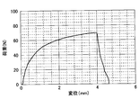
- No. 4 is a graph showing a relationship between displacement (mm) and load (N) in a bond strength evaluation test in test piece 4 for evaluation.
- FIG. 1 schematically shows an example of the structure of a vacuum double-layer glass according to the present invention.
- the vacuum double-glazed glass 100 includes a first glass substrate 110, a second glass substrate 120, a gap 130 formed between them, and a gap in a sealed state. And a sealing member 150 to be held on the surface.
- the first glass substrate 110 has a first surface 112 and a second surface 114.
- the first glass substrate 110 is disposed so that the first surface 112 side is the outside.
- the second glass substrate 120 has a first surface 122 and a second surface 124.
- the second glass substrate 120 is disposed such that the first surface 122 side is the outside. Accordingly, the gap 130 is formed between the second surface 114 of the first glass substrate 110 and the second surface 124 of the second glass substrate 120.
- the gap 130 is maintained in a vacuum state.
- the degree of vacuum of the gap 130 is not particularly limited, and may be any pressure lower than atmospheric pressure. In general, the pressure in the gap 130 is about 0.001 Pa to 0.2 Pa.
- the gap 130 may be filled with an inert gas such as argon at a pressure lower than atmospheric pressure. That is, in the present application, “vacuum multilayer glass” does not necessarily require that the pressure in the gap is in a vacuum state, and the term “vacuum multilayer glass” means that the pressure in the gap is less than atmospheric pressure. It shall mean all the laminated glass.
- an inert gas such as argon
- the vacuum multilayer glass 100 may have one or more spacers 190 in the gap 130.
- the spacer 190 has a role of holding the gap 130 in a desired shape.
- the gap 130 can be maintained in a desired shape without the spacer 190, for example, when the degree of vacuum of the gap 130 is low, or when an inert gas or the like is applied to the gap 130 at a certain pressure.
- the spacer 190 may be omitted.
- the seal member 150 is a member for holding the gap 130 in a sealed state.
- the seal member 150 is installed over the entire periphery of the gap 130.
- the seal member 150 is a so-called “hybrid seal member” including a metal member 155 and first and second vitrified layers 160 and 165.
- the glass solidified layers 160 and 165 are layers formed by heat-treating a paste containing glass frit or a glass bulk body (for example, glass fiber or glass ribbon), and contain a glass component.
- Patent Document 1 discloses a “hybrid seal member” in which a metal member and a low-melting-point ceramic frit are combined as a seal member for a vacuum double-layer glass.
- Patent Document 1 no consideration is given to the bonding force between the metal member and the low melting point ceramic frit.
- the bonding force between the metal member and the low melting point ceramic frit is an extremely important factor.
- the bonding force cannot be obtained between them, and the “hybrid seal member” may not be employed as a vacuum multilayer glass seal member. There is.
- Patent Document 1 exemplifies metal chromium and stainless steel as a metal for the “hybrid seal member”.
- metallic chromium is rarely applied as part of a structural member.
- the metal member and the low-melting-point ceramic frit are hardly bonded. Has been found.
- the bonding force between the metal member and the low melting point ceramic frit is extremely important.
- the metal member of the “hybrid seal member” has a tensile strength X (N / mm) in a room temperature tensile test (tensile speed: 1 mm / min) after being held at 490 ° C. in the atmosphere for 40 minutes. 2 ) and the elongation at break Y (%) are selected from materials satisfying Y ⁇ 0.10X.
- the above-mentioned heat treatment conditions for the metal member correspond to typical heat treatment conditions for forming the “hybrid seal member”, as will be described in detail later.
- FIG. 2 is a diagram schematically showing each step when a metal member and a glass solidified layer are bonded by heat treatment to form a hybrid seal member on a glass substrate.
- a metal member 210 and a glass substrate 250 are prepared. Further, the metal member 210 is disposed on the glass substrate 250 so as to overlap at least a part of the glass substrate 250. Thereby, the assembly 260 is configured.
- a glass solidified layer 270 is provided in advance on a part of the surface of the glass substrate 250.
- the glass solidified layer 270 is covered with a metal member 210 disposed on the glass substrate 250.
- the assembly 260 is kept at a high temperature for the heat treatment.
- the heat treatment is performed in order to bond the metal member 210 to the glass substrate 250 through the vitrified layer 270.
- the temperature of the heat treatment is in the range of 430 ° C. to 530 ° C. (eg, 490 ° C.).
- This heating causes the vitrified layer 270 to have fluidity.
- the metal member 210 is temporarily bonded to the glass substrate 250 through the fluidized glass solidified layer 270.
- the coefficient of thermal expansion differs greatly between metal and glass. Therefore, particularly when viewed in the Y direction in the figure, when the assembly 260 is heated, the metal member 210 stretches and exhibits a relatively large deformation, but the glass substrate 250 does not exhibit a significant stretch.
- the temperature of the assembly 260 starts to decrease from the heat treatment temperature.
- the fluidity of the vitrified layer 270 starts to decrease, and the vitrified layer 270 is cured.
- the metal member 210 is bonded to the glass substrate 250 through the glass solidified layer 270 to form a hybrid seal member.
- the temperature of the assembly 260 further decreases.
- the metal member 210 is already bonded to the vitrified layer 270, and therefore cannot be freely contracted in the Y direction even when the temperature is lowered. That is, the portion of the metal member 210 bonded to the vitrified layer 270 is constrained by the vitrified layer 270 and can only be deformed to the same extent as the shrinkage of the glass substrate 250 even if the temperature is lowered. .
- the metal member 210 has sufficient deformation tolerance, that is, when the metal member 210 has a relatively good elongation characteristic (elasticity), the metal member 210 is restrained by the vitrified layer 270. It is possible to follow the shrinkage behavior of the glass substrate 250 even if it is left. For this reason, when the assembly 260 is cooled to room temperature, a good bond is obtained between the metal member 210 and the vitrified layer 270 as shown in the upper diagram of FIG. As a result, a hybrid seal member with good sealing properties is formed.
- the metal member 210 does not have sufficient deformation tolerance, that is, when the metal member 210 does not have a very good elongation characteristic (elasticity), such a metal member 210 is particularly vitrified. It is not possible to follow the small shrinkage behavior of the glass substrate 250 at the location constrained by. For this reason, when the assembly 260 is cooled to room temperature, the metal member 210 is separated from the vitrified layer 270 as shown in the lower diagram of FIG. 2D, and the metal member 210 and the vitrified layer are separated. No bond can be obtained with 270. As a result, a hybrid seal member cannot be obtained.
- the elongation characteristics of the metal member 210 can be a significant factor that affects the bonding between the metal member 210 and the vitrified layer 270.
- condition A such a material selection condition is simply referred to as “condition A”.
- a material satisfying the above-mentioned condition A is selected as the metal member of the “hybrid seal member”, and thereby, good bondability can be obtained between the metal member and the vitrified layer. it can.
- the present invention even after the heat treatment is performed, it is possible to obtain a good bonding force between the metal member 155 and the glass solidified layer 250, and it is preferably applied to the vacuum double-layer glass.
- a “hybrid seal member” that can be obtained can be obtained.
- the seal member 150 includes a metal member 155 and first and second vitrified layers 160 and 165.
- the metal member 155 is selected from materials that satisfy the condition A in the room temperature tensile test after being held at 490 ° C. in the atmosphere for 40 minutes.
- the glass solidified layers 160 and 165 are formed by firing a paste containing glass frit or a glass bulk body (for example, glass fiber or glass ribbon).
- the vitrified layers 160 and 165 include a glass component, but may further include ceramic particles.
- first glass solidified layer 160 and the second glass solidified layer 165 may be the same or different.
- the thermal expansion coefficient of the glass solidified layers 160 and 165 at 50 ° C. to 250 ° C. may be, for example, in the range of 70 ⁇ 10 ⁇ 7 / K to 120 ⁇ 10 ⁇ 7 / K.
- the difference in the thermal expansion coefficient between the glass solidified layer and the glass substrate becomes small, and peeling at the interface between the glass solidified layer and the glass substrate hardly occurs.
- a sealing member having a strong bonding force between the glass solidified layer and the metal member can be provided. It is preferable to reduce the difference in thermal expansion coefficient.
- the composition of the glass component contained in the vitrified layers 160 and 165 is not particularly limited.
- the glass component contained in the vitrified layers 160 and 165 may be, for example, ZnO—Bi 2 O 3 —B 2 O 3 or ZnO—SnO—P 2 O 5 glass.
- Table 1 shows an example of the composition of a ZnO—Bi 2 O 3 —B 2 O 3 -based glass that can be used as a glass component included in the vitrified layers 160 and 165.
- Table 2 shows an example of the composition of ZnO—SnO—P 2 O 5 based glass that can be used for the glass components contained in the vitrified layers 160 and 165.
- the seal member 150 includes a metal member 155, a first glass solidified layer 160, and a second glass solidified layer 165.
- the metal member 155 has a substantially “Z” shape. That is, the metal member 155 is joined to the first vitrified layer 160 formed on the first glass substrate 110 at one end of the approximately “Z” shape, and the other end of the approximately “Z” shape is the second.
- the second glass solidified layer 165 formed on the glass substrate 120 is combined.
- the seal member 150 may have other configurations.
- the first glass solidified layer 160 is formed on the second surface 114 side of the first glass substrate 110 so as to face the second glass solidified layer 165, and the metal member has a cross-sectional shape of U. It has a letter shape and may be arranged between the two.
- the metal member may have a plate shape or a foil shape instead of a U-shaped cross section.
- the metal member may be formed by punching a metal plate into a frame shape along the periphery of the vacuum multilayer glass.
- the first glass solidified layer 160 is provided on the second surface 114 side of the first glass substrate 110, and the first glass solidified in plan view is provided on the second surface 124 side of the second glass substrate 120.
- a second vitrified layer 165 is provided at a position not overlapping with the layer 160.
- the metal member is disposed between the first and second glass solidified layers 160 and 165, and is heated together with the glass solidified layer to be bonded to the second surface 114 side of the first glass substrate 110, and Combined with the second surface 124 of the second glass substrate 120.
- the metal member is a foil or a plate and may have a thickness in the range of 0.03 mm to 0.5 mm.
- the thickness of the metal member is 0.03 mm or more, the possibility that the metal member is broken during production or a pinhole is generated is reduced.
- the thickness of the metal member is 0.5 mm or less, the metal member has sufficient tolerance for deformation, so that the metal member can follow the shrinkage behavior of the glass substrate and obtain a good bonding force with the glass solidified layer. It is done.
- the thickness of the metal member is more preferably 0.04 mm to 0.3 mm, and still more preferably 0.05 to 0.2 mm.
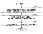
- FIG. 3 shows a flow chart of an example of a method for producing a vacuum double-glazed glass according to the present invention.
- the manufacturing method of the vacuum double-glazed glass according to the present invention includes: (A) forming a first glass solidified layer on the first glass substrate and forming a second glass solidified layer on the second glass substrate (step S110); (B) configuring an assembly in which the first and second glass substrates and the metal member are combined (step S120); (C) heating at least the first and second vitrified layers of the assembly to form a vacuum double-glazed glass (step S130);
- Step S110 First, the first and second glass substrates 110 and 120 are prepared.
- the first glass solidified layer 160 is formed on the first glass substrate 110, and the second glass solidified layer 165 is formed on the second glass substrate 120.
- the first glass solidified layer 160 is formed around the first surface 112 of the first glass substrate 110 will be described.
- a paste for the first vitrified layer 160 is prepared.
- the paste includes glass frit, ceramic particles, and a vehicle (organic binder and organic solvent).
- the ceramic particles may be omitted.
- the glass frit eventually becomes a glass component constituting the first vitrified layer 160.
- the prepared paste is applied around the first surface 112 of the first glass substrate 110.
- the first glass substrate 110 containing the paste is dried.
- the conditions for the drying treatment are not particularly limited as long as the organic solvent in the paste is removed.
- the drying process may be performed, for example, by holding the first glass substrate 110 at a temperature of 100 ° C. to 200 ° C. for about 1 minute to 1 hour.
- the first glass substrate 110 is heat-treated at a high temperature.
- the conditions for the heat treatment are not particularly limited as long as the organic binder contained in the paste is removed.
- the heat treatment may be performed, for example, by holding the first glass substrate 110 in a temperature range of 430 ° C. to 470 ° C. for about 1 minute to 1 hour. Thereby, the paste is temporarily fired, and the first vitrified layer 160 is formed.
- a second glass solidified layer 165 is formed around the second surface 124 of the second glass substrate 120.
- Step S120 Next, the first and second glass substrates 110 and 120 and the metal member 155 are combined to form an assembly. At this time, one or more spacers 190 may be disposed between the first glass substrate 110 and the second glass substrate 120 as necessary.
- the metal member 155 is formed in a plate shape or a foil shape, for example. Further, the metal member 155 may have a substantially “Z” shape. For example, the metal member 155 may have first and second ends, and both ends may be bent in directions opposite to each other. In that case, for example, the metal member 155 has a first end portion of the metal member 155 in contact with the first vitrified layer 160 and a second end portion in contact with the second vitrified layer 165.
- the first and second glass substrates 110 and 120 may be disposed.
- the metal member 155 has the tensile strength X (N / mm 2 ) in the “condition A”, that is, the room temperature tensile test (tensile speed: 1 mm / min) after being held in the atmosphere at 490 ° C. for 40 minutes. It should be noted that the relationship between the elongation at break Y (%) is selected from materials that satisfy Y ⁇ 0.10X.
- Examples of the metal material satisfying such “condition A” include pure aluminum, aluminum alloy, pure titanium, and titanium alloy.
- pure aluminum refers to aluminum having a purity of 99% or more, and aluminum having a purity of less than 99% is referred to as an aluminum alloy.
- those having a purity of 99% or more are defined as “pure”, and those having a purity of less than 99% are defined as “alloys”.
- the metal member 155 is preferably selected from materials that do not satisfy the “condition A” in this assembly stage (ie, the stage of step S120).
- the metal member 155 only needs to satisfy the condition A after the heat treatment (step S130) for forming a bond with the vitrified layer and functioning as a seal member.
- Such materials include pure aluminum and aluminum alloys. This is because pure aluminum and aluminum alloys include metal materials having an annealing temperature of about 490 ° C. Such a metal material can be used in a state of having a certain degree of rigidity (that is, not satisfying the condition A) in handling the assembly. After that, such a metal material is annealed in the middle of the heat treatment, satisfies the condition A in a state after the heat treatment, and exhibits good bonding with the vitrified layers 160 and 165.
- Step S130 Next, at least the vitrified layers 160, 165 of the assembly are heated.
- the heating conditions vary depending on the combination of the metal member 155 and the glass solidified layers 160, 165, etc., but for example, the assembly is brought to a temperature of about 470 ° C. to about 530 ° C. (eg, 490 ° C.) for 1 minute to 1 hour. After holding (for example, 40 minutes), cooling may be performed to room temperature.
- a more preferable temperature range is 470 ° C. to 520 ° C., more preferably 470 ° C. to 500 ° C., and a more preferable holding time is 1 minute to 45 minutes, and further preferably 1 minute to 30 minutes.
- the metal member 155 is selected from materials that satisfy the “condition A”. For this reason, during the heat treatment and cooling of the assembly, the metal member 155 cannot cope with the deformation behavior of the vitrified layers 160 and 165 and is significantly suppressed from separating from the vitrified layers 160 and 165. Is done. Therefore, a good bond is obtained between the metal member 155 and the vitrified layers 160 and 165 by the heat treatment of the assembly. After the heat treatment of the assembly, a gap 130 covered with the seal member 150 is formed between the first and second glass substrates 110 and 120.
- the inside of the gap portion 130 is decompressed using an opening provided in advance in the first and / or second glass substrate.
- the gas in the gap 130 is replaced with an inert gas, or the gap 130 is decompressed.
- the opening used for the decompression process is sealed. Thereby, the vacuum multilayer glass 100 is manufactured.
- heating the assembly When heating the assembly, it may be performed in a vacuum atmosphere. If heating is performed without providing an opening, the inside of the gap 130 is maintained in vacuum as it is, and the decompression process after heating can be omitted. Further, as a method for heating the assembly, a local heating method (infrared heating, electromagnetic induction heating, laser irradiation, etc.) for firing the vitrified layer may be used in addition to the method for heating the whole.
- a local heating method infrared heating, electromagnetic induction heating, laser irradiation, etc.
- Example 1 (Bindability evaluation test) About the combination of various metal members and a glass solidification layer, both bondability was evaluated with the following method.
- a glass substrate having a glass solidified layer was produced by the following method.
- a glass substrate (soda lime glass manufactured by Asahi Glass) having a length of 50 mm, a width of 230 mm, and a thickness of 2.8 mm was prepared.
- a glass solidified layer was formed on one end of the surface of the glass substrate by the following method.
- a paste containing glass frit, ceramic powder, and vehicle organic binder and organic solvent
- glass frit a ZnO—Bi 2 O 3 —B 2 O 3 composition shown in Table 4 was used.
- the thermal expansion coefficient of this glass frit is about 105 ⁇ 10 ⁇ 7 / K.
- cordierite was used as the ceramic powder, and a mixture of ethyl cellulose, propylene glycol diacetate (1,2-diacetoxypropane) and terpineol was used as the vehicle.
- this paste was applied to one end (about 230 mm ⁇ about 15 mm region) of one surface of the glass substrate.
- the glass substrate was heat-treated at 380 ° C. for 30 minutes, and the paste was temporarily fired. Thereby, the glass solidification layer was formed in the position which apply
- the metal plate of any of Samples 1 to 17 described above was placed on a glass substrate to obtain an assembly.
- the metal plate was placed on the glass substrate so that the vitrified layer portion was completely covered.
- the obtained assembly was held at 490 ° C. for 40 minutes, and then cooled to room temperature. Thereafter, it was evaluated whether or not the metal plate and the vitrified layer were bonded. The evaluation was performed based on whether the metal plate and the vitrified layer were in a bonded state or in a peeled state.
- the tensile test was performed by cutting each metal material plate into a rectangular shape (length 50 mm ⁇ width 10 mm) as a test piece, and fixing both ends in the longitudinal direction of the test piece to a tensile tester.
- the tensile strength and elongation at break of each metal material were measured at a distance between chucks of both ends of the test piece of 20 mm and a tensile speed of 1 mm / min.
- the thickness of each test piece was as shown in Table 3.
- the atmospheric temperature at the time of a test was normal temperature.
- each metal material of Samples 1 to 17 was heat-treated under the following conditions: after heating to 490 ° C. at a heating rate of 10 ° C./min, holding for 40 minutes, and then 10 ° C./min. At room temperature. This is to simulate the thermal history when the metal member is actually applied as part of the seal member.
- the values of the tensile strength and breaking elongation of each metal material of Samples 1 to 17 obtained by the tensile test are collectively shown in the column of “Tensile test results” in Table 3 above.
- the tensile strength was determined by dividing the load (N) when the test piece was broken by the cross-sectional area (mm 2 ) of the test piece.
- the elongation at break was defined as the elongation (%) before and after the tensile test at a distance between any two points of the test piece.
- the metal material bonded to the vitrified layer tends to have a relatively large elongation at break relative to the value of tensile strength, that is, a relatively ductile material. I found out.
- FIG. 4 is a graph plotting the relationship between tensile strength and elongation at break obtained in the tensile test of each metal material of Samples 1 to 17. Note that the plot symbol “ ⁇ ” indicates the value of the sample bonded to the vitrified layer in the above-described bondability evaluation test, and the plot symbol “x” indicates that in the bondability evaluation test. The value of the sample which did not couple
- certain types of pure aluminum and aluminum alloys have an annealing temperature in a temperature range of about 490 ° C.
- Such pure aluminum and aluminum alloy satisfy the above-mentioned “condition A” only by a heat treatment that is held at 490 ° C. in the atmosphere for 40 minutes. In other words, “condition A” is not satisfied until such heat treatment is performed.
- Such pure aluminum and aluminum alloy are particularly preferable as a metal member for a seal member.
- the metal member and the glass substrate are heated to manufacture the vacuum double-glazed glass having the “hybrid seal member”, that is, in the stage of assembling the assembly. This is because the handling property of is significantly improved.
- a material satisfying “Condition A” is characterized by being relatively soft.
- the handling property of the metal member is deteriorated.
- an aluminum alloy having an annealing temperature in a temperature range of about 490 ° C. it is used with a certain degree of rigidity when handling the assembly, and satisfies “condition A” after the heat treatment. Can be.
- Examples of pure aluminum and aluminum alloys that do not satisfy “Condition A” before the heat treatment but satisfy “Condition A” after the heat treatment include A3003-H18 of Sample 1 in Table 3, A1050-H24 of Sample 3, and Sample 6 and Sample 8 A1N30-H18.
- Table 5 summarizes the tensile test results of these pure aluminum and aluminum alloy before and after heat treatment. The conditions for the tensile test are the same as those described above.
- Example 2 Next, in the above-described bondability evaluation test, using the metal material sample with the result of “ ⁇ ”, that is, the metal material sample bonded to the vitrified layer, the following method is used to obtain the The binding force was evaluated quantitatively.
- test specimen for evaluation was produced by the following method.
- a glass substrate having a vitrified layer was produced by the same method as in Example 1 described above. However, the dimensions of the glass substrate were 9 mm long ⁇ 50 mm wide ⁇ 2.8 mm thick. The approximate size of the vitrified layer 520 was 5 mm long ⁇ 5 mm wide.
- the first metal member was pure aluminum A1050-H24, and the thickness was 0.2 mm.
- the second metal member was pure aluminum A1N30-H18, and the thickness was 0.1 mm.
- the third metal member was pure aluminum A1N30-H18, and the thickness was 0.15 mm.
- the dimension of the metal member was 50 mm long ⁇ 10 mm wide.
- the glass substrate and the metal member were heat-treated so as to overlap each other at the vitrified layer portion.
- the metal member was bonded to the glass substrate via the vitrified layer, and evaluation test pieces (No. 1 to No. 3) were produced.
- the heat treatment conditions were 40 minutes at 490 ° C. in the atmosphere.
- FIG. 5 shows a plan view of the obtained test specimen for evaluation.
- the test specimen 500 for evaluation has a glass substrate 510 and a metal member 530, and is arranged so that one end of the metal member 530 overlaps the glass solidified layer 520 formed on the glass substrate 510. It was made.
- the bonding strength evaluation test was conducted by pulling each test specimen for evaluation at room temperature until it was broken.
- Fig. 6 shows the outline of the test equipment.
- the test apparatus 600 includes a jig 610 for holding the evaluation test piece 500 and a holder 630 for pulling the evaluation test piece 500 upward.
- the glass substrate 510 side of the test piece 500 for evaluation was attached to the side surface 615 of the jig 610 using a double-sided adhesive tape. Further, the tip of the metal member 530 of the evaluation test piece 500 (the end on the side not bonded to the glass solidified layer 520) was attached to the holder 630. Further, a strain gauge (not shown) was attached to a predetermined position of the metal member 530 of the evaluation test piece 500.
- test piece 500 for evaluation was pulled in the direction of arrow F (upward) through the holder 630 while the jig 610 was fixed.
- the tensile speed was 1 mm / min. The test was continued until the test specimen 500 for evaluation broke, and the load (N) and displacement (mm) when the test specimen 500 for evaluation broke were measured.
- FIG. 1 shows the relationship between the displacement (mm) and the load (N) at the time of measurement in the test piece for evaluation 1.
- Example 3 an evaluation test piece was prepared in the same manner as in Example 2 except that pure titanium (TR270C-O) having a thickness of 0.1 mm was used as the metal member of the evaluation test piece. A bond strength evaluation test was performed using the test specimen for evaluation.
- test piece for evaluation (No. 4) is shown in Table 7 below.
- FIG. 8 shows the result of the bond strength evaluation test on the test piece 4 for evaluation.
- rupture of the test piece for evaluation of 4 was peeling of the interface of a metal member and a glass solidification layer.
- FIG. 4 shows the relationship between the displacement (mm) and the load (N) until the interface between the metal member of the evaluation test piece 4 and the vitrified layer is peeled off.
- FIG. 1-No The relationship between the displacement (mm) and the load (N) until the interface between the metal member and the vitrified layer in the test piece for evaluation of No. 4 is peeled off is shown in FIG. 1-No. It can be seen that the relationship between the displacement (mm) and the load (N) as a result of the fracture of the metal member in the evaluation test piece 3 is greatly different.
- No. No. 4 test piece is No. 4.
- 1-No. 3 shows a rupture mode in which the interface between the metal member and the vitrified layer is peeled, unlike the rupture mode of the test piece for evaluation 3 (rupture of the metal member). Also in the test piece for evaluation of No. 4, it was confirmed that a good bond was obtained between the metal member and the vitrified layer.
- condition A As described above, whether or not the metal material held in the atmosphere at 490 ° C. for 40 minutes satisfies the “condition A” as a criterion for the determination as to whether or not the metal material tends to bond with the vitrified layer. It was confirmed that it could be judged.
- Example 4 A glass ribbon having a composition of ZnO—SnO—P 2 O 5 series of 5 mm length ⁇ 15 mm width ⁇ 0.1 mm thickness on a glass substrate (Asahi Glass soda lime glass) of 10 mm long ⁇ 20 mm wide ⁇ 2.8 mm thick. Then, a test piece in which a metal plate made of pure aluminum (A1N30-H18) having a length of 10 mm, a width of 20 mm, and a thickness of 0.1 mm was prepared and heat-treated. The heat treatment was performed at 450 ° C. for 10 minutes.
- composition of the ZnO—SnO—P 2 O 5 glass ribbon is as follows: P 2 O 5 is 30%, SnO is 32%, ZnO is 36%, B 2 O 3 is 1%, and CaO is 0.5%. Al 2 O 3 was 0.5%.
- the glass ribbon was softened by the heat treatment, and the glass substrate and the metal plate were joined.
- the result of the connectivity evaluation test similar to that in Example 1 was “ ⁇ ”.
- the present invention can be used for vacuum double glazing and the like used for window glass of buildings.
Landscapes
- Chemical & Material Sciences (AREA)
- Engineering & Computer Science (AREA)
- Geochemistry & Mineralogy (AREA)
- Life Sciences & Earth Sciences (AREA)
- Chemical Kinetics & Catalysis (AREA)
- General Chemical & Material Sciences (AREA)
- Materials Engineering (AREA)
- Organic Chemistry (AREA)
- Civil Engineering (AREA)
- Structural Engineering (AREA)
- Ceramic Engineering (AREA)
- Joining Of Glass To Other Materials (AREA)
- Glass Compositions (AREA)
- Securing Of Glass Panes Or The Like (AREA)
Abstract
Priority Applications (6)
| Application Number | Priority Date | Filing Date | Title |
|---|---|---|---|
| JP2014510218A JP6052286B2 (ja) | 2012-04-13 | 2013-04-12 | 真空複層ガラスおよびシール部材並びに真空複層ガラスの製造方法 |
| CA2869996A CA2869996A1 (fr) | 2012-04-13 | 2013-04-12 | Verre multicouches a vide d'air, element d'etancheite et procede de fabrication d'un verre multicouches a vide d'air |
| RU2014145553A RU2014145553A (ru) | 2012-04-13 | 2013-04-12 | Вакуумный изолирующий стеклопакет, уплотнение и способ изготовления вакуумного изолирующего стеклопакета |
| CN201380019284.2A CN104220394A (zh) | 2012-04-13 | 2013-04-12 | 真空复层玻璃和密封构件以及真空复层玻璃的制造方法 |
| EP13775947.8A EP2837607A4 (fr) | 2012-04-13 | 2013-04-12 | Verre multicouches à vide d'air, élément d'étanchéité et procédé de fabrication d'un verre multicouches à vide d'air |
| US14/512,695 US20150030789A1 (en) | 2012-04-13 | 2014-10-13 | Vacuum insulating glazing, a sealing, and a method of producing vacuum insulating glazing |
Applications Claiming Priority (2)
| Application Number | Priority Date | Filing Date | Title |
|---|---|---|---|
| JP2012-092368 | 2012-04-13 | ||
| JP2012092368 | 2012-04-13 |
Related Child Applications (1)
| Application Number | Title | Priority Date | Filing Date |
|---|---|---|---|
| US14/512,695 Continuation US20150030789A1 (en) | 2012-04-13 | 2014-10-13 | Vacuum insulating glazing, a sealing, and a method of producing vacuum insulating glazing |
Publications (1)
| Publication Number | Publication Date |
|---|---|
| WO2013154193A1 true WO2013154193A1 (fr) | 2013-10-17 |
Family
ID=49327751
Family Applications (1)
| Application Number | Title | Priority Date | Filing Date |
|---|---|---|---|
| PCT/JP2013/061128 Ceased WO2013154193A1 (fr) | 2012-04-13 | 2013-04-12 | Verre multicouches à vide d'air, élément d'étanchéité et procédé de fabrication d'un verre multicouches à vide d'air |
Country Status (7)
| Country | Link |
|---|---|
| US (1) | US20150030789A1 (fr) |
| EP (1) | EP2837607A4 (fr) |
| JP (1) | JP6052286B2 (fr) |
| CN (1) | CN104220394A (fr) |
| CA (1) | CA2869996A1 (fr) |
| RU (1) | RU2014145553A (fr) |
| WO (1) | WO2013154193A1 (fr) |
Cited By (3)
| Publication number | Priority date | Publication date | Assignee | Title |
|---|---|---|---|---|
| WO2015056599A1 (fr) * | 2013-10-18 | 2015-04-23 | 旭硝子株式会社 | Procédé de production de verre multicouche sous vide |
| WO2015056606A1 (fr) * | 2013-10-18 | 2015-04-23 | 旭硝子株式会社 | Procédé de fabrication de verre feuilleté sous vide |
| WO2016088781A1 (fr) * | 2014-12-02 | 2016-06-09 | 株式会社Neomaxマテリアル | Matériau de liaison de verre et verre multicouche |
Families Citing this family (7)
| Publication number | Priority date | Publication date | Assignee | Title |
|---|---|---|---|---|
| CN106285336A (zh) * | 2015-05-18 | 2017-01-04 | 深圳市雅丹幕墙工程有限公司 | 建筑玻璃的再利用结构 |
| CN104961357B (zh) * | 2015-07-07 | 2017-06-27 | 哈尔滨工业大学(威海) | 一种k9玻璃与钛金属低温连接方法 |
| EP3583080B1 (fr) * | 2017-02-17 | 2024-01-03 | VKR Holding A/S | Traitement thermique de fritte supérieure |
| US12091907B2 (en) | 2018-12-21 | 2024-09-17 | Vkr Holding A/S | Vacuum insulated glazing unit with dense side seal material |
| US11732526B2 (en) * | 2019-03-27 | 2023-08-22 | Halio, Inc. | Shear stress reduction in electrochromic device assemblies |
| EP4164995A4 (fr) * | 2020-06-11 | 2024-06-26 | V-Glass, Inc. | Joint d'étanchéité hermétique à deux étages et procédé de fabrication de celui-ci |
| CN115259696B (zh) * | 2022-08-16 | 2025-04-11 | 昆山浦元真空技术工程有限公司 | 真空玻璃的真空密封工艺及其所用的真空密封设备 |
Citations (3)
| Publication number | Priority date | Publication date | Assignee | Title |
|---|---|---|---|---|
| WO2008085325A2 (fr) * | 2007-01-10 | 2008-07-17 | Guardian Industries Corp. | Unité de vitrage à isolation sous vide (ig) comprenant un joint de bord étanche à élément métallique |
| JP2010530838A (ja) * | 2007-06-23 | 2010-09-16 | フラウンホファー ゲセルシャフト ツール フェールデルンク ダー アンゲヴァンテン フォルシュンク エー.ファオ. | ガラスろう又は金属ろうでろう付けすることにより2つの部材を恒久的に結合する方法 |
| WO2011072646A2 (fr) * | 2009-12-18 | 2011-06-23 | Futech Gmbh | Élément de vitrage thermo-isolant et son procédé de production |
Family Cites Families (11)
| Publication number | Priority date | Publication date | Assignee | Title |
|---|---|---|---|---|
| US2094287A (en) * | 1935-05-13 | 1937-09-28 | Owens Illinois Glass Co | Method of manufacturing multipart glass articles |
| US2708774A (en) * | 1949-11-29 | 1955-05-24 | Rca Corp | Multiple glazed unit |
| US3887883A (en) * | 1973-10-29 | 1975-06-03 | Lewayne E Garman | Gas laser tube and method of fabricating same |
| US4393105A (en) * | 1981-04-20 | 1983-07-12 | Spire Corporation | Method of fabricating a thermal pane window and product |
| DE19906521C2 (de) * | 1999-02-17 | 2003-03-27 | Schott Glas | Sprödbrüchiger Formkörper, zusammengefügt aus Glasteilen aus Hartglas und/oder Glaskeramik-Teilen und Verfahren zu seiner Herstellung |
| US6399169B1 (en) * | 1999-07-07 | 2002-06-04 | Guardian Industries Corp. | Vacuum IG window unit with dual peripheral seal |
| JP2005320229A (ja) * | 2004-04-08 | 2005-11-17 | Nippon Sheet Glass Co Ltd | 減圧ガラスパネル及びその製造方法 |
| JP4774721B2 (ja) * | 2004-11-12 | 2011-09-14 | 旭硝子株式会社 | 低融点ガラスおよび封着用組成物ならびに封着用ペースト |
| TW200624402A (en) * | 2004-11-12 | 2006-07-16 | Asahi Techno Glass Corp | Low melting glass, sealing composition and sealing paste |
| CN101681965A (zh) * | 2007-05-30 | 2010-03-24 | 旭硝子株式会社 | 光学元件覆盖用玻璃、覆盖有玻璃的发光元件及覆盖有玻璃的发光装置 |
| US8648010B2 (en) * | 2009-12-25 | 2014-02-11 | Kao Corporation | Thermal transfer image-receiving sheets |
-
2013
- 2013-04-12 WO PCT/JP2013/061128 patent/WO2013154193A1/fr not_active Ceased
- 2013-04-12 JP JP2014510218A patent/JP6052286B2/ja not_active Expired - Fee Related
- 2013-04-12 CA CA2869996A patent/CA2869996A1/fr not_active Abandoned
- 2013-04-12 CN CN201380019284.2A patent/CN104220394A/zh active Pending
- 2013-04-12 RU RU2014145553A patent/RU2014145553A/ru not_active Application Discontinuation
- 2013-04-12 EP EP13775947.8A patent/EP2837607A4/fr not_active Withdrawn
-
2014
- 2014-10-13 US US14/512,695 patent/US20150030789A1/en not_active Abandoned
Patent Citations (4)
| Publication number | Priority date | Publication date | Assignee | Title |
|---|---|---|---|---|
| WO2008085325A2 (fr) * | 2007-01-10 | 2008-07-17 | Guardian Industries Corp. | Unité de vitrage à isolation sous vide (ig) comprenant un joint de bord étanche à élément métallique |
| EP2099997A2 (fr) | 2007-01-10 | 2009-09-16 | Guardian Industries Corp. | Unité de vitrage à isolation sous vide (ig) comprenant un joint de bord étanche à élément métallique |
| JP2010530838A (ja) * | 2007-06-23 | 2010-09-16 | フラウンホファー ゲセルシャフト ツール フェールデルンク ダー アンゲヴァンテン フォルシュンク エー.ファオ. | ガラスろう又は金属ろうでろう付けすることにより2つの部材を恒久的に結合する方法 |
| WO2011072646A2 (fr) * | 2009-12-18 | 2011-06-23 | Futech Gmbh | Élément de vitrage thermo-isolant et son procédé de production |
Non-Patent Citations (1)
| Title |
|---|
| See also references of EP2837607A4 |
Cited By (5)
| Publication number | Priority date | Publication date | Assignee | Title |
|---|---|---|---|---|
| WO2015056599A1 (fr) * | 2013-10-18 | 2015-04-23 | 旭硝子株式会社 | Procédé de production de verre multicouche sous vide |
| WO2015056606A1 (fr) * | 2013-10-18 | 2015-04-23 | 旭硝子株式会社 | Procédé de fabrication de verre feuilleté sous vide |
| WO2016088781A1 (fr) * | 2014-12-02 | 2016-06-09 | 株式会社Neomaxマテリアル | Matériau de liaison de verre et verre multicouche |
| JP2016108163A (ja) * | 2014-12-02 | 2016-06-20 | 株式会社Neomaxマテリアル | ガラス接合用材および複層ガラス |
| US10696589B2 (en) | 2014-12-02 | 2020-06-30 | Hitachi Metals, Ltd. | Glass bonding material and multilayer glass |
Also Published As
| Publication number | Publication date |
|---|---|
| US20150030789A1 (en) | 2015-01-29 |
| CN104220394A (zh) | 2014-12-17 |
| RU2014145553A (ru) | 2016-06-10 |
| CA2869996A1 (fr) | 2013-10-17 |
| JPWO2013154193A1 (ja) | 2015-12-21 |
| EP2837607A4 (fr) | 2016-04-27 |
| JP6052286B2 (ja) | 2016-12-27 |
| EP2837607A1 (fr) | 2015-02-18 |
Similar Documents
| Publication | Publication Date | Title |
|---|---|---|
| JP6052286B2 (ja) | 真空複層ガラスおよびシール部材並びに真空複層ガラスの製造方法 | |
| JP6495928B2 (ja) | 真空断熱ガラス(vig)ユニットに使用されるフリット、及び/又は関連方法 | |
| JP4251609B2 (ja) | ガラスパネル | |
| CN1277778C (zh) | 玻璃面板的制造方法和以该方法制造的玻璃面板 | |
| JP6500902B2 (ja) | 真空複層ガラスの製造方法、および真空複層ガラス | |
| US7244480B2 (en) | Glass panel | |
| JP5644129B2 (ja) | 強化板ガラス及びその製造方法 | |
| CN102471151B (zh) | 带密封材料层的玻璃构件以及使用该构件的电子器件及其制造方法 | |
| JP2017509573A (ja) | 無鉛二重フリット端部シールを有する真空断熱ガラス(vig)ユニット及び/又はその製造方法 | |
| EP2907795A1 (fr) | Double vitrage, et procédé de fabrication de double vitrage | |
| JP2018058709A (ja) | 真空断熱部材、それに用いる封止材料、及び真空断熱部材の製造方法 | |
| JP2014521586A (ja) | 倍強度真空ガラス | |
| CN111556856B (zh) | 密封材料和使用其的多层玻璃面板 | |
| WO2018207435A1 (fr) | Double vitrage et son procédé de fabrication | |
| JP2008201662A (ja) | 排気複層ガラスの製造方法 | |
| JP2017019697A (ja) | 真空気密体の製造方法 | |
| CN105873875A (zh) | 玻璃板用间隔保持部件及其制造方法 | |
| WO2001028952A1 (fr) | Panneau de verre et son procede de production | |
| EP3228606B1 (fr) | Matériau de liaison de verre et verre multicouche | |
| WO2003035567A1 (fr) | Double vitrage a vide | |
| WO2020050302A1 (fr) | Verre sous vide et procédé pour sa fabrication | |
| CN114541933A (zh) | 一种真空玻璃的封边结构及其封边方法 | |
| JP2014080313A (ja) | 複層ガラスおよび複層ガラスの製造方法 | |
| JP2016040212A (ja) | 真空複層ガラスの製造方法 | |
| WO2015056599A1 (fr) | Procédé de production de verre multicouche sous vide |
Legal Events
| Date | Code | Title | Description |
|---|---|---|---|
| 121 | Ep: the epo has been informed by wipo that ep was designated in this application |
Ref document number: 13775947 Country of ref document: EP Kind code of ref document: A1 |
|
| ENP | Entry into the national phase |
Ref document number: 2014510218 Country of ref document: JP Kind code of ref document: A |
|
| ENP | Entry into the national phase |
Ref document number: 2869996 Country of ref document: CA |
|
| NENP | Non-entry into the national phase |
Ref country code: DE |
|
| REEP | Request for entry into the european phase |
Ref document number: 2013775947 Country of ref document: EP |
|
| WWE | Wipo information: entry into national phase |
Ref document number: 2013775947 Country of ref document: EP |
|
| ENP | Entry into the national phase |
Ref document number: 2014145553 Country of ref document: RU Kind code of ref document: A |