WO2013157125A1 - Soupape de commande hydraulique et dispositif de commande hydraulique - Google Patents
Soupape de commande hydraulique et dispositif de commande hydraulique Download PDFInfo
- Publication number
- WO2013157125A1 WO2013157125A1 PCT/JP2012/060606 JP2012060606W WO2013157125A1 WO 2013157125 A1 WO2013157125 A1 WO 2013157125A1 JP 2012060606 W JP2012060606 W JP 2012060606W WO 2013157125 A1 WO2013157125 A1 WO 2013157125A1
- Authority
- WO
- WIPO (PCT)
- Prior art keywords
- piston
- pressure chamber
- valve
- pressure
- hydraulic control
- Prior art date
- Legal status (The legal status is an assumption and is not a legal conclusion. Google has not performed a legal analysis and makes no representation as to the accuracy of the status listed.)
- Ceased
Links
Images









Classifications
-
- F—MECHANICAL ENGINEERING; LIGHTING; HEATING; WEAPONS; BLASTING
- F15—FLUID-PRESSURE ACTUATORS; HYDRAULICS OR PNEUMATICS IN GENERAL
- F15B—SYSTEMS ACTING BY MEANS OF FLUIDS IN GENERAL; FLUID-PRESSURE ACTUATORS, e.g. SERVOMOTORS; DETAILS OF FLUID-PRESSURE SYSTEMS, NOT OTHERWISE PROVIDED FOR
- F15B11/00—Servomotor systems without provision for follow-up action; Circuits therefor
- F15B11/08—Servomotor systems without provision for follow-up action; Circuits therefor with only one servomotor
- F15B11/10—Servomotor systems without provision for follow-up action; Circuits therefor with only one servomotor in which the servomotor position is a function of the pressure also pressure regulators as operating means for such systems, the device itself may be a position indicating system
-
- F—MECHANICAL ENGINEERING; LIGHTING; HEATING; WEAPONS; BLASTING
- F15—FLUID-PRESSURE ACTUATORS; HYDRAULICS OR PNEUMATICS IN GENERAL
- F15B—SYSTEMS ACTING BY MEANS OF FLUIDS IN GENERAL; FLUID-PRESSURE ACTUATORS, e.g. SERVOMOTORS; DETAILS OF FLUID-PRESSURE SYSTEMS, NOT OTHERWISE PROVIDED FOR
- F15B13/00—Details of servomotor systems ; Valves for servomotor systems
- F15B13/02—Fluid distribution or supply devices characterised by their adaptation to the control of servomotors
- F15B13/04—Fluid distribution or supply devices characterised by their adaptation to the control of servomotors for use with a single servomotor
- F15B13/042—Fluid distribution or supply devices characterised by their adaptation to the control of servomotors for use with a single servomotor operated by fluid pressure
- F15B13/043—Fluid distribution or supply devices characterised by their adaptation to the control of servomotors for use with a single servomotor operated by fluid pressure with electrically-controlled pilot valves
- F15B13/0433—Fluid distribution or supply devices characterised by their adaptation to the control of servomotors for use with a single servomotor operated by fluid pressure with electrically-controlled pilot valves the pilot valves being pressure control valves
-
- F—MECHANICAL ENGINEERING; LIGHTING; HEATING; WEAPONS; BLASTING
- F15—FLUID-PRESSURE ACTUATORS; HYDRAULICS OR PNEUMATICS IN GENERAL
- F15B—SYSTEMS ACTING BY MEANS OF FLUIDS IN GENERAL; FLUID-PRESSURE ACTUATORS, e.g. SERVOMOTORS; DETAILS OF FLUID-PRESSURE SYSTEMS, NOT OTHERWISE PROVIDED FOR
- F15B13/00—Details of servomotor systems ; Valves for servomotor systems
- F15B13/02—Fluid distribution or supply devices characterised by their adaptation to the control of servomotors
- F15B13/04—Fluid distribution or supply devices characterised by their adaptation to the control of servomotors for use with a single servomotor
- F15B13/0401—Valve members; Fluid interconnections therefor
- F15B13/0405—Valve members; Fluid interconnections therefor for seat valves, i.e. poppet valves
-
- F—MECHANICAL ENGINEERING; LIGHTING; HEATING; WEAPONS; BLASTING
- F15—FLUID-PRESSURE ACTUATORS; HYDRAULICS OR PNEUMATICS IN GENERAL
- F15B—SYSTEMS ACTING BY MEANS OF FLUIDS IN GENERAL; FLUID-PRESSURE ACTUATORS, e.g. SERVOMOTORS; DETAILS OF FLUID-PRESSURE SYSTEMS, NOT OTHERWISE PROVIDED FOR
- F15B2211/00—Circuits for servomotor systems
- F15B2211/20—Fluid pressure source, e.g. accumulator or variable axial piston pump
- F15B2211/205—Systems with pumps
- F15B2211/2053—Type of pump
- F15B2211/20538—Type of pump constant capacity
-
- F—MECHANICAL ENGINEERING; LIGHTING; HEATING; WEAPONS; BLASTING
- F15—FLUID-PRESSURE ACTUATORS; HYDRAULICS OR PNEUMATICS IN GENERAL
- F15B—SYSTEMS ACTING BY MEANS OF FLUIDS IN GENERAL; FLUID-PRESSURE ACTUATORS, e.g. SERVOMOTORS; DETAILS OF FLUID-PRESSURE SYSTEMS, NOT OTHERWISE PROVIDED FOR
- F15B2211/00—Circuits for servomotor systems
- F15B2211/40—Flow control
- F15B2211/405—Flow control characterised by the type of flow control means or valve
- F15B2211/40507—Flow control characterised by the type of flow control means or valve with constant throttles or orifices
-
- F—MECHANICAL ENGINEERING; LIGHTING; HEATING; WEAPONS; BLASTING
- F15—FLUID-PRESSURE ACTUATORS; HYDRAULICS OR PNEUMATICS IN GENERAL
- F15B—SYSTEMS ACTING BY MEANS OF FLUIDS IN GENERAL; FLUID-PRESSURE ACTUATORS, e.g. SERVOMOTORS; DETAILS OF FLUID-PRESSURE SYSTEMS, NOT OTHERWISE PROVIDED FOR
- F15B2211/00—Circuits for servomotor systems
- F15B2211/40—Flow control
- F15B2211/405—Flow control characterised by the type of flow control means or valve
- F15B2211/40515—Flow control characterised by the type of flow control means or valve with variable throttles or orifices
-
- F—MECHANICAL ENGINEERING; LIGHTING; HEATING; WEAPONS; BLASTING
- F15—FLUID-PRESSURE ACTUATORS; HYDRAULICS OR PNEUMATICS IN GENERAL
- F15B—SYSTEMS ACTING BY MEANS OF FLUIDS IN GENERAL; FLUID-PRESSURE ACTUATORS, e.g. SERVOMOTORS; DETAILS OF FLUID-PRESSURE SYSTEMS, NOT OTHERWISE PROVIDED FOR
- F15B2211/00—Circuits for servomotor systems
- F15B2211/40—Flow control
- F15B2211/41—Flow control characterised by the positions of the valve element
- F15B2211/413—Flow control characterised by the positions of the valve element the positions being continuously variable, e.g. as realised by proportional valves
-
- F—MECHANICAL ENGINEERING; LIGHTING; HEATING; WEAPONS; BLASTING
- F15—FLUID-PRESSURE ACTUATORS; HYDRAULICS OR PNEUMATICS IN GENERAL
- F15B—SYSTEMS ACTING BY MEANS OF FLUIDS IN GENERAL; FLUID-PRESSURE ACTUATORS, e.g. SERVOMOTORS; DETAILS OF FLUID-PRESSURE SYSTEMS, NOT OTHERWISE PROVIDED FOR
- F15B2211/00—Circuits for servomotor systems
- F15B2211/40—Flow control
- F15B2211/415—Flow control characterised by the connections of the flow control means in the circuit
- F15B2211/41572—Flow control characterised by the connections of the flow control means in the circuit being connected to a pressure source and an output member
-
- F—MECHANICAL ENGINEERING; LIGHTING; HEATING; WEAPONS; BLASTING
- F15—FLUID-PRESSURE ACTUATORS; HYDRAULICS OR PNEUMATICS IN GENERAL
- F15B—SYSTEMS ACTING BY MEANS OF FLUIDS IN GENERAL; FLUID-PRESSURE ACTUATORS, e.g. SERVOMOTORS; DETAILS OF FLUID-PRESSURE SYSTEMS, NOT OTHERWISE PROVIDED FOR
- F15B2211/00—Circuits for servomotor systems
- F15B2211/40—Flow control
- F15B2211/415—Flow control characterised by the connections of the flow control means in the circuit
- F15B2211/41581—Flow control characterised by the connections of the flow control means in the circuit being connected to an output member and a return line
-
- F—MECHANICAL ENGINEERING; LIGHTING; HEATING; WEAPONS; BLASTING
- F15—FLUID-PRESSURE ACTUATORS; HYDRAULICS OR PNEUMATICS IN GENERAL
- F15B—SYSTEMS ACTING BY MEANS OF FLUIDS IN GENERAL; FLUID-PRESSURE ACTUATORS, e.g. SERVOMOTORS; DETAILS OF FLUID-PRESSURE SYSTEMS, NOT OTHERWISE PROVIDED FOR
- F15B2211/00—Circuits for servomotor systems
- F15B2211/40—Flow control
- F15B2211/42—Flow control characterised by the type of actuation
- F15B2211/426—Flow control characterised by the type of actuation electrically or electronically
-
- F—MECHANICAL ENGINEERING; LIGHTING; HEATING; WEAPONS; BLASTING
- F15—FLUID-PRESSURE ACTUATORS; HYDRAULICS OR PNEUMATICS IN GENERAL
- F15B—SYSTEMS ACTING BY MEANS OF FLUIDS IN GENERAL; FLUID-PRESSURE ACTUATORS, e.g. SERVOMOTORS; DETAILS OF FLUID-PRESSURE SYSTEMS, NOT OTHERWISE PROVIDED FOR
- F15B2211/00—Circuits for servomotor systems
- F15B2211/40—Flow control
- F15B2211/455—Control of flow in the feed line, i.e. meter-in control
-
- F—MECHANICAL ENGINEERING; LIGHTING; HEATING; WEAPONS; BLASTING
- F15—FLUID-PRESSURE ACTUATORS; HYDRAULICS OR PNEUMATICS IN GENERAL
- F15B—SYSTEMS ACTING BY MEANS OF FLUIDS IN GENERAL; FLUID-PRESSURE ACTUATORS, e.g. SERVOMOTORS; DETAILS OF FLUID-PRESSURE SYSTEMS, NOT OTHERWISE PROVIDED FOR
- F15B2211/00—Circuits for servomotor systems
- F15B2211/40—Flow control
- F15B2211/46—Control of flow in the return line, i.e. meter-out control
-
- F—MECHANICAL ENGINEERING; LIGHTING; HEATING; WEAPONS; BLASTING
- F15—FLUID-PRESSURE ACTUATORS; HYDRAULICS OR PNEUMATICS IN GENERAL
- F15B—SYSTEMS ACTING BY MEANS OF FLUIDS IN GENERAL; FLUID-PRESSURE ACTUATORS, e.g. SERVOMOTORS; DETAILS OF FLUID-PRESSURE SYSTEMS, NOT OTHERWISE PROVIDED FOR
- F15B2211/00—Circuits for servomotor systems
- F15B2211/50—Pressure control
- F15B2211/515—Pressure control characterised by the connections of the pressure control means in the circuit
- F15B2211/5158—Pressure control characterised by the connections of the pressure control means in the circuit being connected to a pressure source and an output member
-
- F—MECHANICAL ENGINEERING; LIGHTING; HEATING; WEAPONS; BLASTING
- F15—FLUID-PRESSURE ACTUATORS; HYDRAULICS OR PNEUMATICS IN GENERAL
- F15B—SYSTEMS ACTING BY MEANS OF FLUIDS IN GENERAL; FLUID-PRESSURE ACTUATORS, e.g. SERVOMOTORS; DETAILS OF FLUID-PRESSURE SYSTEMS, NOT OTHERWISE PROVIDED FOR
- F15B2211/00—Circuits for servomotor systems
- F15B2211/50—Pressure control
- F15B2211/515—Pressure control characterised by the connections of the pressure control means in the circuit
- F15B2211/5159—Pressure control characterised by the connections of the pressure control means in the circuit being connected to an output member and a return line
-
- F—MECHANICAL ENGINEERING; LIGHTING; HEATING; WEAPONS; BLASTING
- F15—FLUID-PRESSURE ACTUATORS; HYDRAULICS OR PNEUMATICS IN GENERAL
- F15B—SYSTEMS ACTING BY MEANS OF FLUIDS IN GENERAL; FLUID-PRESSURE ACTUATORS, e.g. SERVOMOTORS; DETAILS OF FLUID-PRESSURE SYSTEMS, NOT OTHERWISE PROVIDED FOR
- F15B2211/00—Circuits for servomotor systems
- F15B2211/50—Pressure control
- F15B2211/52—Pressure control characterised by the type of actuation
- F15B2211/528—Pressure control characterised by the type of actuation actuated by fluid pressure
-
- F—MECHANICAL ENGINEERING; LIGHTING; HEATING; WEAPONS; BLASTING
- F15—FLUID-PRESSURE ACTUATORS; HYDRAULICS OR PNEUMATICS IN GENERAL
- F15B—SYSTEMS ACTING BY MEANS OF FLUIDS IN GENERAL; FLUID-PRESSURE ACTUATORS, e.g. SERVOMOTORS; DETAILS OF FLUID-PRESSURE SYSTEMS, NOT OTHERWISE PROVIDED FOR
- F15B2211/00—Circuits for servomotor systems
- F15B2211/50—Pressure control
- F15B2211/575—Pilot pressure control
-
- F—MECHANICAL ENGINEERING; LIGHTING; HEATING; WEAPONS; BLASTING
- F15—FLUID-PRESSURE ACTUATORS; HYDRAULICS OR PNEUMATICS IN GENERAL
- F15B—SYSTEMS ACTING BY MEANS OF FLUIDS IN GENERAL; FLUID-PRESSURE ACTUATORS, e.g. SERVOMOTORS; DETAILS OF FLUID-PRESSURE SYSTEMS, NOT OTHERWISE PROVIDED FOR
- F15B2211/00—Circuits for servomotor systems
- F15B2211/60—Circuit components or control therefor
- F15B2211/665—Methods of control using electronic components
- F15B2211/6653—Pressure control
Definitions
- the present invention relates to a valve for controlling oil pressure by opening and closing an oil passage and a device including the valve, and more particularly to a balance piston valve and a hydraulic control device including the balance piston valve.
- the hydraulic control is generally performed by supplying pressure oil to the controlled object or by discharging the pressure oil from the controlled object, and is further supplied to the controlled object, or Adjusting the pressure of the pressure oil discharged from the controlled object is also included in the hydraulic control. If hydraulic pressure is used, power can be transmitted to remote locations, and hydraulic pressure also has a function to transmit signals. Therefore, hydraulic or hydraulic control devices are frequently used in various moving bodies and industrial equipment including vehicles. Has been. An example of a hydraulic control device for a vehicle is described in Japanese Patent Application Laid-Open No. 2011-163393.
- the hydraulic control device described in this publication is a hydraulic control device in a belt type continuously variable transmission for a vehicle, and a pressure increasing on / off valve for controlling the hydraulic pressure supplied to the hydraulic chamber in the primary pulley and the hydraulic chamber thereof And a pressure reducing on / off valve for controlling the hydraulic pressure discharged from the exhaust gas.
- a pressure increasing on / off valve for controlling the hydraulic pressure supplied to the hydraulic chamber in the secondary pulley and a pressure reducing on / off valve for controlling the hydraulic pressure discharged from the hydraulic chamber are provided.
- Each of these on-off valves includes an input port to which high hydraulic pressure is applied, an output port for discharging pressure oil flowing from the input port, and a solenoid for opening and closing the input port.
- the valve body that closes the input port is integrated with a plunger that is moved in the axial direction by the electromagnetic force of the solenoid.
- the plunger and the valve body are pressed toward the input port by a spring and resists the elastic force of the spring.
- An electromagnetic force is generated by a solenoid. Accordingly, since the valve having such a configuration is configured to close the input port by the elastic force of the spring, when the hydraulic pressure acting on the input port is high, the spring having a large elastic force, that is, a large spring coefficient.
- a spring will be used, and a large solenoid capable of generating a large electromagnetic force will be used.
- JP-A-11-101360 discloses a balanced solenoid valve.
- This solenoid valve has a communication passage that connects a positive pressure chamber on the front side of a piston integrated with a valve body and a back pressure chamber on the opposite side thereof, and the piston is provided, for example, in the back pressure chamber.
- the spring is pressed toward the positive pressure chamber side, and the valve body integrated with the piston is pressed against the output port so that the valve is closed. Therefore, even if the supply pressure is high, the same pressure also acts on the back pressure chamber, so that the supply pressure does not act as a load in the so-called valve opening direction, so that the elastic force of the spring is increased according to the supply pressure. do not have to.
- An electromagnetic on-off valve is communicated with the back pressure chamber.
- the back-pressure chamber is connected to a low-pressure location by energizing the electromagnetic on-off valve, there is a pressure difference between the positive pressure chamber and the back pressure chamber.
- the pressing force according to the pressure difference overcomes the elastic force of the spring, the piston moves to the back pressure chamber side and opens the output port. Therefore, it is not necessary to particularly increase the electromagnetic force generated by the coil, and even if the pressure acting on the input port is high, it is not necessary to increase the size of the solenoid valve or its coil.
- the present invention has been made paying attention to the above technical problem, and aims to improve the controllability by generating a gentle valve opening operation regardless of the differential pressure in the balance piston type valve. It is.
- the present invention has a positive pressure chamber in which an input port and an output port are opened on one side of a piston that moves back and forth in the axial direction inside the cylinder portion, A back pressure chamber is formed on the other side across the piston, and a valve body for opening and closing the output port is connected to the piston.
- the positive pressure chamber and the back pressure chamber are connected to the positive pressure chamber and the back pressure chamber.
- An open / close valve is connected to the pressure chamber via a first throttle that creates a pressure difference, and selectively connects the back pressure chamber to a lower pressure portion than the back pressure chamber,
- a hydraulic control valve having an input port connected to a high pressure portion and the output port connected to a low pressure portion having a pressure lower than that of the high pressure portion, the pressure oil flowing into the positive pressure chamber via the input port
- a second restrictor is provided to restrict the flow of And it is characterized in Rukoto.
- the piston and the valve body are configured to move from a fully closed position that seals the output port to a fully open position that opens the output port
- the second throttle portion includes the piston and the valve.
- a predetermined range until the body reaches the fully open position the flow of pressure oil flowing from the input port toward the positive pressure chamber is limited, and the piston and the valve body have the predetermined range. In a state of moving beyond, the flow of the pressure oil flowing from the input port into the positive pressure chamber can be configured not to be restricted by the second throttle portion.
- the on-off valve includes an electromagnetic valve whose opening degree increases in accordance with an electric current, and the piston and the valve body move in a valve opening direction in accordance with an increase in the electric current of the electromagnetic valve.
- a controller configured to increase the pressure and control the current so that the piston and the valve body move beyond the predetermined range when there is a demand to supply pressure oil to the low pressure portion rapidly. Can be provided.
- the second throttle part in the present invention may be configured such that the opening area increases and the degree of the throttle decreases according to the amount of movement of the piston and valve body in the direction of opening the output port.
- the second throttle portion according to the present invention is fully opened after the piston and the valve body have moved a predetermined distance in the direction to open the output port, and the throttle action does not occur with respect to the flow of the pressure oil. It may be constituted as follows.
- the second throttle portion in the present invention is a gap formed between the outer peripheral surface of the piston and the inner peripheral surface of the cylinder portion, through which the pressure oil flows toward the positive pressure chamber. It's okay.
- the piston according to the present invention includes a base portion that is in sliding contact with the inner peripheral surface of the cylinder portion in a liquid-tight state, and a protruding portion that has an outer diameter smaller than the base portion and protrudes from the base portion into the positive pressure chamber.
- the positive pressure chamber is formed with a small-diameter portion that fits the distal end portion of the projecting portion at a predetermined depth, and the second throttle portion is an outer peripheral surface of the distal end portion of the projecting portion. And the inner peripheral surface of the small diameter portion.
- the fitting length between the protruding portion and the small diameter portion can be shorter than the moving length from the fully closed state to the fully open state of the piston and the valve body.
- the second throttle portion includes an opening end of the input port with respect to the positive pressure chamber, and an outer peripheral surface of the piston that overlaps a part of the opening end and reduces an opening area of the opening end.
- the shape of the open end formed may be such that the width measured in the circumferential direction of the cylinder portion is different for each position in the axial direction of the cylinder portion.
- the second throttle portion can be formed by a groove portion formed in the outer peripheral portion of the piston so as to open to the input port and the positive pressure chamber.
- the second throttle portion in the present invention can be formed by a through hole formed so as to penetrate the piston and open to the input port and the positive pressure chamber.
- the hydraulic control valve is provided between a hydraulic chamber and a hydraulic source in a pulley of a belt-type continuously variable transmission, and the output port and the opening / closing valve are the hydraulic chamber. It can be set as the structure connected to.
- the hydraulic control valve when the back pressure chamber is communicated with a predetermined low pressure portion by opening the on-off valve, the hydraulic pressure in the back pressure chamber becomes lower than the hydraulic pressure in the positive pressure chamber.
- the valve body connected to this moves, and the output port is opened. That is, the valve is opened.
- pressure oil flows into the positive pressure chamber through the input port, but the resistance by the second restrictor acts on the pressure oil, so the oil pressure supplied to the input port is high. Even in such a case, the pressure difference between the back pressure chamber and the positive pressure chamber is not particularly large. Therefore, according to the present invention, as compared with the case where the second throttle portion is not provided, the piston and the valve body move slowly, and the flow rate does not increase rapidly, so that the controllability is improved.
- the range in which the resistance to the flow of the pressure oil by the second throttle portion is set to a predetermined range before the valve body reaches the fully open state from the fully closed state where the output port is completely closed.
- the on-off valve is constituted by a solenoid valve, and the current of the solenoid valve is increased according to the required amount of oil, so that rapid control in accordance with the demand can be performed.
- the second throttle portion is formed between the piston and the inner surface of the cylinder portion that accommodates the piston, so that the shape of the piston or cylinder portion can be reduced without adding new parts.
- the second restrictor can be configured by the change, and the configuration of the hydraulic control valve and the configuration of the hydraulic control device including the hydraulic control valve can be reduced in size.
- FIG. 7 is a diagram showing the relationship between the current and the hydraulic flow rate when the current value of the solenoid valve is lowered after the throttle portion is opened to such an extent that it does not give resistance to the flow of pressure oil in the hydraulic control valve shown in FIG. 7. .
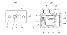
- the further another example of the hydraulic control valve which concerns on this invention is shown, (a) is a top view, (b) is a vertical side view. It is a fragmentary figure which shows the structure of the aperture_diaphragm
- or (i) is a top view which shows the opening shape of the input port which comprises an aperture_diaphragm
- squeeze part by the groove part which the piston provided (a) is a top view, (b) is a vertical side view.
- the hydraulic control valve and the hydraulic control device according to the present invention can be used for a movable body such as a vehicle or an aircraft or various stationary industrial machines.
- the hydraulic pressure of a belt type continuously variable transmission in a vehicle can be applied to a controlling device.
- FIG. 1 One example is schematically shown in FIG.
- the example shown here is an example in which the present invention is applied to a device for supplying hydraulic pressure to a pulley 1 in a belt-type continuously variable transmission.
- the pulley 1 is a primary pulley or a driven side that is conventionally known. Any of the secondary pulleys may be used.
- the configuration of the pulley 1 will be briefly described.
- the pulley 1 is configured by a fixed sheave and a movable sheave that moves back and forth in the axial direction so as to approach and separate from the fixed sheave. ing. Between the fixed sheave and the movable sheave is a groove around which the belt is wound, and the width of the groove is configured to vary widely according to the interval between the sheaves.
- a hydraulic chamber (hydraulic actuator) 2 is provided that generates a load that presses the movable sheave toward the fixed sheave.
- the movable sheave is pushed toward the fixed sheave, and as a result, the groove width becomes narrower and the belt winding radius increases, or the clamping pressure for clamping the belt increases. It is configured to increase.
- a supply valve 5 comprising a balance piston valve corresponding to the hydraulic control valve according to the present invention is provided.
- the oil pressure source 3 may be an oil pump, or may be an oil passage having a line pressure obtained by adjusting the oil pressure generated by the oil pump, or an accumulator that stores oil pressure at a predetermined pressure. There may be.
- the balance piston type valve constituting the supply valve 5 is unique to the present invention. Specifically, the construction of the balance piston type valve will be described.
- the piston 7 is liquid-tight inside the cylinder portion 6 which is a cylindrical portion. It is accommodated so as to move back and forth in the axial direction while maintaining the state. Therefore, a positive pressure chamber 8 is formed on one side (right side in FIG. 1) sandwiching the piston 7 inside the cylinder portion 6, and a back pressure chamber 9 is formed on the opposite side (left side in FIG. 1). Has been.
- a sub chamber 10 is formed adjacent to the positive pressure chamber 8.
- the positive pressure chamber 8 is provided with an input port 11 to which the hydraulic pressure of the hydraulic pressure source 3 described above is supplied and an output port 12 through which the hydraulic pressure flows out from the positive pressure chamber 8.
- the input port 11 is formed in a cylindrical outer peripheral portion of the cylinder portion 6.
- the output port 12 is formed in a portion corresponding to the end plate in the cylinder portion 6, and thus the positive pressure chamber 8 and the sub chamber 10 are configured to communicate with each other through the output port 12.
- a connection port 13 communicating with the hydraulic chamber 2 in the pulley 1 is formed in the sub chamber 10.
- a valve body 14 is provided at the center of the piston 7 on the positive pressure chamber 8 side.
- the valve body 14 is configured to abut against the opening end of the output port 12 on the positive pressure chamber 8 side and close the output port 12.
- a spring 15 that pushes the piston 7 toward the positive pressure chamber 8 is disposed inside the back pressure chamber 9.
- a back pressure port 16 is formed in the back pressure chamber 9 so as to open, and the back pressure port 16 and the input port 11 described above are communicated with each other through a communication path 17.
- a control orifice 18 is provided in the middle of the communication passage 17, and when the pressure in the positive pressure chamber 8 or the back pressure chamber 9 fluctuates, resistance is given to the pressure oil flowing through the communication passage 17 and the positive pressure chamber 8. And a back pressure chamber 9 are caused to generate a pressure difference.
- the control orifice 18 corresponds to the first throttle portion in the present invention, and the control orifice 18 only needs to be configured to generate a pressure difference between the positive pressure chamber 8 and the back pressure chamber 9.
- the first throttling portion in the invention may be configured such that the pipe line constituting the communication passage 17 has a small inner diameter, thereby generating the pressure difference.
- a solenoid valve 19 is provided for selectively communicating the back pressure chamber 9 with a portion whose pressure is lower than the internal pressure.
- the solenoid valve 19 corresponds to the on-off valve in the present invention, is configured to open when energized, and is configured to change, that is, increase in opening according to current. .
- the lower pressure portion than the back pressure chamber 9 is the hydraulic chamber 2 in the pulley 1 described above, and therefore the solenoid valve 19 is communicated with the hydraulic chamber 2.
- the balance piston type valve constituting the supply valve 5 is provided with a throttle portion 20 that provides resistance to the flow of pressure oil flowing into the positive pressure chamber 8.
- the throttle portion 20 corresponds to the second throttle portion in the present invention, and is a portion that partially reduces the flow passage cross-sectional area of the pressure oil toward the positive pressure chamber 8 and resists the flow of pressure oil.
- the position may be any position as long as the pressure oil flowing into the positive pressure chamber 8 passes therethrough. In the example shown in FIG. 1, it is formed between the outer peripheral surface of the piston 7 and the inner peripheral surface of the cylinder portion 6.
- FIG. 2 shows an example of the aperture 20. As shown in FIG.
- the outer diameter of the piston 7 on the tip side is smaller than the inner diameter of the cylinder portion 6, and a gap through which pressure oil can flow is formed between them.
- the position of the input port 11 is opposed to the outer peripheral surface of the piston 7 even when the piston 7 is retracted to a position where the valve element 14 is sufficiently opened away from the output port 12, and the outer periphery of the piston 7. It is set at a position opened in a gap between the surface and the inner peripheral surface of the cylinder portion 6. Therefore, the gap forms a throttle portion 20 that provides resistance to the pressure oil that flows toward the positive pressure chamber 8.
- the throttle unit 20 is configured to have an opening area (channel cross-sectional area) smaller than the opening area (channel cross-sectional area) of the input port 11.
- the length from the input port 11 to the tip of the piston 7 is the length of the throttle portion 20, so that the valve body 14 moves backward together with the piston 7, and the backward movement amount increases.
- the opening amount of the output port 12 is increased, the length of the throttle portion 20 is shortened and the flow resistance by the throttle portion 20 is reduced.
- FIG. 1 shows a state where the supply valve 5 is closed, and the solenoid valve 19 is OFF and closed. Accordingly, since the positive pressure chamber 8 and the back pressure chamber 9 have the same pressure, the piston 7 is pushed toward the positive pressure chamber 8 by the spring 15, and as a result, the valve body 14 is pushed against the opening end of the output port 12. The output port 12 is sealed.
- the balance of the force applied from both sides of the piston 7 in this state is as follows.
- the load that pushes the piston 7 toward the positive pressure chamber 8 is the sum of the load Fs by the spring 15 and the load Fp2 by the hydraulic pressure P2 of the back pressure chamber 9.
- the load Fs by the spring 15 is a load determined by the amount of compression in an initial state in which the spring 15 is incorporated in the cylinder portion 6.
- the area of the piston 7 that receives the back pressure P2 is the cross-sectional area Ap of the piston 7
- the load that pushes the piston 7 and the valve body 14 integrated with the piston 7 toward the back pressure chamber 9 is such that the load Fp1 due to the hydraulic pressure P1 of the positive pressure chamber 8 and the hydraulic pressure P3 of the sub chamber 9 act on the valve body 14. It is the sum with the load Fp3 by doing.
- the hydraulic pressure in the positive pressure chamber 8 is the hydraulic pressure supplied from the input port 11. If this is referred to as upstream pressure, the area where the upstream pressure P1 acts on the piston 7 is from the cross-sectional area Ap to the seal area As by the valve body 14.
- the load Fp1 at which the upstream pressure P1 pushes the piston 7 is a product ((Ap-As) ⁇ P1) of the upstream pressure P1 and the area (Ap-As) on which the upstream pressure P1 acts.
- the sub chamber 9 is a location where the pressure oil flows out from the positive pressure chamber 8, if the hydraulic pressure is temporarily referred to as the downstream pressure P3, the load Fp3 due to the downstream pressure P3 is the product of the downstream pressure P3 and the seal area As described above. (P3 ⁇ As).
- the valve body 14 has the elastic force of the spring 15 and the pressure between the upstream pressure P1 and the downstream pressure P3.
- the valve is kept closed by being pressed against the open end of the output port 12 by the load based on the difference.
- the solenoid valve 19 When the solenoid valve 19 is energized from this closed state, the back pressure chamber 9 is communicated with a low pressure portion such as the hydraulic chamber 2 and the pressure in the back pressure chamber 9 is reduced. In this case, even if the back pressure chamber 9 and the positive pressure chamber 8 are communicated by the communication passage 17, the control passage 18 is provided in the communication passage 17, so that the back pressure chamber 9 and the positive pressure chamber 8 A pressure difference occurs between the two.
- a throttle portion 20 corresponding to a gap between the outer peripheral surface of the piston 7 and the inner peripheral surface of the cylinder portion 6 is formed between the input port 11 and the positive pressure chamber 8. 20, the flow rate is reduced by the flow path resistance, and the increase in the hydraulic pressure of the positive pressure chamber 8 is suppressed.
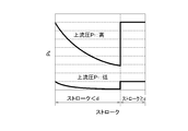
- FIG. 4 shows the relationship between the hydraulic pressure P4 of the positive pressure chamber 8 and the stroke s.
- the hydraulic pressure P4 of the positive pressure chamber 8 acting to move the piston 7 and the valve body 14 in the valve opening direction. Is greatly reduced by the throttle portion 20, so that an increase in the differential pressure for moving the piston 7 and the valve body 14 in the valve opening direction can be suppressed.
- the solenoid valve 19 that acts to allow the hydraulic pressure to flow out from the back pressure chamber 9 is configured to increase the opening according to the current. Therefore, by increasing the current, the hydraulic pressure in the back pressure chamber 9 is increased. Decrease increases. The tendency is shown in FIG. 5. In the state where the opening area of the solenoid valve 19 is small due to the small current, the decrease in the hydraulic pressure in the back pressure chamber 9 is suppressed by the solenoid valve 19. There is little decrease in the hydraulic pressure in the chamber 9, and the differential pressure is also small. When the opening area is increased due to an increase in current, the resistance between the back pressure chamber 9 and the low pressure portion with which the back pressure chamber 9 is communicated decreases, and the degree of decrease in the hydraulic pressure in the back pressure chamber 9 increases. This tendency becomes more prominent as the upstream pressure P1 is higher, and the back pressure P2 is greatly reduced.
- the differential pressure for moving the piston 7 and the valve body 14 in the valve opening direction increases by increasing the current
- the current and the flow rate at the supply valve 5 have a correlation
- the solenoid valve 19 The flow rate at the supply valve 5 can be controlled by the current. More specifically, when the current of the solenoid valve 19 is increased, the differential pressure increases and the flow rate increases in accordance with the current. This state is conceptually shown in FIG.
- the upstream pressure P1 is relatively low, the differential pressure is also small, and therefore the gradient of the increase in flow rate with respect to the increase in current is small. That is, the flow rate gradually increases.
- FIG. 6 shows the flow rate characteristics at the time of high differential pressure when there is no above-mentioned throttle part 20 by broken lines. If the throttle part 20 is not provided, the upstream pressure P1 becomes the hydraulic pressure of the positive pressure chamber 8 as it is, so that the differential pressure or load for moving the piston 7 and the valve body 14 in the valve opening direction increases rapidly, and accordingly. As a result, the flow rate increases rapidly.
- the hydraulic control device even if the hydraulic pressure applied to the input port 11 of the supply valve 5 configured by a balance piston type valve is high, the pressure against the change in current for opening the valve is high.
- the gradient of the change in the oil flow rate can be made gentle. Therefore, regardless of the hydraulic pressure level, the relationship between the flow rate and the current is stable, and the controllability can be improved.
- the throttle can be configured not to act on the pressure oil flowing into the positive pressure chamber 8 when the balance piston valve is fully opened.
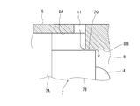
- FIG. 7 shows an example, and the piston 7 in the supply valve 5 which is a balance piston type valve shown here has a base portion 7A equal to the inner diameter of the cylinder portion 6 and a protruding portion 7B having a smaller outer diameter than the base portion 7A. And.
- the protruding portion 7B protrudes from the base portion 7A to the positive pressure chamber 8 side, and is formed in a state in which the above-described valve body 14 protrudes from the central portion of the distal end surface of the protruding portion 7B.
- the positive pressure chamber 8 of the cylinder portion 6 has a large diameter portion 8A in which the base portion 7A of the piston 7 is fitted in a liquid-tight state and is movable back and forth, and an inner diameter smaller than the large diameter portion 8A.
- the protruding portion 7B includes a small-diameter portion 8B into which the protruding portion 7B is loosely fitted, and the small-diameter portion 8B is formed closer to the end plate where the output port 12 is formed than the large-diameter portion 8A.
- a narrowed portion 20 is formed between the outer peripheral surface of the protruding portion 7B and the inner peripheral surface of the small diameter portion 8B in a state where the protruding portion 7B of the piston 7 is fitted to the small diameter portion 8B of the positive pressure chamber 8. Yes.
- a part of the aperture 20 is shown in FIG. Therefore, the outer shape of the protruding portion 7B is smaller than the inner diameter of the small diameter portion 8B by the size of the throttle portion 20.
- the fitting length d between the protruding portion 7B and the small diameter portion 8B in a state where the piston 7 moves forward until the valve body 14 is pressed against the opening end of the output port 12 to be in the closed state is determined by the supply valve 5 Is set to be shorter than the maximum stroke amount c of the piston 7 in the fully open state. That is, when the piston 7 is retracted to the fully open position, the protruding portion 7B is configured to come out of the small diameter portion 8B.
- the input port 11 is formed so as to open to the large diameter portion 8 ⁇ / b> A of the positive pressure chamber 8. Since the other configuration is the same as the configuration shown in FIG. 1, the same reference numerals as those in FIG.
- the back pressure chamber 9 is connected to the hydraulic chamber 2 of the pulley 1 by energizing the solenoid valve 19 communicated with the back pressure chamber 9.
- the hydraulic pressure in the back pressure chamber 9 decreases and a differential pressure is generated between the back pressure chamber 9 and the positive pressure chamber 8.
- the piston 7 and the valve body 14 move in the left direction of FIG.
- FIG. 9 shows an intermediate valve opening state that does not reach full opening, and the protruding portion 7B of the piston 7 is still fitted to the small diameter portion 8B of the cylinder portion 6. That is, the narrowed portion 20 is formed between the protruding portion 7B and the small diameter portion 8B.
- the balance state of the load acting on the piston 7 in this so-called intermediate valve open state is as follows.
- FIG. 11 shows the relationship between the hydraulic pressure P4 of the positive pressure chamber 8 and the strokes s of the piston 7 and the valve body 14 when configured as shown in FIG.
- FIG. 12 shows the relationship between the current of the solenoid valve 19 and the flow rate of the pressure oil.
- the fitting is released.
- the throttle portion 20 is released, and immediately, the hydraulic pressure P4 in the positive pressure chamber 8 increases to a pressure that is substantially equal to the upstream pressure P1. For this reason, the pressure difference between both sides of the piston 7 increases, and the flow rate of the pressure oil increases rapidly. Therefore, when configured as shown in FIG. 7, when it is necessary to rapidly increase the amount of hydraulic pressure supplied to the control target portion such as the hydraulic chamber 2 of the pulley 1, the increase in the hydraulic pressure supply amount is met. Control can be performed.
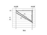
- FIG. 13 shows the relationship between the current of the solenoid valve 19 and the back pressure P2 and the hydraulic pressure P4 of the positive pressure chamber 8, and the current value in the fully closed state in which the valve body 14 closes the output port 12 is expressed as “f”.
- the hydraulic pressure P4 of the positive pressure chamber 8 is the upstream pressure P1
- the back pressure P2 is somewhat lower than that.
- the back pressure P2 gradually decreases according to the opening of the solenoid valve 19, and the pressure oil that opens the output port 12 and flows into the positive pressure chamber 8 while the valve body 14 is opened. Since the flow path resistance at the throttle unit 20 is received, the hydraulic pressure P4 in the positive pressure chamber 8 gradually decreases according to the current.
- the flow rate can be increased or decreased according to the current of the solenoid valve 19, and so-called precise control is possible.
- the flow rate can be rapidly increased to the maximum.
- the current values e, e ', f, and f' are determined by the structure of the balance piston type valve, the dimensions of each part, the structure of the solenoid valve 19, and the like. It is preferable to keep it. Further, since the control is performed by controlling the current of the solenoid valve 19 based on the required amount of oil and hydraulic pressure, the control can be executed using a controller ECU mainly composed of a microcomputer. The calculation of the current value by the controller ECU can be performed by creating a program so as to be performed using a theoretical formula, an experimental formula, or a map.
- the second throttle portion in the present invention will be described.
- the gap between the outer peripheral surface of the piston 7 and the inner peripheral surface of the cylinder portion 6 is defined as the throttle portion 20.
- the second throttle portion may be any portion that can provide flow path resistance to the flow of pressure oil flowing into the positive pressure chamber 8 via the input port 11, and therefore the input port 11. It may be an orifice provided in a flow path connected to the.
- squeeze part of this invention may be comprised so that the opening area by the side of the positive pressure chamber 8 of the input port 11 may change according to the position of the piston 7.
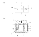
- the example shown in FIGS. 15A and 15B is an example in which the input port 11 is formed in a rectangular shape that is long in the moving direction of the piston 7. That is, the outer diameter of the piston 7 and the inner diameter of the cylinder portion 6 are set substantially equal so that the piston 7 can move back and forth while maintaining a liquid-tight state, and the rectangular input port 11 is connected to the front end of the piston 7. It is formed over the moving range of the edge portion. Therefore, as shown in an enlarged view in FIG.
- FIG. 17 shows an example of the opening shape of the input port 11 that functions as the throttle portion 20 as described above.
- (A) is a triangular shape with the back pressure chamber 9 side as the base, and (b) is this. Is a triangular shape in the opposite direction,
- (c) is a pentagonal shape that is long in the axial direction of the cylinder part 6, and
- (d) is a rhombus that is long in the axial direction of the cylinder part 6.
- (E) is a shape in which round holes with the same inner diameter are arranged in the stroke direction of the piston 7
- (f) is a shape in which the round hole on the back pressure chamber 9 side is relatively large
- (g) is a round hole.
- (H) is a shape in which obtuse triangles are partially overlapped and connected to the bottom side of an acute triangle
- (i) is a combination of long holes and round holes.
- the second throttle portion in the present invention can be formed between the piston and the cylinder portion, so the piston 7 is processed to form the throttle portion 20. May be.
- An example is shown in FIGS. 18 and 19.
- the input port 11 formed in the cylinder portion 6 has a simple circular shape and faces the input port 11 in the outer peripheral portion of the piston 7.
- a groove portion 7C along the axial direction is formed at a location.
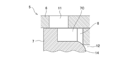
- the groove portion 7 ⁇ / b> C is formed from an intermediate portion in the axial direction of the piston 7 to a tip portion (an end portion where the valve body 14 is formed). Accordingly, as shown in FIG.
- the throttle portion 20 is formed between the edge portion of the groove portion 7 ⁇ / b> C and the edge portion forming the contour of the open end of the input port 11, and the piston 7 is in the valve closing direction.
- the opening area of the throttle portion 20 is small, and when the piston 7 moves backward in the valve opening direction, the groove portion 7C and the input port 11 become large. Since they overlap, the aperture area of the diaphragm 20 becomes large.
- FIG. 20 shows an example thereof.
- the throttle portion 20A is formed on the tip end side of the protrusion 7B. That is, in the positive pressure chamber 8, the corner of the inner peripheral surface of the cylinder portion 6 and the end plate where the output port 12 is formed is larger than the outer diameter of the valve body 14 and larger than the outer diameter of the protruding portion 7B.
- a step portion 6A having a small inner diameter is formed so as to protrude toward the inside of the positive pressure chamber 8.
- the length (width) of the stepped portion 6A in the axial direction is a slight gap between the tip end surface of the projecting portion 7B, that is, the throttle, even when the piston 7 is advanced to the fully closed state.
- the dimension is set so that the portion 20A is formed. Since the pressure oil flowing into the positive pressure chamber 8 from the input port 11 passes through the throttle portion 20A, the hydraulic pressure is reduced by the flow path resistance, and the flow rate of the pressure oil is reduced. When the piston 7 moves backward in the valve opening direction, the gap between the stepped portion 6A and the distal end surface of the protruding portion 7B is increased, so that the opening area of the throttle portion 20A increases, and thus the throttle portion 20A having variable characteristics is obtained.
- the second diaphragm portion according to the present invention has a fixed aperture area and a fixed diaphragm characteristic. There may be.
- the area of the opening end of the input port 11 with respect to the positive pressure chamber 8 is made narrower than the flow area on the upstream side thereof, and the narrow portion 11A is used as the second throttle portion in the present invention. Good.
- the narrow portion 11A is used as the second throttle portion in the present invention. Good.
- a through hole 7 d extending from the outer peripheral surface to the end surface on the positive pressure chamber 8 side is formed in the piston 7, and the cross-sectional area of the through hole 7 d is determined from the opening area of the input port 11.
- the through hole 7d may be set to be small and serve as the second throttle portion in the present invention. That is, the through hole 7 d is formed at a position that opens toward the input port 11 over the entire movement range of the piston 7, and the pressure oil supplied to the input port 11 is narrower than the input port 11. By passing through the through-hole 7d of the area, the pressure and flow rate are reduced by the throttling action.
- the area of the flow path of the pressure oil supplied toward the positive pressure chamber 8 is constant regardless of the stroke amount of the piston 7. Is fixed.
Landscapes
- Engineering & Computer Science (AREA)
- Physics & Mathematics (AREA)
- Fluid Mechanics (AREA)
- Mechanical Engineering (AREA)
- General Engineering & Computer Science (AREA)
- Fluid-Driven Valves (AREA)
- Control Of Transmission Device (AREA)
- Magnetically Actuated Valves (AREA)
Abstract
L'invention porte sur une soupape de commande hydraulique conçue de telle sorte qu'une chambre de pression positive, dans laquelle débouchent un orifice d'entrée et un orifice de sortie, et une chambre de contrepression sont respectivement formées sur un premier côté et sur l'autre côté d'un piston qui se déplace vers l'avant et vers l'arrière à l'intérieur d'un cylindre dans la direction axiale. Un corps de soupape servant à ouvrir et à fermer l'orifice de sortie est disposé de façon à être relié au piston. La chambre de pression positive et la chambre de contrepression sont reliées l'une à l'autre à travers une première section de réduction de débit qui produit une différence de pression entre la chambre de pression positive et la chambre de contrepression. Une soupape d'ouverture/fermeture, destinée à relier sélectivement la chambre de contrepression à une partie ayant une pression inférieure à la chambre de contrepression, est reliée à la soupape de commande hydraulique. L'orifice d'entrée est relié à une section à haute pression et l'orifice de sortie est relié à une section à basse pression ayant une pression inférieure à celle de la section à haute pression. La soupape de commande hydraulique est également munie d'une seconde section de réduction de débit destinée à limiter le débit d'huile mise sous pression qui s'écoule dans la chambre de pression positive à travers l'orifice d'entrée.
Priority Applications (2)
| Application Number | Priority Date | Filing Date | Title |
|---|---|---|---|
| PCT/JP2012/060606 WO2013157125A1 (fr) | 2012-04-19 | 2012-04-19 | Soupape de commande hydraulique et dispositif de commande hydraulique |
| JP2014511048A JP5733472B2 (ja) | 2012-04-19 | 2012-04-19 | 油圧制御バルブおよび油圧制御装置 |
Applications Claiming Priority (1)
| Application Number | Priority Date | Filing Date | Title |
|---|---|---|---|
| PCT/JP2012/060606 WO2013157125A1 (fr) | 2012-04-19 | 2012-04-19 | Soupape de commande hydraulique et dispositif de commande hydraulique |
Publications (1)
| Publication Number | Publication Date |
|---|---|
| WO2013157125A1 true WO2013157125A1 (fr) | 2013-10-24 |
Family
ID=49383107
Family Applications (1)
| Application Number | Title | Priority Date | Filing Date |
|---|---|---|---|
| PCT/JP2012/060606 Ceased WO2013157125A1 (fr) | 2012-04-19 | 2012-04-19 | Soupape de commande hydraulique et dispositif de commande hydraulique |
Country Status (2)
| Country | Link |
|---|---|
| JP (1) | JP5733472B2 (fr) |
| WO (1) | WO2013157125A1 (fr) |
Cited By (3)
| Publication number | Priority date | Publication date | Assignee | Title |
|---|---|---|---|---|
| CN113244974A (zh) * | 2021-04-30 | 2021-08-13 | 重庆微浪自动化设备有限公司 | 样品自动化处理平台及样品处理方法 |
| CN114088146A (zh) * | 2021-11-12 | 2022-02-25 | 西安迈象能源科技有限公司 | 一种气体流量检测控制集成阀岛装置 |
| CN116398680A (zh) * | 2023-04-27 | 2023-07-07 | 中国中材国际工程股份有限公司 | 一种液压气弹簧式恒流量调节阀 |
Families Citing this family (1)
| Publication number | Priority date | Publication date | Assignee | Title |
|---|---|---|---|---|
| US5571268A (en) | 1993-12-16 | 1996-11-05 | A.W. Chesterton Company | Universal split mechanical seal |
Citations (3)
| Publication number | Priority date | Publication date | Assignee | Title |
|---|---|---|---|---|
| JP2003246565A (ja) * | 2002-02-21 | 2003-09-02 | Oil Drive Kogyo Kk | 省エネルギー型油圧昇降装置 |
| JP2011163393A (ja) * | 2010-02-05 | 2011-08-25 | Toyota Motor Corp | 油圧制御装置およびベルト式無段変速機の制御装置 |
| JP2011163508A (ja) * | 2010-02-12 | 2011-08-25 | Toyota Motor Corp | 油圧制御装置 |
-
2012
- 2012-04-19 WO PCT/JP2012/060606 patent/WO2013157125A1/fr not_active Ceased
- 2012-04-19 JP JP2014511048A patent/JP5733472B2/ja not_active Expired - Fee Related
Patent Citations (3)
| Publication number | Priority date | Publication date | Assignee | Title |
|---|---|---|---|---|
| JP2003246565A (ja) * | 2002-02-21 | 2003-09-02 | Oil Drive Kogyo Kk | 省エネルギー型油圧昇降装置 |
| JP2011163393A (ja) * | 2010-02-05 | 2011-08-25 | Toyota Motor Corp | 油圧制御装置およびベルト式無段変速機の制御装置 |
| JP2011163508A (ja) * | 2010-02-12 | 2011-08-25 | Toyota Motor Corp | 油圧制御装置 |
Cited By (5)
| Publication number | Priority date | Publication date | Assignee | Title |
|---|---|---|---|---|
| CN113244974A (zh) * | 2021-04-30 | 2021-08-13 | 重庆微浪自动化设备有限公司 | 样品自动化处理平台及样品处理方法 |
| CN113244974B (zh) * | 2021-04-30 | 2022-12-30 | 重庆微浪自动化设备有限公司 | 样品自动化处理平台及样品处理方法 |
| CN114088146A (zh) * | 2021-11-12 | 2022-02-25 | 西安迈象能源科技有限公司 | 一种气体流量检测控制集成阀岛装置 |
| CN114088146B (zh) * | 2021-11-12 | 2023-07-07 | 西安迈象能源科技有限公司 | 一种气体流量检测控制集成阀岛装置 |
| CN116398680A (zh) * | 2023-04-27 | 2023-07-07 | 中国中材国际工程股份有限公司 | 一种液压气弹簧式恒流量调节阀 |
Also Published As
| Publication number | Publication date |
|---|---|
| JPWO2013157125A1 (ja) | 2015-12-21 |
| JP5733472B2 (ja) | 2015-06-10 |
Similar Documents
| Publication | Publication Date | Title |
|---|---|---|
| JP5592641B2 (ja) | 電気油圧ポペットパイロット弁によって操作されるポペット弁 | |
| JP5461986B2 (ja) | 双方向力フィードバックポペット弁 | |
| US20070210270A1 (en) | Pilot operated valve with a pressure balanced poppet | |
| JPWO2012118211A1 (ja) | 減衰力可変ダンパ | |
| JP5733472B2 (ja) | 油圧制御バルブおよび油圧制御装置 | |
| WO2007149192A2 (fr) | Soupape à champignon | |
| JP2011163508A (ja) | 油圧制御装置 | |
| JP6070830B2 (ja) | 油圧制御バルブおよび油圧制御装置 | |
| CA2510198A1 (fr) | Robinet de reglage automatique du debit | |
| US20070157980A1 (en) | Pilot operated control valve having a two stage poppet | |
| JP2008501917A (ja) | 電気的に作動可能なバルブ | |
| EP0640047B1 (fr) | Vanne de regulation proportionnelle avec compensation de pression | |
| JP3536243B2 (ja) | 油圧供給装置 | |
| JP2013221614A (ja) | 油圧制御バルブおよび油圧制御装置 | |
| JP5655960B2 (ja) | 油圧制御回路 | |
| JP5704629B2 (ja) | 吸振器を備えた比例ポペット型二段式高速電磁弁 | |
| CN212717427U (zh) | 一种变功率阀组、变功率控制装置及液压系统 | |
| JP5644487B2 (ja) | 油圧制御弁 | |
| JP3415512B2 (ja) | 弁装置 | |
| JPH0433046B2 (fr) | ||
| RU91610U1 (ru) | Клапан для управления давлением в гидравлических устройствах | |
| JPS61208109A (ja) | 減圧弁 | |
| US10352318B2 (en) | Hydraulic regulating device | |
| RU79161U1 (ru) | Клапанное устройство | |
| JPS608383B2 (ja) | カウンタバランス弁 |
Legal Events
| Date | Code | Title | Description |
|---|---|---|---|
| 121 | Ep: the epo has been informed by wipo that ep was designated in this application |
Ref document number: 12874865 Country of ref document: EP Kind code of ref document: A1 |
|
| ENP | Entry into the national phase |
Ref document number: 2014511048 Country of ref document: JP Kind code of ref document: A |
|
| NENP | Non-entry into the national phase |
Ref country code: DE |
|
| 122 | Ep: pct application non-entry in european phase |
Ref document number: 12874865 Country of ref document: EP Kind code of ref document: A1 |