WO2013157199A1 - Palplanche d'acier, paroi en palplanches d'acier formée à partir de palplanches d'acier, et procédé de fabrication de palplanche d'acier - Google Patents
Palplanche d'acier, paroi en palplanches d'acier formée à partir de palplanches d'acier, et procédé de fabrication de palplanche d'acier Download PDFInfo
- Publication number
- WO2013157199A1 WO2013157199A1 PCT/JP2013/001833 JP2013001833W WO2013157199A1 WO 2013157199 A1 WO2013157199 A1 WO 2013157199A1 JP 2013001833 W JP2013001833 W JP 2013001833W WO 2013157199 A1 WO2013157199 A1 WO 2013157199A1
- Authority
- WO
- WIPO (PCT)
- Prior art keywords
- steel sheet
- sheet pile
- shaped
- split
- base member
- Prior art date
- Legal status (The legal status is an assumption and is not a legal conclusion. Google has not performed a legal analysis and makes no representation as to the accuracy of the status listed.)
- Ceased
Links
Images






Classifications
-
- B—PERFORMING OPERATIONS; TRANSPORTING
- B21—MECHANICAL METAL-WORKING WITHOUT ESSENTIALLY REMOVING MATERIAL; PUNCHING METAL
- B21B—ROLLING OF METAL
- B21B1/00—Metal-rolling methods or mills for making semi-finished products of solid or profiled cross-section; Sequence of operations in milling trains; Layout of rolling-mill plant, e.g. grouping of stands; Succession of passes or of sectional pass alternations
- B21B1/08—Metal-rolling methods or mills for making semi-finished products of solid or profiled cross-section; Sequence of operations in milling trains; Layout of rolling-mill plant, e.g. grouping of stands; Succession of passes or of sectional pass alternations for rolling structural sections, i.e. work of special cross-section, e.g. angle steel
- B21B1/082—Piling sections having lateral edges specially adapted for interlocking with each other in order to build a wall
-
- E—FIXED CONSTRUCTIONS
- E02—HYDRAULIC ENGINEERING; FOUNDATIONS; SOIL SHIFTING
- E02D—FOUNDATIONS; EXCAVATIONS; EMBANKMENTS; UNDERGROUND OR UNDERWATER STRUCTURES
- E02D5/00—Bulkheads, piles, or other structural elements specially adapted to foundation engineering
- E02D5/02—Sheet piles or sheet pile bulkheads
- E02D5/03—Prefabricated parts, e.g. composite sheet piles
- E02D5/04—Prefabricated parts, e.g. composite sheet piles made of steel
Definitions
- the present invention relates to a steel sheet pile, a steel sheet pile wall formed by the steel sheet pile, and a method for manufacturing the steel sheet pile.
- a hat-shaped steel sheet pile as shown in Patent Document 1 is known as a steel sheet pile having a large cross section.
- Patent Document 2 there is a method in which two Z-shaped steel sheet pile joint portions are fitted in advance and connected and fixed by caulking or welding to form a symmetrical hat cross-sectional shape.
- hat-shaped steel sheet piles and Z-shaped steel sheet piles are usually formed by hot rolling, the size of the steel sheet piles, such as the number of models and the width of the steel sheet piles, is limited due to restrictions on factory facilities. For this reason, it is not necessarily the optimal and rational cross-sectional shape for the structural performance required at each construction site. In other words, in the case of a steel sheet pile formed by hot rolling, selecting an existing size closer to the required structural performance is performed.
- Some steel sheet piles are formed by cold working (bending), and such steel sheet piles have a relatively high degree of freedom in adjusting their size, and the structural performance required for each construction site.
- the joint portion of the steel sheet pile formed by cold working (bending) is significantly inferior in strength and processing accuracy as compared with the joint portion of the steel sheet pile formed by hot rolling. For this reason, there is a concern that construction difficulties may occur, and sufficient structural performance may not be exhibited due to joint damage during construction.
- the present invention has been made to solve such a problem, and has a high degree of freedom in size adjustment, a steel sheet pile having a high strength and accuracy of the joint, a manufacturing method thereof, and a steel sheet pile wall formed by the steel sheet pile.
- the purpose is to provide.
- a steel sheet pile according to the present invention includes a steel sheet pile split member having at least a joint part obtained by cutting a steel sheet pile formed by hot rolling, and a base without a joint part produced by rolling or bending. It is formed by joining members, and the overall shape is a shape provided with arm portions extending outward and having joint portions at the ends at both ends of a substantially U-shaped portion in an axially orthogonal cross section. It is.
- molded by the said hot rolling is a U-shaped steel sheet pile.
- the steel sheet pile dividing member is an L-shaped U-shaped steel sheet pile divided first obtained by cutting a web root which is a shoulder portion on one side of the U-shaped steel sheet pile. It consists of one member and a linear U-shaped steel sheet pile divided second member, and the base member is an L-shaped base member.
- segmentation member is the L-shaped U-shaped steel sheet pile division
- the length between the joint portions on both sides is L 1
- the length of the narrowest part in the U-shaped portion is L 2. Then, the relationship 1/6 ⁇ L 1 ⁇ L 2 ⁇ 1/2 ⁇ L 1 is satisfied.
- the steel sheet pile wall according to the present invention is formed by connecting the joint portions of the steel sheet piles according to any one of the above (1) to (6) and driving them into the ground.
- a method for manufacturing a steel sheet pile according to the present invention includes a steel sheet pile split member manufacturing step of manufacturing a steel sheet pile split first member having a joint at an end by cutting a steel sheet pile formed by hot rolling, It comprises a base member manufacturing process for manufacturing a base member having no joint part by rolling and bending, and a steel sheet pile split member joining process for joining the steel sheet pile split members to both ends of the base member.
- molded by the said hot rolling is a U-shaped steel sheet pile.
- the steel sheet pile dividing member manufacturing step cuts the web root which is a shoulder portion on one side of the U-shaped steel sheet pile, thereby dividing the L-shaped U-shaped steel sheet pile.
- 1 member and a linear U-shaped steel sheet pile split second member are manufactured, the base member manufacturing step manufactures an L-shaped base member, and the steel sheet pile split member joining step is substantially an axial cross section.
- the U-shaped steel sheet pile split first member and the U-shaped steel are formed at both ends of the L-shaped base member so as to have a shape including an arm portion extending outwardly at both ends of the U-shape and having a joint at the tip.
- the sheet pile split second member is joined.
- the steel sheet pile dividing member manufacturing step is performed by cutting a web root which is a shoulder portion on one side of the U-shaped steel sheet pile and dividing the L-shaped U-shaped steel sheet pile.
- 1 member and a linear U-shaped steel sheet pile split second member are manufactured, the base member manufacturing step manufactures a J-shaped base member, and the steel sheet pile split member joining step is substantially an axial cross section.
- the U-shaped steel sheet pile split first member and the U-shaped steel are formed at both ends of the J-shaped base member so as to have a shape including an arm portion extending outwardly at both ends of the U-shape and having a joint at the tip.
- the sheet pile split second member is joined.
- the steel sheet pile according to the present invention includes a steel sheet pile split member having at least a joint portion obtained by cutting a steel sheet pile formed by hot rolling, and a base member without a joint portion manufactured by rolling or bending. Since the overall shape is a shape provided with arm portions that extend outward and have joint portions at the ends at both ends of a substantially U-shaped U-shaped portion in an axially orthogonal cross section. It is a steel sheet pile having a high degree of freedom and maintaining the strength and accuracy of the joint, and good workability can be obtained.
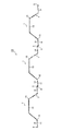
- FIG. 1 is an explanatory diagram of a steel sheet pile according to an embodiment of the present invention.
- Drawing 2 is an explanatory view of other forms of the steel sheet pile concerning one embodiment of the present invention.
- Drawing 3 is an explanatory view of other forms of the steel sheet pile concerning one embodiment of the present invention.
- Drawing 4 is an explanatory view of other forms of the steel sheet pile concerning one embodiment of the present invention.
- Drawing 5 is an explanatory view of other forms of the steel sheet pile concerning one embodiment of the present invention.
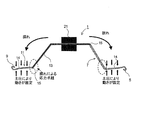
- FIG. 6 is an explanatory view for explaining the operation of another embodiment of the steel sheet pile according to the embodiment of the present invention.
- FIG. 7 is explanatory drawing explaining the effect
- FIG. 8 is an explanatory diagram of a steel sheet pile wall formed by a steel sheet pile according to an embodiment of the present invention.
- FIG. 9 is an explanatory diagram of a steel sheet pile wall formed by another aspect of the steel sheet pile according to the embodiment of the present invention.
- FIG. 10 is an explanatory diagram of a steel sheet pile according to another embodiment of the present invention.
- FIG. 11 is an explanatory diagram of a steel sheet pile according to another aspect of another embodiment of the present invention.
- FIG. 12 is an explanatory diagram of a steel sheet pile according to another aspect of another embodiment of the present invention.
- FIG. 13 is an explanatory diagram of a steel sheet pile wall formed by steel sheet piles according to another embodiment of the present invention.
- FIG. 14 is an explanatory view of the steel sheet pile wall formed of the steel sheet pile of other modes concerning other embodiments of the present invention.
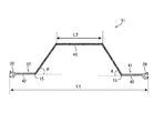
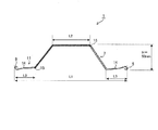
- FIG. 15 is an explanatory diagram of a steel sheet pile according to the first embodiment of the present invention.
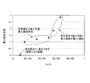
- FIG. 16 is an explanatory diagram for explaining the effect of the steel sheet pile according to the first embodiment of the present invention.
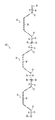
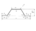
- FIG. 17 is an explanatory diagram of a steel sheet pile according to Embodiment 2 of the present invention.
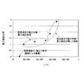
- FIG. 18 is an explanatory diagram for explaining the effect of the steel sheet pile according to the second embodiment of the present invention.
- FIG. 19 is an explanatory diagram illustrating a specific example of a steel sheet pile according to the second embodiment of the present invention.
- FIG. 20 is an explanatory view illustrating another specific example of the steel sheet pile according to the second embodiment of the present invention.
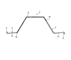
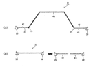
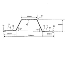
- a steel sheet pile 1 As shown in FIG. 1 (a), a steel sheet pile 1 according to an embodiment of the present invention has a shoulder on one side of a U-shaped steel sheet pile 3 (see FIG. 1 (b)) formed by hot rolling.
- a first U-shaped steel sheet pile split first member 7 having a first joint portion 5 at an end portion obtained by cutting a web root) and a second joint portion 9 at an end portion, and a linear U shape.
- the steel sheet pile divided second member 11 is welded and joined to an end portion of a substantially L-shaped base member 13 having no joint portion manufactured by rolling or bending.
- the overall shape of the steel sheet pile 1 has arm portions 14 extending outward at both ends of the substantially U-shaped portion in an axially orthogonal cross section, and the first joint portion 5 and the second joint portion 9 are provided at the ends of the arm portion 14. Is provided.
- the U-shaped steel sheet pile 3 may be an existing size or may be other than the existing size.
- the U-shaped steel sheet pile 3 is manufactured by hot rolling, and the first joint portion 5 and the second joint portion 9 are made with high accuracy. Therefore, the joint part of the steel sheet pile 1 becomes highly reliable by using the U-shaped steel sheet pile split first member 7 and the U-shaped steel sheet pile split second member 11 obtained by cutting the U-shaped steel sheet pile 3. , It is excellent in enforceability when fitting and placing the joint part.
- the L-shaped base member 13 is manufactured by rolling or bending. Since the L-shaped base member 13 does not have a joint portion, the shape is simple, and compared with the steel sheet pile shape having a joint, forming is much easier both in hot rolling and in cold bending. Therefore, various sizes can be molded at low cost. Therefore, the L-shaped base member 13 can freely and easily change its width and plate thickness. As a result, the steel sheet pile 1 using the L-shaped base member 13 can have an optimal cross section for the structural performance required at each construction site.
- the joint portion has high accuracy and high reliability, and the L-shaped base member 13 can be easily formed in an optimum cross section corresponding to each operation site. Therefore, it is a steel sheet pile having a high degree of freedom in size adjustment and maintaining the strength and accuracy of the joint, and good workability can be obtained. And since it can manufacture easily, manufacturing cost can also be reduced. That is, the steel sheet pile 1 of the present embodiment has a high degree of freedom in size, so that (1) an optimum cross section can be provided for the structural performance required for each construction site, and (2) a steel sheet pile joint. The two points of obtaining good workability by maintaining the strength and accuracy of the above are compatible. And compared with the case where it is going to manufacture the steel sheet pile of the same cross section as the steel sheet pile 1 of this Embodiment by hot rolling, manufacture with the capital investment amount small to each step
- the steel sheet pile 1 of this Embodiment is a U-shaped steel sheet pile division
- the U-shaped steel sheet pile 3 is cut at the shoulders on both sides thereof to obtain two linear joint members, and those that are joined to both ends of the substantially U-shaped base member are excluded. It is not a thing.
- the steel sheet pile 1 as described above can be easily manufactured, for example, by a manufacturing method having the following steps.
- the U-shaped steel sheet pile division first member 7 and the U-shaped steel sheet pile division second member 11 are arranged at both ends of the L-shaped base member 13 so as to have a shape having arm portions 14 extending outward at both ends of the U-shaped steel sheet pile. Join.
- the steel sheet pile 1 according to the present embodiment (1) can provide the optimum cross section for the structural performance required for each construction site, and (2) the strength and precision of the steel sheet pile joint. While being able to achieve both of the two points of obtaining good workability, it can be manufactured by an extremely simple manufacturing method as described above.
- the joining of the U-shaped steel sheet pile split first member 7 and the U-shaped steel sheet pile split second member 11 and the L-shaped base member 13 is joined via a weld joint 15 by welding.
- other joining methods such as bolt joining may be used.
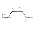
- an example of a substantially L-shaped base member 13 is shown as the base member, but a substantially J-shaped base member 17 may be used as shown in FIG.
- the J-shaped base member 17 is slightly more difficult to form than the L-shaped base member 13, but has an advantage that the height as a steel sheet pile can be set high and a larger cross-sectional performance can be obtained. is there.
- the U-shaped steel sheet pile split second member 11 is grounded at three points with the second joint portion 9. In this way, by making the shape to be grounded at three points, the stability when grounded is increased, and damage due to impacts during transportation, etc., and collapse when stacked can be prevented.
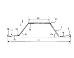
- the length L 2 of the narrowest part of the U-shaped part is set to 1/6 ⁇ L 1 ⁇ L 2 ⁇ 1/2 ⁇ L 1 . It is demonstrated in the Example mentioned later that enforcement stability increases by setting it as such a shape.
- the web angle ⁇ c to which the straight U-shaped steel sheet pile split second member 11 is attached exceeds the web angle ⁇ u (see FIG. 5) on which the substantially L-shaped U-shaped steel sheet pile split first member 7 is attached, and is preferably 90 ° or less.
- the web angle ⁇ c is set to 90 ° or less because when the web angle ⁇ c exceeds 90 °, the blockage at the corner portion (bent portion) of the steel sheet pile 1 is increased, and the penetration resistance during construction is increased. It was made to fall below this. Thereby, the enforcement property of the steel sheet pile 1 increases.
- the web angle ⁇ c to which the linear U-shaped steel sheet pile split second member 11 is attached (see FIG. 5). ) Is less than the web angle ⁇ u (see FIG. 5) on which the substantially L-shaped U-shaped steel sheet pile split first member 7 is attached and is equal to or greater than TAN ⁇ 1 (L 1 / L 2 ) (rad). Is preferred.
- the reason is as follows. When the gripping locations 21 of the steel sheet pile construction machine are two points on the web portion, a force that sways in the direction perpendicular to the web around the gripping locations 21 is likely to occur.
- the web angle ⁇ c (see FIG. 5) to which the linear U-shaped steel sheet pile split second member 11 is attached is the web angle ⁇ u to which the substantially L-shaped U-shaped steel sheet pile split first member 7 is attached.
- the stress acting on the joint was made smaller than (see FIG. 5).
- the web angle ⁇ c is set to TAN -1 (L 1 / L 2 ) (rad) or more. If the web angle is reduced, the torsional rigidity of the steel sheet pile cross section may be reduced, and problems such as buckling failure may occur. It is to increase.
- the steel sheet pile wall 23 can be constructed
- FIG. 8 uses the L-shaped base member 13
- FIG. 9 uses the J-shaped base member 17. Since the steel sheet pile 1 which concerns on this Embodiment is excellent in the intensity
- the base member (L-shaped base member 13, J-type base member 17) in the steel sheet pile 1 has an optimal cross section for the structural performance required for each construction site, such a steel sheet pile 1
- the steel sheet pile wall 23 formed by the above has an optimum cross section required by the enforcement site.
- the U-shaped steel sheet pile 3 is used, but this embodiment uses a straight steel sheet pile.
- the steel sheet pile 31 of this Embodiment has the 1st joint part 35 and the 2nd joint part 39 which have the 1st joint part 35 obtained by cut
- the steel sheet pile 31 according to the present embodiment has an overall shape substantially in an axially orthogonal cross section by joining the straight steel sheet pile divided first member 37 and the straight steel sheet pile divided second member 41 to both ends of the U-shaped base member 43, respectively.
- the U-shaped U-shaped portion has arm portions 42 that extend outward at both ends, and the end portion of the arm portion 42 has a first joint portion 35 and a second joint portion 39.
- the straight steel sheet pile 33 may be an existing size or may be other than the existing size.
- the straight steel sheet pile 33 is manufactured by hot rolling, and the first joint part 35 and the second joint part 39 which are joint parts thereof are made with high accuracy. Therefore, the joint part of the steel sheet pile 31 becomes a reliable thing by utilizing the linear steel sheet pile division
- the U-shaped base member 43 is manufactured by rolling or bending. Since the U-shaped base member 43 does not have a joint portion, the shape is simple, and compared to a steel sheet pile shape having a joint, forming is much easier in both hot rolling and cold bending.
- the U-shaped base member 43 can freely and easily change its width and plate thickness.
- the steel sheet pile 31 of the present embodiment using the U-shaped base member 43 has an optimal cross section for the structural performance required at each construction site. Note that the U-shaped base member 43 is much easier to form in hot rolling and cold bending than the steel sheet pile shape having a joint, and can be formed into various sizes at low cost. Needless to say.
- the steel sheet pile 31 according to the present embodiment has a highly accurate and reliable joint portion, and the base member can have an optimum cross section corresponding to each operation site. It is a steel sheet pile having a high degree of freedom and maintaining the strength and accuracy of the joint, and good workability can be obtained. And since it can manufacture easily, manufacturing cost can also be reduced. That is, the steel sheet pile 31 of the present embodiment has a high degree of freedom in size, so that (1) an optimum cross section can be provided for the structural performance required for each construction site, and (2) a steel sheet pile joint. It is compatible with the two points of obtaining good workability by maintaining the strength and accuracy. And compared with the case where the steel sheet pile of the same cross section as the steel sheet pile 31 of this Embodiment is manufactured by hot rolling, manufacture with the capital investment amount with few steps
- the steel sheet pile 31 as described above can be easily manufactured by the following manufacturing method, for example.
- the manufacturing method of the steel sheet pile 31 of this Embodiment is the steel sheet pile which manufactures the linear steel sheet pile division
- Split member manufacturing process base member manufacturing process for manufacturing U-shaped base member 43 having no joint part by rolling and bending, straight steel sheet pile split first member 37 and straight steel sheet pile split at both ends of the base member
- a steel sheet pile split member joining step that joins the second member 41, and the steel sheet pile split member joining step has a shape including arm portions 42 extending outward at both ends of a substantially U shape in an axially orthogonal cross section.
- the straight steel sheet pile split first member 37 and the straight steel sheet pile split second member 41 are joined to both ends of the U-shaped base member 43.
- the straight steel sheet pile split first member 37 and the straight steel sheet pile split second member 41 and the U-shaped base member 43 are joined via the weld joint 15 by welding.
- Other joining methods for example, bolt joining may be used.
- an example of a substantially U-shaped base member 43 is shown as the base member, but a substantially hat-shaped base member 45 may be used as shown in FIG.
- the length L 2 of the narrowest part of the U-shaped portion is set to 1/6 ⁇ L 1 ⁇ L 2 ⁇ 1/2 ⁇ L 1 .
- the steel sheet pile wall 47 can be constructed
- FIG. 13 shows the U-shaped base member 43 as the base member
- FIG. 14 shows the hat-type base member 45 as the base member. Since the steel sheet pile 31 according to the present embodiment is excellent in the strength and accuracy of the first joint portion 35 and the second joint portion 39, the steel sheet pile wall 47 formed by the steel sheet pile 31 has the accuracy and strength of the connecting portion. Excellent.
- the base member (U-shaped base member 43, hat-shaped base member 45) in the steel sheet pile 31 has an optimal cross section for the structural performance required for each construction site, such a steel sheet pile 1
- the steel sheet pile wall 47 formed by the above has an optimum cross section required by the enforcement site.
- U-shaped steel sheet piles and straight steel sheet piles have been described as examples of steel sheet piles manufactured by hot rolling. This is because these two types of steel sheet piles are manufactured as many types as existing ones and the possibility of use is high.
- steel sheet piles of other shapes manufactured by hot rolling are used. The case where the joint portion is divided and used is not excluded.
- Other steel sheet piles manufactured by hot rolling include, for example, hat-shaped steel sheet piles and Z-shaped steel sheet piles, but the present invention also includes the use of joint portions of these steel sheet piles and other shapes. It is a waste.
- FIG. 15 shows the shape of the model
- Table 1 shows the model case (length of each part, etc.).
- the overall length L 1 of the steel sheet pile 1 (length between both stud ends) was constant at 150 mm, the site of narrowest in the U-shaped portion of the length L 2 15 Changed to ⁇ 100mm. Then arm length L 3 are all cases steel sheet pile 1 also was the most width length half the length of L 2 of the narrow portion in the U-shaped portion. The height H of the steel sheet pile 1 was constant at 50 mm. The construction length was 1000 mm.
- the vertical axis represents the penetration resistance ratio with respect to case 2 (penetration resistance when the penetration resistance of case 2 is 1)
- the horizontal axis represents L 2 / L 1 .
- the length L 2 of the site was conducted model experiments to investigate the range of the optimum.
- FIG. 17 shows the shape of the model, and Table 2 shows the model case (length of each part, etc.).
- the length of the steel sheet pile L 1 (the length between both joint ends) was constant at 150 mm, and the U-shaped part length L 2 was varied from 15 to 100 mm.
- the length L 3 of the straight steel sheet pile division at that time was 1/2 the length L 2 of the narrowest part of the U-shaped part in each case.
- the height H of the steel sheet pile 31 was constant at 50 mm.
- the construction length was 1000 mm.
- the vertical axis represents the penetration resistance ratio with respect to case 2 (penetration resistance when the penetration resistance of case 2 is 1)
- the horizontal axis represents L 2 / L 1 .
- the base member shown in FIG. 19 has a U shape
- the base member shown in FIG. 20 has a hat shape.
Landscapes
- Engineering & Computer Science (AREA)
- Structural Engineering (AREA)
- General Life Sciences & Earth Sciences (AREA)
- Composite Materials (AREA)
- Chemical & Material Sciences (AREA)
- Life Sciences & Earth Sciences (AREA)
- Mechanical Engineering (AREA)
- Mining & Mineral Resources (AREA)
- Paleontology (AREA)
- Civil Engineering (AREA)
- General Engineering & Computer Science (AREA)
- Bulkheads Adapted To Foundation Construction (AREA)
- Metal Rolling (AREA)
Applications Claiming Priority (2)
| Application Number | Priority Date | Filing Date | Title |
|---|---|---|---|
| JP2012093325A JP5966553B2 (ja) | 2012-04-16 | 2012-04-16 | 鋼矢板、該鋼矢板によって形成される鋼矢板壁、鋼矢板の製造方法 |
| JP2012-093325 | 2012-04-16 |
Publications (1)
| Publication Number | Publication Date |
|---|---|
| WO2013157199A1 true WO2013157199A1 (fr) | 2013-10-24 |
Family
ID=49383174
Family Applications (1)
| Application Number | Title | Priority Date | Filing Date |
|---|---|---|---|
| PCT/JP2013/001833 Ceased WO2013157199A1 (fr) | 2012-04-16 | 2013-03-18 | Palplanche d'acier, paroi en palplanches d'acier formée à partir de palplanches d'acier, et procédé de fabrication de palplanche d'acier |
Country Status (2)
| Country | Link |
|---|---|
| JP (1) | JP5966553B2 (fr) |
| WO (1) | WO2013157199A1 (fr) |
Families Citing this family (2)
| Publication number | Priority date | Publication date | Assignee | Title |
|---|---|---|---|---|
| JP6343985B2 (ja) * | 2014-03-17 | 2018-06-20 | 新日鐵住金株式会社 | 防護層を有する鋼製部材及び基礎構造物 |
| WO2020045119A1 (fr) | 2018-08-31 | 2020-03-05 | 日本製鉄株式会社 | Palplanche d'acier en forme de chapeau |
Citations (7)
| Publication number | Priority date | Publication date | Assignee | Title |
|---|---|---|---|---|
| JPS62170610A (ja) * | 1986-01-20 | 1987-07-27 | Nippon Steel Corp | 継手部の回転・自由度に優れた鋼矢板 |
| JPS6371241U (fr) * | 1986-10-22 | 1988-05-13 | ||
| JPS63141232U (fr) * | 1987-03-06 | 1988-09-16 | ||
| JPH09221746A (ja) * | 1996-02-20 | 1997-08-26 | Sumitomo Metal Ind Ltd | 地中壁体構築用鋼製パネル |
| JP2006037580A (ja) * | 2004-07-29 | 2006-02-09 | Nippon Steel Corp | 鋼製エレメントの継ぎ手構造および鋼製矢板 |
| JP2009155896A (ja) * | 2007-12-26 | 2009-07-16 | Nippon Steel Corp | ハット形鋼矢板 |
| JP2011140867A (ja) * | 2009-12-11 | 2011-07-21 | Jfe Steel Corp | Z形鋼矢板 |
-
2012
- 2012-04-16 JP JP2012093325A patent/JP5966553B2/ja active Active
-
2013
- 2013-03-18 WO PCT/JP2013/001833 patent/WO2013157199A1/fr not_active Ceased
Patent Citations (7)
| Publication number | Priority date | Publication date | Assignee | Title |
|---|---|---|---|---|
| JPS62170610A (ja) * | 1986-01-20 | 1987-07-27 | Nippon Steel Corp | 継手部の回転・自由度に優れた鋼矢板 |
| JPS6371241U (fr) * | 1986-10-22 | 1988-05-13 | ||
| JPS63141232U (fr) * | 1987-03-06 | 1988-09-16 | ||
| JPH09221746A (ja) * | 1996-02-20 | 1997-08-26 | Sumitomo Metal Ind Ltd | 地中壁体構築用鋼製パネル |
| JP2006037580A (ja) * | 2004-07-29 | 2006-02-09 | Nippon Steel Corp | 鋼製エレメントの継ぎ手構造および鋼製矢板 |
| JP2009155896A (ja) * | 2007-12-26 | 2009-07-16 | Nippon Steel Corp | ハット形鋼矢板 |
| JP2011140867A (ja) * | 2009-12-11 | 2011-07-21 | Jfe Steel Corp | Z形鋼矢板 |
Also Published As
| Publication number | Publication date |
|---|---|
| JP2013221316A (ja) | 2013-10-28 |
| JP5966553B2 (ja) | 2016-08-10 |
Similar Documents
| Publication | Publication Date | Title |
|---|---|---|
| KR101390781B1 (ko) | 약축 반강접 접합부를 활용한 철골구조물의 바닥골조 시공방법 | |
| JP2016188490A (ja) | 座屈拘束ブレース | |
| JP5966553B2 (ja) | 鋼矢板、該鋼矢板によって形成される鋼矢板壁、鋼矢板の製造方法 | |
| JP6108000B2 (ja) | 鋼矢板、該鋼矢板によって形成される鋼矢板壁、鋼矢板の製造方法 | |
| WO2011158923A1 (fr) | Elément structural | |
| WO2014080660A1 (fr) | Joint non soudé destiné à des pieux | |
| JP5953871B2 (ja) | 柱梁接合構造 | |
| CN110067312B (zh) | 开孔板剪力连接件及其加工方法 | |
| JP5966552B2 (ja) | 鋼矢板、該鋼矢板によって形成される鋼矢板壁、鋼矢板の製造方法 | |
| JP2013040521A (ja) | 骨組部材の接合構造及び接合金物 | |
| JP6524622B2 (ja) | 車両側部構造 | |
| JP2012092589A (ja) | 鋼矢板及び該鋼矢板によって形成された鋼矢板壁 | |
| US20200262374A1 (en) | Metal shock absorption element for a motor vehicle and related production method | |
| JP2006241816A (ja) | 地中連続壁 | |
| JP4709793B2 (ja) | 鋼矢板および壁体ならびに鋼矢板の施工方法 | |
| KR20140075108A (ko) | 강관 접합 구조 | |
| JP7317622B2 (ja) | 鋼管柱の継手構造 | |
| JP2012131580A (ja) | 乗客コンベア | |
| JP5306953B2 (ja) | 緩衝用中仕切 | |
| JP2003147901A (ja) | 鋼梁の開口部補強構造及び補強金具 | |
| EP2466016A1 (fr) | Cadre et son procédé de fabrication | |
| JP6847735B2 (ja) | 構造物 | |
| JP6344225B2 (ja) | 鋼管杭の継手構造 | |
| WO2018117269A1 (fr) | Palplanche en acier en oméga | |
| CN219343156U (zh) | 一种预制桩与钢桩的法兰连接点构造 |
Legal Events
| Date | Code | Title | Description |
|---|---|---|---|
| 121 | Ep: the epo has been informed by wipo that ep was designated in this application |
Ref document number: 13777930 Country of ref document: EP Kind code of ref document: A1 |
|
| WWE | Wipo information: entry into national phase |
Ref document number: IDP00201406254 Country of ref document: ID |
|
| NENP | Non-entry into the national phase |
Ref country code: DE |
|
| 122 | Ep: pct application non-entry in european phase |
Ref document number: 13777930 Country of ref document: EP Kind code of ref document: A1 |