WO2013157242A1 - Récipient de stockage de capteurs - Google Patents
Récipient de stockage de capteurs Download PDFInfo
- Publication number
- WO2013157242A1 WO2013157242A1 PCT/JP2013/002549 JP2013002549W WO2013157242A1 WO 2013157242 A1 WO2013157242 A1 WO 2013157242A1 JP 2013002549 W JP2013002549 W JP 2013002549W WO 2013157242 A1 WO2013157242 A1 WO 2013157242A1
- Authority
- WO
- WIPO (PCT)
- Prior art keywords
- opening
- inner case
- storage container
- sensor
- sensor storage
- Prior art date
- Legal status (The legal status is an assumption and is not a legal conclusion. Google has not performed a legal analysis and makes no representation as to the accuracy of the status listed.)
- Ceased
Links
Images


Classifications
-
- A—HUMAN NECESSITIES
- A61—MEDICAL OR VETERINARY SCIENCE; HYGIENE
- A61B—DIAGNOSIS; SURGERY; IDENTIFICATION
- A61B50/00—Containers, covers, furniture or holders specially adapted for surgical or diagnostic appliances or instruments, e.g. sterile covers
- A61B50/20—Holders specially adapted for surgical or diagnostic appliances or instruments
-
- A—HUMAN NECESSITIES
- A61—MEDICAL OR VETERINARY SCIENCE; HYGIENE
- A61B—DIAGNOSIS; SURGERY; IDENTIFICATION
- A61B50/00—Containers, covers, furniture or holders specially adapted for surgical or diagnostic appliances or instruments, e.g. sterile covers
- A61B50/30—Containers specially adapted for packaging, protecting, dispensing, collecting or disposing of surgical or diagnostic appliances or instruments
-
- B—PERFORMING OPERATIONS; TRANSPORTING
- B65—CONVEYING; PACKING; STORING; HANDLING THIN OR FILAMENTARY MATERIAL
- B65D—CONTAINERS FOR STORAGE OR TRANSPORT OF ARTICLES OR MATERIALS, e.g. BAGS, BARRELS, BOTTLES, BOXES, CANS, CARTONS, CRATES, DRUMS, JARS, TANKS, HOPPERS, FORWARDING CONTAINERS; ACCESSORIES, CLOSURES, OR FITTINGS THEREFOR; PACKAGING ELEMENTS; PACKAGES
- B65D43/00—Lids or covers for rigid or semi-rigid containers
- B65D43/14—Non-removable lids or covers
- B65D43/16—Non-removable lids or covers hinged for upward or downward movement
- B65D43/162—Non-removable lids or covers hinged for upward or downward movement the container, the lid and the hinge being made of one piece
-
- B—PERFORMING OPERATIONS; TRANSPORTING
- B65—CONVEYING; PACKING; STORING; HANDLING THIN OR FILAMENTARY MATERIAL
- B65D—CONTAINERS FOR STORAGE OR TRANSPORT OF ARTICLES OR MATERIALS, e.g. BAGS, BARRELS, BOTTLES, BOXES, CANS, CARTONS, CRATES, DRUMS, JARS, TANKS, HOPPERS, FORWARDING CONTAINERS; ACCESSORIES, CLOSURES, OR FITTINGS THEREFOR; PACKAGING ELEMENTS; PACKAGES
- B65D51/00—Closures not otherwise provided for
- B65D51/24—Closures not otherwise provided for combined or co-operating with auxiliary devices for non-closing purposes
-
- B—PERFORMING OPERATIONS; TRANSPORTING
- B65—CONVEYING; PACKING; STORING; HANDLING THIN OR FILAMENTARY MATERIAL
- B65D—CONTAINERS FOR STORAGE OR TRANSPORT OF ARTICLES OR MATERIALS, e.g. BAGS, BARRELS, BOTTLES, BOXES, CANS, CARTONS, CRATES, DRUMS, JARS, TANKS, HOPPERS, FORWARDING CONTAINERS; ACCESSORIES, CLOSURES, OR FITTINGS THEREFOR; PACKAGING ELEMENTS; PACKAGES
- B65D83/00—Containers or packages with special means for dispensing contents
- B65D83/76—Containers or packages with special means for dispensing contents for dispensing fluent contents by means of a piston
- B65D83/768—Containers or packages with special means for dispensing contents for dispensing fluent contents by means of a piston the piston or movable bottom being pulled upwards to dispense the contents
-
- G—PHYSICS
- G01—MEASURING; TESTING
- G01N—INVESTIGATING OR ANALYSING MATERIALS BY DETERMINING THEIR CHEMICAL OR PHYSICAL PROPERTIES
- G01N33/00—Investigating or analysing materials by specific methods not covered by groups G01N1/00 - G01N31/00
- G01N33/48—Biological material, e.g. blood, urine; Haemocytometers
- G01N33/483—Physical analysis of biological material
- G01N33/487—Physical analysis of biological material of liquid biological material
- G01N33/4875—Details of handling test elements, e.g. dispensing or storage, not specific to a particular test method
-
- A—HUMAN NECESSITIES
- A61—MEDICAL OR VETERINARY SCIENCE; HYGIENE
- A61B—DIAGNOSIS; SURGERY; IDENTIFICATION
- A61B50/00—Containers, covers, furniture or holders specially adapted for surgical or diagnostic appliances or instruments, e.g. sterile covers
- A61B2050/005—Containers, covers, furniture or holders specially adapted for surgical or diagnostic appliances or instruments, e.g. sterile covers with a lid or cover
- A61B2050/0051—Containers, covers, furniture or holders specially adapted for surgical or diagnostic appliances or instruments, e.g. sterile covers with a lid or cover closable by rotation
- A61B2050/0056—Containers, covers, furniture or holders specially adapted for surgical or diagnostic appliances or instruments, e.g. sterile covers with a lid or cover closable by rotation about a lateral axis in the lid plane
-
- A—HUMAN NECESSITIES
- A61—MEDICAL OR VETERINARY SCIENCE; HYGIENE
- A61B—DIAGNOSIS; SURGERY; IDENTIFICATION
- A61B2562/00—Details of sensors; Constructional details of sensor housings or probes; Accessories for sensors
- A61B2562/02—Details of sensors specially adapted for in-vivo measurements
- A61B2562/0295—Strip shaped analyte sensors for apparatus classified in A61B5/145 or A61B5/157
-
- A—HUMAN NECESSITIES
- A61—MEDICAL OR VETERINARY SCIENCE; HYGIENE
- A61B—DIAGNOSIS; SURGERY; IDENTIFICATION
- A61B5/00—Measuring for diagnostic purposes; Identification of persons
- A61B5/15—Devices for taking samples of blood
- A61B5/150007—Details
- A61B5/150015—Source of blood
- A61B5/150022—Source of blood for capillary blood or interstitial fluid
-
- A—HUMAN NECESSITIES
- A61—MEDICAL OR VETERINARY SCIENCE; HYGIENE
- A61B—DIAGNOSIS; SURGERY; IDENTIFICATION
- A61B5/00—Measuring for diagnostic purposes; Identification of persons
- A61B5/15—Devices for taking samples of blood
- A61B5/150007—Details
- A61B5/150206—Construction or design features not otherwise provided for; manufacturing or production; packages; sterilisation of piercing element, piercing device or sampling device
- A61B5/150305—Packages specially adapted for piercing devices or blood sampling devices
-
- A—HUMAN NECESSITIES
- A61—MEDICAL OR VETERINARY SCIENCE; HYGIENE
- A61B—DIAGNOSIS; SURGERY; IDENTIFICATION
- A61B5/00—Measuring for diagnostic purposes; Identification of persons
- A61B5/15—Devices for taking samples of blood
- A61B5/150007—Details
- A61B5/150358—Strips for collecting blood, e.g. absorbent
Definitions
- the present invention relates to a sensor storage container that stores a plate-shaped sensor.
- the sensor used for the blood glucose level test may be carried by the user in a state where a plurality of sensors are stored in the sensor storage container.
- the sensors are taken out from the sensor container one by one and used.
- the sensors are taken out one by one by gripping the sensor storage container by hand and tilting or shaking the sensor storage container (see, for example, Patent Document 1).
- a sensor storage container of the present invention includes a bottomed cylindrical container body, an opening / closing lid, a hinge portion, an inner case, and a connecting body.
- the container body has an opening on the upper surface.
- the open / close lid is provided in an openable / closable state at the opening of the container body.
- a hinge part connects a container main body and an opening-and-closing lid in the periphery of the opening part of a container main body, and opens and closes an opening-and-closing lid with respect to a container main body.
- the inner case is provided in the container body, has an opening on the upper surface, and houses a plurality of sensors.
- the coupling body couples the hinge side portion of the opening of the inner case and the opening / closing lid.
- the inner case connected to the lid moves to the opening side in the container body, so that the sensor housed in the inner case is exposed from the opening of the container body. Can be made. As a result, one of the sensors exposed from the upper surface opening of the container body can be easily picked up with a finger.
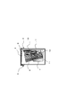
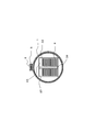
- the perspective view which shows the sensor storage container which concerns on Embodiment 1 of this invention.
- Sectional drawing of the sensor storage container of FIG. The perspective view showing the state which opens the sensor storage container of FIG. 1 with a finger
- Sectional drawing of the sensor storage container of FIG. Sectional drawing showing the state which takes out a sensor with a finger
- the disassembled perspective view which shows the structure of the sensor accommodated in the sensor storage container of FIG. (A) is a top view which shows the structure of the sensor of FIG.
- FIG. 7B is a side view showing the configuration of the sensor of FIG.
- the top view which shows the structure of the sensor storage container which concerns on Embodiment 2 of this invention.
- the top view which shows the structure of the sensor storage container which concerns on Embodiment 3 of this invention.
- the principal part enlarged view of the inner case of the sensor storage container which concerns on Embodiment 4 of this invention.
- the sensor storage container of the present embodiment is a container for storing a plurality of biological sample measurement sensors (sensors 8) for measuring blood sugar levels or the like, for example, as shown in FIG. 1, an opening / closing lid 2, a hinge portion 3, an inner case 7, and a connecting body (connecting portion) 9.
- the bottomed cylindrical container body 1 has an opening on the upper surface.
- the open / close lid 2 is provided in an openable / closable state at the opening of the container body 1.
- the hinge portion 3 connects a peripheral portion of the opening of the container body 1 and a part of the opening / closing lid 2. That is, the opening / closing lid 2 is connected to the container body 1 via the hinge part 3 at the periphery of the opening of the container body 1 as shown in FIG.
- the knob portion 4 provided on the side opposite to the hinge portion 3 is lifted upward, the opening / closing lid 2 rotated about the hinge portion 3 is opened, and the opening of the container body 1 is externally provided. Exposed to.
- FIG. 3 shows a state in which the opening / closing lid 2 is slightly opened with respect to the container body 1.
- the finger 5 of the left hand has the container body 1 and the finger 6 of the right hand has the opening / closing lid 2.
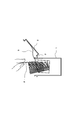
- the opening / closing lid 2 is fully opened with respect to the container body 1 as shown in FIG.
- the inner case 7 is a bottomed cylindrical case having an opening on the upper surface, and can be moved up and down in the container body 1 as the opening / closing lid 2 is opened and closed. 1 is housed.
- a plurality of sensors 8 are accommodated in the inner case 7.
- the connecting body 9 has flexibility, and connects a portion on the hinge portion 3 side in the opening of the inner case 7 and a portion separated from the end portion on the hinge portion 3 side in the opening / closing lid 2. More specifically, the first end of the coupling body 9 is coupled to the hinge portion 3 side portion of the opening of the inner case 7. The second end opposite to the first end is connected to a portion of the opening / closing lid 2 that is a predetermined distance away from the end on the hinge portion 3 side.
- the inner case 7 is connected to the open / close lid 2 via the flexible connecting body 9 on the hinge portion 3 side.
- the inner case 7 is held in the lower space in the container main body 1 in a state where the opening / closing lid 2 is put on the upper surface opening of the container main body 1.
- the upper end of the sensor 8 is stored in the container body 1.
- the second end of the connecting body 9 is moved along with the opening operation of the opening / closing lid 2. It moves to the outside of the upper surface of the container body 1 together with the opening / closing lid 2.
- the inner case 7 moves upward in the container body 1 so as to be pulled up by the connecting body 9.
- the upper end of the sensor 8 protrudes upward from the upper surface opening of the container body 1.
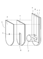
- the lower part is the connection part 10 side and the upper part is a connection part on the inner surface on the opposite side to the connection part 10 to the opening / closing lid 2 of the inner case 7.
- An inclined side surface 11 is provided on the side opposite to 10.
- the bottom surface of the inner case 7 is provided with an inclined bottom surface 12 with the connecting portion 10 side facing upward and the opposite side to the connecting portion 10 facing downward.
- the inclined bottom surface 12 is provided at the bottom portion of the inner case 7 so as to be inclined downward from the connecting portion 10 side toward the opposite side. Accordingly, the sensor 8 inserted into the inner case 7 is held in a state where the sensor 8 is tilted toward the knob portion 4 with respect to the vertical direction, as shown in FIGS. 2 and 4.
- the opening / closing lid 2 is opened and the inner case 7 is raised in the container body 1 as shown in FIG. In this state, it is possible to form a state in which the upper end of the sensor 8 is greatly expanded compared to the lower end side.
- the user can easily pick up the sensor 8 by picking up the upper end portion of one sensor 8.
- the sensor 8 stored in the sensor storage container is formed by overlapping a plate-like spacer 14 and a plate-like cover 15 on a substrate 13 as shown in FIGS. Yes.
- an electrode 16 serving as a working electrode, an electrode 17 serving as a counter electrode, and an electrode 18 serving as a detection electrode are disposed on the substrate 13 at a predetermined interval.
- the reagent 19 is placed on the electrodes 16 to 18 on the first end side of the sensor 8.
- a reagent supply path 20 extending from one end side of the sensor 8 to the reagent 19 is formed in the spacer 14.
- an air hole 21 is formed in a portion of the cover 15 facing the rear side of the reagent supply path 20. That is, when blood is spotted on the first end side of the reagent supply path 20, the blood advances to the reagent 19 due to the capillary phenomenon of the reagent supply path 20. Then, the blood sugar level is measured by the reaction between the blood and the reagent 19. In order to perform such measurement, the electrodes 16 to 18 are exposed on the second end side of the sensor 8 in order to make an electrical connection to the measuring device.
- the spacer 14 and the cover 15 are superimposed on the substrate 13 on the first end side of the substrate 13.
- the spacer 14 and the cover 15 are shorter than the substrate 13, so that the spacer 14 and the cover 15 are not superposed on the substrate 13. It becomes.
- the electrodes 16 to 18 are exposed to the outside without being covered with the cover 15 or the like.
- the second end side of the sensor 8 is thinner than the first end side because the spacer 14 and the cover 15 are not overlapped.
- a plurality of sensors 8 are accommodated in the inner case 7 such that the thin second end side faces downward in the inner case 7. Therefore, as shown in FIG. 2, the inner case 7 is accommodated in the container body 1 and the opening / closing lid 2 is closed, and then the opening / closing lid 2 is opened and the inner case 7 is raised as shown in FIG. When the upper end (first end side) of the sensor 8 protrudes above the upper surface opening of the container body 1, the lower end side (second end side) of the thin sensor 8 is adjacent as shown in FIG. The distance from the lower end of the sensor 8 is reduced.
- the gap between the upper end of the sensor 8 and the upper end of the adjacent sensor 8 is widened as the gap on the lower end side of the sensor is narrowed. That is, since the plurality of sensors 8 are in a state in which the peacock spreads its wings, as shown in FIG. 4, the upper ends of one sensor 8 protruding upward from the upper surface opening of the container body 1 are shown in FIG. As shown in FIG. In addition, the gap between the upper ends of the adjacent sensors 8 is increased in this manner because the inclined side surface 11 and the inclined bottom surface 12 described above are inclined in a desired direction.
- the lower end side of the sensor 8 inserted into the inner case 7 is made thinner than the upper end side that is picked up with a finger when taking out. Therefore, the electrodes 16 to 18 are exposed without overlapping the spacer 14 and the cover 15. However, since the electrodes 16 to 18 are inserted downward in the inner case 7, the portions of the electrodes 16 to 18 of the sensor 8 are disposed on the bottom surface side of the inner case 7. Therefore, as shown in FIG. 5, it is possible to avoid that the finger touches the electrodes 16 to 18 when picking up with the finger.
- Embodiment 2 The sensor storage container according to Embodiment 2 of the present invention will be described below with reference to FIG.
- the inner case 22 has two (a plurality of examples) storage portions 23 at positions symmetrical to the hinge portion 3 in a plan view of the sensor storage container. is doing.
- each of the storage portions 23 has a dimension slightly wider than the width of the sensor in a direction parallel to the hinge portion 3.
- the inner case 24 has two (a plurality of examples) storage portions 25 at symmetrical positions with respect to the hinge portion 3.
- the storage portions 25, 25 adjacent to each other in the inner case 24 include a partition wall portion 26 that separates them, a side surface portion 27 that faces the partition wall portion 26, and a side surface portion 28 that connects the side surface portions 27 to each other. have.
- the side surface portion 28 has an inclined surface in which the partition wall portion 26 side is located away from the hinge portion 3 and the both side surface portion 27 sides are disposed closer to the hinge portion 3 side than the partition wall portion 26 side.
- the sensors 8 respectively stored in the left and right storage portions 25 are stored in a state where they are inclined in different directions. That is, the sensors 8 housed in the left and right housing parts 25 are housed so that the surfaces thereof are aligned with the side face part 28 inclined as described above in plan view. Thereby, when picking out only one sensor 8 stored in a plurality of adjacent storage portions 25, 25, the direction of the sensor 8 stored in the adjacent storage 25 is different, so that it is easier to pick out. it can.
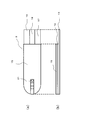
- Embodiment 4 The sensor storage container according to Embodiment 4 of the present invention will be described below with reference to FIG.
- the side connected to the flexible connecting body 9 in the inner case 22 shown in FIG. 8, that is, the wall surface 29 of the container body 1 is higher than the other wall surfaces constituting the inner case 22. Is low.
- the first end of the connecting body 9 is connected to the upper end of the outer peripheral surface 29.
- the sensor storage container of the present invention has an effect that the sensors can be smoothly taken out one by one, and thus can be widely applied to containers that store various sensors.
Landscapes
- Health & Medical Sciences (AREA)
- Engineering & Computer Science (AREA)
- Life Sciences & Earth Sciences (AREA)
- Biomedical Technology (AREA)
- Surgery (AREA)
- Mechanical Engineering (AREA)
- Molecular Biology (AREA)
- General Health & Medical Sciences (AREA)
- Physics & Mathematics (AREA)
- Medical Informatics (AREA)
- Chemical & Material Sciences (AREA)
- Animal Behavior & Ethology (AREA)
- Public Health (AREA)
- Veterinary Medicine (AREA)
- Heart & Thoracic Surgery (AREA)
- Nuclear Medicine, Radiotherapy & Molecular Imaging (AREA)
- Optics & Photonics (AREA)
- Urology & Nephrology (AREA)
- Hematology (AREA)
- Food Science & Technology (AREA)
- Medicinal Chemistry (AREA)
- Analytical Chemistry (AREA)
- Biochemistry (AREA)
- General Physics & Mathematics (AREA)
- Immunology (AREA)
- Pathology (AREA)
- Biophysics (AREA)
- Packaging Frangible Articles (AREA)
- Closures For Containers (AREA)
Abstract
Priority Applications (3)
| Application Number | Priority Date | Filing Date | Title |
|---|---|---|---|
| JP2014511102A JP5931184B2 (ja) | 2012-04-19 | 2013-04-15 | センサ収納容器 |
| US14/394,528 US20150076016A1 (en) | 2012-04-19 | 2013-04-15 | Sensor storage container |
| US15/937,421 US10321966B2 (en) | 2012-04-19 | 2018-03-27 | Sensor storage container |
Applications Claiming Priority (2)
| Application Number | Priority Date | Filing Date | Title |
|---|---|---|---|
| JP2012095334 | 2012-04-19 | ||
| JP2012-095334 | 2012-04-19 |
Related Child Applications (2)
| Application Number | Title | Priority Date | Filing Date |
|---|---|---|---|
| US14/394,528 A-371-Of-International US20150076016A1 (en) | 2012-04-19 | 2013-04-15 | Sensor storage container |
| US15/937,421 Division US10321966B2 (en) | 2012-04-19 | 2018-03-27 | Sensor storage container |
Publications (1)
| Publication Number | Publication Date |
|---|---|
| WO2013157242A1 true WO2013157242A1 (fr) | 2013-10-24 |
Family
ID=49383213
Family Applications (1)
| Application Number | Title | Priority Date | Filing Date |
|---|---|---|---|
| PCT/JP2013/002549 Ceased WO2013157242A1 (fr) | 2012-04-19 | 2013-04-15 | Récipient de stockage de capteurs |
Country Status (3)
| Country | Link |
|---|---|
| US (2) | US20150076016A1 (fr) |
| JP (1) | JP5931184B2 (fr) |
| WO (1) | WO2013157242A1 (fr) |
Cited By (1)
| Publication number | Priority date | Publication date | Assignee | Title |
|---|---|---|---|---|
| WO2025074465A1 (fr) * | 2023-10-02 | 2025-04-10 | 有限会社ティークラフト | Instrument de stockage de puces de capteur et outil de récupération de puces de capteur |
Families Citing this family (5)
| Publication number | Priority date | Publication date | Assignee | Title |
|---|---|---|---|---|
| WO2009140627A2 (fr) * | 2008-05-15 | 2009-11-19 | Csp Technologies, Inc. | Flacon muni d'un joint d'étanchéité non circulaire |
| US9297674B2 (en) * | 2012-06-11 | 2016-03-29 | Panasonic Healthcare Holdings Co., Ltd. | Sensor housing container and sensor attachment method using same |
| CN106073902A (zh) * | 2016-07-29 | 2016-11-09 | 万象设计江苏有限责任公司 | 一种拨动式体温表专用储存盒 |
| CN106137404A (zh) * | 2016-07-29 | 2016-11-23 | 万象设计江苏有限责任公司 | 一种体温表专用储存盒 |
| US11883773B2 (en) | 2022-02-21 | 2024-01-30 | Oscar Galan | Odor filtering lid assembly |
Citations (5)
| Publication number | Priority date | Publication date | Assignee | Title |
|---|---|---|---|---|
| US2039559A (en) * | 1933-03-17 | 1936-05-05 | Hyman R Segal | Cigarette case |
| US3091327A (en) * | 1961-05-11 | 1963-05-28 | Gerald J Lalley | Receptacle for storing film and the like |
| JPH03126884U (fr) * | 1990-04-02 | 1991-12-20 | ||
| WO2008122402A1 (fr) * | 2007-04-05 | 2008-10-16 | Friedrich Sanner Gmbh & Co. Kg | Contenant de stockage d'articles à emballer |
| JP2011137839A (ja) * | 2004-04-19 | 2011-07-14 | Panasonic Corp | 血液成分の測定方法、それに用いるバイオセンサおよび測定装置 |
Family Cites Families (8)
| Publication number | Priority date | Publication date | Assignee | Title |
|---|---|---|---|---|
| JP2722263B2 (ja) | 1989-10-11 | 1998-03-04 | ペルメレック電極株式会社 | 電解用電極及びその製造方法 |
| JP3786258B2 (ja) | 2001-11-09 | 2006-06-14 | 松下電器産業株式会社 | 容器 |
| US7172728B2 (en) * | 2002-04-02 | 2007-02-06 | Lifescan, Inc. | Test strip containers and methods of using the same |
| US7387204B2 (en) * | 2003-07-29 | 2008-06-17 | Bao Sheng Corporation | Pull-up tray container |
| US8778168B2 (en) * | 2007-09-28 | 2014-07-15 | Lifescan, Inc. | Systems and methods of discriminating control solution from a physiological sample |
| US8236254B2 (en) * | 2009-05-14 | 2012-08-07 | Abbott Diabetes Care Inc. | Cap-linked test strip carrier for vial augmentation |
| JP2011117912A (ja) * | 2009-12-07 | 2011-06-16 | Nipro Corp | バイオセンサ収納容器 |
| US8757386B2 (en) * | 2010-09-30 | 2014-06-24 | Abbott Diabetes Care Inc. | Analyte test strip containers and inserts |
-
2013
- 2013-04-15 US US14/394,528 patent/US20150076016A1/en not_active Abandoned
- 2013-04-15 JP JP2014511102A patent/JP5931184B2/ja active Active
- 2013-04-15 WO PCT/JP2013/002549 patent/WO2013157242A1/fr not_active Ceased
-
2018
- 2018-03-27 US US15/937,421 patent/US10321966B2/en active Active
Patent Citations (5)
| Publication number | Priority date | Publication date | Assignee | Title |
|---|---|---|---|---|
| US2039559A (en) * | 1933-03-17 | 1936-05-05 | Hyman R Segal | Cigarette case |
| US3091327A (en) * | 1961-05-11 | 1963-05-28 | Gerald J Lalley | Receptacle for storing film and the like |
| JPH03126884U (fr) * | 1990-04-02 | 1991-12-20 | ||
| JP2011137839A (ja) * | 2004-04-19 | 2011-07-14 | Panasonic Corp | 血液成分の測定方法、それに用いるバイオセンサおよび測定装置 |
| WO2008122402A1 (fr) * | 2007-04-05 | 2008-10-16 | Friedrich Sanner Gmbh & Co. Kg | Contenant de stockage d'articles à emballer |
Cited By (1)
| Publication number | Priority date | Publication date | Assignee | Title |
|---|---|---|---|---|
| WO2025074465A1 (fr) * | 2023-10-02 | 2025-04-10 | 有限会社ティークラフト | Instrument de stockage de puces de capteur et outil de récupération de puces de capteur |
Also Published As
| Publication number | Publication date |
|---|---|
| JP5931184B2 (ja) | 2016-06-08 |
| US20180214231A1 (en) | 2018-08-02 |
| JPWO2013157242A1 (ja) | 2015-12-21 |
| US20150076016A1 (en) | 2015-03-19 |
| US10321966B2 (en) | 2019-06-18 |
Similar Documents
| Publication | Publication Date | Title |
|---|---|---|
| JP5931184B2 (ja) | センサ収納容器 | |
| US8684172B2 (en) | Analyte sensor container systems with sensor elevator and storage methods | |
| US9297674B2 (en) | Sensor housing container and sensor attachment method using same | |
| JP5494272B2 (ja) | 板状物収納容器 | |
| US20160258926A1 (en) | Sensor storage container | |
| EP2188627A1 (fr) | Contenant pour bandes de test | |
| CN104838265A (zh) | 用于电化学传感器的分配器 | |
| CN106574921B (zh) | 用于堆叠式传感器分配系统的传感器夹和使用该传感器夹的系统 | |
| JP5517125B2 (ja) | 細胞測定装置 | |
| KR101684737B1 (ko) | 내용물 취출 기능을 가진 상자 | |
| JP2003146381A (ja) | 容 器 | |
| US9103772B2 (en) | Body for storing biosensors and measurement device using the biosensors | |
| JP5716154B2 (ja) | 生体試料測定センサと、それを収納した収納容器 | |
| JP2013136398A (ja) | 試験紙収納容器 | |
| JP2000314711A (ja) | センサーの包装体及びその使用方法 | |
| JP3167442U (ja) | つけまつげ収容器具 | |
| CN206345243U (zh) | 一种试纸存放筒 | |
| CN109890718B (zh) | 具有内部拇指状突片的容器以及相关组件 | |
| JP7540156B2 (ja) | 防湿容器 | |
| JPH044222Y2 (fr) | ||
| JP2008050037A (ja) | 板状内容物一枚取出容器 | |
| JP2006188255A (ja) | 板状検査紙振出し容器 | |
| CN109154595B (zh) | 用于物品,特别是用于测试条的分配器 | |
| JP6619147B2 (ja) | サーベイメータ | |
| JP2015114256A (ja) | 生体情報測定器収納ケース |
Legal Events
| Date | Code | Title | Description |
|---|---|---|---|
| 121 | Ep: the epo has been informed by wipo that ep was designated in this application |
Ref document number: 13778115 Country of ref document: EP Kind code of ref document: A1 |
|
| ENP | Entry into the national phase |
Ref document number: 2014511102 Country of ref document: JP Kind code of ref document: A |
|
| WWE | Wipo information: entry into national phase |
Ref document number: 14394528 Country of ref document: US |
|
| NENP | Non-entry into the national phase |
Ref country code: DE |
|
| 122 | Ep: pct application non-entry in european phase |
Ref document number: 13778115 Country of ref document: EP Kind code of ref document: A1 |