WO2013157251A1 - Dispositif de codage vidéo, procédé de codage vidéo, programme de codage vidéo, dispositif de transmission, procédé de transmission, programme de transmission, dispositif de décodage vidéo, procédé de décodage vidéo, programme de décodage vidéo, dispositif de réception, procédé de réception et programme de réception - Google Patents
Dispositif de codage vidéo, procédé de codage vidéo, programme de codage vidéo, dispositif de transmission, procédé de transmission, programme de transmission, dispositif de décodage vidéo, procédé de décodage vidéo, programme de décodage vidéo, dispositif de réception, procédé de réception et programme de réception Download PDFInfo
- Publication number
- WO2013157251A1 WO2013157251A1 PCT/JP2013/002565 JP2013002565W WO2013157251A1 WO 2013157251 A1 WO2013157251 A1 WO 2013157251A1 JP 2013002565 W JP2013002565 W JP 2013002565W WO 2013157251 A1 WO2013157251 A1 WO 2013157251A1
- Authority
- WO
- WIPO (PCT)
- Prior art keywords
- prediction
- motion information
- block
- motion
- information
- Prior art date
- Legal status (The legal status is an assumption and is not a legal conclusion. Google has not performed a legal analysis and makes no representation as to the accuracy of the status listed.)
- Ceased
Links
Images
















Classifications
-
- H—ELECTRICITY
- H04—ELECTRIC COMMUNICATION TECHNIQUE
- H04N—PICTORIAL COMMUNICATION, e.g. TELEVISION
- H04N19/00—Methods or arrangements for coding, decoding, compressing or decompressing digital video signals
- H04N19/50—Methods or arrangements for coding, decoding, compressing or decompressing digital video signals using predictive coding
- H04N19/503—Methods or arrangements for coding, decoding, compressing or decompressing digital video signals using predictive coding involving temporal prediction
- H04N19/51—Motion estimation or motion compensation
- H04N19/577—Motion compensation with bidirectional frame interpolation, i.e. using B-pictures
-
- H—ELECTRICITY
- H04—ELECTRIC COMMUNICATION TECHNIQUE
- H04N—PICTORIAL COMMUNICATION, e.g. TELEVISION
- H04N19/00—Methods or arrangements for coding, decoding, compressing or decompressing digital video signals
- H04N19/10—Methods or arrangements for coding, decoding, compressing or decompressing digital video signals using adaptive coding
- H04N19/102—Methods or arrangements for coding, decoding, compressing or decompressing digital video signals using adaptive coding characterised by the element, parameter or selection affected or controlled by the adaptive coding
- H04N19/103—Selection of coding mode or of prediction mode
- H04N19/105—Selection of the reference unit for prediction within a chosen coding or prediction mode, e.g. adaptive choice of position and number of pixels used for prediction
-
- H—ELECTRICITY
- H04—ELECTRIC COMMUNICATION TECHNIQUE
- H04N—PICTORIAL COMMUNICATION, e.g. TELEVISION
- H04N19/00—Methods or arrangements for coding, decoding, compressing or decompressing digital video signals
- H04N19/10—Methods or arrangements for coding, decoding, compressing or decompressing digital video signals using adaptive coding
- H04N19/102—Methods or arrangements for coding, decoding, compressing or decompressing digital video signals using adaptive coding characterised by the element, parameter or selection affected or controlled by the adaptive coding
- H04N19/103—Selection of coding mode or of prediction mode
- H04N19/109—Selection of coding mode or of prediction mode among a plurality of temporal predictive coding modes
-
- H—ELECTRICITY
- H04—ELECTRIC COMMUNICATION TECHNIQUE
- H04N—PICTORIAL COMMUNICATION, e.g. TELEVISION
- H04N19/00—Methods or arrangements for coding, decoding, compressing or decompressing digital video signals
- H04N19/10—Methods or arrangements for coding, decoding, compressing or decompressing digital video signals using adaptive coding
- H04N19/134—Methods or arrangements for coding, decoding, compressing or decompressing digital video signals using adaptive coding characterised by the element, parameter or criterion affecting or controlling the adaptive coding
- H04N19/157—Assigned coding mode, i.e. the coding mode being predefined or preselected to be further used for selection of another element or parameter
-
- H—ELECTRICITY
- H04—ELECTRIC COMMUNICATION TECHNIQUE
- H04N—PICTORIAL COMMUNICATION, e.g. TELEVISION
- H04N19/00—Methods or arrangements for coding, decoding, compressing or decompressing digital video signals
- H04N19/10—Methods or arrangements for coding, decoding, compressing or decompressing digital video signals using adaptive coding
- H04N19/169—Methods or arrangements for coding, decoding, compressing or decompressing digital video signals using adaptive coding characterised by the coding unit, i.e. the structural portion or semantic portion of the video signal being the object or the subject of the adaptive coding
- H04N19/17—Methods or arrangements for coding, decoding, compressing or decompressing digital video signals using adaptive coding characterised by the coding unit, i.e. the structural portion or semantic portion of the video signal being the object or the subject of the adaptive coding the unit being an image region, e.g. an object
- H04N19/176—Methods or arrangements for coding, decoding, compressing or decompressing digital video signals using adaptive coding characterised by the coding unit, i.e. the structural portion or semantic portion of the video signal being the object or the subject of the adaptive coding the unit being an image region, e.g. an object the region being a block, e.g. a macroblock
Definitions
- the present invention relates to a video signal encoding and decoding technique, and more particularly to a video encoding and decoding technique used for motion compensation prediction.
- moving picture coding represented by H.264 (hereinafter referred to as AVC) and the like
- AVC moving picture coding represented by H.264
- AVC moving picture coding
- a picture to be coded which is a picture signal to be coded is already coded and decoded.
- the detected local decoded signal is used as a reference picture, and a motion amount (hereinafter referred to as a motion vector) between the target picture and the reference picture is detected and predicted in a predetermined encoding processing unit (hereinafter referred to as an encoding target block).
- Motion compensated prediction that generates a signal is used.
- AVC single prediction for generating a prediction signal in a single direction using one motion vector from one reference picture in motion compensation prediction, and a prediction signal using two motion vectors from two reference pictures Bi-prediction is used to generate A method of changing the size (hereinafter referred to as prediction block size) of a block (hereinafter referred to as prediction target block) that is a prediction processing target within a 16 ⁇ 16 pixel two-dimensional block that is an encoding target block.
- prediction target block a block that is a prediction processing target within a 16 ⁇ 16 pixel two-dimensional block that is an encoding target block.
- it is applied to a method for selecting a reference picture used for prediction from a plurality of reference pictures, and the accuracy of a motion vector is expressed with 1/4 pixel accuracy, thereby improving the accuracy of a prediction signal and transmitting
- the information amount of the difference hereinafter, prediction error
- information specifying the prediction mode information and the reference image is selected and transmitted together with the motion vector information.
- the information specifying the transmitted prediction mode information and the reference image and the decoded motion vector information are transmitted. In accordance with the motion compensation prediction process.
- a motion vector of an encoded block adjacent to the processing target block is set as a prediction motion vector (hereinafter referred to as a prediction vector), and a difference between the motion vector of the processing target block and the prediction vector is obtained. Is transmitted as an encoded vector to improve the compression efficiency.
- AVC uses a motion vector used for coding a block of a reference picture at the same position as a prediction target block, It is possible to use direct motion compensated prediction that realizes motion compensated prediction without transmitting.
- Another solution is to reduce the number of motion vectors to be encoded by prohibiting bi-prediction and using only uni-prediction when the prediction block size is small in the encoding device as in Patent Document 1.
- a technique for preventing an increase in the code amount of a motion vector is known.
- the direct motion compensated prediction described above pays attention to the continuity of motion in the temporal direction in the block of the reference picture located at the same position as the prediction target block, and uses the motion information of other blocks as they are.
- the motion compensation prediction process is performed without encoding the difference vector as an encoded vector.
- an interpolation filter using a plurality of adjacent pixels is used to generate a 1/4 pixel accuracy specified by the motion vector.
- a reference picture of an area corresponding to the number of pixels corresponding to the number of taps of the interpolation filter horizontally and vertically with respect to the prediction block size It is necessary to acquire an image signal.
- the prediction block size is reduced, there is a problem that the memory access amount of the reference picture increases, and the same problem remains when direct motion compensation prediction is used.
- the memory access amount of the reference picture in the encoding device can be reduced together with the number of motion vectors, but in the decoding device, it is encoded. Since the restriction on the number of motion vectors to be recognized cannot be recognized, a decoding processing capability assuming a case where bi-prediction is performed is necessary to realize a real-time decoding process. In addition, when a prediction method that does not transmit an encoded vector, such as direct motion compensation prediction, is used under conditions where implicit bi-prediction is used, bi-prediction prediction signal generation is required, which is required by the decoding device. The maximum memory access amount cannot be reduced, and the problem is not solved.
- the present invention has been made in view of such circumstances, and an object of the present invention is to provide a technique for improving the coding efficiency while limiting the memory access amount of a reference picture to a predetermined amount or less when using motion compensated prediction. There is to do.
- a moving picture encoding apparatus specifies a prediction block from a block in which a picture is divided into a plurality of blocks step by step, and the specified prediction block unit includes: A moving image encoding device for generating an encoded stream, wherein motion information is derived from at least one of a block spatially close to a prediction block to be encoded and a block close in time, and the encoding A candidate list construction unit (1506) for registering predetermined motion information from the derived motion information as a motion information candidate of a target prediction block and constructing a motion information candidate list, and the encoding target An encoding unit (118) for encoding index information for designating motion information candidates in the motion information candidate list used for the prediction block; A motion information conversion unit (1507) that converts a motion information candidate, and based on the motion information candidate, performs motion compensation prediction by either uni-prediction or bi-prediction, and generates a prediction signal of the prediction block to
- the motion information conversion unit (1507) performs prediction conversion for converting the prediction type information indicating the bi-prediction among the motion information candidates into the prediction type information indicating the single prediction, and the motion compensation prediction unit (112) ) Is a case where the block size of the prediction block to be encoded is a predetermined first size, and when the prediction type information indicates the bi-prediction, based on the motion information converted by the prediction conversion The motion compensation prediction is performed.
- This apparatus is a moving picture encoding apparatus that encodes the moving picture using motion compensation prediction in units of blocks obtained by dividing each picture of the moving picture, and is to be encoded by motion compensation using the derived motion information.
- a motion compensation prediction unit (112) that generates a prediction signal of a prediction block, and a first control parameter (inter_4x4_enable) that specifies whether or not motion compensation prediction is permitted in the prediction block size of the specified first size
- a coding block control parameter generation unit that generates a second control parameter (inter_bipred_restriction_idc) that specifies the second size and prohibits bi-prediction motion compensation in a prediction block size that is equal to or smaller than the specified second size.
- (122) and an encoding unit (118) that encodes information used for motion compensation prediction, including the first and second control parameters.
- Still another aspect of the present invention is a video encoding method.
- This method is a moving picture coding method in which a prediction block is identified from a block in which a picture is divided into a plurality of blocks and a coded stream is generated in units of the identified prediction block.
- Motion information is derived from at least one of a spatially close block and a temporally close block to the target prediction block, and the derived motion information is used as a motion information candidate for the prediction block to be encoded.
- An encoding step for encoding the motion information, a motion information conversion step for converting the motion information candidate, and the motion information candidate Zui by, and a motion compensated prediction step of generating a prediction signal of the prediction block to be the encoding target performs motion compensation prediction by either single prediction or bi-prediction.
- the motion information conversion step performs prediction conversion for converting the prediction type information indicating the bi-prediction among the motion information candidates into prediction type information indicating the uni-prediction, and the motion compensation prediction step includes the encoding
- the motion compensation prediction is performed based on the motion information converted by the prediction conversion. .
- Still another aspect of the present invention is a transmission device.
- This apparatus identifies a prediction block from a block obtained by dividing a picture into a plurality of blocks in stages, and is encoded by the moving picture coding method for generating an encoded stream in the identified prediction block unit.
- a packet processing unit that packetizes the encoded stream to obtain encoded data, and a transmission unit that transmits the packetized encoded data.
- the video encoding method derives motion information from at least one of a block spatially adjacent to a prediction block to be encoded and a block adjacent to temporally, and the motion of the prediction block to be encoded
- a motion compensation prediction step of performing compensation prediction and generating a prediction signal of the prediction block to be encoded.
- the motion information conversion step performs prediction conversion for converting the prediction type information indicating the bi-prediction among the motion information candidates into prediction type information indicating the uni-prediction, and the motion compensation prediction step includes the encoding
- the motion compensation prediction is performed based on the motion information converted by the prediction conversion. .
- Still another aspect of the present invention is a transmission method.
- a prediction block is identified from a block in which a picture is divided into a plurality of blocks in stages, and the coded image is encoded by the moving image coding method for generating an encoded stream in the identified prediction block unit.
- the video encoding method derives motion information from at least one of a block spatially adjacent to a prediction block to be encoded and a block adjacent to temporally, and the motion of the prediction block to be encoded
- a motion compensation prediction step of performing compensation prediction and generating a prediction signal of the prediction block to be encoded.
- the motion information conversion step performs prediction conversion for converting the prediction type information indicating the bi-prediction among the motion information candidates into prediction type information indicating the uni-prediction, and the motion compensation prediction step includes the encoding
- the motion compensation prediction is performed based on the motion information converted by the prediction conversion. .
- a video decoding device specifies a prediction block from a block in which a picture is divided into a plurality of blocks in stages, and decodes an encoded stream in units of the specified prediction block
- a decoding unit (1108) that decodes index information specifying motion information of the prediction block to be decoded from the encoded stream, and a block spatially adjacent to the prediction block to be decoded
- Motion information is derived from at least one of temporally adjacent blocks, and predetermined motion information is registered from among the derived motion information as motion information candidates of the prediction block to be decoded.
- the motion information conversion unit (3605) performs prediction conversion for converting the prediction type information indicating the bi-prediction among the motion information candidates into the prediction type information indicating the single prediction, and the motion compensation prediction unit (1114).
- the motion compensation prediction is performed based on the motion information.
- the apparatus is a moving picture decoding apparatus that decodes a coded stream obtained by coding the moving picture using motion compensated prediction in units of blocks obtained by dividing each picture of the moving picture, and the motion compensated prediction is performed from the coded stream. And a first control parameter for specifying whether or not motion compensated prediction is permitted in the prediction block size of the designated first size from the information used for the motion compensated prediction that has been decoded.
- inter_4x4_enable and a second control parameter (inter_bipred_restriction_idc) that specifies the second size and prohibits bi-prediction motion compensation in a prediction block size equal to or smaller than the specified second size (1108)
- a motion compensated prediction unit (1114) that generates a prediction signal of a decoding target prediction block using information used for the motion compensated prediction Equipped with a.
- the motion compensation prediction unit (1114) performs motion compensation prediction based on the first and second control parameters.
- Still another aspect of the present invention is a moving picture decoding method.
- This method is a moving picture decoding method in which a prediction block is specified from a block in which a picture is divided into a plurality of blocks in stages, and an encoded stream is decoded in the specified prediction block unit.
- a decoding step of decoding index information specifying motion information of the prediction block to be decoded from the stream, and at least one of a block spatially adjacent to the prediction block to be decoded and a block adjacent in time A candidate list construction step of deriving motion information from the above, and as a motion information candidate of the prediction block to be decoded, registering predetermined motion information from the derived motion information and constructing a motion information candidate list; A motion information conversion step for converting the motion information candidates; and the index of the motion information candidates.
- the motion information conversion step performs prediction conversion for converting prediction type information indicating the bi-prediction among the motion information candidates into prediction type information indicating the single prediction, and the motion compensation prediction step includes the decoding target Based on the motion information converted by the prediction conversion, when the block size of the prediction block to be is a predetermined first size and the prediction type information of the specified motion information indicates the bi-prediction The motion compensation prediction is performed.
- Still another aspect of the present invention is a receiving device.
- This apparatus specifies a prediction block from a block in which a picture is divided into a plurality of blocks in stages, and receives and decodes an encoded stream in which a moving image is encoded in the specified prediction block unit.
- a receiving unit that receives encoded data in which the encoded stream is packetized; a recovery unit that processes the received encoded stream to recover the original encoded stream; A decoding unit that decodes index information specifying motion information of the prediction block to be decoded from the encoded stream, a block that is spatially close to the prediction block that is to be decoded, and a block that is temporally close to the prediction block
- Motion information is derived from at least one of the above, and the motion information candidate of the prediction block to be decoded is derived as the motion information candidate
- a candidate list construction unit for registering predetermined motion information from among the motion information and constructing a motion information candidate list, a motion information conversion unit for converting the motion information candidates, and the index information of the motion information candidates.
- a motion-compensated prediction unit that performs motion-compensated prediction based on specified motion information by either uni-prediction or bi-prediction and generates a prediction signal of a prediction block to be decoded.
- the motion information conversion unit converts prediction type information indicating that the motion compensation prediction is performed by the bi-prediction among the motion information candidates into prediction type information indicating that the motion compensation prediction is performed by the single prediction.
- the motion compensation prediction unit is a case where the block size of the prediction block to be decoded is a predetermined first size, and the prediction type information of the designated motion information is the bi-prediction Indicates that the motion compensation prediction is performed, the motion compensation prediction is performed based on the prediction type information converted by the prediction conversion.
- Still another aspect of the present invention is a receiving method.
- This method specifies a prediction block from a block in which a picture is divided into a plurality of blocks in stages, and receives and decodes an encoded stream in which a moving image is encoded in the specified prediction block unit.
- a receiving step for receiving encoded data in which the encoded stream is packetized; a restoring step for packetizing the received encoded stream to restore the original encoded stream;
- a decoding step for decoding the index information specifying the motion information of the prediction block to be decoded from the encoded stream, a block spatially adjacent to the prediction block to be decoded, and a block adjacent in time Motion information is derived from at least one of the prediction block motion information candidates of the prediction block to be decoded.
- prediction type information indicating that the motion compensation prediction is performed by the bi-prediction among the motion information candidates is converted into prediction type information indicating that the motion compensation prediction is performed by the single prediction.
- the motion compensation prediction step is performed when the block size of the prediction block to be decoded is a predetermined first size, and the prediction type information of the designated motion information is the bi-prediction. Indicates that the motion compensation prediction is performed, the motion compensation prediction is performed based on the prediction type information converted by the prediction conversion.
- the present invention it is possible to improve the encoding efficiency while limiting the memory access amount of the reference picture to a predetermined amount or less.
- FIG. 1 It is a figure which shows the structure of the moving image encoder which concerns on Embodiment 1 of this invention. It is a figure which shows an example of the division
- FIGS. 8A and 8B are diagrams for explaining two prediction modes for encoding motion information used in motion compensated prediction according to Embodiment 1 of the present invention. It is a figure which shows the rough value of the reference image memory amount required for motion compensation prediction at the time of using a horizontal and vertical 7 tap filter for motion compensation prediction. It is a figure for demonstrating the control parameter which controls the block size and prediction process of motion compensation prediction based on Embodiment 1 of this invention. It is a figure which shows the structure of the moving image decoding apparatus which concerns on Embodiment 1 of this invention.
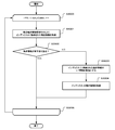
- 16 is a flowchart for explaining an operation of motion compensation prediction mode / prediction signal generation, which is steps S701, S702, S703, and S705 of FIG. 7, which operates via the motion compensation prediction block structure selection unit of FIG. 15. It is a flowchart for demonstrating the detailed operation
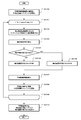
- FIGS. 23A and 23B are diagrams illustrating an example of comparison contents of combined motion information candidates. It is a figure which shows the time candidate block group used for a time joint movement information candidate list generation. It is a flowchart for demonstrating the detailed operation
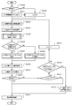
- FIG. 39 is a flowchart for explaining detailed operations of a predicted motion information decoding process in step S3805 of FIG. 38.
- FIG. It is an example which shows the restriction
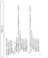
- Embodiment 1 of this invention it is an example which integrated two control parameters which control the block size of a motion compensation prediction, and a prediction process as one encoding transmission parameter. It is a figure for demonstrating the control parameter which controls the block size and prediction process of motion compensation prediction based on Embodiment 2 of this invention. It is a figure which shows the relationship between the control parameter which controls bi-prediction, and prediction block size based on Embodiment 2 of this invention. It is an example of the syntax regarding the parameter which controls the restriction
- FIG. 3 It is a figure which shows an example of the definition of a space periphery prediction block in combined motion information candidate generation in Embodiment 3 of this invention. It is a flowchart for demonstrating the detailed operation
- FIG. 1 is a diagram showing a configuration of a moving picture coding apparatus according to Embodiment 1 of the present invention. Hereinafter, the operation of each unit will be described.
- the moving picture coding apparatus according to Embodiment 1 includes an input terminal 100, an input picture memory 101, a coding block acquisition unit 102, a subtraction unit 103, an orthogonal transform / quantization unit 104, a prediction error coding unit 105, an inverse quantum.
- Inverse conversion unit 106 addition unit 107, intra-frame decoded image buffer 108, loop filter unit 109, decoded image memory 110, motion vector detection unit 111, motion compensation prediction unit 112, motion compensation prediction block structure selection unit 113, intra Prediction unit 114, intra prediction block structure selection unit 115, prediction mode selection unit 116, coding block structure selection unit 117, block structure / prediction mode information additional information coding unit 118, prediction mode information memory 119, multiplexing unit 120, An output terminal 121 and a coding block control parameter generation unit 122 are provided.
- the image signal input from the input terminal 100 is stored in the input image memory 101, and the image signal to be processed for the encoding target picture is input from the input image memory 101 to the encoding block acquisition unit 102.
- the image signal of the encoding target block extracted based on the position information of the encoding target block by the encoding block acquisition unit 102 is a subtraction unit 103, a motion vector detection unit 111, a motion compensation prediction unit 112, and an intra prediction unit 114. To be supplied.
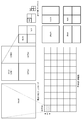
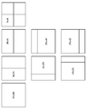
- FIG. 2 is a diagram illustrating an example of an encoding target image.
- the encoding target image is encoded in units of 64 ⁇ 64 pixel encoding blocks, and the prediction block is configured based on the encoding block. .
- the maximum prediction block size is 64 ⁇ 64 pixels, which is the same as the encoded block, and the minimum prediction block size is 4 ⁇ 4 pixels.
- the division configuration of a CU into prediction blocks includes non-division (2N ⁇ 2N), horizontal / vertical division (N ⁇ N), horizontal division only (2N ⁇ N), and vertical division only (N ⁇ 2N) is possible.
- the prediction block further divided horizontally and vertically can be hierarchically divided into prediction blocks as coding blocks (CU), and the hierarchy is expressed by the number of CU divisions.
- the divided areas viewed from the upper hierarchy CU of the four divided CUs are defined as division 1, division 2, division 3, and division 4.
- FIG. 3 is a diagram illustrating an example of a detailed definition of the predicted block size.
- the prediction block size in the case of performing motion compensation prediction that performs prediction using correlation between screens is divided only in the horizontal direction (2N ⁇ N), only in the vertical direction, with respect to the division configuration of the CU into prediction blocks. Can be defined and a total of 13 types of prediction block sizes can be defined. However, the prediction block size in the case of intra prediction in which prediction is performed using correlation in the screen is only in the horizontal direction. Since the division into two (2N ⁇ N) and the division only into the vertical direction (N ⁇ 2N) are not possible, a total of five types of prediction block sizes are defined.
- the partition configuration of the prediction block according to Embodiment 1 of the present invention is not limited to this combination.
- the encoding block size that can be defined can be changed by setting the maximum CU size and the minimum CU size using control parameters such as Maximum_cu_size and Minimum_cu_size shown in FIG. 3, and encoding and decoding these control parameters. Is possible.
- the subtraction unit 103 calculates a prediction error signal by subtracting the image signal supplied from the coding block acquisition unit 102 and the prediction signal supplied from the coding block structure selection unit 117, and outputs a prediction error signal. Is supplied to the orthogonal transform / quantization unit 104.
- the orthogonal transform / quantization unit 104 performs orthogonal transform and quantization on the prediction error signal supplied from the subtraction unit 103, and the quantized prediction error signal is subjected to a prediction error encoding unit 105 and an inverse quantization / inverse conversion unit. 106.
- the prediction error encoding unit 105 entropy-encodes the quantized prediction error signal supplied from the orthogonal transform / quantization unit 104, generates a code string for the prediction error signal, and supplies the code sequence to the multiplexing unit 120. .
- the inverse quantization / inverse transform unit 106 performs a process such as inverse quantization or inverse orthogonal transform on the quantized prediction error signal supplied from the orthogonal transform / quantization unit 104 to generate a decoded prediction error signal. Generated and supplied to the adder 107.
- the addition unit 107 adds the decoded prediction error signal supplied from the inverse quantization / inverse conversion unit 106 and the prediction signal supplied from the coding block structure selection unit 117 to generate a decoded image signal, and generates a decoded image signal.
- the signal is supplied to the intra-frame decoded image buffer 108 and the loop filter unit 109.
- the intra-frame decoded image buffer 108 supplies the decoded image in the same frame in the region adjacent to the encoding target block to the intra prediction unit 114 and also stores the decoded image signal supplied from the addition unit 107.
- the loop filter unit 109 performs a filtering process on the decoded image signal supplied from the adding unit 107 by applying a filter to remove distortion caused by encoding and to restore the image to a pre-encoded image.
- the resulting decoded image is supplied to the decoded image memory 110.
- the decoded image memory 110 stores the decoded image signal subjected to the filtering process supplied from the loop filter unit 109.
- a decoded image for which decoding of the entire image has been completed is stored as a reference image by a predetermined number of images, and the reference image signal is supplied to the motion vector detection unit 111 and the motion compensation prediction unit 112.
- the motion vector detection unit 111 receives the input of the image signal of the encoding target block supplied from the encoding block acquisition unit 102 and the reference image signal stored in the decoded image memory 110, and obtains a motion vector for each reference image.
- the motion vector value is detected and supplied to the motion compensation prediction unit 112 and the motion compensation prediction block structure selection unit 113.
- a general motion vector detection method calculates an error evaluation value for an image signal corresponding to a reference image moved by a predetermined movement amount from the same position as the image signal, and moves the movement amount that minimizes the error evaluation value. Let it be a vector.
- the error evaluation value a sum of absolute differences SAD (Sum of Absolute Difference) for each pixel, a sum of squared error values SSE (Sum of Square Error) for each pixel, or the like is used.
- the code amount related to the coding of the motion vector can also be included in the error evaluation value.
- the motion compensated prediction unit 112 is configured to decode the decoded image memory according to the information specifying the prediction block structure specified by the motion compensated prediction block structure selecting unit 113, the reference image specifying information, and the motion vector value input from the motion vector detecting unit 111.
- a prediction signal is generated by acquiring an image signal at a position obtained by moving the reference image indicated by the reference image designation information in 110 from the same position as the image signal of the prediction block by a motion vector value.
- the prediction mode specified by the motion compensated prediction block structure selection unit 113 is prediction from a single reference image
- a prediction signal acquired from one reference image is used as a motion compensation prediction signal
- two prediction modes are referenced.
- a weighted average of prediction signals acquired from two reference images is used as a motion compensation prediction signal
- the motion compensation prediction signal is supplied to the prediction mode selection unit 116.
- the ratio of the weighted average of bi-prediction is set to 1: 1.
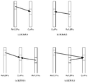
- 4 (a) to 4 (d) are diagrams for explaining the prediction type of motion compensation prediction.
- a process for performing prediction from a single reference image is defined as single prediction, and in the case of single prediction, prediction using either one of two reference images registered in the reference image management list, that is, L0 prediction or L1 prediction. I do.
- FIG. 4A shows a case in which the prediction image is uni-prediction and the reference image (RefL0Pic) for L0 prediction is at a time before the encoding target image (CurPic).
- FIG. 4B shows a case in which the prediction image is a single prediction and the reference image of the L0 prediction is at a time after the encoding target image.
- the L0 prediction reference image shown in FIGS. 4A and 4B can be replaced with the L1 prediction reference image (RefL1Pic) to perform single prediction.
- FIG. 4C illustrates a case where bi-prediction is performed, and the reference image for L0 prediction is at a time before the encoding target image and the reference image for L1 prediction is at a time after the encoding target image.
- FIG. 4D shows a case of bi-prediction, where the reference image for L0 prediction and the reference image for L1 prediction are at a time before the encoding target image.
- the relationship between the prediction type of L0 / L1 and time can be used without being limited to L0 being the past direction and L1 being the future direction.
- each of L0 prediction and L1 prediction may be performed using the same reference picture.
- whether to perform motion compensation prediction by single prediction or bi-prediction is determined based on, for example, information (for example, a flag) indicating whether to use L0 prediction and whether to use L1 prediction.
- Bi-prediction requires image information access to two reference image memories, and therefore may require twice or more memory bandwidth compared to single prediction.
- bi-prediction when the prediction block size of motion compensation prediction is small becomes a bottleneck of the memory band, and the bottleneck of the memory band is suppressed in the embodiment of the present invention.
- the motion compensated prediction block structure selection unit 113 detects the motion vector value detected for each reference image input from the motion vector detection unit 111 and the motion information stored in the prediction mode information memory 119 ( Based on the prediction type, motion vector value, and reference image designation information), the control parameters related to the prediction block size and motion compensation prediction mode defined in Embodiment 1 generated by the coding block control parameter generation unit 122 are The reference image designation information and the motion vector value used for each of the prediction block size and the motion compensation prediction mode that are input and determined based on the control parameter are set in the motion compensation prediction unit 112. Depending on the set value, the motion compensation prediction signal supplied from the motion compensation prediction unit 112 and the image signal of the target block to be encoded supplied from the coding block acquisition unit 102 are used to optimize the prediction block size and motion compensation prediction. Determine the mode.
- the motion compensated prediction block structure selection unit 113 uses the determined prediction block size, motion compensation prediction mode, prediction type corresponding to the prediction mode, motion vector, and information specifying the reference image designation information as a motion compensation prediction signal and a prediction error. Is supplied to the prediction mode selection unit 116 together with an error evaluation value for.
- the intra prediction unit 114 is adjacent to the encoding target block supplied from the intra-frame decoded image buffer 108 according to the intra prediction mode defined as the information specifying the prediction block structure specified by the intra prediction block structure selection unit 115.
- An intra prediction signal is generated using the decoded image in the same frame, and is supplied to the intra prediction block structure selection unit 115.
- Embodiment 1 Intra prediction block structure selection section 115 is generated by coding block control parameter generation section 122 according to intra prediction mode information stored in prediction mode information memory 119 and a plurality of defined intra prediction modes.
- the control parameter related to the prediction block size defined in the step is input, and the intra prediction mode used for each of the prediction block sizes determined based on the control parameter is set in the intra prediction unit 114.
- the optimal prediction block size and intra prediction mode are determined using the intra prediction signal supplied from the intra prediction unit 114 and the image signal of the encoding target block supplied from the coding block acquisition unit 102. To do.
- the intra prediction block structure selection unit 115 supplies information specifying the determined prediction block size and intra prediction mode to the prediction mode selection unit 116 together with the intra prediction signal and the error evaluation value for the prediction error.
- the prediction mode selection unit 116 is supplied from the motion compensated prediction block structure selection unit 113 and specifies the determined prediction block size, motion compensation prediction mode, prediction type according to the prediction mode, motion vector, and reference image designation information.
- CU size units that are hierarchically configured from the error evaluation value for the prediction error, and the error prediction value for the predicted prediction block size, intra prediction mode, and prediction error supplied from the intra prediction block structure selection unit 115 The optimum prediction mode is selected by comparing the error evaluation values.
- motion compensation prediction is selected as the optimal prediction mode information in units of CU size selected by the prediction mode selection unit 116 together with the sum of the prediction block size, the prediction signal, and the error evaluation value in units of CU size
- the intra prediction is selected as the motion compensation prediction mode
- the prediction type corresponding to the prediction mode, the motion vector, the information specifying the reference image designation information, and the motion compensation prediction signal, the intra prediction mode and the intra prediction signal are selected. Is supplied to the coding block structure selection unit 117.
- the coding block structure selection unit 117 is defined in Embodiment 1 generated by the coding block control parameter generation unit 122 based on the optimal prediction mode information in CU size units supplied from the prediction mode selection unit 116.
- the control parameter related to the encoded block size is input, the optimum CU_Depth configuration is selected in the encoded block size configuration determined based on the control parameter, the information for specifying the CU partition configuration, and the specified partition configuration.
- the optimal prediction mode information in the CU size and additional information related to the prediction mode are supplied to the block structure / prediction mode information additional information encoding unit 118 and the selected prediction signal is subtracted. 103 and the adder 107.
- the block structure / prediction mode information additional information encoding unit 118 is supplied from the encoding block structure selection unit 117, and specifies the CU partition configuration, and the optimal prediction mode information for the specified CU size for each partition configuration.
- the coding block unit The CU partition configuration and mode information used for prediction are encoded and supplied to the multiplexing unit 120, and the information is stored in the prediction mode information memory 119.
- the prediction mode information memory 119 predetermines the CU partition configuration of the coding block unit supplied from the block structure / prediction mode information additional information encoding unit 118 and the mode information used for prediction based on the minimum prediction block size unit. Memorize images. Since the first embodiment focuses on motion compensation prediction that is prediction between screens, motion information (prediction type, motion vector, and reference image index) that is information related to motion compensation prediction in mode information is used. And add a description.
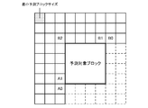
- the motion information of the adjacent block of the prediction block that is the processing target of motion compensation prediction is set as a spatial candidate block group, and the motion information of the block on ColPic and the surrounding blocks that are at the same position as the processing target prediction block is the time candidate block group. To do.
- ColPic is a decoded image different from the prediction block to be processed, and is stored in the decoded image memory 110 as a reference image.
- ColPic is a reference image decoded immediately before.
- ColPic is the reference image decoded immediately before, but the reference image immediately before in display order or the reference image immediately after in display order may be used, and the reference image used for ColPic is included in the encoded stream. Direct specification is also possible.
- the prediction mode information memory 119 supplies the motion information of the spatial candidate block group and the temporal candidate block group to the motion compensated prediction block structure selection unit 113 as motion information of the candidate block group, and intra prediction of adjacent blocks of the intra prediction block.
- the mode information is supplied to the intra prediction block structure selection unit 115.
- the multiplexing unit 120 includes a prediction error encoding sequence supplied from the prediction error encoding unit 105, a CU partitioning configuration in units of encoded blocks supplied from the block structure / prediction mode information additional information encoding unit 118, and prediction.
- the encoded bit stream is generated by multiplexing the encoded sequence of the mode information and the additional information used in the above, and the encoded bit stream is output to the recording medium / transmission path via the output terminal 121.
- the coding block control parameter generation unit 122 performs control parameters such as Maximum_cu_size and Minimum_cu_size shown in FIG. 3, which are parameters defining the coding block structure, and the block size and prediction processing of motion compensation prediction in the first embodiment. Generate parameters for defining a coding block structure or a prediction block structure, such as a control parameter to be limited, and a motion compensation prediction block structure selection unit 113, an intra prediction block structure selection unit 115, a coding block structure selection unit 117, And supplied to the block structure / prediction mode information additional information encoding unit 118. Details regarding the block size of motion compensation prediction and control parameters for limiting the prediction process will be described later.
- the configuration of the moving picture encoding apparatus shown in FIG. 1 can also be realized by hardware such as an information processing apparatus including a CPU (Central Processing Unit), a frame memory, and a hard disk.
- an information processing apparatus including a CPU (Central Processing Unit), a frame memory, and a hard disk.
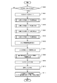
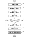
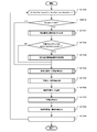
- FIG. 5 is a flowchart showing the flow of the encoding process in the video encoding apparatus according to Embodiment 1 of the present invention.
- CU_Depth which is a control parameter for CU partitioning
- a coding process target block image is obtained from the coding block acquisition unit 102 (S501).
- the motion vector detection unit 111 uses a motion vector value for each reference image according to CU partitioning from a block image to be predicted according to CU partitioning from the encoding target block image and a plurality of reference images stored in the decoded image memory 110. Is calculated (S502).
- the motion compensation prediction block structure selection unit 113 uses the motion vector supplied from the motion vector detection unit 111, the motion information and the intra prediction mode information stored in the prediction mode information memory 119, and performs the first embodiment.
- the prediction signal for each of the prediction block size and the motion compensation prediction mode defined in (1) is acquired using the motion compensation prediction unit 112, and the result of selecting the optimal prediction block size and prediction mode in CU units is output.
- the intra prediction block structure selection unit 115 acquires prediction signals for each of the prediction block size and the intra prediction mode using the intra prediction unit 114, and selects the optimal prediction block size and prediction mode in CU units. Is output.
- the coding block structure selection unit 117 generates a prediction mode and a prediction signal in the optimum coding block structure using these results (S503). Details of the processing in step S503 will be described later.
- the subtraction unit 103 calculates a difference between the encoded block image supplied from the encoded block acquisition unit 102 and the prediction signal supplied from the encoded block structure selection unit 117 as a prediction error signal (S504). ).
- the block structure / prediction mode information additional information encoding unit 118 includes a coding type, a prediction mode, a prediction type according to a prediction mode in the case of motion compensation prediction, a motion vector, and a coding structure supplied from the coding block structure selection unit 117.
- Information for specifying the reference image designation information and intra prediction mode information in the case of intra prediction are encoded according to a predetermined syntax structure, and encoded data of additional information related to the encoding structure and the prediction mode information is generated (S505). ).
- the prediction error encoding unit 105 entropy encodes the quantized prediction error signal generated by the orthogonal transform / quantization unit 104 to generate encoded data of the prediction error (S506).
- the multiplexing unit 120 is supplied from the coding structure supplied from the block structure / prediction mode information additional information encoding unit 118, encoded data of additional information related to the prediction mode information, and the prediction error encoding unit 105.
- the encoded data of the prediction error is multiplexed to generate an encoded bit stream (S507).
- the addition unit 107 adds the decoded prediction error signal supplied from the inverse quantization / inverse conversion unit 106 and the prediction signal supplied from the coding block structure selection unit 117 to generate a decoded image signal (S508).
- the prediction mode information memory 119 includes motion information (prediction when motion compensation prediction is used as additional information related to the coding structure and prediction mode information supplied from the block structure / prediction mode information additional information encoding unit 118. Type, motion vector, and reference image designation information) and intra prediction mode information when intra prediction is used are stored in units of the smallest prediction block size (S509).
- the decoded image signal generated by the addition unit 107 is stored in the intra-frame decoded image buffer 108, and the loop filter unit 109 performs a loop filter process for distortion removal (S510) and performs the filter.
- the decoded image signal is supplied to and stored in the decoded image memory 110 and used for motion compensation prediction processing of an encoded image to be encoded thereafter (S511).
- Max_CU_Depth a value indicating the number of hierarchies between the set maximum CU size and minimum CU size is set as Max_CU_Depth, and it is determined whether or not the CU_Depth of the target CU is smaller than Max_CU_Depth (S600).
- S600 Max_CU_Depth
- intra prediction block structure selection unit 115 and intra prediction unit 114 in FIG. 1 calculate intra prediction modes and generate prediction signals (S607). Intra prediction mode information, a prediction signal, and an error evaluation value in the target CU are calculated.
- the motion compensation prediction block structure selection unit 113 and the motion compensation prediction unit 112 select a motion compensation prediction block size, and generate a motion compensation prediction mode and a prediction signal for each selected prediction block (S608).
- a prediction block size, mode information, motion information, a prediction signal, and an error evaluation value for motion compensation prediction in the target CU are calculated. Details of step S608 will be described later.
- the coding block structure selecting unit 117 compares the error evaluation value of the intra prediction in the target CU with the error evaluation value of the motion compensated prediction, selects a prediction method with a small error, and selects intra / inter (motion compensated prediction). ) Is determined (S609).
- the lowest CU (Depth Max_CU_Depth) CU is sequentially compared with the upper CU, and the optimal CU_Depth for each divided region of the CU Prediction mode can be selected.
- an encoded block image to be predicted is acquired for the target CU (S700).
- motion compensation prediction mode / prediction signal generation processing is performed for each intra-CU division mode (S701 to S705).
- the motion compensation prediction mode / prediction signal generation processing when the intra-CU division mode is 2N ⁇ 2N is performed by setting NumPart which is a value indicating the number of divisions to 1 (S701). Subsequently, NumPart is set to 2, and motion compensation prediction mode / prediction signal generation processing is performed in the case of 2N ⁇ N (S702) and N ⁇ 2N (S703).
- step S704 when CU_Depth is equal to Max_CU_Depth, the target CU size is 8 ⁇ 8, and an inter_4x4_enable flag (to be described later) is 1 (S704: YES), NumPart is set to 4 and motion compensation is performed when N ⁇ N Prediction mode / prediction signal generation processing is performed (S705). Details of the motion compensation prediction mode / prediction signal generation processing performed in steps S701, S702, S703, and S705 will be described later. If the condition of step S704 is not satisfied (S704: NO), step S705 is skipped and the subsequent step is performed.
- Embodiment 1 motion compensated prediction / prediction signal generation in intra-CU division in the order of 2N ⁇ 2N (S701), 2N ⁇ N (S702), N ⁇ 2N (S703), and N ⁇ N (S705)
- the processing order of the steps of each of the CU divisions may be changed, and when processing is performed by a CPU or the like that can perform parallel processing, S701, S702, S703, and S705 are performed. Can also be performed in parallel.
- an error evaluation value for each intra-CU partition mode for which motion compensation prediction mode / prediction signal generation has been performed is compared, and an optimal prediction block size (PU) that is an optimal intra-CU partition mode is selected (S706).
- Prediction mode information / error evaluation value / prediction signal for the selected PU is stored (S707), and the process of step S608 in the flowchart of FIG. 6 ends.
- FIGS. 8A and 8B are diagrams for explaining two prediction modes for encoding motion information used in motion compensated prediction according to Embodiment 1 of the present invention.
- the prediction target block directly encodes its own motion information using the continuity of motion in the temporal direction and the spatial direction in the prediction target block and the encoded block adjacent to the prediction target block.
- the motion information of spatially and temporally adjacent blocks is used for encoding, which is called a joint prediction mode (merge mode).
- the spatially adjacent block refers to a block adjacent to the prediction target block among encoded blocks belonging to the same image as the prediction target block.
- the temporally adjacent blocks indicate blocks in the same spatial position as the prediction target block and in the vicinity thereof among blocks belonging to an encoded image different from the prediction target block.
- motion information that can be selectively combined from a plurality of adjacent block candidates can be defined, and the motion information is specified by encoding information (joined motion information index) that specifies the adjacent block to be used.
- the motion information acquired based on the information is used as it is for motion compensation prediction.
- a Skip mode is defined in which the prediction signal predicted in the joint prediction mode is a decoded picture without encoding prediction transmission of the prediction difference information, and a decoded image is obtained with information having only the combined motion information. Can be reproduced.
- the Skip mode can be used when the intra-CU division mode is 2N ⁇ 2N, and the motion information transmitted in the Skip mode is the designation information that defines the adjacent block as in the combined prediction mode.
- the second prediction mode is a technique for coding all the components of motion information individually and transmitting motion information with little prediction error to the prediction block, and is called a motion detection prediction mode.
- the motion detection prediction mode includes a prediction type indicating whether the prediction is bi-prediction or uni-prediction, information for identifying a reference image (reference image index), and encoding of motion information in the conventional motion compensation prediction.
- the information for specifying the motion vector is encoded separately.
- the prediction mode indicates whether to use single prediction or bi-prediction.
- single prediction single prediction information for specifying a reference image for one reference image, and a motion vector prediction vector
- the difference vector is encoded.
- bi-prediction information for specifying reference images for two reference images and a motion vector are individually encoded.
- the prediction vector for the motion vector is generated from the motion information of the adjacent block similarly to the AVC.
- the motion vector used for the prediction vector can be selected from a plurality of adjacent block candidates, and the motion vector is the prediction vector. Is transmitted by encoding two pieces of information (predicted vector index) for designating adjacent blocks to be used for and a difference vector.
- an integer motion existing in the reference image is generated.
- a pixel of the reference image at the motion position with a 1/4 pixel accuracy is calculated by an interpolation filter.
- a 7-tap FIR filter is used as an interpolation filter.
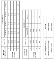
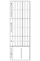
- FIG. 9 shows a case where a 7-tap filter is applied and a memory band is secured when performing uni-prediction and bi-prediction in each of the predictable block sizes definable for motion compensated prediction shown in FIG. 3 in the first embodiment.
- various configurations such as a configuration in which memory access is possible in units of horizontal 4 pixels and a configuration in which units of horizontal and vertical 2 ⁇ 2 pixels are possible can be taken.
- the memory access amount indicates the maximum value of the memory access amount that needs to be obtained at the minimum regardless of the configuration of the reference image memory.
- the 4 ⁇ 4 pixel size is the most encoded block size (LCU) unit.
- the memory access amount becomes larger, and access of nearly 6 times the size of 64 ⁇ 64 pixels is required.
- two prediction signals are acquired from reference images at different positions, so that twice as many memory accesses as in single prediction are required.
- a motion compensation prediction limiting method and a control parameter definition and setting method for limiting in which the memory access maximum amount of the reference image can be controlled step by step to limit the memory bandwidth, It is possible to achieve both the feasibility and encoding efficiency of a moving image encoding apparatus for fine images.
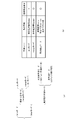
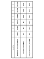
- FIG. 10 shows an example of the motion compensation prediction block size and control parameters for limiting the prediction processing, which are generated by the coding block control parameter generation unit 122 of FIG. 1 according to Embodiment 1 of the present invention. To do.
- inter_4x4_enable is a parameter for controlling the validity / invalidity of motion compensated prediction of 4 ⁇ 4 pixels, which is the smallest motion compensated prediction block size, and only prediction processing for which bi-prediction is performed among motion compensated predictions It consists of two parameters, inter_bipred_restriction_idc, which defines the block size that prohibits
- 4 ⁇ 4 bi-prediction, 4 ⁇ 8/8 ⁇ 4 bi-prediction, 4 ⁇ 4 mono-prediction, 8 ⁇ 8 bi-prediction, 8 ⁇ 16/16 ⁇ 8 bi-prediction, 4 ⁇ 8/8 ⁇ 4 single prediction, and 16 ⁇ 16 bi-prediction are in this order. Relatively accessed except for the minimum prediction block size of 4 ⁇ 4 pixels. The amount is small.
- inter_4x4_enable which is a control parameter for prohibiting the motion compensation prediction process itself, is prepared, and inter_bipred_restriction_idc that further restricts bi-prediction is prepared as a control parameter for each block size. Can control memory access amount explicitly.
- the amount of memory access is larger than that of 16 ⁇ 16 bi-prediction.
- the intra-CU partitioning mode is Since the entire motion compensated prediction with a prediction block size smaller than an N ⁇ N 8 ⁇ 8 block can be prohibited, the motion compensated prediction process itself is prohibited in a configuration having a restriction on a fixed minimum prediction block size. It is possible to control the memory access amount.
- the memory access amount is controlled by combining the minimum CU size value in addition to inter_4x4_enable and inter_bipred_restriction_idc.
- inter_bipred_restriction_idc defines a value from 0 to 5 as shown in FIG. 10, and from a state where there is no restriction on bi-prediction to a state where bi-prediction with a size of 16 ⁇ 16 blocks or less is restricted.
- the range of definition is an example, and it is also possible to define a control value that is smaller or more than this value as another configuration of the embodiment of the present invention.
- Control that disables the entire motion compensated prediction of a given size and a control parameter that restricts bi-prediction of motion compensated prediction of less than a given size, and controls the maximum memory access amount to be within the prescribed range
- FIG. 11 is a diagram showing a configuration of the moving picture decoding apparatus according to Embodiment 1 of the present invention. Hereinafter, the operation of each unit will be described.
- the video decoding apparatus according to Embodiment 1 includes an input terminal 1100, a demultiplexing unit 1101, a prediction difference information decoding unit 1102, an inverse quantization / inverse transform unit 1103, an addition unit 1104, an intra-frame decoded image buffer 1105, a loop filter.
- Unit 1106 decoded image memory 1107, prediction mode / block structure decoding unit 1108, prediction mode / block structure selection unit 1109, intra prediction information decoding unit 1110, motion information decoding unit 1111, prediction mode information memory 1112, intra prediction unit 1113, A motion compensation prediction unit 1114 and an output terminal 1115 are provided.
- the encoded bit stream is supplied from the input terminal 1100 to the demultiplexing unit 1101.
- the demultiplexing unit 1101 is used for the code string of the supplied coded bitstream, the coded string of prediction error information, the control parameters related to the coding block and the prediction block structure, the CU partition configuration and coding block unit, and the prediction.
- Mode information prediction mode according to the prediction mode in the case of motion compensated prediction, motion vector that is information specifying the motion vector, and reference image designation information, and intra prediction mode information in the case of intra prediction. Separate into coded sequences to be constructed.
- the coding sequence of the prediction error information is supplied to the prediction difference information decoding unit 1102, and the control parameter, the CU partition configuration of the coding block unit, and the coding sequence of the mode information used for prediction are predicted mode / block structure It supplies to the decoding part 1108.
- the prediction difference information decoding unit 1102 decodes the encoded sequence of the prediction error information supplied from the demultiplexing unit 1101, and generates a quantized prediction error signal.
- the prediction difference information decoding unit 1102 supplies the generated quantized prediction error signal to the inverse quantization / inverse transform unit 1103.
- the inverse quantization / inverse transform unit 1103 performs a process such as inverse quantization or inverse orthogonal transform on the quantized prediction error signal supplied from the prediction difference information decoding unit 1102 to generate a prediction error signal,
- the decoded prediction error signal is supplied to the adding unit 1104.
- the adder 1104 adds the decoded prediction error signal supplied from the inverse quantization / inverse transform unit 1103 and the prediction signal supplied from the prediction mode / block structure selection unit 1109 to generate a decoded image signal, and generates a decoded image signal.
- the signal is supplied to the intra-frame decoded image buffer 1105 and the loop filter unit 1106.
- the intra-frame decoded image buffer 1105 has the same function as the intra-frame decoded image buffer 108 in the moving picture encoding apparatus in FIG. 1, and supplies a decoded image signal in the same frame to the intra prediction unit 1113 as a reference image for intra prediction. At the same time, the decoded image signal supplied from the adding unit 1104 is stored.
- the loop filter unit 1106 has the same function as the loop filter unit 109 in the moving picture coding apparatus in FIG. 1, performs a distortion removal filter on the decoded image signal supplied from the addition unit 1104, and performs filter processing.
- the decoded image obtained as a result of the execution is supplied to the decoded image memory 1107.
- the decoded image memory 1107 has the same function as the decoded image memory 110 in the moving image encoding apparatus in FIG. 1, stores the decoded image signal supplied from the loop filter unit 1106, and uses the reference image signal as the motion compensation prediction unit 1114. To supply.
- the decoded image memory 1107 supplies the stored decoded image signal to the output terminal 1115 in accordance with the display order of images in accordance with the reproduction time.
- the prediction mode / block structure decoding unit 1108 is a control parameter that defines the CU structure shown in FIG. 3 based on the control parameters related to the coding block and the prediction block structure supplied from the demultiplexing unit 1101, and the control parameter shown in FIG. Such a motion compensation prediction block configuration and control parameters for limiting the prediction process are generated.
- the prediction mode / block structure decoding unit 1108 uses the CU division configuration for each coding block unit supplied from the demultiplexing unit 1101 and the coding sequence of the mode information used for prediction to determine the CU for each coding block unit.
- the mode information used for the division configuration and prediction is decoded to generate a prediction block size and a prediction mode, and the prediction type, motion vector, and reference image designation information corresponding to the prediction mode in the case of motion compensated prediction are specified.
- the motion information, which is information, and the intra prediction mode information in the case of intra prediction are separated, and the CU partition configuration and the prediction mode information for each coding block are supplied to the prediction mode / block structure selection unit 1109.
- the prediction mode / block structure decoding unit 1108 supplies intra prediction mode information to the intra prediction information decoding unit 1110 together with the prediction block size, and motion compensated prediction is used. If so, the motion information decoding unit 1111 is supplied with information for specifying the motion compensation prediction mode, the prediction type corresponding to the prediction mode, the motion vector, and the reference image designation information together with the prediction block size.
- the intra prediction information decoding unit 1110 decodes the prediction block size and intra prediction mode information supplied from the prediction mode / block structure decoding unit 1108, and reproduces the prediction block structure for the encoding target block and the intra prediction mode in each prediction block. To do.
- the intra prediction information decoding unit 1110 supplies the reproduced intra prediction mode to the intra prediction unit 1113 and also supplies it to the prediction mode information memory 1112.
- the motion information decoding unit 1111 is supplied from the prediction mode / block structure decoding unit 1108 and specifies the prediction block size, the motion compensation prediction mode, and the prediction type, motion vector, and reference image designation information corresponding to the prediction mode. From the decoded motion information and the motion information of the candidate block group supplied from the prediction mode information memory 1112 to reproduce the prediction type, motion vector, and reference image designation information used for motion compensation prediction, This is supplied to the compensation prediction unit 1114. The motion information decoding unit 1111 also supplies the reproduced motion information to the prediction mode information memory 1112. A detailed configuration of the motion information decoding unit 1111 will be described later.
- the prediction mode information memory 1112 has the same function as the prediction mode information memory 119 in the moving picture encoding apparatus in FIG. 1 and is supplied from the reproduced motion information supplied from the motion information decoding unit 1111 and the intra prediction information decoding unit 1110.
- the intra prediction mode to be performed is stored for a predetermined image on the basis of the minimum prediction block size unit.
- the prediction mode information memory 1112 supplies motion information of the spatial candidate block group and the temporal candidate block group to the motion information decoding unit 1111 as motion information of the candidate block group, and also intra of the decoded adjacent block in the same frame.
- the prediction mode information is supplied to the intra prediction information decoding unit 1110 as a prediction candidate of the mode information of the target prediction block.
- the intra prediction unit 1113 has the same function as the intra prediction unit 114 in the moving picture coding apparatus in FIG. 1, and performs intra prediction from the intra-frame decoded image buffer 1105 according to the intra prediction mode supplied from the intra prediction information decoding unit 1110. A reference image is input, an intra prediction signal is generated, and supplied to the prediction mode / block structure selection unit 1109.
- the motion compensation prediction unit 1114 has the same function as the motion compensation prediction unit 112 in the video encoding device of FIG. 1, and based on the motion information supplied from the motion information decoding unit 1111, the reference image in the decoded image memory 1107.
- a prediction signal is generated by acquiring an image signal at a position obtained by moving the reference image indicated by the designation information from the same position as the image signal of the prediction block by the motion vector value. If the prediction type of motion compensation prediction is bi-prediction, an average of the prediction signals of each prediction type is generated as a prediction signal, and the prediction signal is supplied to the prediction mode / block structure selection unit 1109.
- the prediction mode / block structure selection unit 1109 performs CU partitioning based on the CU partitioning configuration for each coding block supplied from the prediction mode / block structure decoding unit 1108 and the prediction mode information, and reproduces the predicted Depending on the prediction mode of the block structure unit, in the case of motion compensation prediction, a motion compensation prediction signal is input from the motion compensation prediction unit 1114, and in the case of intra prediction, an intra prediction signal is input from the intra prediction unit 1113 and reproduced. The predicted signal is supplied to the adding unit 1104.
- the output terminal 1115 outputs the decoded image signal supplied from the decoded image memory 1107 to a display medium such as a display, thereby reproducing the decoded image signal.
- the configuration of the video decoding device shown in FIG. 11 can also be realized by hardware such as an information processing device including a CPU, a frame memory, a hard disk, and the like, similarly to the configuration of the video encoding device shown in FIG. is there.
- FIG. 12 is a flowchart showing a flow of operation in units of coding blocks of decoding processing in the video decoding apparatus according to Embodiment 1 of the present invention.
- CU_Depth which is a control parameter for CU partitioning, is initialized to 0 (S1200), and the demultiplexing unit 1101 converts the coded bitstream supplied from the input terminal 1100 into the coded sequence of prediction error information and the coded data.
- the block is divided into a CU partition configuration and a coded sequence of mode information used for prediction (S1201).
- the encoded sequence of prediction error information in units of encoded blocks, the CU partition configuration in units of the encoded blocks, and the encoded sequence of mode information used for prediction are the prediction difference information decoding unit 1102, the prediction mode / It is supplied to the block structure decoding unit 1108 and subjected to decoding processing in units of CUs based on the CU partition structure (S1202). The detailed operation of step S1202 will be described later.
- the CU partitioning configuration for each coding block is decoded by the prediction mode / block structure decoding unit 1108 in step S1202, and the decoded coding structure information is stored in the prediction mode information memory 1112 (S1203).
- the decoded image signal decoded by the decoding process in units of CU is subjected to loop filter processing in the loop filter unit 1106 (S1204), stored in the decoded image memory 1107 (S1205), and decoded in units of coding blocks. Ends.
- the loop filter is applied in the process of the coding block unit, but the decoded image signal subjected to the loop filter is not referred to in the decoding process of the same frame, and in the motion compensation prediction of the subsequent frame Since it is referred to, it is possible to perform the process on the entire frame after the decoding process for the entire frame is completed without performing the process for each coding block.
- Max_CU_Depth indicating the number of layers between the set maximum CU size and the minimum CU size (S1300). Since the control parameters relating to the maximum CU size and the minimum CU size in FIG. 3 are encoded and transmitted, Max_CU_Depth at the time of encoding is decoded by decoding the control parameters in the decoding process. An example of the encoding information that defines Max_CU_Depth will be described later.
- CU partition information is acquired (S1301).
- 1-bit flag information (cu_split_flag) is encoded and transmitted according to the selection of whether or not to divide a CU, and whether or not the CU is divided by decoding this flag information. Recognize
- CU_Depth is greater than or equal to Max_CU_Depth (S1300: NO), and when the CU is not divided (S1302: NO), the size of the CU to be decoded is determined, and it corresponds to the prediction mode in the determined CU. Decoding processing is performed.
- skip_flag skip flag information indicating whether or not the skip mode is in CU units
- prediction indicating whether the prediction is intra prediction or motion compensation prediction when the CU is not in skip mode
- Mode flag information is encoded as prediction mode information in units of CU at the time of encoding, and information indicating whether it is intra prediction or motion compensated prediction (including skip mode) by decoding these. Can be obtained.
- intra prediction decoding processing for each CU is performed by the intra prediction information decoding unit 1110 and the intra prediction unit 1113 in FIG. 11 (S1311), and the target An intra prediction signal in the CU is generated and added to the decoding error signal to generate a decoded image signal (S1312), and the decoding process in units of CUs is completed.
- step S1310 When the CU is not intra prediction (S1309: NO), motion compensation prediction decoding processing for each CU is performed by the motion information decoding unit 1111 and the motion compensation prediction unit 1114 in FIG. 11 (S1310), and motion in the target CU.
- a compensated prediction signal is generated and added to the decoded error signal to generate a decoded image signal (S1312), and the decoding process for each CU is completed. Details of the operation in step S1310 will be described later.
- a decoded skip flag is acquired as information indicating the prediction mode in units of CUs (S1400).
- the skip flag is 1, that is, in the skip mode (S1401: YES)
- prediction block partitioning within the CU is performed.
- the mode is 2N ⁇ 2N
- NumPart is set to 1
- prediction block unit decoding of a 2N ⁇ 2N prediction block is performed (S1402).
- the CU partition (PU) mode is set as the CU partition mode value that is the type of the motion compensated prediction block size selected by the CU at the time of encoding.
- the PU mode is 2N ⁇ 2N (S1404: YES)
- NumPart is set to 1 and prediction block unit decoding of the 2N ⁇ 2N prediction block is performed (S1402). .
- the PU mode is N ⁇ 2N (S1409: NO)
- the PU mode is N ⁇ N
- NumPart is set to 4
- prediction block unit decoding of the N ⁇ N prediction block is performed (S1410).
- step S1407 When the condition of step S1407 is not satisfied (S1407: NO), since the N ⁇ N prediction block is not applied in the CU, NumPart is set to 2, and prediction block unit decoding of the N ⁇ 2N prediction block is performed. (S1408). Details of the prediction block unit decoding process for each PU mode performed in steps S1402, S1406, S1408, and S1410 will be described later.
- the processes are performed in the order shown in steps S1404 to S1409 as shown in the flowchart of FIG.
- the decoding process is performed in units of prediction blocks in accordance with the decoded PU mode, it is possible to implement a different configuration regarding the order of conditional branches.
- mode information such as the PU mode and motion information for each prediction block is stored in the prediction mode information memory 1112 in FIG. 11 (S1411), and motion compensation for the CU is performed.
- the predictive decoding process ends.
- FIG. 15 is a diagram illustrating a detailed configuration of the motion compensated prediction block structure selection unit 113 in the video encoding device according to the first embodiment.
- the motion compensation prediction block structure selection unit 113 has a function of determining an optimal motion compensation prediction mode and a prediction block structure.
- the motion compensation prediction block structure selection unit 113 includes a motion compensation prediction generation unit 1500, a prediction error calculation unit 1501, a prediction vector calculation unit 1502, a difference vector calculation unit 1503, a motion information code amount calculation unit 1504, and a prediction mode / block structure evaluation unit. 1505, a combined motion information calculation unit 1506, a combined motion information single prediction conversion unit 1507, and a combined motion compensation prediction generation unit 1508 are included.
- the motion vector value input from the motion vector detection unit 111 to the motion compensation prediction block structure selection unit 113 in FIG. 1 is supplied to the motion compensation prediction generation unit 1500 and input from the prediction mode information memory 119. Is supplied to the prediction vector calculation unit 1502 and the combined motion information calculation unit 1506.
- reference image designation information and motion vectors used for motion compensation prediction are output from the motion compensation prediction generation unit 1500 and the combined motion compensation prediction generation unit 1508 to the motion compensation prediction unit 112.
- the generated motion compensated prediction image is supplied to the prediction error calculation unit 1501.
- the prediction error calculation unit 1501 is further supplied with an image signal of a prediction block to be encoded from the encoding block acquisition unit 102.
- the prediction mode / block structure evaluation unit 1505 supplies the prediction block structure, the motion information to be encoded and the determined prediction mode information, and the motion compensated prediction signal to the prediction mode selection unit 116.
- the motion compensation prediction generation unit 1500 receives the motion vector value calculated for each reference image usable for prediction in each prediction block structure, and performs motion compensation prediction according to the bi-prediction restriction information shown in FIG.
- the reference image designation information is supplied to the prediction vector calculation unit 1502, and the reference image designation information and the motion vector are output.
- the prediction error calculation unit 1501 calculates a prediction error evaluation value from the input motion compensated prediction image and the prediction block image to be processed.
- the sum SAD of the absolute difference value for each pixel, the sum SSE of the square error value for each pixel, and the like can be used as in the error evaluation value in motion vector detection.
- a more accurate error evaluation value can be calculated by taking into account the amount of distortion components generated in the decoded image by performing orthogonal transform / quantization performed when encoding the prediction residual.
- the prediction error calculation unit 1501 can be realized by having the functions of the subtraction unit 103, the orthogonal transformation / quantization unit 104, the inverse quantization / inverse transformation unit 106, and the addition unit 107 in FIG.
- the prediction error calculation unit 1501 supplies the prediction error evaluation value calculated in each prediction mode and each prediction block structure and the motion compensation prediction signal to the prediction mode / block structure evaluation unit 1505.
- the prediction vector calculation unit 1502 is supplied with the reference image designation information from the motion compensation prediction generation unit 1500, and the motion vector for the designated reference image from the candidate block group in the adjacent block motion information supplied from the prediction mode information memory 119. A value is input, a plurality of prediction vectors are generated together with a prediction vector candidate list, and supplied to the difference vector calculation unit 1503 together with reference image designation information. The prediction vector calculation unit 1502 creates prediction vector candidates and registers them as prediction vector candidates.
- the difference vector calculation unit 1503 calculates the difference between each of the prediction vector candidates supplied from the prediction vector calculation unit 1502 and the motion vector value supplied from the motion compensated prediction generation unit 1500, and calculates the difference vector value. calculate.
- the prediction vector index which is the designation information for the calculated difference vector value and the prediction vector candidate is encoded
- the code amount is the smallest.
- the difference vector calculation unit 1503 supplies the prediction vector index and the difference vector value for the prediction vector having the smallest information amount, together with the reference image designation information, to the motion information code amount calculation unit 1504.
- the motion information code amount calculation unit 1504 requires motion information in each prediction block structure and each prediction mode from the difference vector value, reference image designation information, prediction vector index, and prediction mode supplied from the difference vector calculation unit 1503. The code amount is calculated. Also, the motion information code amount calculation unit 1504 receives from the combined motion compensation prediction generation unit 1508 information indicating the combined motion information index and the prediction mode that needs to be transmitted in the combined prediction mode, and moves in the combined prediction mode. The amount of code required for information is calculated.
- the motion information code amount calculation unit 1504 supplies the motion information calculated in each prediction block structure and each prediction mode and the code amount required for the motion information to the prediction mode / block structure evaluation unit 1505.
- the prediction mode / block structure evaluation unit 1505 uses the prediction error evaluation value of each prediction mode supplied from the prediction error calculation unit 1501 and the motion information code amount of each prediction mode supplied from the motion information code amount calculation unit 1504. Calculating a total motion compensation prediction error evaluation value of each prediction mode, selecting a prediction mode and a prediction block size which are the smallest evaluation values, and selecting a prediction mode, a prediction block size and motion information for the selected prediction mode. To the prediction mode selection unit 116. Similarly, the prediction mode / block structure evaluation unit 1505 selects a prediction signal in the selected prediction mode and prediction block size with respect to the motion compensation prediction signal supplied from the prediction error calculation unit 1501, and selects a prediction mode selection unit. To 116.
- the combined motion information calculation unit 1506 uses the candidate block group in the motion information of the adjacent blocks supplied from the prediction mode information memory 119, a prediction type indicating whether the prediction is uni-prediction or bi-prediction, reference image designation information, A plurality of pieces of motion information are generated together with a combined motion information candidate list as motion information composed of motion vector values, and supplied to the combined motion information single prediction conversion unit 1507.
- FIG. 16 is a diagram illustrating a configuration of the combined motion information calculation unit 1506.
- the combined motion information calculation unit 1506 includes a spatial combined motion information candidate list generation unit 1600, a combined motion information candidate list deletion unit 1601, a temporal combined motion information candidate list generation unit 1602, a first combined motion information candidate list addition unit 1603, and a second.
- a combined motion information candidate list adding unit 1604 is included.
- the combined motion information calculation unit 1506 creates motion information candidates in a predetermined order from spatially adjacent candidate block groups, deletes candidates having the same motion information from the candidates, and then temporally adjacent. By adding motion information candidates created from the candidate block group, only valid motion information is registered as combined motion information candidates.
- this temporally combined motion information candidate list generation unit is arranged after the combined motion information candidate list deletion unit is a characteristic configuration of the present embodiment, and deletes the same motion information from temporally combined motion information candidates. By eliminating the processing target, it is possible to reduce the amount of calculation without reducing the encoding efficiency.
- the detailed operation of the combined motion information calculation unit 1506 will be described later.
- the combined motion information single prediction conversion unit 1507 performs the bi-directional processing shown in FIG. 10 on the combined motion information candidate list supplied from the combined motion information calculation unit 1506 and the motion information registered in the candidate list.
- motion information whose prediction type is bi-prediction is converted into uni-prediction motion information and supplied to the combined motion compensation prediction generation unit 1508.
- the combined motion compensated prediction generation unit 1508 corresponds to each registered combined motion information candidate from the combined motion information candidate list supplied from the combined motion information single prediction conversion unit 1507 according to the prediction type based on the motion information.
- the reference image designation information and motion vector value of one reference image (uni-prediction) or two different reference images (bi-prediction) are designated to the motion compensation prediction unit 112 to generate a motion compensated prediction image, and the respective combinations
- the motion information index is supplied to the motion information code amount calculation unit 1504.
- the prediction mode evaluation in each combined motion information index is performed by the prediction mode / block structure evaluation unit 1505.
- the prediction error evaluation value and the motion information code amount are used as the prediction error calculation unit 1501 and the motion information.
- FIG. 17 is a flowchart for explaining detailed operations of the motion compensation prediction mode / prediction signal generation processing in steps S701, S702, S703, and S705 in the flowchart of FIG. This operation represents a detailed operation in the motion compensated prediction block structure selection unit 113 in FIG.
- step S1701 based on the NumPart set according to the predicted block size division mode (PU) in the defined CU, the steps from step S1701 to step S1708 are performed for each prediction block size obtained by PU division in the target CU (S1700). It is executed (S1709). First, a combined motion information candidate list is generated (S1701).
- the prediction block size is generated.
- the combined motion information candidate uni-prediction conversion is performed in which the bi-prediction motion information in each candidate in the combined motion information candidate list is replaced with the single-prediction motion information (S1703). If the predicted block size is not less than or equal to bipred_restriction_size (S1702: NO), the process proceeds to subsequent step S1704.
- a combined prediction mode evaluation value is generated based on the motion information in the combined motion information candidate list generated or replaced (S1704). Subsequently, a prediction mode evaluation value is generated (S1705), and an optimal prediction mode is selected by comparing the generated evaluation values (S1706).
- the order of evaluation value generation in steps S1704 and S1705 is not limited to this.
- the prediction signal is output according to the selected prediction mode (S1707), and the motion information is output according to the selected prediction mode (S1708), thereby completing the motion compensation prediction mode / prediction signal generation processing for each prediction block.
- steps S1701, S1703, S1704, and S1705 will be described later.
- FIG. 18 is a flowchart for explaining the detailed operation of generating the combined motion information candidate list in step S1701 of FIG. This operation shows the detailed operation of the configuration in the combined motion information calculation unit 1506 in FIG.
- the spatial combination motion information candidate list generation unit 1600 in FIG. 16 performs spatial combination from candidate blocks excluding candidate blocks outside the region or candidate blocks in the intra mode from the spatial candidate block group supplied from the prediction mode information memory 119.
- a motion information candidate list is generated (S1800). Detailed operations for generating the spatially coupled motion information candidate list will be described later.
- the combined motion information candidate list deletion unit 1601 deletes the combined motion information candidates having the same motion information from the generated spatial combined motion information candidate list and updates the motion information candidate list (S1801). Detailed operation of the combined motion information candidate deletion will be described later.
- the temporally combined motion information candidate list generation unit 1602 subsequently performs temporally combined motion from candidate blocks excluding candidate blocks outside the region or candidate blocks in the intra mode from the temporal candidate block group supplied from the prediction mode information memory 119.
- An information candidate list is generated (S1802) and combined with the temporally combined motion information candidate list to form a combined motion information candidate list. Detailed operation of the time combination motion information candidate list generation will be described later.
- the first combined motion information candidate list adding unit 1603 generates 0 to 2 first combined motion information candidates from the combined motion information candidate registered in the combined motion information candidate list generated by the temporal combined motion information candidate list generating unit 1602.
- a combined motion information candidate is generated and added to the combined motion information candidate list (S1803), and the combined motion information candidate list is supplied to the second combined motion information candidate list adding unit 1604. The detailed operation of adding the first combined motion information candidate list will be described later.
- the second combined motion information candidate list adding unit 1604 selects 0 to 4 second combined motion information candidates that do not depend on the combined motion information candidate list supplied from the first combined motion information candidate list adding unit 1603. Generated and added to the combined motion information candidate list supplied from the first combined motion information candidate list adding unit 1603 (S1804), and the process ends. Detailed operations for adding the second combined motion information candidate list will be described later.
- the candidate block group of motion information supplied from the prediction mode information memory 119 to the combined motion information calculation unit 1506 includes a spatial candidate block group and a temporal candidate block group. First, generation of a spatially coupled motion information candidate list will be described.
- FIG. 19 is a diagram showing a spatial candidate block group used for generating a spatially coupled motion information candidate list.
- the spatial candidate block group indicates a block of the same image adjacent to the prediction target block of the encoding target image.
- the block group is managed in units of the minimum prediction block size, and the position of the candidate block is managed in units of the minimum prediction block size, but when the prediction block size of the adjacent block is larger than the minimum prediction block size
- the same motion information is stored in all candidate blocks within the predicted block size.
- FIG. 20 is a flowchart for explaining the detailed operation of generating the spatially coupled motion information candidate list.
- the following processing is repeated for block A0, block A1, block B0, block B1, and block B2 in the order of block A1, block B1, block B0, and block A0. (S2000 to S2003).
- the validity of the candidate block is checked (S2001). If the candidate block is not out of the region and not in the intra mode, the candidate block is valid. If the candidate block is valid (S2001: YES), the motion information of the candidate block is added to the spatially combined motion information candidate list (S2002).
- the spatial combination motion information candidate list includes motion information of four or less candidate blocks, but the spatial candidate block group is at least one or more processed blocks adjacent to the prediction block to be processed.
- the number of spatially coupled motion information candidate lists may be changed depending on the effectiveness of the candidate block, and the present invention is not limited to this.
- step S2100 to S2105 Subsequent to the repetitive processing from step S2100 to S2105, 1 is subtracted from i, and the processing for candidate (i) is repeated (S2100 to S2106).
- FIG. 22 shows a comparison relationship of candidates in the list when there are four combined motion information candidates. That is, four spatially combined motion information candidates that do not include temporally combined motion information candidates are compared by brute force to determine identity, and duplicate candidates are deleted.
- the joint prediction mode uses temporal and spatial continuity of motion
- the prediction target block encodes motion information of spatially and temporally adjacent blocks without directly encoding its own motion information.
- the spatially coupled motion information candidate is based on continuity in the spatial direction
- the temporally coupled motion information candidate is generated by the method described later based on the temporal direction continuity. These properties are different. Therefore, it is rare that the same motion information is included in the temporally combined motion information candidate and the spatially combined motion information candidate, and the temporally combined motion information candidate is removed from the target of the combined motion information candidate deletion process for deleting the same motion information. Even if they are excluded, it is rare that the same motion information is included in the finally obtained combined motion information candidate list.
- temporally combined motion information candidate blocks are managed in units of minimum time prediction blocks that are larger in size than the minimum prediction block, so that the size of prediction blocks that are temporally adjacent are larger than the minimum time prediction block If it is small, motion information at a position deviating from the original position is used, and as a result, the motion information often includes an error. Therefore, the motion information is often different from the motion information of the spatially coupled motion information candidate, and there is little influence even if the motion information is excluded from the target of the combined motion information candidate deletion process for deleting the same motion information.
- FIG. 23 is an example of comparison contents of candidates in deletion of combined motion information candidates when the maximum number of spatially combined motion information candidates is four.
- FIG. 23A shows the comparison contents when only the spatially coupled motion information candidate is the target of the coupled motion information candidate deletion process
- FIG. 23B is the target of processing the spatially coupled motion information candidate and the temporally coupled motion information. It is a comparison content in the case of.
- the number of motion information comparisons is reduced from 10 to 6 while appropriately deleting the same motion information. Is possible.
- the combined motion information calculated from the B1 position in FIG. 19 is compared with the combined motion information at the A1 position
- the combined motion information calculated from the B0 position is compared with only the combined motion information at the B1 position
- A0 By comparing the combined motion information calculated from the position with only A1 and the combined motion information calculated from the B2 position with only A1 and B1, the number of motion information comparisons can be limited to a maximum of five.
- FIG. 24 is a diagram illustrating the definition of the temporal direction peripheral prediction block used for generating the temporally combined motion information candidate list.
- the temporal candidate block group indicates blocks in the same position as and around the prediction target block among the blocks belonging to the decoded image ColPic different from the image to which the prediction target block belongs.
- the block group is managed in units of minimum time prediction block size, and the positions of candidate blocks are managed in units of minimum time prediction block size.
- the minimum temporal prediction block size is set to a size obtained by doubling the minimum prediction block size in the vertical and horizontal directions.
- FIG. 24B shows motion information of the temporal direction neighboring prediction block when the prediction block size is smaller than the minimum temporal prediction block size.
- blocks at positions A1 to A4, B1 to B4, C, D, E, F1 to F4, G1 to G4, H, and I1 to I16 are temporally adjacent block groups.
- the temporal candidate block group is assumed to be two blocks, block H and block I6.
- FIG. 25 is a flowchart for explaining the detailed operation of generating the time combination motion information candidate list.
- the validity of the candidate block is checked in the order of the block H and the block I11 (S2501). If the candidate block is valid (S2501: YES), the processing from step S2502 to step S2504 is performed, the generated motion information is registered in the time combination motion information candidate list, and the processing ends.
- the candidate block indicates a position outside the screen area, or when the candidate block is an intra prediction block (S2501: NO)
- the candidate block is not valid, and valid / invalid determination of the next candidate block is performed.
- the reference image selection candidate to be registered in the combined motion information candidate is determined based on the motion information of the candidate block (S2502).
- the L0 prediction reference image is the reference image that is the closest to the processing target image among the L0 prediction reference images
- the L1 prediction reference image is the processing target image among the L1 prediction reference images.
- the reference image is the closest distance.
- the method for determining the reference image selection candidate here is not limited to this as long as the reference image for L0 prediction and the reference image for L1 prediction can be determined.
- the reference image intended at the time of encoding can be determined by determining the reference image by the same method in the encoding process and the decoding process.
- a method of selecting a reference image having a reference image index of 0 for a reference image for L0 prediction and a reference image for L1 prediction, or a L0 reference image and a L1 reference image used by spatially neighboring blocks. can be used, and a method of specifying a reference image of each prediction type in the encoded stream can be used.
- the motion vector value to be registered in the combined motion information candidate is determined based on the motion information of the candidate block (S2503).
- the temporally coupled motion information calculates bi-prediction motion information based on motion vector values that are effective prediction types in motion information of candidate blocks.
- the prediction type of the candidate block is L0 prediction or L1 prediction single prediction
- motion information of the prediction type (L0 prediction or L1 prediction) used for prediction is selected, and its reference image designation information and motion vector value are selected. Is a reference value for generating bi-predictive motion information.
- L0 prediction or L1 prediction motion information is selected as a reference value.
- the reference value selection method selects, for example, motion information existing in the same prediction type as ColPic, and selects a reference image having a shorter inter-image distance from ColPic in each of L0 prediction and L1 prediction of a candidate block. For example, it is possible to select the transmission side and explicitly transmit the syntax.
- the motion vector value used as the reference for bi-predictive motion information generation is determined, the motion vector value to be registered in the combined motion information candidate is calculated.
- FIG. 26 is a diagram for explaining a calculation method of motion vector values mvL0t and mvL1t registered for L0 prediction and L1 prediction with respect to the reference motion vector value ColMv for temporally coupled motion information.
- the distance between images between ColPic for the reference motion vector value ColMv and the reference image that is the target of the motion vector used as a reference for the candidate block is referred to as ColDist.
- the inter-image distance between each reference image of L0 prediction and L1 prediction and the processing target image is set to CurrL0Dist and CurrL1Dist.
- a motion vector obtained by scaling ColMv with a distance ratio of ColDist to CurrL0Dist and CurrL1Dist is set as a motion vector to be registered.
- the motion vector values mvL0t and mvL1t to be registered are calculated by the following formulas 1 and 2.
- mvL0t mvCol ⁇ CurrL0Dist / ColDist (Formula 1)
- mvL1t mvCol ⁇ CurrL1Dist / ColDist (Formula 2) It becomes.
- the bi-predicted reference image selection information (index) and the motion vector value generated in this way are added to the combined motion information candidates (S2504), and the temporal combined motion information candidate list creation process ends. To do.
- FIG. 27 is a flowchart for explaining the operation of the first combined motion information candidate list adding unit 1603.
- NumCandList the number of combined motion information candidates
- MaxNumMergeCand the maximum number of combined motion information candidates registered in the combined motion information candidate list supplied from the temporally combined motion information candidate list generation unit 1602
- MaxNumGenCand which is the maximum number for generating motion information candidates, is calculated from Equation 3 (S2700).
- MaxNumGenCand MaxNumMergeCand-NumCandList; (NumCandList> 1)
- MaxNumGenCand is larger than 0 (S2701). If MaxNumGenCand is not greater than 0 (S2701: NO), the process ends. If MaxNumGenCand is greater than 0 (S2701: YES), the following processing is performed. First, loopTimes that is the number of combination inspections is determined. LoopTimes is set to NumCandList ⁇ NumCandList. However, if loopTimes exceeds 8, loopTimes is limited to 8 (S2702). Here, loopTimes is an integer from 0 to 7. The following processing is repeatedly performed for loopTimes (S2702 to S2708).
- the combination of the combined motion information candidate M and the combined motion information candidate N is determined (S2703).
- the relationship between the number of combination inspections, the combined motion information candidate M, and the combined motion information candidate N will be described.
- FIG. 28 is a diagram for explaining the relationship between the number of combination inspections, the combined motion information candidate M, and the combined motion information candidate N.
- M and N are different values. First, M is fixed to 0, the value of N is changed to 1 to 4 (the maximum value is NumCandList), and then the value of N is fixed to 0. The value of M is changed to 1 to 4 (the maximum value is NumCandList).
- Such a combination definition makes effective use of the first motion information in the combined motion information candidate list, which is the motion information with the highest probability of being selected, and actually calculates the combination pattern without having a combination table. There is an effect that can be calculated.
- the combined motion information candidate M uses the motion vector of the L0 prediction of the combined motion information candidate M and the reference image.
- a combined motion information candidate is generated by combining the motion vector of N L1 predictions and the reference image (S2705). If the L0 prediction of the combined motion information candidate M is not valid and the L1 prediction of the combined motion information candidate N is not valid (S2704: NO), the next combination is processed.
- the motion information of the L0 prediction and the L1 prediction may be the same, and even if motion compensation is performed by bi-prediction, the same result as the single prediction of the L0 prediction or the L1 prediction is obtained. Therefore, the additional combined motion information candidate generation in which the motion information of the L0 prediction and the motion information of the L1 prediction are the same is a factor that increases the amount of calculation of the motion compensation prediction. For this reason, normally, whether or not the motion information of the L0 prediction and the motion information of the L1 prediction are the same is compared, and only when they are not the same, the first additional combined motion information candidate is set.
- step S2705 a double-coupled motion information candidate is added to the combined motion information candidate list (S2706). Subsequent to step S2706, it is checked whether the number of generated double-coupled motion information is MaxNumGenCand (S2707). If the number of generated double coupled motion information is MaxNumGenCand (YES in S2707), the process ends. If the number of generated double coupled motion information is not MaxNumGenCand (NO in S2707), the next combination is processed.
- the first additional combined motion information candidate is a combined motion information candidate when there is a slight difference between the motion information of the combined motion information candidate registered in the combined motion information candidate list and the motion information candidate motion to be processed. Coding efficiency can be improved by correcting the motion information of the combined motion information candidates registered in the list to generate effective combined motion information candidates.
- FIG. 29 is a flowchart for explaining the operation of the second combined motion information candidate list adding unit 1604.
- the first addition is performed based on the number of combined motion information candidates (NumCandList) and the maximum number of combined motion information candidates (MaxNumMergeCand) registered in the combined motion information candidate list supplied from the first combined motion information candidate list adding unit 1603.
- MaxNumGenCand which is the maximum number for generating combined motion information candidates, is calculated from Equation 4 (S2900).
- MaxNumGenCand MaxNumMergeCand-NumCandList; (Formula 4)
- i is an integer from 0 to MaxNumGenCand-1.
- the second additional combined motion in which the motion vector for L0 prediction is (0,0), the reference index is i, the motion vector for L1 prediction is (0,0), and the prediction type is i for the reference index is bi-prediction.
- Information candidates are generated (S2902).
- the second additional combined motion information candidate is added to the combined motion information candidate list (S2903).
- the next i is processed (S2904).
- the second additional combined motion information candidate has a motion vector for L0 prediction of (0, 0), a reference index of i, a motion vector of L1 prediction of (0, 0), and a reference index of i.
- the combined motion information candidate whose prediction type is bi-prediction was used. This is because, in a general moving image, the frequency of occurrence of combined motion information candidates in which the motion vector for L0 prediction and the motion vector for L1 prediction are (0, 0) is statistically high.
- the present invention is not limited to this as long as it is a combined motion information candidate that is statistically frequently used without depending on the motion information of the combined motion information candidate registered in the combined motion information candidate list.
- the motion vectors of L0 prediction and L1 prediction may be vector values other than (0, 0), respectively, and may be set so that the reference indexes of L0 prediction and L1 prediction are different.
- the second additional combined motion information candidate can be set as an encoded image or motion information with a high occurrence frequency of a part of the encoded image, encoded in an encoded stream, and transmitted.
- the motion compensation unit to be described later performs a process of collectively converting bi-prediction into single prediction, so that the motion information and L1 of the L0 prediction in the second additional combined motion information candidate list adding unit It is not necessary to determine the identity of predicted motion information, and the amount of calculation can be reduced.
- the combined motion information candidate registered in the combined motion information candidate list When the number is zero, it is possible to use the joint prediction mode and improve the encoding efficiency.
- the motion information of the combined motion information candidate registered in the combined motion information candidate list and the motion information candidate motion to be processed are different, by generating a new combined motion information candidate and expanding the range of options, Encoding efficiency can be improved.
- the motion information stored in the index i is acquired from the combined motion information candidate list (S3001). Subsequently, when the prediction type of the motion information is single prediction (S3002: YES), the process for the motion information stored in the index i is terminated as it is, and the process proceeds to the next index (S3005).
- the motion information is not uni-prediction, that is, when the motion information is bi-prediction (S3002: NO)
- the L1 information of the motion information stored in the index i is used to convert the bi-prediction motion information into uni-prediction. Is invalidated (S3003).
- bi-prediction motion information is converted into L0 prediction single prediction by invalidating L1 information in this way, but conversely L0 information is invalidated and bi-prediction motion information.
- Can be converted to single prediction of L1 prediction and can be realized by defining a prediction type to be invalidated when implicitly converting to single prediction.
- the motion information of the index i converted to single prediction is stored (S3004), and the process proceeds to the next index (S3005).
- the combined motion information bi-prediction restriction based on the prediction block size is performed after the combined motion information candidate list is generated once and then the combined motion information candidate single prediction conversion process shown in the flowchart of FIG. 30 is performed.
- the combined motion information single prediction conversion process a determination is made for each candidate generation within the process shown in the flowchart of FIG. 18 which is a combined motion information candidate generation process, and a combined motion information candidate list for single prediction is generated.
- the condition judgment based on the predicted block size enters each process, which complicates the process and increases the load of the list construction process.
- the first embodiment has an effect of realizing a bi-prediction restriction process that prevents an increase in the load of the list building process by performing a process of converting motion information into a single prediction after building a list once.
- FIG. 31 is a flowchart for explaining the detailed operation of the combined prediction mode evaluation value generation process in step S1702 of FIG. This operation shows a detailed operation of the configuration using the combined motion compensation prediction generation unit 1508 of FIG.
- the motion information stored in the index i is acquired from the combined motion information candidate list (S3102). Subsequently, a motion information code amount is calculated (S3103). In the joint prediction mode, since only the joint motion information index is encoded, only the joint motion information index becomes the motion information code amount.
- a Truncated Unary code string is used as the code string of the combined motion information index.
- FIG. 32 is a diagram showing a Trunked Unary code string when the number of combined motion information candidates is five.
- the value of the combined motion information index is encoded using the Truncated Unary code string, the smaller the combined motion information index, the smaller the code bits assigned to the combined motion information index.
- the number of combined motion information candidates is 5, if the combined motion information index is 1, it is represented by 2 bits of “10”, but if the combined motion information index is 3, 4 bits of “1110”. It is expressed by
- the Truncated Unary code string is used to encode the combined motion information index, but other code string generation methods can be used, and the present invention is not limited to this.
- the motion information prediction type is single prediction (S3104: YES)
- the reference image designation information and the motion vector for one reference image are set in the motion compensation prediction unit 112 in FIG.
- a prediction block is generated (S3105).
- the motion information is not uni-prediction, that is, when the motion information is bi-prediction (S3104: NO)
- reference image designation information and motion vectors for two reference images are set in the motion compensation prediction unit 112, and motion compensation is performed.
- a bi-prediction block is generated (S3105).
- a prediction error evaluation value is calculated from the prediction error and the motion information code amount of the motion compensated prediction block and the prediction target block (S3107), and when the prediction error evaluation value is the minimum value, the evaluation value is updated.
- the prediction error minimum index is updated (S3108).
- the selected prediction error minimum index is output together with the prediction error minimum value and the motion compensated prediction block as a combined motion information index used in the combined prediction mode. (S3109), the combined prediction mode evaluation value generation process is terminated.
- FIG. 33 is a flowchart for explaining the detailed operation of the prediction mode evaluation value generation processing in step S1703 of FIG.
- FIG. 34 shows a syntax regarding motion information of a prediction block.
- merge_flag indicates whether or not the mode is a joint prediction mode, and when merge_flag is 0, the motion detection prediction mode is indicated.
- a flag inter_pred_flag indicating whether the prediction type is uni-prediction or bi-prediction is transmitted.
- bi_pred_flag is transmitted without prohibiting bi-prediction.
- conditional branch is necessary for entropy coding / decoding when switching whether to transmit inter_pred_flag depending on whether the size of the prediction block is less than or equal to the bi-prediction restricted block size. This is to prevent this from happening.
- the reference image list (LX) to be processed is set as the reference image list used for prediction (S3301). If it is not uni-prediction, it is bi-prediction, so LX is set to L0 in this case (S3302).
- reference image designation information (index) and motion vector values for LX prediction are acquired (S3303).
- a prediction vector candidate list is generated (S3304), an optimal prediction vector is selected from the prediction vectors, and a difference vector is generated (S3305). It is desirable to select the optimal prediction vector with the least amount of code when the difference vector between the prediction vector and the motion vector to be transmitted is actually encoded. However, the horizontal and vertical components of the difference vector are simply selected. The calculation may be simplified by a method such as selecting one having a small absolute sum.
- step S3306 it is determined again whether or not the prediction mode is single prediction (S3306). If the prediction mode is single prediction, the process proceeds to step S3311. If it is not uni-prediction, that is, if it is bi-prediction, it is determined whether or not the reference list LX to be processed is L1 (S3307). If the reference list LX is L1, the process proceeds to step S3311, and if it is not L1, that is, if it is L0, if the predicted block size is equal to or smaller than bipred_restriction_size (S3308: YES), information for L1 prediction is not calculated, The prediction mode is converted to single prediction (S3310), and the process proceeds to step S3311.
- LX is set to L1 (S3309), and the same processing as the processing from step S3303 to step S3306 is performed.
- bi-prediction is performed with the target prediction block size when bi-prediction restriction is performed on the prediction block size.
- the process of steps S3308 and S3310 is used to limit the bi-prediction in the prediction mode evaluation value generation process.
- motion vector information used in single prediction and motion vector information of single prediction generated by restricting bi-prediction in the above step are Since there may be different cases, by registering a new motion information candidate for uni-prediction, it is possible to improve the encoding efficiency as compared with the case where the motion information for bi-prediction is simply not used.
- a motion information code amount is calculated (S3311).
- the motion information to be encoded includes three elements of reference image designation information, a difference vector value, and a prediction vector index for one reference image.
- L0 and L1 The reference image designation information, the difference vector value, and the prediction vector index for the two reference images are a total of six elements, and the total amount of the encoded amount is calculated as the motion information code amount.
- a prediction vector index code string generation method a Truncated Unary code string is used in the same manner as the combined motion information index code string.
- reference image designation information and a motion vector for the reference image are set in the motion compensated prediction unit 112 in FIG. 1 to generate a motion compensated prediction block (S3312).
- a prediction error evaluation value is calculated from the prediction error and the motion information code amount of the motion compensated prediction block and the prediction target block (S3313), the prediction error evaluation value, and reference image designation information that is motion information for the reference image;
- the difference vector value and the prediction vector index are output together with the motion compensated prediction block (S3314), and the prediction mode evaluation value generation process ends.
- the above processing is the detailed operation of the motion compensated prediction block structure selection unit 113 in the video encoding apparatus in the first embodiment.
- Embodiment 1 of the present invention an example of syntax that is transmitted in order to recognize the inter_4x4_enable and inter_bipred_restriction_idc shown in FIG. 10, which are control parameters for limiting the memory access amount in motion compensation prediction, in the decoding apparatus Is shown in FIG. 10, which are control parameters for limiting the memory access amount in motion compensation prediction, in the decoding apparatus Is shown in FIG.
- control parameter values shown in FIG. 10 are transmitted as they are as part of the header information set for each sequence or image.
- it is transmitted inside seq_parameter_set_rbsp () that transmits parameters in sequence units, and the information for the minimum CU size shown in FIG. 3 is defined by a power of 2 based on 8 (indicating 8 ⁇ 8) in log2_min_coding_block_size_minus3
- the maximum CU size (encoded block size in the first embodiment) is transmitted as log2_diff_max_min_coding_block_size having a value indicating the maximum number of CU divisions (Max_CU_Depth).
- inter_4x4_enable is transmitted only when log2_min_coding_block_size_minus3 is 0, that is, when the minimum CU size is 8 ⁇ 8, as inter_4x4_enable_flag, and by sending control parameters only when the control by inter_4x4_enable is valid, transmission of invalid control information Can be prevented.
- inter_bipred_restriction_idc is necessary for control even when the minimum CU size is 16 ⁇ 16, a configuration in which it is always transmitted is adopted.
- control parameter values are encoded and transmitted using parameters in sequence units.
- the configuration of the first embodiment is not limited to the control parameter configuration in sequence units, and the decoding apparatus can acquire the control parameters in predetermined units.
- FIG. 36 is a diagram showing a detailed configuration of the motion information decoding unit 1111 in the video decoding device according to Embodiment 1 shown in FIG.
- the motion information decoding unit 1111 includes a motion information bitstream decoding unit 3600, a prediction vector calculation unit 3601, a vector addition unit 3602, a motion compensation prediction decoding unit 3603, a combined motion information calculation unit 3604, a combined motion information single prediction conversion unit 3605, and A combined motion compensated prediction decoding unit 3606 is included.
- a bit stream related to motion information input from the prediction mode / block structure decoding unit 1108 is supplied to the motion information bit stream decoding unit 3600 and input from the prediction mode information memory 1112 to the motion information decoding unit 1111 in FIG.
- the obtained motion information is supplied to the prediction vector calculation unit 3601 and the combined motion information calculation unit 3604.
- reference image designation information and motion vectors used for motion compensation prediction are output from the motion compensation prediction decoding unit 3603 and the joint motion compensation prediction decoding unit 3606 to the motion information decoding unit 1111 and information indicating the prediction type is output.
- the included decoded motion information is supplied to the motion compensation prediction unit 1114 and the prediction mode information memory 1112.
- the motion information bitstream decoding unit 3600 decodes the input motion information bitstream according to the encoding syntax, thereby generating the transmitted prediction mode and motion information corresponding to the prediction mode.
- the combined motion information index is supplied to the combined motion compensated prediction decoding unit 3606, the reference image designation information is supplied to the prediction vector calculation unit 3601, and the prediction vector index is supplied to the vector addition unit 3602.
- the difference vector value is supplied to the vector addition unit 3602.
- the prediction vector calculation unit 3601 applies a motion compensation prediction target reference image based on the motion information of adjacent blocks supplied from the prediction mode information memory 1112 and the reference image designation information supplied from the motion information bitstream decoding unit 3600.
- a prediction vector candidate list is generated and supplied to the vector addition unit 3602 together with the reference image designation information.
- the same operation as the prediction vector calculation unit 1502 of FIG. 15 in the moving image encoding apparatus is performed, and the same candidate list as the prediction vector candidate list at the time of encoding is generated.
- the vector addition unit 3602 indicates a prediction vector index from the prediction vector candidate list and reference image designation information supplied from the prediction vector calculation unit 3601, and the prediction vector index and difference vector supplied from the motion information bitstream decoding unit 3600. By adding the prediction vector value and the difference vector value registered at the set position, the motion vector value for the reference image to be motion compensated prediction is reproduced. The reproduced motion vector value is supplied to the motion compensated prediction decoding unit 3603 together with the reference image designation information.
- the motion compensation prediction decoding unit 3603 is supplied with the reproduced motion vector value and reference image designation information for the reference image from the vector addition unit 2602, and sets the motion vector value and the reference image designation information in the motion compensation prediction unit 1114. Thus, a motion compensated prediction signal is generated.
- the combined motion information calculation unit 3604 generates a combined motion information candidate list from the motion information of adjacent blocks supplied from the prediction mode information memory 1112 and combines the combined motion information candidate list and the combined motion information candidate that is a component in the list.
- the reference image designation information and the motion vector value are supplied to the combined motion information single prediction conversion unit 3605.
- the same operation as the combined motion information calculation unit 1506 in FIG. 15 in the moving image encoding apparatus is performed, and the same candidate list as the combined motion information candidate list at the time of encoding is generated. Is done.
- the combined motion information single prediction conversion unit 3605 performs the same operation as the combined motion information single prediction conversion unit 1507 of FIG. 15 in the moving image encoding device, and is supplied from the combined motion information calculation unit 3604. And, for the motion information registered in the candidate list, the motion information whose prediction type is bi-prediction is converted into motion information of uni-prediction according to the bi-prediction restriction information shown in FIG. 3606.
- the combined motion compensated prediction decoding unit 3606 includes a combined motion information candidate list supplied from the combined motion information single prediction conversion unit 3605, reference image designation information of a combined motion information candidate that is a component in the list, a motion vector value, and motion. Based on the combined motion information index supplied from the information bitstream decoding unit 3600, the reference image designation information and the motion vector value in the combined motion information candidate list indicated by the combined motion information index are reproduced and set in the motion compensation prediction unit 1114. Thus, a motion compensated prediction signal is generated.
- FIG. 37 is a flowchart for explaining the detailed operation of the prediction block unit decoding processing in steps S1402, S1405, S1408, and S1410 of FIG.
- an encoded stream of a CU unit is acquired (S3700), and for each prediction block size obtained by performing PU division on the target CU based on NumPart set according to the prediction block size division mode (PU) in the CU (S3701). Steps S3702 to S3706 are executed (S3707).
- the encoded sequence of motion information separated from the encoded stream of the CU unit is supplied to the motion information decoding unit 1111 from the prediction mode / block structure decoding unit 1108 of FIG. 11 and is supplied from the prediction mode information memory 1112.
- the motion information of the decoding target block is decoded using the group motion information (S3702). Details of the processing in step S3702 will be described later.
- the separated coded sequence of prediction error information is supplied to the prediction difference information decoding unit 1102 and decoded as a quantized prediction error signal, and the inverse quantization / inverse transformation unit 1103 performs inverse quantization, inverse orthogonal transform, etc.
- a decoded prediction error signal is generated (S3703).
- the motion information decoding unit 1111 supplies the motion information of the decoding target block to the motion compensation prediction unit 1114, and the motion compensation prediction unit 1114 performs motion compensation prediction according to the motion information and calculates a prediction signal (S3704).
- the adder 1104 supplies the decoded prediction error signal supplied from the inverse quantization / inverse transform unit 1103 and the motion compensation prediction unit 1114 to the prediction mode / block structure selection unit 1109, and further selects motion compensation prediction in the prediction mode. As a result, the prediction signal supplied to the addition unit 1104 is added to generate a decoded image signal (S3705).
- the decoded image signal supplied from the adding unit 1104 is stored in the intra-frame decoded image buffer 1105 and also supplied to the loop filter unit 1106. Also, the motion information of the decoding target block supplied from the motion information decoding unit 1111 is stored in the prediction mode information memory 1112 (S3706). This is applied to all the prediction blocks in the target CU, thereby completing the decoding process for each prediction block.
- FIG. 38 is a flowchart for explaining the detailed operation of the motion information decoding process in step S3702 of FIG.
- the motion information decoding process of step S3702 of FIG. 37 is performed by the motion information bitstream decoding unit 3600, the prediction vector calculation unit 3601, and the combined motion information calculation unit 3604.
- the motion information decoding process is a process of decoding motion information from an encoded bit stream encoded with a specific syntax structure.
- the Skip flag decoded first in the CU unit of the encoded block indicates the Skip mode (S3800: YES)
- joint prediction motion information decoding is performed (S3801). Detailed processing in step S3801 will be described later.
- step S3805 Detailed operation of step S3805 will be described later.
- FIG. 39 is a flowchart for explaining the detailed operation of the joint prediction motion information decoding process in step S3801 of FIG.
- the combined prediction mode is set as the prediction mode (S3900), and a combined motion information candidate list is generated (S3901).
- the process of step S3901 is the same process as the combined motion information candidate list generation process of step S1701 of FIG. 17 in the video encoding device.
- bipred_restriction_size a prediction block size that restricts bi-prediction set by the control parameter inter_bipred_restriction_idc that restricts bi-prediction shown in FIG. 10 (S3902: YES)
- the combined motion information candidate single prediction conversion is performed in which the bi-prediction motion information in each candidate in the combined motion information candidate list is replaced with the single prediction motion information (S3903).
- the same process as the combined motion information single prediction conversion process in the encoding apparatus shown in the flowchart of FIG. 30 is performed. If the predicted block size is not less than or equal to bipred_restriction_size (S3902: NO), the process proceeds to step S3904.
- the motion information to be acquired includes a prediction type indicating single prediction / bi-prediction, reference image designation information, and a motion vector value.
- step S3904 and step S3903 for restricting bi-prediction based on the prediction block size are performed after performing step S3904 and step S3905 in FIG.
- the generated motion information is stored as motion information in the joint prediction mode (S3906), and is supplied to the joint motion compensation prediction decoding unit 3606.
- FIG. 40 is a flowchart for explaining the detailed operation of the predicted motion information decoding process in step S3805 of FIG.
- the prediction type is simple prediction (S4000). If it is single prediction, the reference image list (LX) to be processed is set as the reference image list used for prediction (S4001). If it is not uni-prediction, it is bi-prediction, so LX is set to L0 in this case (S4002).
- the reference image designation information is decoded (S4003), and the difference vector value is decoded (S4004).
- a prediction vector candidate list is generated (S4005).
- the prediction vector index is decoded (S4007), and when the prediction vector candidate list is 1 (S4006: NO), 0 is set to the prediction vector index (S4008).
- step S4005 processing similar to that in step S3304 in the flowchart of FIG. 33 in the video encoding device is performed.
- the motion vector value stored at the position indicated by the prediction vector index is acquired from the prediction vector candidate list (S4009).
- a motion vector is reproduced by adding the decoded difference vector value and motion vector value (S4010).
- step S4011 it is determined again whether or not the prediction type is single prediction (S4011). If the prediction type is single prediction, the process proceeds to step S4014. If it is not uni-prediction, that is, if it is bi-prediction, it is determined whether or not the reference list LX to be processed is L1 (S4012). If the reference list LX is L1, the process proceeds to step S4014. If it is not L1, that is, if it is L0, the predicted block size is equal to or smaller than bipred_restrcition_size (S4013: YES), the process proceeds to step S4016, and the predicted block size is bipred_restriction_size. If larger (S4013: NO), LX is set to L1 (S4015), and the same processing as the processing from step S4003 to step S4011 is performed.
- the generated motion information in the case of single prediction, reference image designation information and motion vector values for one reference image, and in the case of bi-prediction, reference image designation information and motion for two reference images.
- the vector value is stored as motion information (S4014) and supplied to the motion compensated prediction decoding unit 3603.
- the motion information transmitted at the time of encoding is decoded according to the syntax. Therefore, in the prediction mode evaluation value generation process of FIG. Although it is possible to implement the conditional branching regarding the bi-prediction restriction to ensure the restriction of the memory access amount as in the case where the condition determination in step S4013 and the process in step S4016 are omitted, In the first embodiment, the prediction motion information decoding process according to the flowchart of FIG. 40 is adopted as a configuration that ensures the limitation of the memory band even in the decoding device.
- FIG. 41 is a seq_parameter_set_rbsp () etc. that transmits parameters in sequence as shown in FIG. 35, and a level_idc that defines the maximum image size of encoding / decoding processing or the maximum number of pixels for a predetermined time unit is transmitted.
- a level_idc that defines the maximum image size of encoding / decoding processing or the maximum number of pixels for a predetermined time unit is transmitted.
- the prediction block size and the bi-prediction of motion compensation prediction are linked to the maximum number of usable processing pixels. It is an example of the structure which adds a restriction
- the memory access is limited according to the assumed image size of the encoding device / decoding device. Therefore, according to the use of the encoding device and the decoding device, it is possible to realize an encoding device and a decoding device that can secure the necessary memory bandwidth and can maintain the encoding efficiency while reducing the processing load and the scale of the device.
- inter_4x4_enable when level_idc is set to 6 levels, inter_4x4_enable is not restricted (in the case of 0 and 1 can be set) under the condition that encoding with a small number of pixels is assumed, inter_bipred_restriction_idc All of the defined values can be set, but with the increase of level_idc, the prediction block size and bi-prediction restrictions are added step by step from the prediction process with a large memory access amount shown in FIG. , Inter_4x4_enable (always set to only 0) and inter_bipred_restriction_idc (increase the minimum value of possible values) can be controlled in conjunction with the maximum image size and the maximum number of processed pixels.
- inter_4x4_enable and inter_bipred_restriction_idc are implicitly set to a fixed value under restriction without being transmitted in conjunction with the maximum image size and the maximum number of processed pixels with reference to level_idc.
- control parameter prohibiting motion compensated prediction of 4 ⁇ 4 prediction block size called inter_4x4_enable is used, but the prediction block restriction of motion compensated prediction is the same as the inter_bipred_restriction_idc specified prediction block. It is also possible to use a control parameter that prohibits motion compensation prediction of a block size equal to or smaller than the size, which makes it possible to control the memory access amount more finely.
- bi-prediction restriction is performed on the same basis when the area of the prediction block size is the same and the number of horizontal and vertical pixels is different, such as 4 ⁇ 8 pixels and 8 ⁇ 4 pixels.
- the access unit of the reference image memory is generally composed of a plurality of pixels such as 4 pixels or 8 pixels in the horizontal direction, 4 ⁇ 8 pixels having a small number of pixels in the horizontal direction are more
- motion block prediction and bi-prediction by defining a prediction block size with a large access amount, and it is possible to control the memory access amount more suitable for the configuration of the decoding device.
- the division configuration of the CU into prediction blocks is non-division (2N ⁇ 2N), horizontal / vertical division (N ⁇ N), and division only in the horizontal direction.
- (2N ⁇ N) vertical division only (N ⁇ 2N), horizontal only upper 1/4, lower 3/4 asymmetric division (2N ⁇ nU), horizontal upper only 3/4, lower 1/4 asymmetric division (2N ⁇ nD), left 1/4 to vertical only, right 3/4 asymmetric division (nL ⁇ 2N), left 3/4 to vertical only,
- a split configuration is applicable.
- FIG. 43 shows an example of the block size of motion compensation prediction and control parameters for limiting the prediction processing in the prediction block configuration of FIG.
- the control parameter is a parameter for controlling validity / invalidity of motion compensated prediction of 4 ⁇ 4, 4 ⁇ 8, and 8 ⁇ 4 prediction blocks, which is a configuration that divides an 8 ⁇ 8 block that is the smallest CU size, and inter_pred_enable_idc And inter_bipred_restriction_idc that defines a block size that prohibits only the prediction processing in which bi-prediction is performed in motion compensation prediction.
- the order of the size of the prediction block size of 16 ⁇ 16 pixels or less which takes into account the influence on the memory access of the horizontal and vertical number of pixels with respect to inter_bipred_restriction_idc, ⁇ 4, 4 ⁇ 8, 8 ⁇ 4, 8 ⁇ 8, 4 ⁇ 16/12 ⁇ 16 (nL ⁇ 2N / nR ⁇ 2N), 8 ⁇ 16, 16 ⁇ 12/16 ⁇ 4 (2N ⁇ nU / 2N ⁇ nD), 16 ⁇ 8, and 16 ⁇ 16, and sets a prediction block size value that restricts bi-prediction.
- the memory access amount can be controlled in a fine unit even for a prediction block having an asymmetric configuration in which the efficiency of motion compensation prediction is improved, as in the configuration using the control parameters shown in FIG.
- the efficiency of motion compensation prediction is improved, and the memory access amount can be controlled according to the allowable memory bandwidth.
- bi-prediction restriction is applied to a prediction block having a size equal to or smaller than the defined size on the basis of the prediction block size defined by inter_bipred_restriction_idc.
- Limiting bi-prediction to a block is also possible, and bi-prediction is limited to a prediction block of a defined size if motion compensated prediction is not performed at a prediction block size that is smaller than the prediction block size to which bi-prediction restriction is applied. It is also possible to add the above as a configuration for realizing the present invention.
- step S3902 shown in the flowchart of FIG. 39 and step S4013 shown in the flowchart of FIG. 40 is less than bipred_restriction_size, and the prediction block size defined by inter_bipred_restriction_idc This is realized by setting the value as a prediction block size one larger.
- inter_4x4_enable and inter_bipred_restriction_idc which are control parameters for limiting the memory access amount in motion compensation prediction, are encoded and transmitted as individual parameters, respectively.
- the control parameter information can be transmitted as a parameter for controlling the memory access amount restriction of the video encoding device and the video decoding device
- a configuration in which the information to be defined (inter_mc_restrcution_idc) is encoded and transmitted is also possible.
- the first embodiment as a means for prohibiting bi-prediction used for joint motion compensation prediction to limit the memory access amount with respect to motion compensation prediction, after being stored in the joint motion information candidate index Motion information is converted from bi-prediction motion information to uni-prediction motion information according to conditions, stored, and used for prediction processing. As a result, the prediction accuracy of motion compensated prediction in the prediction block size under the condition prohibiting bi-prediction is improved, and the coding efficiency is improved.
- the configuration for limiting the maximum memory access amount is the same by combining the motion compensation prediction limitation based on the prediction block size and the bi-prediction limitation equal to or less than the prediction block size.
- the configuration for limiting the maximum memory access amount is the same by combining the motion compensation prediction limitation based on the prediction block size and the bi-prediction limitation equal to or less than the prediction block size.
- FIG. 45 shows an example of the motion compensated prediction block size and control parameters for limiting the prediction processing in Embodiment 2 of the present invention.
- the control parameters are inter_4x4_enable, which is a parameter for controlling the validity / invalidity of motion compensated prediction of 4 ⁇ 4 pixels, which is the smallest motion compensated prediction block size, and only prediction processing for which bi-prediction is performed among motion compensated predictions It consists of two parameters of inter_bipred_restriction_for_mincb_idc that define the CU partition structure in the minimum CU size that prohibits.
- Inter_bipred_restriction_for_mincb_idc defines four values, and controls four states: no limit, N ⁇ N limit, N ⁇ 2N / 2N ⁇ N limit or less, and all divisions (PUs) in the CU.
- the minimum CU size is defined as a power of 2 with log2_min_coding_block_size_minus3 as a reference (indicating 8 ⁇ 8) as shown in the syntax of FIG. 35 in Embodiment 1, and the value of inter_bipred_restriction_for_mincb_idc and the minimum CU size As a result, the block size bipred_restriction_size for limiting bi-prediction is set.
- bipred_restriction_size in the first embodiment is defined by a combination of the above log2_min_coding_block_size_minus3 and inter_bipred_restriction_for_mincb_idc. , Has a different configuration.
- a specific definition of bipred_restriction_size is shown in FIG.
- inter_bipred_restriction_for_mincb_idc is configured in the same way as the syntax of FIG. 35 in Embodiment 1, and is transmitted as a sequence unit parameter by seq_parameter_set_rbsp (), and instead of inter_bipred_restriction_idc Is the value to be transmitted.
- the configuration for limiting the bi-prediction in conjunction with the minimum CU size is managed and transmitted.
- the bi-prediction limitation at a larger size can be defined with a small control parameter value.
- the size restriction for each block size is set for each CU. Even if it is not added in the hierarchy, it is sufficient to add only the definition in the minimum CU size. Therefore, the expandability is high, and the encoding block size of the high-definition image that finishes high-definition is large. It has an effect that can easily realize the restriction of sheath prediction.
- Embodiment 3 Next, the video encoding device and video decoding device according to Embodiment 3 of the present invention will be described.
- Embodiment 3 in addition to motion compensation prediction and bi-prediction limitations for limiting the memory access amount, by limiting the number of operations of combined motion prediction candidate generation processing when the prediction block size is reduced, The configuration is such that the processing load required for generating the combined motion prediction candidate is reduced.
- the same combined motion information candidate generation process is performed using the motion information of the same adjacent block in each prediction block in a prediction block size equal to or smaller than a predetermined CU size.
- the configuration having the above configuration is adopted for the prediction block of 8 ⁇ 8 CU size that is the minimum CU size, and the spatial peripheral prediction block in the combined motion information candidate generation of 8 ⁇ 8 CU size of Embodiment 3 Will be described with reference to FIG.
- the positions of the five blocks of the block A0, the block A1, the block B0, the block B1, and the block B2 of the spatial candidate block group for the prediction block (2N ⁇ 2N) of 8 ⁇ 8 pixels are shown in FIG. As shown, the same position as the definition of the space candidate block group in the first embodiment shown in FIG. 19 is shown.
- the same combined motion information candidate is used in all configured prediction block structures, and the combined motion information generation process in the encoding device and the decoding device is performed once. It can be realized by the generation process.
- Embodiment 3 an encoding process for each encoding block of the moving image encoding apparatus according to Embodiment 3 will be described.
- FIG. 49 shows a flowchart of motion compensation prediction block size selection / prediction signal generation processing in the third embodiment.
- the same numbers are assigned and new step numbers are assigned only to different portions.
- an encoded block image to be predicted is acquired for the target CU (S700).
- the CU size of the target CU is 8 ⁇ 8 (S4908: YES)
- combined motion information candidate list generation processing is performed (S4909). If the CU size of the target CU is not 8 ⁇ 8 (S4908: NO), the process proceeds to step S701. Regarding the details of step S4909, the same process as the combined motion information candidate list generation process of FIG. 18 in the first embodiment is performed.
- step S4909 when the minimum prediction block size in the target CU is equal to or smaller than bipred_restriction_size (S4910: YES), combined motion information candidate single prediction conversion processing is performed (S4911). If the minimum predicted block size in the target CU is not less than or equal to bipred_restriction_size (S4910: NO), the process proceeds to step S701. Regarding the details of step S4911, the same process as the combined motion information candidate single prediction conversion process of FIG. 30 in the first embodiment is performed.
- Embodiment 3 when the combined motion information candidate generation process in bipred_restriction_size, which is a prediction block size that restricts bi-prediction, is the prediction block size used in the target CU (when inter_4x4_enable is 1, 4 * 4/4 * 8/8 * 4/8 * 8 prediction block, and when inter_4x4_enable is 0, 4 * 8/8 * 4/8 * 8 prediction block) is the same for the target CU
- the bi-prediction motion information is converted into a single prediction for the combined motion information candidate list generated at the same time. That is, processing in which bipred_restriction_size is expanded to 3 (8 ⁇ 8 or less restriction) is performed.
- step S701 After performing the combined motion information candidate single prediction conversion process of step S4911, the process proceeds to step S701.
- the processing from step S701 to step S707 is the same as the processing from step S701 to step S707 in the flowchart of FIG. 7 in the first embodiment.
- the combined motion information candidate list generation process and the combined motion information candidate uni-prediction conversion process for the 8 ⁇ 8 CU size are performed by the same operation, and the encoding device performs 8 generations by one generation process. There is an effect that it becomes possible to generate all combined motion information candidates within the ⁇ 8 CU size.
- the combined motion information candidate list generation process is performed with the same operation for the 8 ⁇ 8 CU size, and bipred_restriction_size is expanded.
- the combined motion information candidate uni-prediction conversion process in a state where the prediction is not performed can be performed, but the encoding apparatus needs the combined motion information candidate uni-prediction conversion process for each prediction block size within the 8 ⁇ 8 CU size.
- FIG. 50 shows a flowchart of the motion compensation prediction mode / prediction signal generation processing in the third embodiment.
- the same numbers are assigned and new step numbers are assigned only to different portions.
- Step S1701 to Step S1708 are executed (S1709).
- the same processing as the flowchart of FIG. 17 in the first embodiment is performed.
- step S5010 If the target CU size is 8 ⁇ 8 (S5010: YES), the process proceeds from step S1701 to step S1703 and proceeds to step S1704. That is, in the case of the prediction block size where the target CU size is 8 ⁇ 8, the combined motion information candidate generated by the process in the flowchart of the motion compensation prediction block size selection / prediction signal generation process shown in FIG. 49 is selected. It is configured to perform motion compensation prediction in the combined prediction mode by using it as it is.
- the decoding process in units of coding blocks of the video decoding device in the third embodiment performs the same process as in the first embodiment, and the candidate blocks used for generating the combined motion information candidate list in the combined motion prediction.
- the candidate blocks at the same position are obtained in all the prediction blocks as shown in FIG. 48, and in the combined motion information decoding process shown in the flowchart of FIG.
- the CU size is 8 ⁇ 8
- the combined motion information candidate list for the 8 ⁇ 8 CU size is provided. This has the effect of enabling the combined motion information candidate single prediction conversion processing in a state where the generation processing is performed with the same operation and bipred_restriction_size is not expanded.
- the decoding apparatus since the prediction block size for the decoding target block is specified by decoding the encoded stream, a single combined motion information candidate single prediction conversion process is performed for the specified prediction block size.
- the combined motion information candidate generation process can be realized with fewer processes. It is possible to replace the motion information decoding process with the process of the flowchart shown in FIG. 51, and the operation will be described. With respect to the same steps as those in the flowchart of FIG. 39, the same numbers are assigned and new step numbers are assigned only to different portions.
- the combined prediction mode is set as the prediction mode (S3900)
- step S5109 as shown in FIG. 48, the same processing as that in step S3901 is performed with a configuration in which candidate blocks at the same position are acquired for all prediction blocks in the CU.
- step S5109 it is determined whether or not the minimum predicted block size definable in the CU is equal to or smaller than bipred_restriction_size (S5110). If the minimum predicted block size is equal to or smaller than bipred_restriction_size (S5110: YES). Then, the combined motion information candidate single prediction conversion process is performed (S3903), and if the minimum prediction block size is larger than bipred_restriction_size (S5110: NO), the process proceeds to step S3904.
- step S3904 to step S3906 the same processing as the processing in the flowchart of FIG. 39 in the first embodiment is performed, and the motion information in the joint prediction mode is decoded and stored.
- the moving picture coding apparatus and the moving picture decoding apparatus in the third embodiment combined motion prediction candidate generation when the motion compensation prediction for limiting the memory access amount, the restriction of bi-prediction, and the prediction block size are reduced It is possible to realize processing reduction with a configuration that is consistent with each restriction, and to improve the coding efficiency while simultaneously reducing the memory bandwidth and reducing the combined motion information candidate generation process.
- the unit constituting the same combined motion information candidate list in Embodiment 3 has been described as an 8 ⁇ 8 size, but is not limited to the 8 ⁇ 8 size, and is a predetermined unit such as a picture unit or a sequence unit.
- the unit can be changed by transmitting parameter information defining the maximum predicted block size for generating the same list.
- log2_parallel_merge_level_minus2 can be defined as a value corresponding to a power of 2 that serves as a reference for the horizontal / vertical size of the predicted block size for generating the same list.
- Embodiment 4 Next, the video encoding device and video decoding device according to Embodiment 4 of the present invention will be described.
- the fourth embodiment as in the third embodiment, in addition to motion compensation prediction and bi-prediction restriction for restricting the memory access amount, combined motion prediction candidate generation processing when the prediction block size is reduced By limiting the number of operations, the processing load required for generating the combined motion prediction candidate is reduced.
- the combined motion information single prediction is performed in the motion compensated prediction block structure selection unit 113 shown in FIG. 15 in contrast to the moving picture coding apparatus shown in the first embodiment.
- the conversion unit 1507 is eliminated, and the motion vector, the reference image designation information, and the combined motion information candidate list output from the combined motion information calculation unit 1506 are directly supplied to the combined motion compensation prediction generation unit 1508.
- the combined motion information single prediction conversion unit 3605 in the motion information decoding unit 1111 shown in FIG. 36 is compared with the video decoding device shown in the first embodiment.
- the motion vector, the reference image designation information, and the combined motion information candidate list output from the combined motion information calculation unit 3604 are directly supplied to the combined motion compensation prediction decoding unit 3606.
- bi-prediction is performed when the prediction block size is equal to or less than bipred_restriction_size during motion compensation prediction.
- step S1702 and step S1703 are eliminated in the motion compensation prediction mode / predicted signal generation process shown in the flowchart of FIG. 17 in the first embodiment.
- a process for limiting to single prediction is performed.
- the motion compensated prediction block generation operation performed in steps S3105 and S3106 of the flowchart of FIG. 31 and step S3312 of the flowchart of FIG. 33 is shown in the flowchart of FIG.
- the flowchart of FIG. 52 is the detailed operation of the motion compensation prediction unit 112 in the moving picture encoding apparatus shown in FIG. 1 in the fourth embodiment, and performs the following operation.
- a motion compensated single prediction block is generated using reference image designation information and a motion vector for one reference image (S5203).
- the supplied motion information is not uni-prediction, that is, if the motion information is bi-prediction (S5200: NO), whether the motion information for L0 prediction and the motion information for L1 prediction (reference image information and motion vector) are the same. If the motion information of the L0 prediction and the motion information of the L1 prediction are the same (S5201: YES), the L0 single prediction motion compensation prediction is performed using only the motion information of the L0 prediction (S5204). However, the motion information of bi-prediction is maintained and the motion information of L1 prediction is not changed.
- the prediction block size is equal to or smaller than bipred_restriction_size, and when the predicted block size is equal to or smaller than bipred_restriction_size (S5202: If the motion information for L0 prediction and the motion information for L1 prediction are the same (S5201: YES), L0 single prediction motion compensation prediction is performed using only the motion information for L0 prediction (S5204). However, the motion information of bi-prediction is maintained and the motion information of L1 prediction is not changed.
- the purpose of the bi-prediction restriction is to limit the memory band of motion compensation prediction by restricting the bi-prediction to the single prediction. Therefore, the prediction list (L0 / L1) restricted by the bi-prediction restriction is set to the L1 single prediction. May be.
- a motion-compensated bi-prediction block is generated using reference image designation information and motion vectors for two reference images (S5205).
- the processes in steps S3902 and S3903 are eliminated, and the prediction shown in the flowchart of FIG.
- the process for limiting to single prediction is performed by the process shown in the flowchart of FIG. 52, similarly to the encoding process.
- one of the L0 prediction and the L1 prediction is included in the motion information of the bi-prediction at the time of motion compensation prediction without using the configuration for converting the combined motion information candidate list into the single prediction for the restriction process of the bi-prediction.
- the prediction information is the same as the single prediction, but the motion information can maintain a combined motion information candidate that is bi-predicted.
- the motion information is stored for both L0 prediction and L1 prediction, so that information of bi-prediction is used as it is as adjacent reference motion information of a prediction block to be encoded and decoded thereafter.
- the same motion information is used as the combined motion information candidate list, and the prediction block size is small because the memory access amount can be limited by the bi-prediction restriction at the time of motion compensation prediction in the prediction block sizes of different sizes.
- the combined motion information candidate list is obtained by adopting the configuration of the fourth embodiment.
- bi-prediction restriction in the configuration in which bi-prediction restriction is performed at the time of motion compensation prediction, both the bi-prediction restrictions of two prediction modes (joint prediction mode and motion detection prediction mode) for encoding motion information can be handled in a lump.
- Bi-prediction restriction can be realized with a minimum configuration.
- Embodiment 5 Next, the video encoding device and video decoding device according to Embodiment 5 of the present invention will be described.
- the motion compensation prediction restriction based on the prediction block size and the bi-predictive motion compensation restriction for restricting the memory access amount are performed.
- the bi-prediction to uni-prediction conversion method for motion information in the combined motion information candidate list is different.
- the same configuration and processing as in the first embodiment are performed, but the combined motion information candidate list generation processing shown in the flowchart of FIG. 18 and the flowchart of FIG. 30 in the first embodiment.
- the combined motion information candidate single prediction conversion process is different.
- step S1701 in the flowchart of FIG. 17 for the encoding process
- step S3901 in the flowchart of FIG. 39 for the decoding process.
- the same numbers are assigned and new step numbers are assigned only to different portions.
- step S1800 to step S1802 spatially combined motion information candidates and temporally combined motion information candidates obtained by deleting the same information from the spatial candidate block group, which are candidates for combined motion information, are calculated, and candidate blocks The combined motion information calculated from the motion information is generated.
- num_list_before_combined_merge which is the number of combined motion information generated up to step S1802, is stored (S5305). This value is used in the combined motion information candidate single prediction conversion process described later.
- the first combined motion information candidate and the combined motion information candidate list generated by combining the motion information of a plurality of combined motion information candidates registered in the combined motion information candidate list by the processing from step S1803 to step S1804.
- the second combined motion information candidate generated without depending on the motion information registered in the above is added as necessary, and the combined motion information candidate list generation process is terminated.
- the processing different from the first embodiment in the combined motion information candidate list generation processing in the fifth embodiment is a storage process of num_list_before_combined_merge, and the combined motion information in which the motion information of a candidate block group defined by adjacent blocks is registered.
- the boundary list number of the combined motion information in which the motion information combination of the candidate block group and the motion information not depending on the motion information of the candidate block is registered is stored.
- the processing shown in FIG. 54 is performed in step S1703 in the flowchart of FIG. 17 for the encoding process and in step S3903 in the flowchart of FIG. 39 for the decoding process.
- the same numbers are assigned and new step numbers are assigned only to different portions.
- the combined motion information candidate single prediction conversion process shown in the flowchart of FIG. 52 differs from the flowchart of FIG. 30 in the case where the motion information is not a single prediction (S3002: NO), and the index i of the combined motion information candidate list is When smaller than num_list_before_combined_merge (S5407: YES), the L1 information of the motion information stored in the index i is invalidated in order to convert the motion information of bi-prediction into single prediction (S3003).
- the index i is greater than or equal to num_list_before_combined_merge (S5407: NO)
- the L0 information of the motion information stored in the index i is invalidated in order to convert the motion information of bi-prediction into single prediction (S5408).
- candidate motion information in the combined motion information candidate list includes motion information calculated from motion information of adjacent candidate blocks and a plurality of registered motion information.
- the motion information to be invalidated at the time of single prediction conversion is switched according to the prediction type (L0 prediction / L1 prediction).
- L0 prediction and L1 prediction are used as candidates without being biased. Therefore, even in motion information stored as motion information used at the time of encoding / decoding, L0 prediction and L1 Forecast bias is reduced. Therefore, the accuracy of the bi-prediction motion information that can be generated by the first combined motion information candidate list adding unit at the time of generating the combined motion information candidate of the subsequent prediction block can be improved, and the encoding efficiency can be improved.
- the L1 information is invalidated when the index i is smaller than num_list_before_combined_merge, and the L0 information is invalidated when the index i is equal to or larger than num_list_before_combined_merge.
- a feature of this embodiment is that the L0 information is invalidated when the index i is smaller than num_list_before_combined_merge, and the L1 information is invalidated when the index i is greater than or equal to num_list_before_combined_merge.
- Embodiment 6 Next, the video encoding device and video decoding device according to Embodiment 6 of the present invention will be described.
- the feature of the sixth embodiment is that it has the same configuration as that of the fifth embodiment, and switches the prediction type (L0 prediction / L1 prediction) to be invalidated in the combined motion information candidate single prediction conversion. It takes a configuration that switches based on the position.
- the same configuration and processing as in the fifth embodiment are performed, but the combined motion information candidate list generation processing shown in the flowchart of FIG. 53 in the fifth embodiment is not performed, and the first embodiment is performed.
- the combined motion information candidate list generation process shown in the flowchart of FIG. 18 is performed.
- the combined motion information candidate single prediction conversion process shown in the flowchart of FIG. 54 in the fifth embodiment is replaced with the process shown in the flowchart of FIG.
- the process shown in FIG. 55 is performed in step S1703 in the flowchart of FIG. 17 for the encoding process and in step S3903 in the flowchart of FIG. 39 for the decoding process.
- the combined motion information candidate single prediction conversion process shown in the flowchart of FIG. 55 is different from the flowchart of FIG. 54 in the case where the motion information is not a single prediction (S3002: NO), and the index i of the combined motion information candidate list is If it is smaller than 2 (S5507: YES), the L1 information of the motion information stored in the index i is invalidated in order to convert the motion information of bi-prediction into single prediction (S3003).
- the index i is 2 or more (S5507: NO)
- the L0 information of the motion information stored in the index i is invalidated in order to convert the motion information of bi-prediction into single prediction (S5408). .
- the candidate motion information in the combined motion information candidate list is added to the first combined motion information candidate list by motion information calculated from the motion information of adjacent candidate blocks.
- Two motion information which are the minimum motion information necessary for generating additional motion information for bi-prediction, and a first combined motion information candidate list adding unit and a second combined motion registered in the latter half of the list
- the prediction type L0 prediction / L1 prediction
- the combined motion information candidate uni-predictive conversion in the sixth embodiment combined motion information in which the motion information of the candidate block group defined by the adjacent block is registered and the motion information of the candidate block group are compared to the fifth embodiment. Since the processing for saving the boundary list number of the combined motion information in which the motion information that does not depend on the motion information of the candidate block and the candidate block is registered can be eliminated, the processing load can be reduced and the same as in the fifth embodiment.
- the motion information added by the first combined motion information candidate list adding unit the motion information of the prediction type enabled at the time of the single prediction conversion is left, leaving the motion information of the prediction type disabled at the time of the single prediction conversion. It is possible to invalidate the information, and it is possible to leave a lot of effective motion information as the combined motion information, thereby improving the encoding efficiency.
- Embodiment 6 since the prediction type that is invalidated not only for the first combined motion information candidate and the second combined motion information candidate but also for the spatial prediction candidate and the temporal prediction candidate can be switched, the prediction type However, when the same motion information is registered in bi-prediction, since the motion information of L0 uni-prediction and L1 uni-prediction can be used as combined motion information, the encoding efficiency can be improved.
- the position of the index for switching the prediction type (L0 prediction / L1 prediction) to be invalidated is fixed to 2, but the prediction type is switched with a fixed index.
- the features in Embodiment 6 and the number of pieces of motion information that can be registered as a spatially combined motion information candidate, a temporally combined motion information candidate, a first combined motion information candidate, and a second combined motion information candidate, and can be registered at the maximum It is also possible to set the index value of the switching position to be fixed according to the number of combined motion information candidates.
- the moving image encoded stream output from the moving image encoding apparatus of the embodiment described above has a specific data format so that it can be decoded according to the encoding method used in the embodiment. Therefore, the moving picture decoding apparatus corresponding to the moving picture encoding apparatus can decode the encoded stream of this specific data format.
- the encoded stream When a wired or wireless network is used to exchange an encoded stream between a moving image encoding device and a moving image decoding device, the encoded stream is converted into a data format suitable for the transmission form of the communication path. It may be transmitted.
- a video transmission apparatus that converts the encoded stream output from the video encoding apparatus into encoded data in a data format suitable for the transmission form of the communication channel and transmits the encoded data to the network, and receives the encoded data from the network Then, a moving image receiving apparatus that restores the encoded stream and supplies the encoded stream to the moving image decoding apparatus is provided.
- the moving image transmitting apparatus is a memory that buffers the encoded stream output from the moving image encoding apparatus, a packet processing unit that packetizes the encoded stream, and transmission that transmits the packetized encoded data via the network.
- the moving image receiving apparatus generates a coded stream by packetizing the received data, a receiving unit that receives the packetized coded data via a network, a memory that buffers the received coded data, and packet processing. And a packet processing unit provided to the video decoding device.
- the above-described processing related to encoding and decoding can be realized as a transmission, storage, and reception device using hardware, and is stored in a ROM (Read Only Memory), a flash memory, or the like. It can also be realized by firmware or software such as a computer.
- the firmware program and software program can be recorded on a computer-readable recording medium, provided from a server through a wired or wireless network, or provided as a data broadcast of terrestrial or satellite digital broadcasting Is also possible.
- the present invention can be used for encoding and decoding techniques of moving image signals.
Landscapes
- Engineering & Computer Science (AREA)
- Multimedia (AREA)
- Signal Processing (AREA)
- Compression Or Coding Systems Of Tv Signals (AREA)
Abstract
Selon l'invention, une unité de prédiction de compensation de mouvement (112) génère un signal prédit, pour un bloc prédit à coder, au moyen d'une compensation de mouvement utilisant des informations de mouvement dérivées. Une unité de génération de paramètre de commande de bloc de codage (122) génère un premier paramètre de commande indiquant s'il faut ou non autoriser une prédiction de compensation de mouvement pour une taille de bloc prédit d'une première taille, ainsi qu'un second paramètre de commande indiquant une seconde taille qui interdit une compensation de mouvement biprédictive pour une taille de bloc prédit inférieure ou égale à la seconde taille. Une unité de codage d'informations supplémentaires d'informations de structure de bloc/mode de prédiction (118) code des informations utilisées dans une prédiction de compensation de mouvement, comprenant les premier et second paramètres de commande. L'unité de prédiction de compensation de mouvement (112) réalise une prédiction de compensation de mouvement sur la base des premier et second paramètres de commande.
Applications Claiming Priority (8)
| Application Number | Priority Date | Filing Date | Title |
|---|---|---|---|
| JP2012-093092 | 2012-04-16 | ||
| JP2012093091 | 2012-04-16 | ||
| JP2012093092 | 2012-04-16 | ||
| JP2012-093091 | 2012-04-16 | ||
| JP2013-085474 | 2013-04-16 | ||
| JP2013085473A JP5987767B2 (ja) | 2012-04-16 | 2013-04-16 | 動画像復号装置、動画像復号方法、動画像復号プログラム、受信装置、受信方法及び受信プログラム |
| JP2013085474A JP5987768B2 (ja) | 2012-04-16 | 2013-04-16 | 動画像符号化装置、動画像符号化方法、動画像符号化プログラム、送信装置、送信方法及び送信プログラム |
| JP2013-085473 | 2013-04-16 |
Publications (1)
| Publication Number | Publication Date |
|---|---|
| WO2013157251A1 true WO2013157251A1 (fr) | 2013-10-24 |
Family
ID=49383222
Family Applications (1)
| Application Number | Title | Priority Date | Filing Date |
|---|---|---|---|
| PCT/JP2013/002565 Ceased WO2013157251A1 (fr) | 2012-04-16 | 2013-04-16 | Dispositif de codage vidéo, procédé de codage vidéo, programme de codage vidéo, dispositif de transmission, procédé de transmission, programme de transmission, dispositif de décodage vidéo, procédé de décodage vidéo, programme de décodage vidéo, dispositif de réception, procédé de réception et programme de réception |
Country Status (1)
| Country | Link |
|---|---|
| WO (1) | WO2013157251A1 (fr) |
Cited By (14)
| Publication number | Priority date | Publication date | Assignee | Title |
|---|---|---|---|---|
| CN110662054A (zh) * | 2018-06-29 | 2020-01-07 | 北京字节跳动网络技术有限公司 | 当向Merge/AMVP添加HMVP候选时的部分/完全修剪 |
| US20210297659A1 (en) | 2018-09-12 | 2021-09-23 | Beijing Bytedance Network Technology Co., Ltd. | Conditions for starting checking hmvp candidates depend on total number minus k |
| US11463685B2 (en) | 2018-07-02 | 2022-10-04 | Beijing Bytedance Network Technology Co., Ltd. | LUTS with intra prediction modes and intra mode prediction from non-adjacent blocks |
| US11528501B2 (en) | 2018-06-29 | 2022-12-13 | Beijing Bytedance Network Technology Co., Ltd. | Interaction between LUT and AMVP |
| US11589071B2 (en) | 2019-01-10 | 2023-02-21 | Beijing Bytedance Network Technology Co., Ltd. | Invoke of LUT updating |
| US11641483B2 (en) | 2019-03-22 | 2023-05-02 | Beijing Bytedance Network Technology Co., Ltd. | Interaction between merge list construction and other tools |
| US11695921B2 (en) | 2018-06-29 | 2023-07-04 | Beijing Bytedance Network Technology Co., Ltd | Selection of coded motion information for LUT updating |
| US11877002B2 (en) | 2018-06-29 | 2024-01-16 | Beijing Bytedance Network Technology Co., Ltd | Update of look up table: FIFO, constrained FIFO |
| US11895318B2 (en) | 2018-06-29 | 2024-02-06 | Beijing Bytedance Network Technology Co., Ltd | Concept of using one or multiple look up tables to store motion information of previously coded in order and use them to code following blocks |
| US11909989B2 (en) | 2018-06-29 | 2024-02-20 | Beijing Bytedance Network Technology Co., Ltd | Number of motion candidates in a look up table to be checked according to mode |
| US11909951B2 (en) | 2019-01-13 | 2024-02-20 | Beijing Bytedance Network Technology Co., Ltd | Interaction between lut and shared merge list |
| US11956464B2 (en) | 2019-01-16 | 2024-04-09 | Beijing Bytedance Network Technology Co., Ltd | Inserting order of motion candidates in LUT |
| US11973971B2 (en) | 2018-06-29 | 2024-04-30 | Beijing Bytedance Network Technology Co., Ltd | Conditions for updating LUTs |
| US12034914B2 (en) | 2018-06-29 | 2024-07-09 | Beijing Bytedance Network Technology Co., Ltd | Checking order of motion candidates in lut |
-
2013
- 2013-04-16 WO PCT/JP2013/002565 patent/WO2013157251A1/fr not_active Ceased
Non-Patent Citations (3)
| Title |
|---|
| KENJI KONDO ET AL.: "AHG7: Modification of merge candidate derivation to reduce MC memory bandwidth [JCTVC-H0221]", JOINT COLLABORATIVE TEAM ON VIDEO CODING (JCT-VC) OF ITU-T SG16 WP3 AND ISO/IEC JTC1/SC29/WG11 8TH MEETING, 1 February 2012 (2012-02-01), SAN JOSE, CA, USA * |
| TOMOHIRO IKAI: "Bi-prediction restriction in small PU [JCTVC-G307_r1]", JOINT COLLABORATIVE TEAM ON VIDEO CODING (JCT-VC) OF ITU-T SG16 WP3 AND ISO/IEC JTC1/SC29/WG11 7TH MEETING, 21 November 2011 (2011-11-21) - 30 November 2011 (2011-11-30), GENEVA, CH * |
| TOSHIYASU SUGIO ET AL.: "Parsing Robustness for Merge/AMVP [JCTVC-F470]", JOINT COLLABORATIVE TEAM ON VIDEO CODING (JCT-VC) OF ITU-T SG16 WP3 AND ISO/IEC JTC1/SC29/WG11 6TH MEETING, 14 July 2011 (2011-07-14) - 22 July 2011 (2011-07-22), TORINO, IT * |
Cited By (26)
| Publication number | Priority date | Publication date | Assignee | Title |
|---|---|---|---|---|
| US11973971B2 (en) | 2018-06-29 | 2024-04-30 | Beijing Bytedance Network Technology Co., Ltd | Conditions for updating LUTs |
| US11695921B2 (en) | 2018-06-29 | 2023-07-04 | Beijing Bytedance Network Technology Co., Ltd | Selection of coded motion information for LUT updating |
| US12058364B2 (en) | 2018-06-29 | 2024-08-06 | Beijing Bytedance Network Technology Co., Ltd. | Concept of using one or multiple look up tables to store motion information of previously coded in order and use them to code following blocks |
| US11528500B2 (en) | 2018-06-29 | 2022-12-13 | Beijing Bytedance Network Technology Co., Ltd. | Partial/full pruning when adding a HMVP candidate to merge/AMVP |
| US11528501B2 (en) | 2018-06-29 | 2022-12-13 | Beijing Bytedance Network Technology Co., Ltd. | Interaction between LUT and AMVP |
| US12167018B2 (en) | 2018-06-29 | 2024-12-10 | Beijing Bytedance Network Technology Co., Ltd. | Interaction between LUT and AMVP |
| US12641216B2 (en) | 2018-06-29 | 2026-05-26 | Beijing Bytedance Network Technology Co., Ltd. | Which LUT to be updated or no updating |
| US12034914B2 (en) | 2018-06-29 | 2024-07-09 | Beijing Bytedance Network Technology Co., Ltd | Checking order of motion candidates in lut |
| US11877002B2 (en) | 2018-06-29 | 2024-01-16 | Beijing Bytedance Network Technology Co., Ltd | Update of look up table: FIFO, constrained FIFO |
| US11706406B2 (en) | 2018-06-29 | 2023-07-18 | Beijing Bytedance Network Technology Co., Ltd | Selection of coded motion information for LUT updating |
| CN110662054A (zh) * | 2018-06-29 | 2020-01-07 | 北京字节跳动网络技术有限公司 | 当向Merge/AMVP添加HMVP候选时的部分/完全修剪 |
| US11909989B2 (en) | 2018-06-29 | 2024-02-20 | Beijing Bytedance Network Technology Co., Ltd | Number of motion candidates in a look up table to be checked according to mode |
| US11895318B2 (en) | 2018-06-29 | 2024-02-06 | Beijing Bytedance Network Technology Co., Ltd | Concept of using one or multiple look up tables to store motion information of previously coded in order and use them to code following blocks |
| US12556738B2 (en) | 2018-06-29 | 2026-02-17 | Beijing Bytedance Network Technology Co., Ltd. | Update of look up table: FIFO, constrained FIFO |
| US12549756B2 (en) | 2018-06-29 | 2026-02-10 | Beijing Bytedance Network Technology Co., Ltd. | Partial/full pruning when adding a HMVP candidate to merge/AMVP |
| US11463685B2 (en) | 2018-07-02 | 2022-10-04 | Beijing Bytedance Network Technology Co., Ltd. | LUTS with intra prediction modes and intra mode prediction from non-adjacent blocks |
| US20210297659A1 (en) | 2018-09-12 | 2021-09-23 | Beijing Bytedance Network Technology Co., Ltd. | Conditions for starting checking hmvp candidates depend on total number minus k |
| US11997253B2 (en) | 2018-09-12 | 2024-05-28 | Beijing Bytedance Network Technology Co., Ltd | Conditions for starting checking HMVP candidates depend on total number minus K |
| US12368880B2 (en) | 2019-01-10 | 2025-07-22 | Beijing Bytedance Network Technology Co., Ltd. | Invoke of LUT updating |
| US11589071B2 (en) | 2019-01-10 | 2023-02-21 | Beijing Bytedance Network Technology Co., Ltd. | Invoke of LUT updating |
| US11909951B2 (en) | 2019-01-13 | 2024-02-20 | Beijing Bytedance Network Technology Co., Ltd | Interaction between lut and shared merge list |
| US11962799B2 (en) | 2019-01-16 | 2024-04-16 | Beijing Bytedance Network Technology Co., Ltd | Motion candidates derivation |
| US11956464B2 (en) | 2019-01-16 | 2024-04-09 | Beijing Bytedance Network Technology Co., Ltd | Inserting order of motion candidates in LUT |
| US12604029B2 (en) | 2019-01-16 | 2026-04-14 | Beijing Bytedance Network Technology Co., Ltd. | Motion candidates derivation |
| US12401820B2 (en) | 2019-03-22 | 2025-08-26 | Beijing Bytedance Network Technology Co., Ltd. | Interaction between merge list construction and other tools |
| US11641483B2 (en) | 2019-03-22 | 2023-05-02 | Beijing Bytedance Network Technology Co., Ltd. | Interaction between merge list construction and other tools |
Similar Documents
| Publication | Publication Date | Title |
|---|---|---|
| JP6004136B1 (ja) | 動画像復号装置、動画像復号方法、動画像復号プログラム、受信装置、受信方法及び受信プログラム | |
| KR20230108215A (ko) | 인터 예측에서 디코더측 움직임벡터 리스트 수정 방법 | |
| JP5786498B2 (ja) | 画像符号化装置、画像符号化方法及び画像符号化プログラム | |
| JP6183511B2 (ja) | 動画像符号化装置、動画像符号化方法、動画像符号化プログラム、送信装置、送信方法及び送信プログラム | |
| JP6950847B2 (ja) | 動画像符号化装置、動画像符号化方法、及び動画像符号化プログラム、動画像復号装置、動画像復号方法及び動画像復号プログラム | |
| TWI657696B (zh) | 動態影像編碼裝置、動態影像編碼方法、及記錄動態影像編碼程式之記錄媒體 | |
| JP5786499B2 (ja) | 画像復号装置、画像復号方法及び画像復号プログラム | |
| JP2016167858A (ja) | 画像復号装置、画像復号方法、画像復号プログラム、受信装置、受信方法及び受信プログラム | |
| JP6172326B2 (ja) | 画像符号化装置、画像符号化方法、画像符号化プログラム、送信装置、送信方法及び送信プログラム | |
| JP6172324B2 (ja) | 画像復号装置、画像復号方法、画像復号プログラム、受信装置、受信方法及び受信プログラム | |
| JP6142943B2 (ja) | 画像復号装置、画像復号方法、画像復号プログラム、受信装置、受信方法及び受信プログラム | |
| JP6172328B2 (ja) | 画像符号化装置、画像符号化方法、画像符号化プログラム、送信装置、送信方法及び送信プログラム | |
| JP2016136781A (ja) | 画像符号化装置、画像符号化方法、画像符号化プログラム、送信装置、送信方法及び送信プログラム |
Legal Events
| Date | Code | Title | Description |
|---|---|---|---|
| 121 | Ep: the epo has been informed by wipo that ep was designated in this application |
Ref document number: 13778276 Country of ref document: EP Kind code of ref document: A1 |
|
| NENP | Non-entry into the national phase |
Ref country code: DE |
|
| 122 | Ep: pct application non-entry in european phase |
Ref document number: 13778276 Country of ref document: EP Kind code of ref document: A1 |