WO2013157343A1 - Procédé de moulage d'élément cylindrique en caoutchouc - Google Patents
Procédé de moulage d'élément cylindrique en caoutchouc Download PDFInfo
- Publication number
- WO2013157343A1 WO2013157343A1 PCT/JP2013/057897 JP2013057897W WO2013157343A1 WO 2013157343 A1 WO2013157343 A1 WO 2013157343A1 JP 2013057897 W JP2013057897 W JP 2013057897W WO 2013157343 A1 WO2013157343 A1 WO 2013157343A1
- Authority
- WO
- WIPO (PCT)
- Prior art keywords
- rubber
- mold
- winding
- rotating support
- rubber member
- Prior art date
- Legal status (The legal status is an assumption and is not a legal conclusion. Google has not performed a legal analysis and makes no representation as to the accuracy of the status listed.)
- Ceased
Links
Images


Classifications
-
- B—PERFORMING OPERATIONS; TRANSPORTING
- B29—WORKING OF PLASTICS; WORKING OF SUBSTANCES IN A PLASTIC STATE IN GENERAL
- B29C—SHAPING OR JOINING OF PLASTICS; SHAPING OF MATERIAL IN A PLASTIC STATE, NOT OTHERWISE PROVIDED FOR; AFTER-TREATMENT OF THE SHAPED PRODUCTS, e.g. REPAIRING
- B29C41/00—Shaping by coating a mould, core or other substrate, i.e. by depositing material and stripping-off the shaped article; Apparatus therefor
- B29C41/02—Shaping by coating a mould, core or other substrate, i.e. by depositing material and stripping-off the shaped article; Apparatus therefor for making articles of definite length, i.e. discrete articles
- B29C41/08—Coating a former, core or other substrate by spraying or fluidisation, e.g. spraying powder
- B29C41/085—Coating a former, core or other substrate by spraying or fluidisation, e.g. spraying powder by rotating the former around its axis of symmetry
-
- B—PERFORMING OPERATIONS; TRANSPORTING
- B29—WORKING OF PLASTICS; WORKING OF SUBSTANCES IN A PLASTIC STATE IN GENERAL
- B29D—PRODUCING PARTICULAR ARTICLES FROM PLASTICS OR FROM SUBSTANCES IN A PLASTIC STATE
- B29D30/00—Producing pneumatic or solid tyres or parts thereof
- B29D30/06—Pneumatic tyres or parts thereof (e.g. produced by casting, moulding, compression moulding, injection moulding, centrifugal casting)
- B29D30/08—Building tyres
- B29D30/20—Building tyres by the flat-tyre method, i.e. building on cylindrical drums
- B29D30/30—Applying the layers; Guiding or stretching the layers during application
- B29D30/3007—Applying the layers; Guiding or stretching the layers during application by feeding a sheet perpendicular to the drum axis and joining the ends to form an annular element
-
- B—PERFORMING OPERATIONS; TRANSPORTING
- B29—WORKING OF PLASTICS; WORKING OF SUBSTANCES IN A PLASTIC STATE IN GENERAL
- B29C—SHAPING OR JOINING OF PLASTICS; SHAPING OF MATERIAL IN A PLASTIC STATE, NOT OTHERWISE PROVIDED FOR; AFTER-TREATMENT OF THE SHAPED PRODUCTS, e.g. REPAIRING
- B29C48/00—Extrusion moulding, i.e. expressing the moulding material through a die or nozzle which imparts the desired form; Apparatus therefor
- B29C48/25—Component parts, details or accessories; Auxiliary operations
- B29C48/36—Means for plasticising or homogenising the moulding material or forcing it through the nozzle or die
- B29C48/365—Means for plasticising or homogenising the moulding material or forcing it through the nozzle or die using pumps, e.g. piston pumps
- B29C48/37—Gear pumps
-
- B—PERFORMING OPERATIONS; TRANSPORTING
- B29—WORKING OF PLASTICS; WORKING OF SUBSTANCES IN A PLASTIC STATE IN GENERAL
- B29C—SHAPING OR JOINING OF PLASTICS; SHAPING OF MATERIAL IN A PLASTIC STATE, NOT OTHERWISE PROVIDED FOR; AFTER-TREATMENT OF THE SHAPED PRODUCTS, e.g. REPAIRING
- B29C48/00—Extrusion moulding, i.e. expressing the moulding material through a die or nozzle which imparts the desired form; Apparatus therefor
- B29C48/25—Component parts, details or accessories; Auxiliary operations
- B29C48/36—Means for plasticising or homogenising the moulding material or forcing it through the nozzle or die
- B29C48/395—Means for plasticising or homogenising the moulding material or forcing it through the nozzle or die using screws surrounded by a cooperating barrel, e.g. single screw extruders
-
- B—PERFORMING OPERATIONS; TRANSPORTING
- B29—WORKING OF PLASTICS; WORKING OF SUBSTANCES IN A PLASTIC STATE IN GENERAL
- B29C—SHAPING OR JOINING OF PLASTICS; SHAPING OF MATERIAL IN A PLASTIC STATE, NOT OTHERWISE PROVIDED FOR; AFTER-TREATMENT OF THE SHAPED PRODUCTS, e.g. REPAIRING
- B29C48/00—Extrusion moulding, i.e. expressing the moulding material through a die or nozzle which imparts the desired form; Apparatus therefor
- B29C48/25—Component parts, details or accessories; Auxiliary operations
- B29C48/36—Means for plasticising or homogenising the moulding material or forcing it through the nozzle or die
- B29C48/50—Details of extruders
- B29C48/505—Screws
- B29C48/585—Screws provided with gears interacting with the flow
-
- B—PERFORMING OPERATIONS; TRANSPORTING
- B29—WORKING OF PLASTICS; WORKING OF SUBSTANCES IN A PLASTIC STATE IN GENERAL
- B29C—SHAPING OR JOINING OF PLASTICS; SHAPING OF MATERIAL IN A PLASTIC STATE, NOT OTHERWISE PROVIDED FOR; AFTER-TREATMENT OF THE SHAPED PRODUCTS, e.g. REPAIRING
- B29C48/00—Extrusion moulding, i.e. expressing the moulding material through a die or nozzle which imparts the desired form; Apparatus therefor
- B29C48/25—Component parts, details or accessories; Auxiliary operations
- B29C48/92—Measuring, controlling or regulating
-
- B—PERFORMING OPERATIONS; TRANSPORTING
- B29—WORKING OF PLASTICS; WORKING OF SUBSTANCES IN A PLASTIC STATE IN GENERAL
- B29D—PRODUCING PARTICULAR ARTICLES FROM PLASTICS OR FROM SUBSTANCES IN A PLASTIC STATE
- B29D23/00—Producing tubular articles
-
- B—PERFORMING OPERATIONS; TRANSPORTING
- B29—WORKING OF PLASTICS; WORKING OF SUBSTANCES IN A PLASTIC STATE IN GENERAL
- B29D—PRODUCING PARTICULAR ARTICLES FROM PLASTICS OR FROM SUBSTANCES IN A PLASTIC STATE
- B29D30/00—Producing pneumatic or solid tyres or parts thereof
- B29D30/06—Pneumatic tyres or parts thereof (e.g. produced by casting, moulding, compression moulding, injection moulding, centrifugal casting)
- B29D30/52—Unvulcanised treads, e.g. on used tyres; Retreading
- B29D30/58—Applying bands of rubber treads, i.e. applying camel backs
- B29D30/62—Applying bands of rubber treads, i.e. applying camel backs by extrusion or injection of the tread on carcass
-
- B—PERFORMING OPERATIONS; TRANSPORTING
- B29—WORKING OF PLASTICS; WORKING OF SUBSTANCES IN A PLASTIC STATE IN GENERAL
- B29C—SHAPING OR JOINING OF PLASTICS; SHAPING OF MATERIAL IN A PLASTIC STATE, NOT OTHERWISE PROVIDED FOR; AFTER-TREATMENT OF THE SHAPED PRODUCTS, e.g. REPAIRING
- B29C2948/00—Indexing scheme relating to extrusion moulding
- B29C2948/92—Measuring, controlling or regulating
- B29C2948/92504—Controlled parameter
- B29C2948/92514—Pressure
-
- B—PERFORMING OPERATIONS; TRANSPORTING
- B29—WORKING OF PLASTICS; WORKING OF SUBSTANCES IN A PLASTIC STATE IN GENERAL
- B29C—SHAPING OR JOINING OF PLASTICS; SHAPING OF MATERIAL IN A PLASTIC STATE, NOT OTHERWISE PROVIDED FOR; AFTER-TREATMENT OF THE SHAPED PRODUCTS, e.g. REPAIRING
- B29C2948/00—Indexing scheme relating to extrusion moulding
- B29C2948/92—Measuring, controlling or regulating
- B29C2948/92504—Controlled parameter
- B29C2948/92571—Position, e.g. linear or angular
-
- B—PERFORMING OPERATIONS; TRANSPORTING
- B29—WORKING OF PLASTICS; WORKING OF SUBSTANCES IN A PLASTIC STATE IN GENERAL
- B29C—SHAPING OR JOINING OF PLASTICS; SHAPING OF MATERIAL IN A PLASTIC STATE, NOT OTHERWISE PROVIDED FOR; AFTER-TREATMENT OF THE SHAPED PRODUCTS, e.g. REPAIRING
- B29C2948/00—Indexing scheme relating to extrusion moulding
- B29C2948/92—Measuring, controlling or regulating
- B29C2948/92504—Controlled parameter
- B29C2948/9258—Velocity
- B29C2948/9259—Angular velocity
-
- B—PERFORMING OPERATIONS; TRANSPORTING
- B29—WORKING OF PLASTICS; WORKING OF SUBSTANCES IN A PLASTIC STATE IN GENERAL
- B29C—SHAPING OR JOINING OF PLASTICS; SHAPING OF MATERIAL IN A PLASTIC STATE, NOT OTHERWISE PROVIDED FOR; AFTER-TREATMENT OF THE SHAPED PRODUCTS, e.g. REPAIRING
- B29C2948/00—Indexing scheme relating to extrusion moulding
- B29C2948/92—Measuring, controlling or regulating
- B29C2948/92819—Location or phase of control
- B29C2948/92857—Extrusion unit
- B29C2948/92876—Feeding, melting, plasticising or pumping zones, e.g. the melt itself
- B29C2948/92885—Screw or gear
-
- B—PERFORMING OPERATIONS; TRANSPORTING
- B29—WORKING OF PLASTICS; WORKING OF SUBSTANCES IN A PLASTIC STATE IN GENERAL
- B29C—SHAPING OR JOINING OF PLASTICS; SHAPING OF MATERIAL IN A PLASTIC STATE, NOT OTHERWISE PROVIDED FOR; AFTER-TREATMENT OF THE SHAPED PRODUCTS, e.g. REPAIRING
- B29C2948/00—Indexing scheme relating to extrusion moulding
- B29C2948/92—Measuring, controlling or regulating
- B29C2948/92819—Location or phase of control
- B29C2948/92933—Conveying, transporting or storage of articles
-
- B—PERFORMING OPERATIONS; TRANSPORTING
- B29—WORKING OF PLASTICS; WORKING OF SUBSTANCES IN A PLASTIC STATE IN GENERAL
- B29C—SHAPING OR JOINING OF PLASTICS; SHAPING OF MATERIAL IN A PLASTIC STATE, NOT OTHERWISE PROVIDED FOR; AFTER-TREATMENT OF THE SHAPED PRODUCTS, e.g. REPAIRING
- B29C2948/00—Indexing scheme relating to extrusion moulding
- B29C2948/92—Measuring, controlling or regulating
- B29C2948/92819—Location or phase of control
- B29C2948/92952—Drive section, e.g. gearbox, motor or drive fluids
-
- B—PERFORMING OPERATIONS; TRANSPORTING
- B29—WORKING OF PLASTICS; WORKING OF SUBSTANCES IN A PLASTIC STATE IN GENERAL
- B29L—INDEXING SCHEME ASSOCIATED WITH SUBCLASS B29C, RELATING TO PARTICULAR ARTICLES
- B29L2023/00—Tubular articles
Definitions
- the present invention relates to a method for forming a cylindrical rubber member in which rubber extruded through a die by an extruder is wound around a rotating support, and a winding start portion and a winding end portion are joined to form a cylindrical shape.
- a tire manufacturing method for example, in a cap tread, rubber is extruded onto a conveyor from an extruder and cut into a length of one tire, which is conveyed to a molding process, and is called a pre-molded first case.
- the belt member is formed by being bonded in a cylindrical shape (for example, Patent Document 1 below).
- a plurality of dies are arranged on the outer peripheral surface of the forming drum after the cylindrical base member is formed, rubber is pushed out from an extruder adjacent to these dies, and the drum is clamped by the dies while being driven to rotate.
- a method of winding on a cylindrical base member for example, Patent Document 3 below.
- the present invention has been made in view of the above circumstances, and its problem is to maintain a constant width and eliminate a step at the joint between the start and end of winding to a desired thickness over the entire circumference.
- a molding method of a moldable cylindrical rubber member is provided.
- a method for molding a cylindrical rubber member according to the present invention is a method in which rubber extruded through a die by an extruder is wound around a rotating support, and a winding start portion and a winding end portion are joined to form a cylindrical shape.
- a method of forming a cylindrical rubber member to be molded into a mold comprising a preparation step for bringing a mold closer to a rotating support, and starting rotation of the rotating support simultaneously with starting rubber extrusion from the approached mold. And gradually increasing the rubber extrusion amount to a predetermined amount and gradually increasing the distance from the rotating support of the mold to a predetermined distance corresponding to the desired thickness of the cylindrical rubber member.
- the rubber extrusion amount is maintained at a predetermined amount, and the distance from the rotary support of the mold is maintained at a predetermined distance, so that the wound rubber has a desired thickness while keeping the width constant. It can be.
- the wound rubber can have a desired thickness by maintaining the distance from the rotating support of the mold at a predetermined distance.
- a winding end portion having a wedge-shaped cross section whose thickness is gradually reduced can be formed.
- the cylindrical rubber member can be formed to have a desired thickness over the entire circumference while keeping the width constant and eliminating the step at the joint between the start and end of winding.
- the method for forming a cylindrical rubber member according to the present invention there is no step at the joint, so that no air is generated during vulcanization and the uniformity is improved.
- the amount of rubber extruded per unit time is set so that the clearance between the mold and the surface of the rotating support is the area viewed from the rotation direction, and the surface of the rotating support by rotation It is preferably set to be equal to the volume multiplied by the movement distance per unit time.
- the rubber passing through the gap between the mold and the surface of the rotating support is extruded without excess or deficiency by the extruder, so the width of the rubber in any of the winding start process, the winding process, and the winding end process. Can be kept constant.
- a gear pump having a pair of gears is provided between the extruder and the mold, and the gear pump inlet side with respect to the rotational speed of the gear that is programmed
- the number of rotations of the screw built in the extruder is PID controlled so that the pressure of the extruder is constant, and the parameters of the PID control are set in each step of the preparation step, the winding start step, the winding step, and the winding end step.
- Each is preferably different.
- the rubber corresponding to the number of rotations of the gear can be pushed out from the mold.
- the pressure on the inlet side of the gear pump can be kept stable and constant even when the amount of extrusion differs in each step.
- the rubber can be accurately extruded with a desired extrusion amount by simply changing the number of rotations of the gear.
- the beginning and end of winding can be formed with high accuracy.
- the present invention is particularly useful for forming a cylindrical rubber member having a thin-walled wide cross-sectional shape having a thickness of 3.0 mm or less and a width of 150 mm or more.
- a cylindrical rubber member having a thin and wide cross-sectional shape having a thickness of 3.0 mm or less and a width of 150 mm or more.
- the thickness of the rubber can be determined by the distance from the rotating support of the mold, so that even if the cylindrical rubber member has a thin and wide cross-sectional shape, the mold It is not necessary to increase the size of the rubber, and rubber burns can be suppressed. Further, in conventional extrusion, in order to obtain a thin and wide rubber having a uniform thickness, it is necessary to make the rubber flow rates uniform when discharged from a mold.
- generally known computer analysis does not completely match the actual phenomenon, and it is necessary to rely on the intuition of the operator or to repeat trial and error of mold flow path adjustment by trial and error, and time It was just expensive.
- the rubber thickness can be made uniform by a method of rubbing the extruded rubber. I can do it.
- the preparation step it is preferable to bring the mold closer to the rotating support to 0.1 mm or less.
- the winding start portion can be formed into a wedge shape with a substantially zero tip, so that the step at the joint portion can be effectively eliminated.
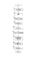
- Schematic diagram showing an example of the configuration of a molding facility for molding a cylindrical rubber member Block diagram showing functions of molding equipment control system Flow chart showing an example of a procedure when molding a cylindrical rubber member
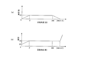
- Schematic showing how a cylindrical rubber member is molded (A) is a graph showing the relationship between the rotation angle of the molding drum and the rubber extrusion amount, and (b) is a graph showing the relationship between the rotation angle of the molding drum and the distance from the mold to the molding drum.
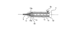
- FIG. 1 is a schematic diagram illustrating an example of a configuration of a molding facility for molding a cylindrical rubber member.
- the molding equipment shown in FIG. 1 includes an extruder 1, a gear pump 10, a mold 11, a molding drum (corresponding to a rotating support) 2, and a control device 3.
- the extruder 1 includes a cylindrical barrel 1a, a hopper 1b connected to a supply port of the barrel 1a, a screw 1c for kneading rubber and feeding it to the tip side, and a screw motor 1d for rotating the screw 1c. Have.
- the rotational speed of the screw motor 1d is controlled by the control device 3 as described later.
- the gear pump 10 is connected to the front end side of the extruder 1 in the extrusion direction, and the front end side of the gear pump 10 is connected to the mold 11.
- the rubber material kneaded by the extruder 1 is supplied to the gear pump 10, and the gear pump 10 supplies a predetermined amount of rubber to the mold 11.
- the rubber S is extruded from the mold 11 with a predetermined extrusion amount.
- the gear pump 10 has a pair of gears 10 a and has a function of feeding rubber toward the outlet 11 toward the mold 11.
- the pair of gears 10 a are driven to rotate by gear motors (not shown), and the number of rotations is controlled by the control device 3.
- the control device 3 By controlling the number of rotations of the gear motor and the number of rotations of the screw motor 1d by the control device 3, the amount of rubber S extruded from the mold 11 can be controlled.
- the pair of gears 10a are arranged in the vertical direction in FIG. 1, but may actually be arranged in the plane direction (the direction in which the rotation axis of the gear 10a is up and down in FIG. 1).
- a first pressure sensor 12 is provided on the inlet side of the gear pump 10, that is, on the side close to the extruder 1, and detects the pressure of rubber supplied from the extruder 1. Further, a second pressure sensor 13 is provided on the outlet side of the gear pump 10 to detect the pressure of the rubber S pushed out from the mold 11.
- the pressure on the inlet side of the gear pump 10 is determined by the amount of rubber fed by the gear 10a of the gear pump 10 and the screw 1c of the extruder 1. By keeping the pressure on the inlet side constant, the gear pump 10 can supply a fixed amount of rubber to the mold 11 and the amount of extrusion from the mold 11 is also stabilized. However, if the pressure on the inlet side is unstable, the amount of extrusion from the mold 11 varies, making it difficult to mold a cylindrical rubber member having a desired size.
- the molding method of the present invention includes a plurality of steps such as a preparation step, a winding start step, a winding step, and a winding end step, which will be described later, and the amount of rubber extrusion differs in each step.
- the PID control parameter in the winding process in which the rotation speed of the gear 10a is fixed and the rubber is continuously pushed out by a predetermined amount is the winding start in which the rotation amount of the gear 10a is greatly changed to greatly change the extrusion amount.
- the pressure on the inlet side cannot be kept constant.
- the PID control parameters are made different in each of the preparation process, the winding start process, the winding process, and the winding end process. More specifically, in the preparation step, the gear 10a is stopped without rotating, but nevertheless, the pressure on the inlet side needs to be kept constant. The amount of change is small. Therefore, parameters are determined so that PID control reacts to insensitivity.
- the gear 10a rotates at a high speed and the pressure on the inlet side needs to be kept constant, so the screw 1c also rotates at a high speed.
- the rubber gradually generates heat due to the kneading action, and the rubber viscosity also decreases.
- the pressure on the inlet side also seems to decrease, and PID control is performed so as to follow the influence of the disturbance in the high speed region so as to compensate for it.
- the amount of change in the rotation speed of the gear 10a is large, and the program operation is instantaneously performed from the stationary state to the high speed range. It is necessary to define a sensitive parameter that follows instantaneously.
- the winding end process is programmed so that the change of the gear 10a instantaneously decreases from the high speed range to the stationary state, contrary to the winding start process. Even in this case, in order to keep the pressure on the inlet side constant, it is necessary to determine a parameter that reacts sensitively so that the rotational speed of the screw 1c immediately follows. As a result, the pressure on the inlet side of the gear pump 10 can be kept substantially constant and stable in all steps.
- the example using what is called an external gear pump with which the gear pump 10 was connected to the extrusion direction front end side of the extruder 1 is shown.
- an extruder with a built-in gear pump in which a gear pump is built in the extruder may be used.
- the extruder with a built-in gear pump has a gear groove 1e at the tip of the screw 1c.
- the gear 10a of the gear pump 10 is configured to rotate, and the rotation of the gear pump 10 can be controlled only by controlling the rotation of the screw 1c, and the gear pump 10 can be pushed out in a fixed amount.
- the extruder with a built-in gear pump can more easily control the amount of extrusion compared to an extruder connected with an external gear pump, and a gear motor is unnecessary, so the tip of the extruder is more compact and more preferable. .
- the forming drum 2 is configured to be rotatable in the R direction by a servo motor 20 (see FIG. 2).
- the number of rotations of the servo motor 20 is controlled by the control device 3.
- the rubber extruded from the mold 11 is supplied to the molding drum 2, and the rubber is wound along the circumferential direction by rotating the molding drum 2 in the R direction with the rubber adhered. it can.
- a pressing roller (not shown) that presses the rubber supplied to the molding drum 2 may be provided.
- the control device 3 has a function of controlling the operation of each part of the molding facility.
- the screw motor control means 31 controls the rotational speed of the screw motor 1 d of the extruder 1 based on the pressure on the inlet side of the gear pump 10 detected by the first pressure sensor 12.
- the gear motor control means 32 controls the rotational speed of the gear motor 10b based on a predetermined control program (based on a time coefficient).
- the servo motor control means 33 controls the rotation speed of the servo motor 20.
- the extruder 1, the gear pump 10 and the mold 11 are configured so as to be movable forward and backward in the extrusion direction by the front / rear drive device 14, and can move toward and away from the forming drum 2. Such back-and-forth movement is also controlled by the front-rear drive device control means 34 of the control device 3.
- the method for molding a cylindrical rubber member according to the present invention includes a preparation step for bringing the mold 11 closer to the molding drum 2 and the rotation of the molding drum 2 at the same time as the extrusion of the rubber S from the approached mold 11 is started.
- the winding end of the wedge-shaped section is formed on the winding start portion by gradually decreasing the extrusion amount of the rubber S from the predetermined amount while keeping the distance from the molding drum 2 to the predetermined winding distance. Part And a step winding end to form.
- FIG. 3 is a flowchart showing an example of a procedure for molding a cylindrical rubber member.
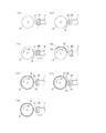
- FIG. 4 is a schematic view showing how a cylindrical rubber member is molded.
- FIG. 5A shows the relationship between the rotation angle of the molding drum 2 and the extrusion amount of the rubber S. Moreover, the relationship between the rotation angle of the molding drum 2 and the distance from the mold 11 to the molding drum 2 is shown in FIG.
- the extruder 1, the gear pump 10 and the mold 11 are moved forward together (# 1), and the mold 11 is brought close to the molding drum 2 as shown in FIG. At this time, the mold 11 is brought close to the surface of the molding drum 2 up to a predetermined distance D1. D1 is preferably 0.1 mm or less.
- the timing at which the mold 11 approaches the molding drum 2 is not particularly limited as long as the predetermined interval is provided before the rubber S is pushed out of the mold 11.
- the rubber material of the rubber S adjusted in the previous process is put into the hopper 1b of the extruder 1.
- the rubber material is not particularly limited.
- the rubber material is a general-purpose rubber raw material such as natural rubber, styrene-butadiene rubber (SBR), butadiene rubber (BR), isoprene rubber (IR), etc. And prepared by kneading and heat crosslinking.
- SBR styrene-butadiene rubber
- BR butadiene rubber
- IR isoprene rubber
- the rubber material thrown into the hopper 1b is kneaded by the screw 1c of the extruder 1, sent to the front end side in the extrusion direction, and supplied to the gear pump 10 (# 2, 3).
- the rubber material supplied to the gear pump 10 is sent out toward the mold 11 toward the outlet side by a pair of rotating gears 10a (# 4).
- the rubber material supplied to the mold 11 is pushed out as rubber S from the opening of the mold 11 (# 5).
- FIG. 4B when the tip of the extruded rubber S sticks to the outer surface of the molding drum 2 and is fixed, the rotation of the molding drum 2 is performed as shown in FIG. Driving is started (# 6). Actually, the extrusion of the rubber S from the mold 11 is started (or substantially simultaneously), and the rotation of the molding drum 2 is started.
- the amount of rubber S extruded from the mold 11 is gradually increased to a predetermined amount by controlling the rotational speed of the gear 10a and the rotational speed of the screw 1c. (# 7). Further, as the amount of rubber S pushed out increases, the mold 11 is gradually retracted as shown in FIG. 4C to gradually increase the distance of the mold 11 from the molding drum 2 (# 7). Thereby, the winding start part S1 of rubber
- the rubber S extrusion amount is gradually increased to a predetermined amount Q1 until the rotation angle of the molding drum 2 reaches ⁇ degrees.
- the mold 11 is gradually retracted until the rotation angle of the molding drum 2 reaches ⁇ degrees, and the distance of the mold 11 from the molding drum 2 is gradually increased from D1 to a predetermined distance D2. Make it bigger.
- the extrusion amount of the rubber S is maintained at the predetermined amount Q1, and the molding drum 2 is continuously driven to rotate while the distance from the molding drum 2 of the mold 11 is maintained at the predetermined distance D2.
- the predetermined distance D2 corresponds to a desired thickness of the cylindrical rubber member to be molded, and the extruded rubber S passes through the gap between the mold 11 and the surface of the molding drum 2 and becomes the thickness of D2. .
- the winding start part S1 becomes cross-sectional wedge shape, and rubber
- the extrusion amount of the rubber S is maintained at a predetermined amount Q1, and the rotation angle becomes (360 + ⁇ ) degrees.
- the extrusion amount of the rubber S is gradually decreased from the predetermined amount Q1.
- the distance from the molding drum 2 of the mold 11 is maintained at a predetermined distance D2.
- the rubber S is formed such that the winding end portion S2 has a wedge shape in cross section, and the winding end portion S2 is overlapped on the winding start portion S1.
- the cylindrical rubber member in which the thickness of the joint portion between the winding start portion S1 and the winding end portion S2 is substantially the same as the thickness of the other portions is molded.
- the extruder 1 is moved back and forth to move closer to or away from the forming drum 2, but the forming drum 2 is moved back and forth to move closer to or away from the extruder 1. It does not matter.
Landscapes
- Engineering & Computer Science (AREA)
- Mechanical Engineering (AREA)
- Extrusion Moulding Of Plastics Or The Like (AREA)
- Tyre Moulding (AREA)
Priority Applications (2)
| Application Number | Priority Date | Filing Date | Title |
|---|---|---|---|
| CN201380004055.3A CN103958158B (zh) | 2012-04-16 | 2013-03-19 | 圆筒状橡胶构件的成形方法 |
| US14/369,992 US10005206B2 (en) | 2012-04-16 | 2013-03-19 | Method for forming cylindrical rubber member |
Applications Claiming Priority (2)
| Application Number | Priority Date | Filing Date | Title |
|---|---|---|---|
| JP2012-092853 | 2012-04-16 | ||
| JP2012092853A JP5989387B2 (ja) | 2012-04-16 | 2012-04-16 | 円筒状ゴム部材の成形方法 |
Publications (1)
| Publication Number | Publication Date |
|---|---|
| WO2013157343A1 true WO2013157343A1 (fr) | 2013-10-24 |
Family
ID=49383310
Family Applications (1)
| Application Number | Title | Priority Date | Filing Date |
|---|---|---|---|
| PCT/JP2013/057897 Ceased WO2013157343A1 (fr) | 2012-04-16 | 2013-03-19 | Procédé de moulage d'élément cylindrique en caoutchouc |
Country Status (4)
| Country | Link |
|---|---|
| US (1) | US10005206B2 (fr) |
| JP (1) | JP5989387B2 (fr) |
| CN (1) | CN103958158B (fr) |
| WO (1) | WO2013157343A1 (fr) |
Families Citing this family (5)
| Publication number | Priority date | Publication date | Assignee | Title |
|---|---|---|---|---|
| JP6324846B2 (ja) * | 2014-08-26 | 2018-05-16 | 東洋ゴム工業株式会社 | ゴム部材の製造装置及び製造方法 |
| JP6511295B2 (ja) * | 2015-03-05 | 2019-05-15 | Toyo Tire株式会社 | ゴム部材の成形方法及び成形装置 |
| JP7198151B2 (ja) | 2019-05-17 | 2022-12-28 | Toyo Tire株式会社 | 帯状ゴム部材の成形方法及び成形装置 |
| CN110815755A (zh) * | 2019-12-12 | 2020-02-21 | 软控股份有限公司 | 一种挤出机及一种型胶生产装置 |
| JP7635093B2 (ja) * | 2021-07-27 | 2025-02-25 | Toyo Tire株式会社 | ゴム部材成形方法、ゴム部材成形装置、成形ドラム、及びプログラム |
Citations (3)
| Publication number | Priority date | Publication date | Assignee | Title |
|---|---|---|---|---|
| JP2008023847A (ja) * | 2006-07-21 | 2008-02-07 | Toyo Seikan Kaisha Ltd | 押出成形方法と押出成形装置 |
| JP2010234707A (ja) * | 2009-03-31 | 2010-10-21 | Toyo Tire & Rubber Co Ltd | タイヤ成形方法 |
| JP2011173369A (ja) * | 2010-02-25 | 2011-09-08 | Bridgestone Corp | ビード部材の製造装置及び製造方法 |
Family Cites Families (5)
| Publication number | Priority date | Publication date | Assignee | Title |
|---|---|---|---|---|
| JPH0671587A (ja) | 1992-08-26 | 1994-03-15 | Bridgestone Corp | 押出トレッドの才断方法、押出トレッドの才断装置及び押出トレッドの引張装置 |
| JP5013636B2 (ja) | 2000-05-24 | 2012-08-29 | 株式会社ブリヂストン | タイヤ構成部材の成形方法 |
| JP4363511B2 (ja) | 2002-08-26 | 2009-11-11 | 横浜ゴム株式会社 | 円筒状ゴム部材の製造方法及びその装置 |
| JP5225869B2 (ja) * | 2007-09-18 | 2013-07-03 | 東洋ゴム工業株式会社 | ゴムストリップ材の成形装置及びゴムストリップ材の成形方法 |
| WO2009078247A1 (fr) * | 2007-12-14 | 2009-06-25 | Bridgestone Corporation | Procédé et dispositif de production d'élément en caoutchouc |
-
2012
- 2012-04-16 JP JP2012092853A patent/JP5989387B2/ja not_active Expired - Fee Related
-
2013
- 2013-03-19 WO PCT/JP2013/057897 patent/WO2013157343A1/fr not_active Ceased
- 2013-03-19 CN CN201380004055.3A patent/CN103958158B/zh not_active Expired - Fee Related
- 2013-03-19 US US14/369,992 patent/US10005206B2/en active Active
Patent Citations (3)
| Publication number | Priority date | Publication date | Assignee | Title |
|---|---|---|---|---|
| JP2008023847A (ja) * | 2006-07-21 | 2008-02-07 | Toyo Seikan Kaisha Ltd | 押出成形方法と押出成形装置 |
| JP2010234707A (ja) * | 2009-03-31 | 2010-10-21 | Toyo Tire & Rubber Co Ltd | タイヤ成形方法 |
| JP2011173369A (ja) * | 2010-02-25 | 2011-09-08 | Bridgestone Corp | ビード部材の製造装置及び製造方法 |
Also Published As
| Publication number | Publication date |
|---|---|
| JP2013220569A (ja) | 2013-10-28 |
| US10005206B2 (en) | 2018-06-26 |
| JP5989387B2 (ja) | 2016-09-07 |
| CN103958158A (zh) | 2014-07-30 |
| US20150008618A1 (en) | 2015-01-08 |
| CN103958158B (zh) | 2016-02-10 |
Similar Documents
| Publication | Publication Date | Title |
|---|---|---|
| JP5651504B2 (ja) | シート状ゴム成形装置及び方法 | |
| JP5989387B2 (ja) | 円筒状ゴム部材の成形方法 | |
| US20090311358A1 (en) | Integrated apparatus having kneading part and injecting part | |
| JP5313741B2 (ja) | タイヤ成形方法 | |
| CN104936759A (zh) | 用于挤出弹性体混合物的装置和方法 | |
| CN107303737A (zh) | 胎圈芯包覆方法及胎圈芯包覆装置 | |
| JP6644626B2 (ja) | ビードコア被覆方法及びビードコア被覆装置 | |
| JP4567428B2 (ja) | ゴム部材成形設備及びゴム材料成形方法 | |
| CN104416933A (zh) | 充气轮胎的成形装置及成形方法 | |
| JP2004358738A (ja) | ストリップゴム連続成型設備及び連続成型方法 | |
| JP4534225B2 (ja) | ゴム部材成形設備及びゴム部材成形方法 | |
| JP6511295B2 (ja) | ゴム部材の成形方法及び成形装置 | |
| WO2006046354A1 (fr) | Appareil et procede pour mouler un element en caoutchouc | |
| JP2004090301A (ja) | 射出成形機からの帯状ゴム材料巻取り制御方法と射出成形機を備えたタイヤ成形システム | |
| US11975472B2 (en) | Method for forming belt-like rubber member | |
| JP2018047561A (ja) | 円筒状ゴム部材の成形方法 | |
| JP2018024170A (ja) | ゴム部材の成形装置及び成形方法 | |
| JP7138079B2 (ja) | ビードコア被覆方法及びビードコア被覆装置 | |
| JP6741515B2 (ja) | ビードコア被覆方法及びビードコア被覆装置 | |
| JP2014000722A (ja) | 環状ゴム部材の成形方法および環状ゴム部材の成形設備 | |
| JP2008018571A (ja) | ダイヘッド、ゴム押出機及びストリップゴム巻付装置 | |
| WO2008001432A1 (fr) | Procédé de production de pneumatique par extrusion volumique | |
| JP2012051159A (ja) | 未加硫タイヤの製造装置および未加硫タイヤの製造方法 | |
| JP2009137034A (ja) | ストリップゴム押出装置及びストリップゴム押出方法 | |
| JP4535884B2 (ja) | 複合押出機の押出制御方法 |
Legal Events
| Date | Code | Title | Description |
|---|---|---|---|
| 121 | Ep: the epo has been informed by wipo that ep was designated in this application |
Ref document number: 13778940 Country of ref document: EP Kind code of ref document: A1 |
|
| WWE | Wipo information: entry into national phase |
Ref document number: 14369992 Country of ref document: US |
|
| NENP | Non-entry into the national phase |
Ref country code: DE |
|
| 122 | Ep: pct application non-entry in european phase |
Ref document number: 13778940 Country of ref document: EP Kind code of ref document: A1 |