WO2013157375A1 - Unité d'embrayage - Google Patents
Unité d'embrayage Download PDFInfo
- Publication number
- WO2013157375A1 WO2013157375A1 PCT/JP2013/059641 JP2013059641W WO2013157375A1 WO 2013157375 A1 WO2013157375 A1 WO 2013157375A1 JP 2013059641 W JP2013059641 W JP 2013059641W WO 2013157375 A1 WO2013157375 A1 WO 2013157375A1
- Authority
- WO
- WIPO (PCT)
- Prior art keywords
- clutch
- engagement
- input
- brake
- rotational torque
- Prior art date
- Legal status (The legal status is an assumption and is not a legal conclusion. Google has not performed a legal analysis and makes no representation as to the accuracy of the status listed.)
- Ceased
Links
Images
















Classifications
-
- F—MECHANICAL ENGINEERING; LIGHTING; HEATING; WEAPONS; BLASTING
- F16—ENGINEERING ELEMENTS AND UNITS; GENERAL MEASURES FOR PRODUCING AND MAINTAINING EFFECTIVE FUNCTIONING OF MACHINES OR INSTALLATIONS; THERMAL INSULATION IN GENERAL
- F16D—COUPLINGS FOR TRANSMITTING ROTATION; CLUTCHES; BRAKES
- F16D67/00—Combinations of couplings and brakes; Combinations of clutches and brakes
- F16D67/02—Clutch-brake combinations
-
- B—PERFORMING OPERATIONS; TRANSPORTING
- B60—VEHICLES IN GENERAL
- B60N—SEATS SPECIALLY ADAPTED FOR VEHICLES; VEHICLE PASSENGER ACCOMMODATION NOT OTHERWISE PROVIDED FOR
- B60N2/00—Seats specially adapted for vehicles; Arrangement or mounting of seats in vehicles
- B60N2/02—Seats specially adapted for vehicles; Arrangement or mounting of seats in vehicles the seat or part thereof being movable, e.g. adjustable
- B60N2/04—Seats specially adapted for vehicles; Arrangement or mounting of seats in vehicles the seat or part thereof being movable, e.g. adjustable the whole seat being movable
- B60N2/16—Seats specially adapted for vehicles; Arrangement or mounting of seats in vehicles the seat or part thereof being movable, e.g. adjustable the whole seat being movable height-adjustable
- B60N2/1635—Seats specially adapted for vehicles; Arrangement or mounting of seats in vehicles the seat or part thereof being movable, e.g. adjustable the whole seat being movable height-adjustable characterised by the drive mechanism
- B60N2/165—Gear wheel driven mechanism
-
- B—PERFORMING OPERATIONS; TRANSPORTING
- B60—VEHICLES IN GENERAL
- B60N—SEATS SPECIALLY ADAPTED FOR VEHICLES; VEHICLE PASSENGER ACCOMMODATION NOT OTHERWISE PROVIDED FOR
- B60N2/00—Seats specially adapted for vehicles; Arrangement or mounting of seats in vehicles
- B60N2/02—Seats specially adapted for vehicles; Arrangement or mounting of seats in vehicles the seat or part thereof being movable, e.g. adjustable
- B60N2/04—Seats specially adapted for vehicles; Arrangement or mounting of seats in vehicles the seat or part thereof being movable, e.g. adjustable the whole seat being movable
- B60N2/16—Seats specially adapted for vehicles; Arrangement or mounting of seats in vehicles the seat or part thereof being movable, e.g. adjustable the whole seat being movable height-adjustable
- B60N2/1635—Seats specially adapted for vehicles; Arrangement or mounting of seats in vehicles the seat or part thereof being movable, e.g. adjustable the whole seat being movable height-adjustable characterised by the drive mechanism
- B60N2/167—Ratchet mechanism
-
- B—PERFORMING OPERATIONS; TRANSPORTING
- B60—VEHICLES IN GENERAL
- B60N—SEATS SPECIALLY ADAPTED FOR VEHICLES; VEHICLE PASSENGER ACCOMMODATION NOT OTHERWISE PROVIDED FOR
- B60N2/00—Seats specially adapted for vehicles; Arrangement or mounting of seats in vehicles
- B60N2/02—Seats specially adapted for vehicles; Arrangement or mounting of seats in vehicles the seat or part thereof being movable, e.g. adjustable
- B60N2/04—Seats specially adapted for vehicles; Arrangement or mounting of seats in vehicles the seat or part thereof being movable, e.g. adjustable the whole seat being movable
- B60N2/16—Seats specially adapted for vehicles; Arrangement or mounting of seats in vehicles the seat or part thereof being movable, e.g. adjustable the whole seat being movable height-adjustable
- B60N2/168—Seats specially adapted for vehicles; Arrangement or mounting of seats in vehicles the seat or part thereof being movable, e.g. adjustable the whole seat being movable height-adjustable and provided with braking systems
-
- B—PERFORMING OPERATIONS; TRANSPORTING
- B60—VEHICLES IN GENERAL
- B60N—SEATS SPECIALLY ADAPTED FOR VEHICLES; VEHICLE PASSENGER ACCOMMODATION NOT OTHERWISE PROVIDED FOR
- B60N2/00—Seats specially adapted for vehicles; Arrangement or mounting of seats in vehicles
- B60N2/02—Seats specially adapted for vehicles; Arrangement or mounting of seats in vehicles the seat or part thereof being movable, e.g. adjustable
- B60N2/04—Seats specially adapted for vehicles; Arrangement or mounting of seats in vehicles the seat or part thereof being movable, e.g. adjustable the whole seat being movable
- B60N2/16—Seats specially adapted for vehicles; Arrangement or mounting of seats in vehicles the seat or part thereof being movable, e.g. adjustable the whole seat being movable height-adjustable
- B60N2/169—Stepwise movement mechanisms, e.g. ratchets
-
- B—PERFORMING OPERATIONS; TRANSPORTING
- B60—VEHICLES IN GENERAL
- B60N—SEATS SPECIALLY ADAPTED FOR VEHICLES; VEHICLE PASSENGER ACCOMMODATION NOT OTHERWISE PROVIDED FOR
- B60N2/00—Seats specially adapted for vehicles; Arrangement or mounting of seats in vehicles
- B60N2/02—Seats specially adapted for vehicles; Arrangement or mounting of seats in vehicles the seat or part thereof being movable, e.g. adjustable
- B60N2/04—Seats specially adapted for vehicles; Arrangement or mounting of seats in vehicles the seat or part thereof being movable, e.g. adjustable the whole seat being movable
- B60N2/16—Seats specially adapted for vehicles; Arrangement or mounting of seats in vehicles the seat or part thereof being movable, e.g. adjustable the whole seat being movable height-adjustable
- B60N2/18—Seats specially adapted for vehicles; Arrangement or mounting of seats in vehicles the seat or part thereof being movable, e.g. adjustable the whole seat being movable height-adjustable the front or the rear portion of the seat being adjustable, e.g. independently of each other
- B60N2/1807—Seats specially adapted for vehicles; Arrangement or mounting of seats in vehicles the seat or part thereof being movable, e.g. adjustable the whole seat being movable height-adjustable the front or the rear portion of the seat being adjustable, e.g. independently of each other characterised by the cinematic
- B60N2/181—Rods
- B60N2/1814—Parallelogram-like structure
-
- B—PERFORMING OPERATIONS; TRANSPORTING
- B60—VEHICLES IN GENERAL
- B60N—SEATS SPECIALLY ADAPTED FOR VEHICLES; VEHICLE PASSENGER ACCOMMODATION NOT OTHERWISE PROVIDED FOR
- B60N2/00—Seats specially adapted for vehicles; Arrangement or mounting of seats in vehicles
- B60N2/02—Seats specially adapted for vehicles; Arrangement or mounting of seats in vehicles the seat or part thereof being movable, e.g. adjustable
- B60N2/04—Seats specially adapted for vehicles; Arrangement or mounting of seats in vehicles the seat or part thereof being movable, e.g. adjustable the whole seat being movable
- B60N2/16—Seats specially adapted for vehicles; Arrangement or mounting of seats in vehicles the seat or part thereof being movable, e.g. adjustable the whole seat being movable height-adjustable
- B60N2/18—Seats specially adapted for vehicles; Arrangement or mounting of seats in vehicles the seat or part thereof being movable, e.g. adjustable the whole seat being movable height-adjustable the front or the rear portion of the seat being adjustable, e.g. independently of each other
- B60N2/185—Seats specially adapted for vehicles; Arrangement or mounting of seats in vehicles the seat or part thereof being movable, e.g. adjustable the whole seat being movable height-adjustable the front or the rear portion of the seat being adjustable, e.g. independently of each other characterised by the drive mechanism
- B60N2/1882—Ratchet mechanism
-
- B—PERFORMING OPERATIONS; TRANSPORTING
- B60—VEHICLES IN GENERAL
- B60N—SEATS SPECIALLY ADAPTED FOR VEHICLES; VEHICLE PASSENGER ACCOMMODATION NOT OTHERWISE PROVIDED FOR
- B60N2/00—Seats specially adapted for vehicles; Arrangement or mounting of seats in vehicles
- B60N2/02—Seats specially adapted for vehicles; Arrangement or mounting of seats in vehicles the seat or part thereof being movable, e.g. adjustable
- B60N2/04—Seats specially adapted for vehicles; Arrangement or mounting of seats in vehicles the seat or part thereof being movable, e.g. adjustable the whole seat being movable
- B60N2/16—Seats specially adapted for vehicles; Arrangement or mounting of seats in vehicles the seat or part thereof being movable, e.g. adjustable the whole seat being movable height-adjustable
- B60N2/18—Seats specially adapted for vehicles; Arrangement or mounting of seats in vehicles the seat or part thereof being movable, e.g. adjustable the whole seat being movable height-adjustable the front or the rear portion of the seat being adjustable, e.g. independently of each other
- B60N2/1892—Seats specially adapted for vehicles; Arrangement or mounting of seats in vehicles the seat or part thereof being movable, e.g. adjustable the whole seat being movable height-adjustable the front or the rear portion of the seat being adjustable, e.g. independently of each other characterised by a lock
-
- B—PERFORMING OPERATIONS; TRANSPORTING
- B60—VEHICLES IN GENERAL
- B60N—SEATS SPECIALLY ADAPTED FOR VEHICLES; VEHICLE PASSENGER ACCOMMODATION NOT OTHERWISE PROVIDED FOR
- B60N2/00—Seats specially adapted for vehicles; Arrangement or mounting of seats in vehicles
- B60N2/02—Seats specially adapted for vehicles; Arrangement or mounting of seats in vehicles the seat or part thereof being movable, e.g. adjustable
- B60N2/04—Seats specially adapted for vehicles; Arrangement or mounting of seats in vehicles the seat or part thereof being movable, e.g. adjustable the whole seat being movable
- B60N2/16—Seats specially adapted for vehicles; Arrangement or mounting of seats in vehicles the seat or part thereof being movable, e.g. adjustable the whole seat being movable height-adjustable
- B60N2/18—Seats specially adapted for vehicles; Arrangement or mounting of seats in vehicles the seat or part thereof being movable, e.g. adjustable the whole seat being movable height-adjustable the front or the rear portion of the seat being adjustable, e.g. independently of each other
- B60N2/1896—Stepwise movement mechanisms, e.g. ratchets
-
- F—MECHANICAL ENGINEERING; LIGHTING; HEATING; WEAPONS; BLASTING
- F16—ENGINEERING ELEMENTS AND UNITS; GENERAL MEASURES FOR PRODUCING AND MAINTAINING EFFECTIVE FUNCTIONING OF MACHINES OR INSTALLATIONS; THERMAL INSULATION IN GENERAL
- F16D—COUPLINGS FOR TRANSMITTING ROTATION; CLUTCHES; BRAKES
- F16D3/00—Yielding couplings, i.e. with means permitting movement between the connected parts during the drive
- F16D3/02—Yielding couplings, i.e. with means permitting movement between the connected parts during the drive adapted to specific functions
-
- F—MECHANICAL ENGINEERING; LIGHTING; HEATING; WEAPONS; BLASTING
- F16—ENGINEERING ELEMENTS AND UNITS; GENERAL MEASURES FOR PRODUCING AND MAINTAINING EFFECTIVE FUNCTIONING OF MACHINES OR INSTALLATIONS; THERMAL INSULATION IN GENERAL
- F16D—COUPLINGS FOR TRANSMITTING ROTATION; CLUTCHES; BRAKES
- F16D3/00—Yielding couplings, i.e. with means permitting movement between the connected parts during the drive
- F16D3/50—Yielding couplings, i.e. with means permitting movement between the connected parts during the drive with the coupling parts connected by one or more intermediate members
-
- F—MECHANICAL ENGINEERING; LIGHTING; HEATING; WEAPONS; BLASTING
- F16—ENGINEERING ELEMENTS AND UNITS; GENERAL MEASURES FOR PRODUCING AND MAINTAINING EFFECTIVE FUNCTIONING OF MACHINES OR INSTALLATIONS; THERMAL INSULATION IN GENERAL
- F16D—COUPLINGS FOR TRANSMITTING ROTATION; CLUTCHES; BRAKES
- F16D41/00—Freewheels or freewheel clutches
- F16D41/06—Freewheels or freewheel clutches with intermediate wedging coupling members between an inner and an outer surface
- F16D41/08—Freewheels or freewheel clutches with intermediate wedging coupling members between an inner and an outer surface with provision for altering the freewheeling action
- F16D41/10—Freewheels or freewheel clutches with intermediate wedging coupling members between an inner and an outer surface with provision for altering the freewheeling action with self-actuated reversing
- F16D41/105—Freewheels or freewheel clutches with intermediate wedging coupling members between an inner and an outer surface with provision for altering the freewheeling action with self-actuated reversing the intermediate members being of circular cross-section, of only one size and wedging by rolling movement not having an axial component between inner and outer races, one of which is cylindrical
-
- F—MECHANICAL ENGINEERING; LIGHTING; HEATING; WEAPONS; BLASTING
- F16—ENGINEERING ELEMENTS AND UNITS; GENERAL MEASURES FOR PRODUCING AND MAINTAINING EFFECTIVE FUNCTIONING OF MACHINES OR INSTALLATIONS; THERMAL INSULATION IN GENERAL
- F16D—COUPLINGS FOR TRANSMITTING ROTATION; CLUTCHES; BRAKES
- F16D41/00—Freewheels or freewheel clutches
- F16D41/18—Freewheels or freewheel clutches with non-hinged detent
-
- F—MECHANICAL ENGINEERING; LIGHTING; HEATING; WEAPONS; BLASTING
- F16—ENGINEERING ELEMENTS AND UNITS; GENERAL MEASURES FOR PRODUCING AND MAINTAINING EFFECTIVE FUNCTIONING OF MACHINES OR INSTALLATIONS; THERMAL INSULATION IN GENERAL
- F16D—COUPLINGS FOR TRANSMITTING ROTATION; CLUTCHES; BRAKES
- F16D63/00—Brakes not otherwise provided for; Brakes combining more than one of the types of groups F16D49/00 - F16D61/00
- F16D63/006—Positive locking brakes
-
- F—MECHANICAL ENGINEERING; LIGHTING; HEATING; WEAPONS; BLASTING
- F16—ENGINEERING ELEMENTS AND UNITS; GENERAL MEASURES FOR PRODUCING AND MAINTAINING EFFECTIVE FUNCTIONING OF MACHINES OR INSTALLATIONS; THERMAL INSULATION IN GENERAL
- F16D—COUPLINGS FOR TRANSMITTING ROTATION; CLUTCHES; BRAKES
- F16D2127/00—Auxiliary mechanisms
- F16D2127/06—Locking mechanisms, e.g. acting on actuators, on release mechanisms or on force transmission mechanisms
Definitions
- the present invention relates to a lever side clutch portion to which rotational torque is input by lever operation, and a brake side for transmitting rotational torque from the lever side clutch portion to the output side and blocking rotational torque reversely input from the output side.
- the present invention relates to a clutch unit including a clutch unit.
- the present applicant for example, is incorporated in an automobile seat lifter portion that adjusts the seat seat up and down by lever operation, and the rotational torque from the lever side clutch portion is inputted by the lever operation.
- a clutch unit that includes a brake-side clutch portion that transmits to the output side and blocks rotational torque that is reversely input from the output side has been proposed (see, for example, Patent Document 1).
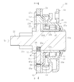
- FIG. 32 is a cross-sectional view showing the overall configuration of the conventional clutch unit disclosed in Patent Document 1 described above.
- FIG. 33 shows the lever side clutch portion in a cross section taken along line EE of FIG.
- FIG. 34 shows a brake side clutch portion in a cross section taken along line FF in FIG.
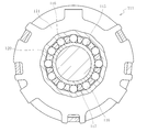
- the lever-side clutch unit 111 transmits to the brake-side clutch unit 112 the lever-side outer ring 114 to which the rotation torque is input by the lever operation and the rotation torque from the lever-side outer ring 114.
- the brake side clutch portion 112 when rotational torque is input from the lever side clutch portion 111 to the inner ring 115, the inner ring 115 comes into contact with the cylindrical roller 127 and presses against the elastic force of the leaf spring 128. As a result, the cylindrical roller 127 is detached from the wedge clearance 126 between the brake-side outer ring 123 and the output shaft 122, and the output shaft 122 can rotate. As the inner ring 115 further rotates, rotational torque from the inner ring 115 is transmitted to the output shaft 122, and the output shaft 122 rotates.
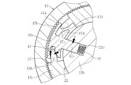
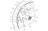
- the engagement element in the present invention preferably has a structure that can be engaged and disengaged between the stationary member and the output member by displacement in the radial direction.
- engagement and disengagement between both members is enabled by displacement in the radial direction, engagement and disengagement of the engagement element with respect to the stationary member can be easily performed by meshing and releasing the concave and convex portions.
- the concavo-convex portion preferably has a structure that has any one shape selected from a mountain shape, a rectangular shape, and a tooth shape.
- the cam portion in the present invention is configured by a tapered surface formed on at least one of the engagement element or the input member. If the cam portion is configured by the engaging member or the tapered surface of the input member in this way, it is easy to displace the engaging member against the elastic force of the elastic member in the direction in which the engaging member is detached from the stationary member.
- the output side clutch portion in the present invention is a kind of two types of one-way clutches, wherein each of the two types of one-way clutches transmits the rotational torque in both forward and reverse directions from the input side clutch portion to the output side.
- Only the one-way clutch can be constituted by a bidirectional clutch that blocks the rotational torque in either the forward or reverse direction, which is reversely input from the output side, by the engagement of the concave and convex portions.
- the engagement of the concavo-convex portion in one type of one-way clutch and the engagement of the concavo-convex portion in another type of one-way clutch can cause any rotational torque in the forward and reverse directions between the stationary member and the output member.
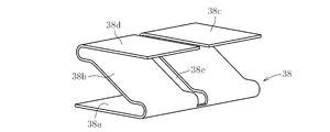
- the bidirectional clutch according to the present invention preferably has a structure in which an elastic member of one kind of one-way clutch and an elastic member of another kind of one-way clutch are shared by two kinds of one-way clutches. In this way, since one elastic member can be shared by two types of one-way clutches, the number of parts can be reduced and the assembly workability can be improved, and the cost of the entire clutch unit can be easily reduced.
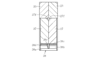
- the bidirectional clutch according to the present invention is chamfered at either one of the edge part contacting the stationary member of the two kinds of engaging members arranged in parallel in the axial direction or the edge part contacting the engaging member of the two kinds of stationary members.
- a structure in which is formed is desirable. In this way, in the two types of one-way clutches arranged side by side in the axial direction, even if the engagement element of any one type of one-way clutch moves in the axial direction, Since interference with the stationary member or the engaging element can be suppressed, the two types of one-way clutches can be operated smoothly.
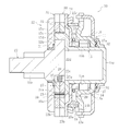
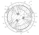
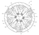
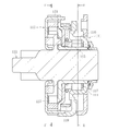
- a cylindrical roller 16 provided, a cage 17 that holds the plurality of cylindrical rollers 16 at equal intervals in the circumferential direction, an inner centering spring 18 for returning the cage 17 to a neutral state, and a lever-side outer ring 14 And an outer centering spring 19 for returning to the neutral state.
- a resin friction ring 31 is fixed to the brake side plate 25, and the friction ring 31 is press-fitted into the output shaft 22 with a predetermined tightening allowance, so that it is interposed between the outer peripheral surface of the output shaft 22.
- a rotational resistance is applied to the output shaft 22 by the generated frictional force.
- the brake side clutch portion 12 is a portion to which a larger impact load is applied at the time of a vehicle collision than the lever side clutch portion 11.
- the slippage of the engagement element 27 does not occur, so that it is easy to increase the torque capacity with respect to the impact load.
- the inner ring 15, the output shaft 22 and the coil spring 28 are used as one member common to the two one-way clutches 50 and 51, and the engagement elements 27 and 37 and the brake side outer rings 23 and 33 are two.
- One one-way clutch 50, 51 is provided separately.
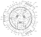
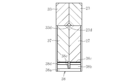
- the engaging elements 27 and 37 are formed with the concavo-convex parts 27a and 37a only on one side (the side in contact with the column part 15c of the inner ring 15) with respect to the radial center line. Concave portions 27a and 37a are not formed on one side (the side not in contact with the column portion 15c of the inner ring 15), and the circular arc surfaces 27d and 37d are formed.
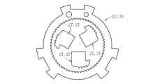
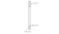
- FIG. 12A and FIG. 12B they are fitted to the abutting surfaces 23g, 33g of both brake-side outer rings 23, 33 in a state in which the direction of shutting off the rotational torque due to the engagement of the concave and convex portions 23a, 33a is reversed.
- a set of protrusions 23e, 33e and holes 23f, 33f are provided.
- the protrusions 23e and 33e and the holes 23f and 33f are disposed at line symmetrical positions with respect to the center line L of the brake side outer rings 23 and 33.
- a divided structure is also possible.
- the cam portion 49 is constituted by the engagement element 47 or the tapered surfaces 47e and 15i of the inner ring 15, so that the engagement element 47 is displaced against the elastic force of the coil spring 48 in the direction in which the engagement element 47 is detached from the brake side outer ring 43. It becomes easy.
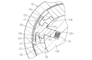
- the uneven portions 43a and 47a may be rectangular uneven portions 43a and 47a as shown in FIG.
- the uneven parts 43a and 47a may be rectangular uneven portions 43a and 47a as shown in FIG.
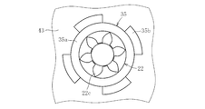
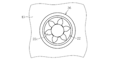
- the friction ring 36 can also employ a sliding bearing as shown in FIG. This sliding bearing can be employed as the friction ring 36 because the friction coefficient differs between the outer peripheral surface and the inner peripheral surface.
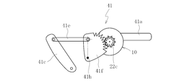
- FIG. 29 shows a seat seat 40 installed in a passenger compartment of an automobile.
- the seat 40 includes a seat 40a and a backrest 40b, and includes a seat lifter 41 that adjusts the height H of the seat 40a.
- the height H of the seating seat 40a is adjusted by the operation lever 41a of the seat lifter 41.
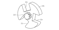
- the pinion gear 22c is integrally formed at the tip of the shaft portion 22a of the output shaft 22 as shown in FIG.
Landscapes
- Engineering & Computer Science (AREA)
- Mechanical Engineering (AREA)
- Aviation & Aerospace Engineering (AREA)
- Transportation (AREA)
- General Engineering & Computer Science (AREA)
- Braking Arrangements (AREA)
- One-Way And Automatic Clutches, And Combinations Of Different Clutches (AREA)
Priority Applications (4)
| Application Number | Priority Date | Filing Date | Title |
|---|---|---|---|
| KR1020147030202A KR102043668B1 (ko) | 2012-04-20 | 2013-03-29 | 클러치 유닛 |
| US14/391,184 US9541147B2 (en) | 2012-04-20 | 2013-03-29 | Clutch unit |
| CN201380020614.XA CN104246265B (zh) | 2012-04-20 | 2013-03-29 | 离合器单元 |
| EP13778896.4A EP2840275B1 (fr) | 2012-04-20 | 2013-03-29 | Unité d'embrayage |
Applications Claiming Priority (4)
| Application Number | Priority Date | Filing Date | Title |
|---|---|---|---|
| JP2012096612A JP5944213B2 (ja) | 2012-04-20 | 2012-04-20 | クラッチユニット |
| JP2012-096612 | 2012-04-20 | ||
| JP2012-277874 | 2012-12-20 | ||
| JP2012277874A JP6116890B2 (ja) | 2012-12-20 | 2012-12-20 | クラッチユニット |
Publications (1)
| Publication Number | Publication Date |
|---|---|
| WO2013157375A1 true WO2013157375A1 (fr) | 2013-10-24 |
Family
ID=49383340
Family Applications (1)
| Application Number | Title | Priority Date | Filing Date |
|---|---|---|---|
| PCT/JP2013/059641 Ceased WO2013157375A1 (fr) | 2012-04-20 | 2013-03-29 | Unité d'embrayage |
Country Status (5)
| Country | Link |
|---|---|
| US (1) | US9541147B2 (fr) |
| EP (1) | EP2840275B1 (fr) |
| KR (1) | KR102043668B1 (fr) |
| CN (1) | CN104246265B (fr) |
| WO (1) | WO2013157375A1 (fr) |
Cited By (1)
| Publication number | Priority date | Publication date | Assignee | Title |
|---|---|---|---|---|
| CN112833113A (zh) * | 2021-02-07 | 2021-05-25 | 深圳市正德智控股份有限公司 | 一种齿轮箱用离合机构及齿轮传动电动机 |
Families Citing this family (29)
| Publication number | Priority date | Publication date | Assignee | Title |
|---|---|---|---|---|
| US9616785B2 (en) * | 2014-01-09 | 2017-04-11 | PAC Seating Systems, Inc. | Infinitely vertically adjustable drop down armrest mechanism |
| DE202015103313U1 (de) * | 2015-06-24 | 2016-09-30 | Jörg Schwarzbich | Sitzversteller |
| JP2017065484A (ja) * | 2015-09-30 | 2017-04-06 | アイシン精機株式会社 | 車両用シートリフター装置 |
| JP6665000B2 (ja) * | 2016-03-18 | 2020-03-13 | Ntn株式会社 | クラッチユニット |
| JP6636366B2 (ja) * | 2016-03-22 | 2020-01-29 | Ntn株式会社 | クラッチユニット |
| KR101835524B1 (ko) * | 2016-06-29 | 2018-03-08 | 주식회사 다스 | 자동차 시트의 높이 조절장치 |
| KR101974247B1 (ko) * | 2016-07-11 | 2019-04-30 | 현경열 | 일방향 클러치 |
| JP6789726B2 (ja) * | 2016-08-30 | 2020-11-25 | Ntn株式会社 | クラッチユニット |
| US10625633B2 (en) * | 2016-11-22 | 2020-04-21 | Toyota Boshoku Kabushiki Kaisha | Lifter device |
| CN107191509A (zh) * | 2017-05-11 | 2017-09-22 | 重庆延锋安道拓汽车部件系统有限公司 | 楔块式旋转锁定机构 |
| CN110945260B (zh) * | 2017-09-06 | 2021-05-14 | 优尼邦斯股份有限公司 | 离合器以及车辆的动力传递结构 |
| JP6984535B2 (ja) | 2018-04-27 | 2021-12-22 | トヨタ紡織株式会社 | リフタ装置 |
| JP6984534B2 (ja) * | 2018-04-27 | 2021-12-22 | トヨタ紡織株式会社 | リフタ装置 |
| CN110848284A (zh) * | 2018-08-20 | 2020-02-28 | 锅屋百泰株式会社 | 带反向输入阻断离合器的电动机及反向输入阻断离合器 |
| JP2020044855A (ja) * | 2018-09-14 | 2020-03-26 | 株式会社Tf−Metal | 自動車用シートのブレーキ装置 |
| US10948040B2 (en) * | 2019-03-06 | 2021-03-16 | Slife Holdings Inc | Seat height adjustment actuator |
| KR102215294B1 (ko) * | 2019-06-13 | 2021-02-15 | 현대트랜시스(주) | 차량용 시트의 펌핑디바이스 |
| JP7318346B2 (ja) | 2019-06-21 | 2023-08-01 | トヨタ紡織株式会社 | リフタ装置 |
| KR102299296B1 (ko) * | 2019-07-03 | 2021-09-08 | 현대트랜시스 주식회사 | 차량용 시트의 펌핑디바이스 |
| EP3822710A1 (fr) * | 2019-11-13 | 2021-05-19 | Patek Philippe SA Genève | Mobile d'embrayage unidirectionnel, notamment pour l'horlogerie |
| JP6962508B1 (ja) * | 2019-11-29 | 2021-11-05 | 日本精工株式会社 | 逆入力遮断クラッチ |
| JP7463945B2 (ja) * | 2020-11-10 | 2024-04-09 | トヨタ紡織株式会社 | シートリフタ装置 |
| WO2022163617A1 (fr) * | 2021-01-28 | 2022-08-04 | 日本精工株式会社 | Moteur électrique à embrayage de blocage d'entrée inverse |
| CN219827642U (zh) * | 2022-11-30 | 2023-10-13 | 德纳(无锡)技术有限公司 | 动力输出组件和动力输出系统 |
| US12291102B2 (en) | 2023-01-17 | 2025-05-06 | Dana Belgium N.V. | Pump assembly in a transmission and pump assembly operating method |
| CN116025646B (zh) * | 2023-03-22 | 2023-06-16 | 航天轩宇(杭州)智能科技有限公司 | 一种翻转装置及翻转操控系统 |
| CN117231646B (zh) * | 2023-09-25 | 2025-10-24 | 苏州工业园区思达德机械自控有限公司 | 一种逆止器 |
| CN119910684A (zh) * | 2023-10-30 | 2025-05-02 | 北京小米机器人技术有限公司 | 关节模组、智能肢节和机器人 |
| CN119910685A (zh) * | 2023-10-30 | 2025-05-02 | 北京小米机器人技术有限公司 | 关节模组、智能肢节和机器人 |
Citations (4)
| Publication number | Priority date | Publication date | Assignee | Title |
|---|---|---|---|---|
| JPS5126813B1 (fr) * | 1970-05-18 | 1976-08-09 | ||
| JPH11342036A (ja) * | 1998-06-03 | 1999-12-14 | Tachi S Co Ltd | ラチェット式駆動機構 |
| JP2003320879A (ja) * | 2002-05-08 | 2003-11-11 | Shiroki Corp | 伝動機構 |
| JP2012031913A (ja) | 2010-07-29 | 2012-02-16 | Ntn Corp | クラッチユニット |
Family Cites Families (7)
| Publication number | Priority date | Publication date | Assignee | Title |
|---|---|---|---|---|
| JPS5126813A (en) | 1974-08-22 | 1976-03-05 | Toa Gosei Chem Ind | Kojundoarufua shianoakurireetono seizohoho |
| FR2809999B1 (fr) * | 2000-06-08 | 2002-09-27 | Faure Bertrand Equipements Sa | Mecanisme de reglage |
| JP4278844B2 (ja) | 2000-08-08 | 2009-06-17 | Ntn株式会社 | クラッチユニット |
| KR100840486B1 (ko) * | 2006-03-24 | 2008-06-20 | 주식회사 오스템 | 펌핑디바이스 및 이를 구비한 차량용 시트의 높이조절기구 |
| EP2169249B1 (fr) * | 2007-07-24 | 2019-09-04 | NTN Corporation | Systeme d'embrayage |
| US8727089B2 (en) | 2010-07-22 | 2014-05-20 | Tai-Her Yang | Centrifugal force cutting off sliding damping type torque actuated clutch |
| JP5595166B2 (ja) | 2010-08-02 | 2014-09-24 | 株式会社ミツバ | クラッチ機構、減速機、アクチュエータ |
-
2013
- 2013-03-29 US US14/391,184 patent/US9541147B2/en not_active Expired - Fee Related
- 2013-03-29 KR KR1020147030202A patent/KR102043668B1/ko not_active Expired - Fee Related
- 2013-03-29 EP EP13778896.4A patent/EP2840275B1/fr not_active Not-in-force
- 2013-03-29 WO PCT/JP2013/059641 patent/WO2013157375A1/fr not_active Ceased
- 2013-03-29 CN CN201380020614.XA patent/CN104246265B/zh not_active Expired - Fee Related
Patent Citations (4)
| Publication number | Priority date | Publication date | Assignee | Title |
|---|---|---|---|---|
| JPS5126813B1 (fr) * | 1970-05-18 | 1976-08-09 | ||
| JPH11342036A (ja) * | 1998-06-03 | 1999-12-14 | Tachi S Co Ltd | ラチェット式駆動機構 |
| JP2003320879A (ja) * | 2002-05-08 | 2003-11-11 | Shiroki Corp | 伝動機構 |
| JP2012031913A (ja) | 2010-07-29 | 2012-02-16 | Ntn Corp | クラッチユニット |
Cited By (1)
| Publication number | Priority date | Publication date | Assignee | Title |
|---|---|---|---|---|
| CN112833113A (zh) * | 2021-02-07 | 2021-05-25 | 深圳市正德智控股份有限公司 | 一种齿轮箱用离合机构及齿轮传动电动机 |
Also Published As
| Publication number | Publication date |
|---|---|
| KR102043668B1 (ko) | 2019-11-12 |
| US9541147B2 (en) | 2017-01-10 |
| CN104246265A (zh) | 2014-12-24 |
| EP2840275B1 (fr) | 2018-10-10 |
| US20150096859A1 (en) | 2015-04-09 |
| EP2840275A4 (fr) | 2015-12-16 |
| KR20150005935A (ko) | 2015-01-15 |
| EP2840275A1 (fr) | 2015-02-25 |
| CN104246265B (zh) | 2017-02-22 |
Similar Documents
| Publication | Publication Date | Title |
|---|---|---|
| KR102043668B1 (ko) | 클러치 유닛 | |
| JP5944213B2 (ja) | クラッチユニット | |
| JP6665000B2 (ja) | クラッチユニット | |
| JP6789726B2 (ja) | クラッチユニット | |
| JP6636366B2 (ja) | クラッチユニット | |
| WO2012120961A1 (fr) | Unité d'embrayage | |
| JP6577105B2 (ja) | クラッチユニット | |
| WO2018042991A1 (fr) | Unité d'embrayage | |
| JP6116890B2 (ja) | クラッチユニット | |
| JP5634784B2 (ja) | クラッチユニット | |
| JP7028582B2 (ja) | クラッチユニット | |
| WO2019151261A1 (fr) | Unité d'embrayage | |
| JP2008075777A (ja) | クラッチユニット | |
| JP7610418B2 (ja) | クラッチユニット | |
| JP2020041665A (ja) | クラッチユニット | |
| JP7094178B2 (ja) | クラッチユニット | |
| JP7152869B2 (ja) | クラッチユニット | |
| JP2022114056A (ja) | クラッチユニット | |
| JP2012031912A (ja) | クラッチユニット | |
| JP2008075769A (ja) | クラッチユニット | |
| JP2008075767A (ja) | クラッチユニット | |
| JP2019044859A (ja) | クラッチユニット | |
| JP2008075768A (ja) | クラッチユニット | |
| JP2008075775A (ja) | クラッチユニット | |
| JP2008075773A (ja) | クラッチユニット |
Legal Events
| Date | Code | Title | Description |
|---|---|---|---|
| 121 | Ep: the epo has been informed by wipo that ep was designated in this application |
Ref document number: 13778896 Country of ref document: EP Kind code of ref document: A1 |
|
| WWE | Wipo information: entry into national phase |
Ref document number: 14391184 Country of ref document: US |
|
| NENP | Non-entry into the national phase |
Ref country code: DE |
|
| ENP | Entry into the national phase |
Ref document number: 20147030202 Country of ref document: KR Kind code of ref document: A |
|
| WWE | Wipo information: entry into national phase |
Ref document number: 2013778896 Country of ref document: EP |