WO2013157414A1 - ファイバレーザ発振器、ファイバレーザ加工装置、及びファイバレーザ発振器の除湿方法 - Google Patents
ファイバレーザ発振器、ファイバレーザ加工装置、及びファイバレーザ発振器の除湿方法 Download PDFInfo
- Publication number
- WO2013157414A1 WO2013157414A1 PCT/JP2013/060477 JP2013060477W WO2013157414A1 WO 2013157414 A1 WO2013157414 A1 WO 2013157414A1 JP 2013060477 W JP2013060477 W JP 2013060477W WO 2013157414 A1 WO2013157414 A1 WO 2013157414A1
- Authority
- WO
- WIPO (PCT)
- Prior art keywords
- fiber laser
- dew point
- dry air
- air
- housing
- Prior art date
- Legal status (The legal status is an assumption and is not a legal conclusion. Google has not performed a legal analysis and makes no representation as to the accuracy of the status listed.)
- Ceased
Links
Images


Classifications
-
- H—ELECTRICITY
- H01—ELECTRIC ELEMENTS
- H01S—DEVICES USING THE PROCESS OF LIGHT AMPLIFICATION BY STIMULATED EMISSION OF RADIATION [LASER] TO AMPLIFY OR GENERATE LIGHT; DEVICES USING STIMULATED EMISSION OF ELECTROMAGNETIC RADIATION IN WAVE RANGES OTHER THAN OPTICAL
- H01S3/00—Lasers, i.e. devices using stimulated emission of electromagnetic radiation in the infrared, visible or ultraviolet wave range
- H01S3/02—Constructional details
- H01S3/04—Arrangements for thermal management
- H01S3/0407—Liquid cooling, e.g. by water
-
- H—ELECTRICITY
- H01—ELECTRIC ELEMENTS
- H01S—DEVICES USING THE PROCESS OF LIGHT AMPLIFICATION BY STIMULATED EMISSION OF RADIATION [LASER] TO AMPLIFY OR GENERATE LIGHT; DEVICES USING STIMULATED EMISSION OF ELECTROMAGNETIC RADIATION IN WAVE RANGES OTHER THAN OPTICAL
- H01S3/00—Lasers, i.e. devices using stimulated emission of electromagnetic radiation in the infrared, visible or ultraviolet wave range
- H01S3/05—Construction or shape of optical resonators; Accommodation of active medium therein; Shape of active medium
- H01S3/06—Construction or shape of active medium
- H01S3/063—Waveguide lasers, i.e. whereby the dimensions of the waveguide are of the order of the light wavelength
- H01S3/067—Fibre lasers
- H01S3/06704—Housings; Packages
-
- H—ELECTRICITY
- H01—ELECTRIC ELEMENTS
- H01S—DEVICES USING THE PROCESS OF LIGHT AMPLIFICATION BY STIMULATED EMISSION OF RADIATION [LASER] TO AMPLIFY OR GENERATE LIGHT; DEVICES USING STIMULATED EMISSION OF ELECTROMAGNETIC RADIATION IN WAVE RANGES OTHER THAN OPTICAL
- H01S3/00—Lasers, i.e. devices using stimulated emission of electromagnetic radiation in the infrared, visible or ultraviolet wave range
- H01S3/23—Arrangements of two or more lasers not provided for in groups H01S3/02 - H01S3/22, e.g. tandem arrangements of separate active media
- H01S3/2383—Parallel arrangements
-
- H—ELECTRICITY
- H01—ELECTRIC ELEMENTS
- H01S—DEVICES USING THE PROCESS OF LIGHT AMPLIFICATION BY STIMULATED EMISSION OF RADIATION [LASER] TO AMPLIFY OR GENERATE LIGHT; DEVICES USING STIMULATED EMISSION OF ELECTROMAGNETIC RADIATION IN WAVE RANGES OTHER THAN OPTICAL
- H01S3/00—Lasers, i.e. devices using stimulated emission of electromagnetic radiation in the infrared, visible or ultraviolet wave range
- H01S3/02—Constructional details
- H01S3/025—Constructional details of solid state lasers, e.g. housings or mountings
- H01S3/027—Constructional details of solid state lasers, e.g. housings or mountings comprising a special atmosphere inside the housing
-
- H—ELECTRICITY
- H01—ELECTRIC ELEMENTS
- H01S—DEVICES USING THE PROCESS OF LIGHT AMPLIFICATION BY STIMULATED EMISSION OF RADIATION [LASER] TO AMPLIFY OR GENERATE LIGHT; DEVICES USING STIMULATED EMISSION OF ELECTROMAGNETIC RADIATION IN WAVE RANGES OTHER THAN OPTICAL
- H01S3/00—Lasers, i.e. devices using stimulated emission of electromagnetic radiation in the infrared, visible or ultraviolet wave range
- H01S3/02—Constructional details
- H01S3/04—Arrangements for thermal management
- H01S3/0404—Air- or gas cooling, e.g. by dry nitrogen
Definitions
- the present invention relates to a fiber laser oscillator, a fiber laser processing apparatus, and a fiber laser oscillator dehumidification method.
- the fiber laser oscillator includes a housing, a light engine housed in a substantially sealed state in the housing, a control device that controls the oscillation operation, and a cooling device.
- the light engine includes a plurality of fiber laser modules each having a semiconductor laser as a laser light source, and a combiner that couples laser light generated by each fiber laser module. The laser beam combined by the combiner is output to the outside through the process fiber.
- the laser oscillation efficiency of a semiconductor laser has temperature dependence. For this reason, it is necessary to maintain the temperature of the light engine that generates heat with the oscillation of the laser light at an appropriate temperature by cooling so that high oscillation efficiency is always obtained.
- a cooling device is provided to maintain an appropriate temperature of the light engine. This cooling is usually performed by flowing and circulating, for example, cooling water at 24 ° C. into a cooling water channel (cooling pipe) disposed in the housing.
- the amount of water vapor contained in the air in the housing exceeds the saturated water vapor amount at the temperature of the cooling water (for example, 24 ° C.), dew condensation occurs on the surface of the cooling pipe, and electronic components in the light engine, etc. There is a high possibility that defects will occur. Therefore, it is necessary to inject the cooling water into the cooling pipe after sufficiently reducing the humidity of the air in the housing and the air in the fiber laser module with a dehumidifier.
- Patent Document 1 includes a dehumidifying device for supplying air (low dew point dry air) to each of a plurality of LD modules in a housing as a fiber laser oscillator having such a dehumidifying device in the housing.
- Fiber laser oscillators have been proposed. Specifically, while an example in which dry air having a low dew point obtained by dehumidification is supplied at a rate of about 1 L (1 dm 3 ) per minute with a small pump has been proposed, it has been conventionally installed in a laser processing machine or the like. It is described that a device for supplying purge air is used.
- the flow rate of dry air with a low dew point that can be supplied is naturally limited, and depending on the relationship between the temperature and humidity of the air in the housing, the dehumidification is sufficiently performed after starting dehumidification, for example, by turning on the power. In some cases, it took a relatively long time until the output of the fiber laser became possible.
- Patent Document 1 discloses a specific configuration for using the compressed air for dehumidification. Not proposed.
- the problem to be solved by the present invention is to provide a fiber laser oscillator, a fiber laser processing apparatus, and a fiber laser oscillator that use purge air and have a short waiting time from the start of dehumidification until the processing operation becomes possible due to dehumidification. It is to provide a dehumidifying method.
- a plurality of fiber laser modules that output laser light
- a combiner that combines the laser light output from each of the plurality of fiber laser modules, and sends the laser light to the outside, and an external supply And a distributor for supplying the dry air to each of the plurality of fiber laser modules.
- a fiber laser oscillator is provided.
- an air purge unit having a dew point reduction unit that converts compressed purge air supplied from outside into dry air having a low dew point by a gas separation membrane module, a plurality of fiber laser modules that output laser light, and the plurality of fibers
- a fiber laser oscillator comprising: a combiner that combines laser light output from each of the laser modules and sends the laser light to the outside; and a distributor that distributes and supplies the dry air to each of the plurality of fiber laser modules;
- a fiber laser processing apparatus including a laser processing machine that performs laser processing on a workpiece with the laser beam.
- the fiber laser oscillator dehumidifying method further comprises: a plurality of fiber laser modules that output laser light; and a combiner that combines the laser light output from each of the plurality of fiber laser modules and sends the laser light to the outside.
- a method of dehumidifying the fiber laser oscillator is a method of dehumidifying the fiber laser oscillator.
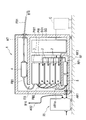
- FIG. 1 is an overall view for explaining a fiber laser processing apparatus according to an embodiment of the present invention.
- FIG. 2 is a diagram for explaining a fiber laser oscillator according to an embodiment of the present invention.
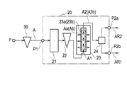
- FIG. 3 is a view for explaining an air purge unit of the fiber laser processing apparatus according to the embodiment of the present invention.
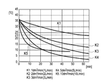
- FIG. 4 is a graph for explaining the dew point transition due to dehumidification of the fiber laser oscillator in one embodiment of the present invention.
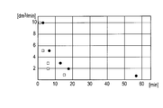
- FIG. 5 is another graph for explaining the dew point transition due to the dehumidifying operation of the fiber laser oscillator in one embodiment of the present invention.
- FIG. 1 is an overall view for explaining a fiber laser processing apparatus according to an embodiment of the present invention.
- FIG. 2 is a diagram for explaining a fiber laser oscillator according to an embodiment of the present invention.
- FIG. 3 is a view for explaining an air purge unit of the fiber laser processing apparatus according to the embodiment of the present invention.
- FIG. 4 is a graph for explaining
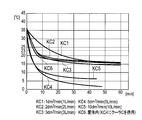
- FIG. 6 is a graph for explaining the dew point transition due to the dehumidifying operation of the fiber laser oscillator in Modification 1 of the embodiment of the present invention.
- FIG. 7 is a graph for explaining the dew point transition due to the dehumidifying operation of the fiber laser oscillator in the second modification of the embodiment of the present invention.
- a fiber laser oscillator 1 and a fiber laser processing apparatus 51 according to an embodiment of the present invention will be described with reference to FIGS.
- a fiber laser processing apparatus 51 includes a fiber laser processing machine 10 that performs laser processing on a workpiece W, and a fiber that supplies laser light to the fiber laser processing machine 10 via a process fiber FB1.
- a laser oscillator 1 and an air purge unit 20 for supplying dry air having a low dew point to the fiber laser oscillator 1 via the air supply path AR1 and to the fiber laser processing machine 10 via the air supply path AR2 are provided. .
- the fiber laser processing machine 10 includes a collimator unit 13 that collimates the laser light L emitted from the exit end face of the process fiber FB1 by the collimator lens 12, and a bend that reflects the laser light collimated by the collimator lens 12.
- the laser head 16 is configured so that dry air with a low dew point supplied from the air supply path AR2 can be introduced into the inside, thereby preventing dust from adhering to the optical system.
- the fiber laser oscillator 1 includes a housing KT, a light engine EG housed in a substantially sealed state inside the housing KT, a control unit SG for controlling the operation of the fiber laser oscillator 1, a power supply unit It has PW and cooling part RF.
- the control unit SG and the power supply unit PW also have a casing SG1 and a casing PW1, respectively, and the inside thereof is generally sealed.
- the light engine EG includes a plurality (four in this example) of fiber laser modules 2, a plurality of unit fibers FB2 for transmitting laser beams generated by the fiber laser modules 2, and a plurality of unit fibers FB2. And a combiner 3 that is welded together.
- a feed fiber FB3 and a beam switch 4 are connected in series between the combiner 3 and the process fiber FB1, and the laser light collectively output from the combiner 3 is fed to the feed fiber.
- the signal is output into the process fiber FB1 via the FB3 and the beam switch 4.
- the cooling unit RF includes a cooling water supply unit RF1 and a water channel system RF2 piped from the cooling water supply unit RF1 to each fiber laser module 2 and the power supply unit PW.
- the cooling water supply unit RF1 cools each fiber laser module 2 and the power supply unit PW by flowing cooling water through the water channel system RF2. Further, the cooling water supply unit RF1 maintains and manages the cooling water at 24 ° C., for example.
- a distributor 5 for distributing the low dew point dry air supplied from the air purge unit 20 via the air supply path AR1 to predetermined devices and parts is provided in the housing KT. Specifically, the low dew point dry air supplied to the distributor 5 is supplied to each of the plurality of fiber laser modules 2 via a plurality of air branches AR1a branched from the air supply path AR1.
- the fiber laser module 2 has a pumping light source using a semiconductor laser, a drive circuit, a heat sink, a resonator, and the like (all not shown) and is accommodated in the housing KT.
- the output of one fiber laser module 2 is about several hundred W (for example, 350 W). Therefore, since the four fiber laser modules 2 are provided in the example shown in FIG. 2, when the output of each fiber laser module 2 is 350 W, the laser light output from them is collected by the combiner 3. The light is emitted from the process fiber FB1 with an output of 1.4 kW.
- the air purge unit 20 includes an activated carbon tank 21, an oil mist filter 22, a low dew point reducing unit 23, and a branching unit 24.
- the air purge unit 20 has a supply port P1 on the input side and two delivery ports P2a and P2b on the output side.
- Compressed air A is supplied to the supply port P1.
- the supplied compressed air A passes through the activated carbon tank 21 and the oil mist filter 22 to remove oil, dust, oil mist, and the like, and then passes through the low dew point reduction unit 23.
- the dew point reduction unit 23 includes a nitrogen separation membrane module 23a that is a gas separation membrane module.
- the nitrogen separation membrane module 23a has a function of separating nitrogen (N 2 ) and argon (Ar) from other gas components using a speed difference that passes through the hollow fiber membrane.
- N 2 nitrogen
- Ar argon
- the nitrogen-rich and low dew point dry air A2 discharged from the low dew point reducing unit 23 is branched into two systems by the branching unit 24 and sent to the sending ports P2a and P2b, respectively.
- the dry air supplied to the delivery port P2a is delivered to the fiber laser processing machine 10 via the air supply path AR2.
- the dry air supplied to the delivery port P2b is sent to the distributor 5 of the fiber laser oscillator 1 via the air supply path AR1.
- the compressed air A supplied to the supply port P1 of the air purge unit 20 is generated by being compressed by the compressor on the air supply source P side, and passes through the prefilter 30 before being supplied to the air purge unit 20.
- the prefilter 30 removes relatively large foreign matters such as oil, foreign matter, oil mist, and water droplets mixed in the compressed air.
- a commercially available membrane separation type nitrogen gas generator using a nitrogen separation membrane module 23a can be used.
- a polyimide-based hollow fiber membrane is used for the nitrogen separation membrane module 23a.
- a membrane separation type nitrogen gas generator generates dry air having a low dew point of, for example, an atmospheric dew point of ⁇ 40 ° C. or lower (lower limit is ⁇ 60 ° C., for example) from air having a temperature of 40 ° C. and a humidity of 80% RT. Can do.
- Dehumidifying operation for supplying the low dew point dry air generated by the dew point reducing unit 23 using the membrane separation type nitrogen gas generator as described above into the fiber laser module 2 through the distributor 5 shown in FIG.
- the time course of the dew point temperature was measured for the air in the fiber laser module 2.
- the space volume inside the fiber laser module 2 was about 25 dm 3
- the ambient environment of the fiber laser module 2 was an air temperature of 40 ° C. and a humidity of 80% RH before the dehumidifying operation.
- the temperature of the cooling water supplied by the cooling unit RF was 24 ° C. ⁇ 1 ° C.
- the dew point reducing unit 23 one having the capability of generating dry air having a low dew point of ⁇ 40 ° C. at an atmospheric pressure dew point from air having a temperature of 40 ° C. and a humidity of 80% RH was used.
- the time t (hereinafter also referred to as dehumidification time t) from the start of supply of the low dew point dry air generated from the compressed air A1 until the dew point temperature becomes less than 23 ° C. is supplied per minute of the low dew point dry air.
- Transition K1 (1 dm 3 / min): 57 minutes 30 seconds (3450 seconds)
- Transition K2 (2 dm 3 / min): 17 minutes 40 seconds (1060 seconds)
- Transition K3 3 dm 3 / min): 12 minutes 46 seconds (766 seconds)
- Transition K4 5 dm 3 / min): 6 minutes 05 seconds (365 seconds)
- Transition K5 10 dm 3 / min: 2 minutes 35 seconds (155 seconds)
- the supply amount in the transition K1 is a conventional level using a small pump that does not use compressed air for purging. Compared with this transition K1 and the transition K5 using compressed air supplied as purge air, when using compressed air, the dehumidification time t in the fiber laser oscillator 1 is reduced from 3450 seconds to 155 seconds, That is, it is shortened to about 4.5% (about 1/22).
- the fiber laser oscillator 1 Since the dehumidifying time t is, for example, the time from when the user turns on the power until the laser beam is output, the fiber laser oscillator 1 has a very short waiting time until the operation becomes possible and is very convenient to use. It has become.
- the low dew point dry air is directly fed into the fiber laser module 2 and the power supply unit PW. Since it is supplied, the dew point temperature of the air inside each does not rise rapidly.
- the fiber laser processing apparatus 51 has conventionally used, for example, a membrane using a nitrogen separation membrane module as a gas separation membrane module after removing foreign matter using a filter from purged compressed air that is installed in a factory and supplied to a processing machine or the like. Dehumidify through a separate nitrogen gas generator. Then, the low dew point dry air obtained by dehumidification is branched into a plurality of supply paths, and the low dew point dry air is supplied to the fiber laser oscillator 1 through one of the branched supply paths. It supplies to the fiber laser processing machine 10 through a supply path.
- the low dew point dry air supplied to the fiber laser oscillator 1 is supplied to each of the plurality of fiber laser modules by the distributor 5 so that the inside of the fiber laser module 2 is dehumidified to reduce the dew point of the air inside. It has become.
- a large flow rate of low dew point dry air can be supplied to the inside of the fiber laser module 2, and the waiting time from the start of the dehumidification operation to the output of laser light is short, making the fiber laser processing apparatus easy to use. Can be very good.
- a low dew point dry air supply path is provided with a valve that adjusts the supply amount of low dew point dry air per unit time so that power is saved in the range where dew point temperature does not rise and condensation occurs.
- the degree of opening may be adjusted by the control unit SG.
- a flow switch may be provided in the low dew point dry air supply path to monitor the flow rate, and an abnormality may be notified by an alarm or the like when the flow rate falls below a predetermined value.
- FIG. 6 shows the condition of the air in the fiber laser module 2 when the dehumidification of the air in the housing KT by the cooler C is simultaneously performed in addition to the dehumidification only of the low dew point dry air supply shown in FIG. It is the graph which showed the time change of dew point temperature.
- the dehumidifying time t for each of the transitions KC1 to 5 in this case is Transition KC1 (1 dm 3 / min): 15 minutes 10 seconds (910 seconds), Transition KC2 (2 dm 3 / min): 5 minutes 50 seconds (350 seconds), Transition KC3 ( 3 dm 3 / min): 5 minutes 55 seconds (355 seconds), Transition KC4 (5 dm 3 / min): 2 minutes 5 seconds (125 seconds)), Transition KC5 (10 dm 3 / min): 1 minute 45 seconds (105 seconds), It has become.
- transition KC6 the transition of the dew point temperature of the air inside the housing KT and outside the fiber laser module 2 and the power supply unit PW is measured, and is shown as transition KC6 in FIG.
- the dehumidification time t that is, the dehumidification time of the air in the housing KT
- t in the transition KC6 is the transition KC6 (in the housing): 6 minutes 3 seconds (183 seconds).
- the air in the housing KT is also dehumidified in parallel, so that the dehumidifying time t can be shortened to about half, and the fiber laser oscillator This is preferable because the waiting time until the first operation becomes possible is further shortened and the usability is improved.
- a membrane air dryer may be used instead of the membrane separation type nitrogen gas generator.
- the membrane-type air dryer uses a moisture-permeable membrane module 23b (see FIG. 3) in which a hollow fiber membrane such as a porous fluorine-based material having moisture permeability is bundled as a gas separation membrane module, and uses the supplied compressed air.
- the dry air is generated by dehumidification by the moisture permeable membrane module 23b.
- FIG. 7 shows the results of measuring the time change of the dew point temperature of the air in the fiber laser module 2 by performing a dehumidifying operation using a membrane air dryer provided with a moisture permeable membrane module 23b which is a gas separation membrane module. This time variation of the dew point temperature is shown as transition KC7 in FIG.
- the supply amount of dry air is 5 dm 3 / min, and in this dehumidification operation, dehumidification in the casing KT by the cooler C is simultaneously performed in parallel. Accordingly, the conditions other than the use of the membrane air dryer are the same in the dehumidifying operation, and the transition KC7 is transition data that can be compared with the transition KC4 shown in FIG. Therefore, in FIG. 7, the transition KC4 is also shown for easy understanding.
- the dehumidifying time t7 until the dew point temperature became less than 23 ° C. in the transition KC7 was 1 minute 53 seconds (113 seconds). This is a result evaluated to be almost equivalent to 2 minutes 5 seconds (125 seconds) in the transition KC4.
- the membrane air dryer using the moisture permeable membrane module 23b has sufficient dehumidifying performance, and the nitrogen separation membrane module 23a. It was confirmed that the same effect as when using was exhibited.
- the membrane air dryer Since the membrane air dryer is small and light and easy to install, it is suitable for incorporation into equipment such as the air purge unit 20. Moreover, since a power supply is unnecessary, handling is easy. Needless to say, in the dehumidifying operation using this membrane-type air dryer, the dehumidification in the casing KT by the cooler C may not be performed in parallel.
- the fiber laser beam machine 10 may be supplied with compressed air branched on the upstream side of the air purge unit 20.
- compressed air branched on the upstream side of the air purge unit 20 since the low dew point dry air that has passed through the air purge unit 20 is clean air from which oil mist, relatively coarse dust, and the like have been removed, air that is branched downstream of the air purge unit 20 as described above is supplied. It is preferable. Further, even when compressed air branched on the upstream side of the air purge unit 20 is supplied, oil mist, dust and the like are removed from the supplied compressed air so as not to impair the optical functions of the optical components. There is a need.
- the laser processing machine may be welded or other than the one that cuts the workpiece W, and the type of processing is not limited.
- the air purge unit 20 may be integrally accommodated in the fiber laser oscillator 1.
- the upstream side of the air supply path AR ⁇ b> 2 whose downstream side is connected to the fiber laser processing machine 10 is connected to the fiber laser oscillator 1.
Landscapes
- Physics & Mathematics (AREA)
- Electromagnetism (AREA)
- Engineering & Computer Science (AREA)
- Plasma & Fusion (AREA)
- Optics & Photonics (AREA)
- Microelectronics & Electronic Packaging (AREA)
- Laser Beam Processing (AREA)
- Separation Using Semi-Permeable Membranes (AREA)
- Lasers (AREA)
- Optical Couplings Of Light Guides (AREA)
Description
本発明は、ファイバレーザ発振器、ファイバレーザ加工装置、及びファイバレーザ発振器の除湿方法に係る。
ファイバレーザ発振器は、筐体と、その筐体内に概ね密閉状態で収容された光エンジン、発振動作を制御する制御装置、及び冷却装置と、を有して構成されている。光エンジンは、レーザ光源としての半導体レーザを有する複数のファイバレーザモジュールと、各ファイバレーザモジュールで生成されたレーザ光を結合するコンバイナと、を備えている。コンバイナで結合されたレーザ光は、プロセスファイバを介して外部へ出力される。
一般的に、半導体レーザのレーザ発振効率には温度依存性がある。そのため、レーザ光の発振に伴い発熱する光エンジンの温度を冷却により適温で維持し、常に高い発振効率が得られるようにしておく必要がある。冷却装置はその光エンジンの適温維持のために備えられている。この冷却は、通常、筐体内に配設された冷却水路(冷却パイプ)内に、例えば24℃の冷却水を流入循環させることで行う。
ところで、筐体内の空気に含まれる水蒸気の量が、冷却水の温度(例えば24℃)における飽和水蒸気量を超えていると、冷却パイプの表面に結露が発生し、光エンジン内の電子部品等に不具合が生じる可能性が高くなる。そのため、冷却水の冷却パイプ内への注入は、筐体内の空気やファイバレーザモジュール内の空気の湿度を、除湿装置により充分に低くしてから行う必要がある。
特許文献1には、このような除湿装置を筐体内に備えたファイバレーザ発振器として、筐体内に複数のLDモジュールそれぞれに乾燥させた空気(低露点のドライエア)を供給するための除湿装置を備えたファイバレーザ発振器が提案されている。具体的には、除湿により得られた低露点のドライエアを、小型のポンプで毎分1L(1dm3)程度供給する実施例が提案されている一方、従来からレーザ加工機等に設置されていたパージ用エアを供給する装置を使用する旨が記載されている。
特許文献1に記載の装置において、低露点のドライエアの供給に小型のポンプを用いた場合には毎分1dm3程度の空気が供給される。
しかしながら、その供給可能な低露点のドライエアの流量にはおのずと限界があり、筐体内の空気の温度及び湿度の関係によっては、例えば、電源投入等により除湿を開始してから除湿が充分になされてファイバレーザの出力が可能になるまで比較的長い時間を要する場合があった。
一方で、市場からはファイバレーザ加工装置に対して大出力化が要望されており、その要望に応えるべく、ファイバレーザ発振器の大出力化が進められている。そして、この大出力化を余力を持って可能にするための冷却システムや除湿システムの高能力化も将来的に予想される。
このような状況において、外部からパージ用エアとして豊富に供給され得る圧縮空気の利用は有効であると考えられるが、その圧縮空気を除湿に利用する場合の具体的な構成等について特許文献1では提案されていない。
そこで、本発明が解決しようとする課題は、パージ用エアを用い、除湿により除湿開始から加工動作が可能となるまでの待ち時間が短く使い勝手が良いファイバレーザ発振器、ファイバレーザ加工装置及びファイバレーザ発振器の除湿方法を提供することにある。
上記の課題を解決するために、レーザ光を出力する複数のファイバレーザモジュールと、前記複数のファイバレーザモジュールのそれぞれから出力されたレーザ光をコンバインして外部に送出するコンバイナと、外部から供給されるパージ用の圧縮空気を気体分離膜モジュールにより低露点のドライエアにする低露点化部と、前記ドライエアを前記複数のファイバレーザモジュールのそれぞれに分配供給するディストリビュータと、を備えたことを特徴とするファイバレーザ発振器が提供される。
また、外部から供給されるパージ用の圧縮空気を気体分離膜モジュールにより低露点のドライエアにする低露点化部を有するエアパージユニットと、レーザ光を出力する複数のファイバレーザモジュールと、前記複数のファイバレーザモジュールのそれぞれから出力されたレーザ光をコンバインして外部に送出するコンバイナと、前記ドライエアを前記複数のファイバレーザモジュールのそれぞれに分配供給するディストリビュータと、を有するファイバレーザ発振器と、前記コンバイナから送出されたレーザ光によりワークに対してレーザ加工を施すレーザ加工機と、を備えたファイバレーザ加工装置が提供される。
さらに、レーザ光を出力する複数のファイバレーザモジュールと、前記複数のファイバレーザモジュールのそれぞれから出力されたレーザ光をコンバインして外部に送出するコンバイナと、を備えたファイバレーザ発振器の除湿方法であって、外部から供給されたパージ用の圧縮空気を気体分離膜モジュールにより除湿して低露点のドライエアとするドライエア生成ステップと、前記ドライエアを前記複数のファイバレーザモジュールのそれぞれに分配供給するドライエア供給ステップと、を含むことを特徴とするファイバレーザ発振器の除湿方法が提供される。
本発明の一実施形態であるファイバレーザ発振器1及びファイバレーザ加工装置51を図1~図6を用いて説明する。
まず、ファイバレーザ加工装置51について図1を参照して説明する。図1に示されるように、ファイバレーザ加工装置51は、ワークWに対してレーザ加工を行うファイバレーザ加工機10と、ファイバレーザ加工機10に対しレーザ光をプロセスファイバFB1を介して供給するファイバレーザ発振器1と、低露点のドライエアを、エア供給路AR1を介してファイバレーザ発振器1に供給すると共にエア供給路AR2を介してファイバレーザ加工機10に供給するエアパージユニット20と、を備えている。
ファイバレーザ加工機10は、プロセスファイバFB1の出口端面から拡がって出射したレーザ光Lをコリメータレンズ12で平行光にするコリメータユニット13と、コリメータレンズ12により平行光にされたレーザ光を反射するベンドミラー14と、ベンドミラー14で反射したレーザ光を集光レンズ15で高エネルギー密度のレーザ光に集光するレーザヘッド16と、集光したレーザ光により加工を施すワークWが設置される加工テーブル18とを備えている。また、レーザヘッド16は、エア供給路AR2から供給された低露点のドライエアを内部に導入可能なものとして光学系への塵埃の付着を防止するようになっている。
次に、ファイバレーザ発振器1について図2を主に参照して説明する。図2において、ファイバレーザ発振器1は、筐体KTと、筐体KTの内部に概ね密閉状態で収容された光エンジンEGと、このファイバレーザ発振器1の動作を制御する制御部SGと、電源部PWと、冷却部RFと、を有している。制御部SG及び電源部PWについても、それぞれ筐体SG1及び筐体PW1を有し、その内部は概ね密閉状態とされている。
光エンジンEGは、複数(この例では四つ)のファイバレーザモジュール2と、各ファイバレーザモジュール2で生成されたレーザ光をそれぞれ伝送する複数のユニットファイバFB2と、複数のユニットファイバFB2を1つに融接して纏めるコンバイナ3と、を有している。コンバイナ3とプロセスファイバFB1との間には、フィードファイバFB3及びビームスイッチ4とが直列的に接続されて設けられており、コンバイナ3から一つに纏められて出力されたレーザ光は、フィードファイバFB3及びビームスイッチ4を経てプロセスファイバFB1内へ出力されるようになっている。
冷却部RFは、冷却水供給部RF1と、その冷却水供給部RF1から各ファイバレーザモジュール2及び電源部PWの内部を巡るようにそれぞれに配管された水路系RF2と、を有する。冷却水供給部RF1は、水路系RF2内に冷却水を流して各ファイバレーザモジュール2及び電源部PWの冷却を行う。また、冷却水供給部RF1は、冷却水を例えば24℃で維持管理する。
さらに、筐体KT内には、エアパージユニット20からエア供給路AR1を介して供給された低露点のドライエアを所定の機器や部位へ分配するディストリビュータ5が設けられている。具体的には、ディストリビュータ5へ供給された低露点のドライエアは、複数のファイバレーザモジュール2それぞれに対し、エア供給路AR1から分岐させた複数のエア支路AR1aを介して供給される。
ファイバレーザモジュール2は、半導体レーザによる励起光源、駆動回路、ヒートシンク、及び共振器等(いずれも図示せず)を有して筐体KT内に収容されている。一つのファイバレーザモジュール2の出力は約数百W(例えば350W)である。従って、図2に示された例では四つのファイバレーザモジュール2を備えているので、各ファイバレーザモジュール2の出力が350Wの場合、それらから出力されたレーザ光は、コンバイナ3で纏められた後、プロセスファイバFB1から1.4kWの出力で出射される。
次に、エアパージユニット20について図3を主に参照して説明する。エアパージユニット20は、活性炭槽21とオイルミストフィルタ22と低露点化部23と分岐部24とを有している。また、エアパージユニット20は入力側として供給ポートP1を、また、出力側として二つの送出ポートP2a,P2bを有している。
供給ポートP1には、圧縮空気Aが供給される。供給された圧縮空気Aは、活性炭槽21及びオイルミストフィルタ22を通過して、油分、粉塵、オイルミスト等が除去され、その後、低露点化部23を通過する。
低露点化部23は、気体分離膜モジュールである窒素分離膜モジュール23aを有している。窒素分離膜モジュール23aは、窒素(N2)やアルゴン(Ar)を、中空糸膜を透過する速度差を利用して他のガス成分から分離する機能を有する。形状としては、中空糸膜を束ねた筒状とされており、筒状の一端側が空気の入口とされ、他端側が中空糸膜の性質を利用して処理された空気の出口とされている。
窒素分離膜モジュール23aの一端側から内部に、オイルミストフィルタ22を通過した圧縮空気A1を供給すると、窒素(N2)やアルゴン(Ar)よりも中空糸膜を通過し易い酸素(02)、水蒸気(H2O)、及び二酸化炭素(CO2)などが筒状壁から外部へ抜け出し(矢印Aa参照)、酸素及び水蒸気濃度が低下した窒素リッチかつ低露点のドライエアA2となって他端側から排出される。
低露点化部23から排出された窒素リッチかつ低露点のドライエアA2は、分岐部24により2系統に分岐され、それぞれ送出ポートP2a,P2bに送出される。送出ポートP2aに供給されたドライエアは、エア供給路AR2を介してファイバレーザ加工機10に向け送出される。送出ポートP2bに供給されたドライエアは、エア供給路AR1を介してファイバレーザ発振器1のディストリビュータ5に向け送出される。
エアパージユニット20の供給ポートP1に供給される圧縮空気Aは、エア供給源P側のコンプレッサで圧縮されて生成され、エアパージユニット20に供給される前にプレフィルタ30を通過するようになっている。プレフィルタ30では、圧縮空気に混合した比較的大きな、油分、異物、オイルミスト、及び水滴などの異物が除去される。
低露点化部23として、窒素分離膜モジュール23aを用いた市販の膜分離型窒素ガス発生装置を用いることができる。窒素分離膜モジュール23aには、例えばポリイミド系の中空糸膜が用いられる。一般的に、膜分離型窒素ガス発生装置は、例えば温度40℃、湿度80%RTの空気から大気圧露点で-40℃以下(下限は例えば-60℃)の低露点のドライエアを生成することができる。
上述のような膜分離型窒素ガス発生装置を用いた低露点化部23で生成された低露点のドライエアを、図2に示されるディストリビュータ5を介してファイバレーザモジュール2の内部に供給する除湿作業を行い、ファイバレーザモジュール2内の空気について、露点温度の時間推移が測定された。
ここで、ファイバレーザモジュール2の内部の空間容積は、約25dm3であり、ファイバレーザモジュール2の周囲環境は、除湿作業前において気温40℃、湿度80%RHであった。また、冷却部RFが供給する冷却水の温度は24℃±1℃であった。また、低露点化部23としては、気温40℃、湿度80%RHの空気から大気圧露点で-40℃の低露点のドライエアを生成する能力のものを用いた。
これらの条件の下、この測定では、低露点のドライエアの供給量を、従来の1dm3/minから、エアパージユニット20で充分供給可能な10dm3/minまで、5段階で測定した。その結果を図4のグラフに示す。
図4において、露点温度が冷却水の下限温度である23℃未満となれば、ファイバレーザモジュール2内の空気中の水蒸気量が飽和水蒸気量を上回ることはなく、結露が生じない。
そこで、圧縮空気A1から生成された低露点のドライエアの供給開始から露点温度が23℃未満となるまでの時間t(以下、除湿時間tとも称する)を、低露点のドライエアの毎分当たりの供給量が異なる推移K1~K5それぞれについて評価した。
その結果、各推移における除湿時間tとして、
推移K1(1dm3/min):57分30秒(3450秒)、
推移K2(2dm3/min):17分40秒(1060秒)、
推移K3(3dm3/min):12分46秒(766秒)、
推移K4(5dm3/min):6分05秒(365秒)、
推移K5(10dm3/min):2分35秒(155秒)、
が得られた。この結果は図5のグラフにおいて黒丸のプロットで示されている。
推移K1(1dm3/min):57分30秒(3450秒)、
推移K2(2dm3/min):17分40秒(1060秒)、
推移K3(3dm3/min):12分46秒(766秒)、
推移K4(5dm3/min):6分05秒(365秒)、
推移K5(10dm3/min):2分35秒(155秒)、
が得られた。この結果は図5のグラフにおいて黒丸のプロットで示されている。
推移K1における供給量は、パージ用の圧縮空気を利用していない小型ポンプを用いた従来のレベルである。この推移K1とパージ用のエアとして供給された圧縮空気を利用した推移K5の場合と比較すると、圧縮空気を利用した場合、ファイバレーザ発振器1における除湿時間tは、3450秒から155秒に短縮、すなわち約4.5%(約1/22)に短縮している。
除湿時間tは、例えばユーザが電源を投入してからレーザ光が出力されるまでの時間であるので、ファイバレーザ発振器1は、動作が可能になるまでの待ち時間が大変短く使い勝手が極めて良いものとなっている。
上述した構成によれば、ファイバレーザ発振器1のメンテナンスのために、筐体KTの扉(図示せず)を開けた場合でも、低露点のドライエアはファイバレーザモジュール2及び電源部PWの内部に直接供給されるので、各内部の空気の露点温度が急激に上昇することはない。
ファイバレーザ加工装置51は、従来、工場内に設備され加工機等に供給されているパージ用の圧縮空気を、フィルタによる異物除去をした後に気体分離膜モジュールとして窒素分離膜モジュールを用いた例えば膜分離型窒素ガス発生装置に通して除湿する。そして、除湿して得られた低露点のドライエアを複数の供給路に分岐し、分岐した内の一供給路を介して低露点のドライエアをファイバレーザ発振器1に供給し、分岐した内の他の供給路を介してファイバレーザ加工機10に供給する。そして、ファイバレーザ発振器1に供給された低露点のドライエアをディストリビュータ5により複数のファイバレーザモジュールそれぞれに供給することで、ファイバレーザモジュール2内を除湿してその内部の空気の低露点化を行うようになっている。
この除湿方法によれば、ファイバレーザモジュール2の内部に大流量の低露点のドライエアを供給でき、除湿動作開始からレーザ光の出力が可能となるまでの待ち時間が短くファイバレーザ加工装置の使い勝手を極めて良好にすることができる。
上述した除湿動作は制御部SGによって制御される。例えば、低露点のドライエアの供給経路に、単位時間あたりの低露点のドライエアの供給量を、露点温度が上昇して結露を生じない範囲で省電力となるように調節するバルブを設け、そのバルブの開度を制御部SGにより調節するようにしてもよい。また、低露点のドライエアの供給経路にフロースイッチを設けて流量を監視し、流量が所定値を下回ったときにアラーム等で異常を告知するようにしてもよい。
本発明の実施形態は、上述した構成に限定されるものではなく、本発明の要旨を逸脱しない範囲において変形例としてもよいのは言うまでもない。
(変形例1)
除湿動作については、上述したファイバレーザモジュール2及び電源部PWに対する低露点のドライエアの供給による除湿動作と並行して、クーラCによる筐体KT内の空気の除湿動作を行ってもよい。この場合、クーラCは、例えば、図1及び図2に破線で示されるように筐体KTに併設する。これらの除湿動作は制御部SGによって制御される。
除湿動作については、上述したファイバレーザモジュール2及び電源部PWに対する低露点のドライエアの供給による除湿動作と並行して、クーラCによる筐体KT内の空気の除湿動作を行ってもよい。この場合、クーラCは、例えば、図1及び図2に破線で示されるように筐体KTに併設する。これらの除湿動作は制御部SGによって制御される。
図6は、図4で示した低露点のドライエアの供給のみの除湿に加えて、クーラCによる筐体KT内空気の除湿を並行して同時に行った場合の、ファイバレーザモジュール2内の空気の露点温度の時間変化を示したグラフである。
この場合の推移KC1~5それぞれについての除湿時間tは、
推移KC1(1dm3/min):15分10秒(910秒)、
推移KC2(2dm3/min):5分50秒(350秒)、
推移KC3(3dm3/min):5分55秒(355秒)、
推移KC4(5dm3/min):2分5秒(125秒))、
推移KC5(10dm3/min):1分45秒(105秒)、
となっている。これらの結果は図5のグラフに白ヌキの角プロットで示されている。
推移KC1(1dm3/min):15分10秒(910秒)、
推移KC2(2dm3/min):5分50秒(350秒)、
推移KC3(3dm3/min):5分55秒(355秒)、
推移KC4(5dm3/min):2分5秒(125秒))、
推移KC5(10dm3/min):1分45秒(105秒)、
となっている。これらの結果は図5のグラフに白ヌキの角プロットで示されている。
さらに、推移KC3の試験では、筐体KTの内部であってファイバレーザモジュール2及び電源部PWの外側の空気の露点温度の推移を測定しており、図6において推移KC6として示している。推移KC6における除湿時間t(すなわち、筐体KT内の空気の除湿時間)tは、推移KC6(筐体内):6分3秒(183秒)である。
図6から明らかなように、ファイバレーザモジュール2及び電源部PWの除湿動作において、並行して筐体KT内の空気も除湿することは、除湿時間tが約半分程度に短縮でき、ファイバレーザ発振器1の動作が可能になるまでの待ち時間が更に短く使い勝手がより良くなるので好ましい。
(変形例2)
ファイバレーザ装置51におけるエアパージユニット20の低露点化部23として、膜分離型窒素ガス発生装置ではなく、膜式エアドライヤを用いてもよい。膜式エアドライヤは、気体分離膜モジュールとして、透湿性を有する多孔質フッ素系等の中空糸膜を束ねて筒状とした透湿膜モジュール23b(図3参照)を用い、供給された圧縮空気を透湿膜モジュール23bにより除湿してドライエアを生成するものである。
ファイバレーザ装置51におけるエアパージユニット20の低露点化部23として、膜分離型窒素ガス発生装置ではなく、膜式エアドライヤを用いてもよい。膜式エアドライヤは、気体分離膜モジュールとして、透湿性を有する多孔質フッ素系等の中空糸膜を束ねて筒状とした透湿膜モジュール23b(図3参照)を用い、供給された圧縮空気を透湿膜モジュール23bにより除湿してドライエアを生成するものである。
図3を参照して具体的に説明すると、透湿膜モジュール23bの一端側から内部にオイルミストフィルタ22を通過した圧縮空気A1を供給すると、膜の内外での水蒸気分圧差によって圧縮空気A1中の水蒸気(H2O)が膜に浸透して筒状壁から外部へ抜け出し(矢印Ab参照)、水分のみが取り除かれたドライエアA2bとなって他端側から排出される。この排出されたドライエアA2bは、ファイバレーザ発振器1のディストリビュータ5に向け送出される。
気体分離膜モジュールである透湿膜モジュール23bを備えた膜式エアドライヤを用いて除湿動作を行い、ファイバレーザモジュール2内の空気の露点温度の時間変化を測定した結果を図7に示す。この露点温度の時間変化は、図7において推移KC7として示されている。
ここで、ドライエアの供給量は5dm3/minであり、この除湿動作ではクーラCによる筐体KT内の除湿を並行して同時に行っている。従って、除湿動作において、膜式エアドライヤを用いたこと以外の条件は同じであり、推移KC7は、図6に示された推移KC4と対比可能な推移データである。そこで、図7では理解容易のために推移KC4を併記してある。
図7に示されるように、推移KC7において露点温度が23℃未満になるまでの除湿時間t7は、1分53秒(113秒)であった。これは、推移KC4における2分5秒(125秒)とほぼ同等と評価される結果であり、透湿膜モジュール23bを用いた膜式エアドライヤは充分な除湿性能があって、窒素分離膜モジュール23aを用いた場合と同様の効果が発揮されることが確認された。
膜式エアドライヤは、小型軽量であり取り付けが容易なので、エアパージユニット20等の機器への組み込みに好適である。また、電源が不要なので、取り扱いが容易である。この膜式エアドライヤを用いた除湿動作において、クーラCによる筐体KT内の除湿を並行して行わなくてもよいことは言うまでもない。
(他の変形例)
ファイバレーザ加工機10へは、エアパージユニット20の上流側で分岐された圧縮空気を供給してもよい。ただ、エアパージユニット20を経た低露点のドライエアは、オイルミストや比較的粗い粉塵等が除去された清浄なエアであるので、上述したようなエアパージユニット20の下流側で分岐されたエアを供給することは好ましい。また、エアパージユニット20の上流側で分岐された圧縮空気を供給する場合であっても、光学部品の光学的機能を損なわないように、供給する圧縮空気からオイルミストや粉塵等は除去しておく必要がある。
ファイバレーザ加工機10へは、エアパージユニット20の上流側で分岐された圧縮空気を供給してもよい。ただ、エアパージユニット20を経た低露点のドライエアは、オイルミストや比較的粗い粉塵等が除去された清浄なエアであるので、上述したようなエアパージユニット20の下流側で分岐されたエアを供給することは好ましい。また、エアパージユニット20の上流側で分岐された圧縮空気を供給する場合であっても、光学部品の光学的機能を損なわないように、供給する圧縮空気からオイルミストや粉塵等は除去しておく必要がある。
なお、レーザ加工機は、ワークWを切断するもの以外に溶接するもの或いはその他のものでもよく、加工の種類は限定されない。
また、ファイバレーザ発振器1の内部に、エアパージユニット20を一体的に収容してもよい。この場合、下流側がファイバレーザ加工機10に接続されたエア供給路AR2の上流側は、ファイバレーザ発振器1に接続される。
以上の説明から明らかなように、本発明によれば、除湿により除湿開始から加工動作が可能となるまでの待ち時間が短く使い勝手が良いという効果が得られる。
Claims (9)
- レーザ光を出力する複数のファイバレーザモジュールと、
前記複数のファイバレーザモジュールのそれぞれから出力されたレーザ光をコンバインして外部に送出するコンバイナと、
外部から供給されるパージ用の圧縮空気を気体分離膜モジュールにより低露点のドライエアにする低露点化部と、
前記ドライエアを前記複数のファイバレーザモジュールのそれぞれに分配供給するディストリビュータと、
を備えたことを特徴とするファイバレーザ発振器。 - 前記複数のファイバレーザモジュールを収容する筐体と、
前記筐体の内部の空間を除湿するクーラと、
をさらに備えていることを特徴とする請求項1記載のファイバレーザ発振器。 - 前記ドライエアは、大気圧露点が-40℃以下であることを特徴とする請求項1又は請求項2記載のファイバレーザ発振器。
- 外部から供給されるパージ用の圧縮空気を気体分離膜モジュールにより低露点のドライエアにする低露点化部を有するエアパージユニットと、
レーザ光を出力する複数のファイバレーザモジュールと、前記複数のファイバレーザモジュールのそれぞれから出力されたレーザ光をコンバインして外部に送出するコンバイナと、前記ドライエアを前記複数のファイバレーザモジュールのそれぞれに分配供給するディストリビュータと、を有するファイバレーザ発振器と、
前記コンバイナから送出されたレーザ光によりワークに対してレーザ加工を施すレーザ加工機と、
を備えたファイバレーザ加工装置。 - 前記複数のファイバレーザモジュールを収容する筐体と、
前記筐体の内部の空間を除湿するクーラと、
をさらに備えていることを特徴とする請求項4記載のファイバレーザ加工装置。 - 前記ドライエアは、大気圧露点が-40℃以下であることを特徴とする請求項4又は請求項5記載のファイバレーザ加工装置。
- レーザ光を出力する複数のファイバレーザモジュールと、前記複数のファイバレーザモジュールのそれぞれから出力されたレーザ光をコンバインして外部に送出するコンバイナと、を備えたファイバレーザ発振器の除湿方法であって、
外部から供給されたパージ用の圧縮空気を気体分離膜モジュールにより除湿して低露点のドライエアとするドライエア生成ステップと、
前記ドライエアを前記複数のファイバレーザモジュールのそれぞれに分配供給するドライエア供給ステップと、
を含むことを特徴とするファイバレーザ発振器の除湿方法。 - 前記ファイバレーザ発振器は、前記複数のファイバレーザモジュールを収容する筐体と、前記筐体の内部の空間を除湿するクーラと、をさらに備え、
前記クーラにより前記筐体の内部の空間を除湿する除湿ステップを、前記ドライエア供給ステップと並行して実行することを特徴とする請求項7記載のファイバレーザ発振器の除湿方法。 - 前記ドライエアは、大気圧露点が-40℃以下であることを特徴とする請求項7又は請求項8記載のファイバレーザ発振器の除湿方法。
Priority Applications (3)
| Application Number | Priority Date | Filing Date | Title |
|---|---|---|---|
| CN201380019753.0A CN104221231B (zh) | 2012-04-16 | 2013-04-05 | 光纤激光振荡器、光纤激光加工装置以及光纤激光振荡器的除湿方法 |
| EP13779047.3A EP2840670B1 (en) | 2012-04-16 | 2013-04-05 | Fiber laser oscillator, fiber laser processing device, and fiber laser oscillator dehumidification method |
| US14/391,062 US9548583B2 (en) | 2012-04-16 | 2013-04-05 | Fiber laser oscillator, fiber laser processing device, and fiber laser oscillator dehumidification method |
Applications Claiming Priority (4)
| Application Number | Priority Date | Filing Date | Title |
|---|---|---|---|
| JP2012-092609 | 2012-04-16 | ||
| JP2012092609 | 2012-04-16 | ||
| JP2012-280816 | 2012-12-25 | ||
| JP2012280816A JP2013239696A (ja) | 2012-04-16 | 2012-12-25 | ファイバレーザ発振器,ファイバレーザ加工装置,及びファイバレーザ発振器の除湿方法 |
Publications (1)
| Publication Number | Publication Date |
|---|---|
| WO2013157414A1 true WO2013157414A1 (ja) | 2013-10-24 |
Family
ID=49383378
Family Applications (1)
| Application Number | Title | Priority Date | Filing Date |
|---|---|---|---|
| PCT/JP2013/060477 Ceased WO2013157414A1 (ja) | 2012-04-16 | 2013-04-05 | ファイバレーザ発振器、ファイバレーザ加工装置、及びファイバレーザ発振器の除湿方法 |
Country Status (5)
| Country | Link |
|---|---|
| US (1) | US9548583B2 (ja) |
| EP (1) | EP2840670B1 (ja) |
| JP (1) | JP2013239696A (ja) |
| CN (1) | CN104221231B (ja) |
| WO (1) | WO2013157414A1 (ja) |
Families Citing this family (23)
| Publication number | Priority date | Publication date | Assignee | Title |
|---|---|---|---|---|
| GB0816310D0 (en) | 2008-09-05 | 2008-10-15 | Mtt Technologies Ltd | Filter assembly |
| JP6252423B2 (ja) * | 2014-09-30 | 2017-12-27 | ブラザー工業株式会社 | レーザ加工ヘッド |
| JP6503175B2 (ja) * | 2014-10-14 | 2019-04-17 | 株式会社アマダホールディングス | 半導体レーザ発振器及びレーザ加工機 |
| JP6435153B2 (ja) * | 2014-10-14 | 2018-12-05 | 株式会社アマダホールディングス | レーザ共振器、レーザ加工装置及びレーザ共振器の除湿方法 |
| JP2017538038A (ja) * | 2014-11-21 | 2017-12-21 | レニショウ パブリック リミテッド カンパニーRenishaw Public Limited Company | 付加製造装置および方法 |
| JP2016198793A (ja) * | 2015-04-09 | 2016-12-01 | ファナック株式会社 | 発光部及び制御装置を一体的に移動可能にしたレーザ加工システム |
| JP6235527B2 (ja) * | 2015-05-14 | 2017-11-22 | ファナック株式会社 | 結露の発生を予測する機能を備えたレーザ装置 |
| JP6267164B2 (ja) * | 2015-08-24 | 2018-01-24 | ファナック株式会社 | 保守作業用の温度管理機能を有するレーザ装置 |
| JP6285404B2 (ja) | 2015-12-04 | 2018-02-28 | ファナック株式会社 | 結露防止機能を有するレーザ装置 |
| WO2017163762A1 (ja) * | 2016-03-23 | 2017-09-28 | パナソニックIpマネジメント株式会社 | ファイバ空間結合装置 |
| CN107749555A (zh) * | 2017-11-20 | 2018-03-02 | 苏州紫光伟业激光科技有限公司 | 一种多功能的激光器的散热除湿装置 |
| WO2020004288A1 (ja) * | 2018-06-29 | 2020-01-02 | パナソニックIpマネジメント株式会社 | レーザ装置及びレーザ装置の除湿管理方法 |
| CN109557873B (zh) * | 2018-12-10 | 2020-10-20 | 雷斯罗普(北京)激光科技有限公司 | 一种激光清洗机控制系统 |
| JP7088861B2 (ja) * | 2019-02-12 | 2022-06-21 | ファナック株式会社 | 除湿機能を高めたレーザ発振器 |
| CN109713557B (zh) * | 2019-03-14 | 2024-04-30 | 苏州创鑫激光科技有限公司 | 高功率多模块激光器及其光电模组 |
| JP7419670B2 (ja) * | 2019-05-23 | 2024-01-23 | 住友電気工業株式会社 | 光ファイバの製造方法、および光ファイバの製造装置 |
| JP7257295B2 (ja) * | 2019-09-06 | 2023-04-13 | 株式会社アマダ | ファイバレーザ発振器及びファイバレーザ発振器のメンテナンスシステム |
| JP7279600B2 (ja) * | 2019-09-26 | 2023-05-23 | ブラザー工業株式会社 | レーザ加工装置 |
| CN110899987B (zh) * | 2019-11-26 | 2021-12-10 | 中沃(泰州)激光科技有限公司 | 一种使用便捷的环保型激光打标机 |
| JP2021093398A (ja) * | 2019-12-06 | 2021-06-17 | ファナック株式会社 | 保守性を高めたレーザ発振器 |
| JP7634483B2 (ja) * | 2019-12-17 | 2025-02-21 | 株式会社堀場製作所 | 分析装置、及び、分析システム |
| DE112021003105T5 (de) | 2020-06-03 | 2023-04-06 | Fanuc Corporation | Laser-Vorrichtung |
| WO2022083153A1 (zh) * | 2020-10-22 | 2022-04-28 | 青岛海信宽带多媒体技术有限公司 | 一种光模块温度控制方法、装置及光模块 |
Citations (6)
| Publication number | Priority date | Publication date | Assignee | Title |
|---|---|---|---|---|
| JPH06106019A (ja) * | 1992-09-30 | 1994-04-19 | Asahi Glass Co Ltd | 乾燥ガスの製造方法 |
| JPH07328784A (ja) * | 1994-06-06 | 1995-12-19 | Amada Co Ltd | レーザ加工機における光路系の保護方法及び装置並びに同装置を備えてなるレーザ加工機 |
| JP2004014886A (ja) * | 2002-06-07 | 2004-01-15 | Megaopto Co Ltd | レーザー装置の収容ケースおよびそれを用いたレーザーシステム |
| JP2004188361A (ja) * | 2002-12-13 | 2004-07-08 | Natl Inst For Fusion Science | 除湿装置の駆動方法及び除湿装置システム |
| JP2008212690A (ja) * | 2007-03-06 | 2008-09-18 | Alcon Refractivehorizons Inc | ガスパージレーザシステムとその方法 |
| JP2012024778A (ja) | 2010-07-20 | 2012-02-09 | Amada Co Ltd | ファイバレーザ発振器及びファイバレーザ加工機 |
Family Cites Families (10)
| Publication number | Priority date | Publication date | Assignee | Title |
|---|---|---|---|---|
| JPH06260708A (ja) * | 1993-03-03 | 1994-09-16 | Fanuc Ltd | レーザ発振装置 |
| US5359176A (en) * | 1993-04-02 | 1994-10-25 | International Business Machines Corporation | Optics and environmental protection device for laser processing applications |
| FR2707973B1 (fr) * | 1993-07-22 | 1995-09-08 | Air Liquide | Procédé de fourniture d'azote au moyen de membranes semi-perméables ou de séparateurs de gaz par adsorption. |
| DE69507575T3 (de) * | 1994-06-06 | 2006-03-02 | Amada Co., Ltd., Isehara | Verfahren und Vorrichtung zur Zufuhr von Stickstoff zu einer Laserstrahlmaschine |
| US6212310B1 (en) * | 1996-10-22 | 2001-04-03 | Sdl, Inc. | High power fiber gain media system achieved through power scaling via multiplexing |
| US6275250B1 (en) * | 1998-05-26 | 2001-08-14 | Sdl, Inc. | Fiber gain medium marking system pumped or seeded by a modulated laser diode source and method of energy control |
| US6229939B1 (en) * | 1999-06-03 | 2001-05-08 | Trw Inc. | High power fiber ribbon laser and amplifier |
| US6816536B2 (en) * | 2001-11-30 | 2004-11-09 | Spectra Physics, Inc. | Method and apparatus for in situ protection of sensitive optical materials |
| JP4468021B2 (ja) * | 2003-03-25 | 2010-05-26 | キヤノン株式会社 | ロードロックシステム及び露光処理システム並びにデバイスの製造方法 |
| EP2312367A1 (en) | 2009-10-16 | 2011-04-20 | Olympus Corporation | Laser scanning microscope |
-
2012
- 2012-12-25 JP JP2012280816A patent/JP2013239696A/ja active Pending
-
2013
- 2013-04-05 EP EP13779047.3A patent/EP2840670B1/en active Active
- 2013-04-05 CN CN201380019753.0A patent/CN104221231B/zh active Active
- 2013-04-05 WO PCT/JP2013/060477 patent/WO2013157414A1/ja not_active Ceased
- 2013-04-05 US US14/391,062 patent/US9548583B2/en active Active
Patent Citations (6)
| Publication number | Priority date | Publication date | Assignee | Title |
|---|---|---|---|---|
| JPH06106019A (ja) * | 1992-09-30 | 1994-04-19 | Asahi Glass Co Ltd | 乾燥ガスの製造方法 |
| JPH07328784A (ja) * | 1994-06-06 | 1995-12-19 | Amada Co Ltd | レーザ加工機における光路系の保護方法及び装置並びに同装置を備えてなるレーザ加工機 |
| JP2004014886A (ja) * | 2002-06-07 | 2004-01-15 | Megaopto Co Ltd | レーザー装置の収容ケースおよびそれを用いたレーザーシステム |
| JP2004188361A (ja) * | 2002-12-13 | 2004-07-08 | Natl Inst For Fusion Science | 除湿装置の駆動方法及び除湿装置システム |
| JP2008212690A (ja) * | 2007-03-06 | 2008-09-18 | Alcon Refractivehorizons Inc | ガスパージレーザシステムとその方法 |
| JP2012024778A (ja) | 2010-07-20 | 2012-02-09 | Amada Co Ltd | ファイバレーザ発振器及びファイバレーザ加工機 |
Non-Patent Citations (1)
| Title |
|---|
| See also references of EP2840670A4 |
Also Published As
| Publication number | Publication date |
|---|---|
| EP2840670A1 (en) | 2015-02-25 |
| US20150333467A1 (en) | 2015-11-19 |
| EP2840670B1 (en) | 2019-08-07 |
| CN104221231B (zh) | 2017-12-29 |
| JP2013239696A (ja) | 2013-11-28 |
| EP2840670A4 (en) | 2016-02-24 |
| CN104221231A (zh) | 2014-12-17 |
| US9548583B2 (en) | 2017-01-17 |
Similar Documents
| Publication | Publication Date | Title |
|---|---|---|
| JP2013239696A (ja) | ファイバレーザ発振器,ファイバレーザ加工装置,及びファイバレーザ発振器の除湿方法 | |
| JP6435153B2 (ja) | レーザ共振器、レーザ加工装置及びレーザ共振器の除湿方法 | |
| JP5651396B2 (ja) | ファイバレーザ発振器及びファイバレーザ加工機 | |
| JP2016015435A (ja) | ファイバレーザ発振器,ファイバレーザ加工装置,及びファイバレーザ発振器の除湿方法 | |
| KR100877511B1 (ko) | 고순도 질소가스 발생 장치 | |
| JPH0929051A (ja) | 薄膜カートリッジを備える脱湿装置 | |
| WO2017122342A1 (ja) | 窒素ガス発生装置の電源制御装置 | |
| Peng et al. | A study on pilot-scale degassing by polypropylene (PP) hollow fiber membrane contactors | |
| JP6457013B2 (ja) | ガスリサイクル機能を有するエキシマレーザ発振装置 | |
| US20070298167A1 (en) | Ozone abatement in a re-circulating cooling system | |
| US7315561B2 (en) | Laser generator | |
| JP7266183B2 (ja) | レーザ装置及びレーザ装置の除湿管理方法 | |
| WO2002045218A1 (en) | Solid-state laser device | |
| US8811446B2 (en) | Gas laser oscillator apparatus and laser gas replacement method | |
| JP7228809B2 (ja) | レーザ装置及びそれを用いたレーザ加工装置 | |
| US20140064309A1 (en) | Laser Device Having A Gas-Purged Laser Resonator | |
| US20090249948A1 (en) | Air-separation apparatus for use in high ambient temperature environments | |
| JP4368188B2 (ja) | 基板処理装置 | |
| JP2009165938A (ja) | 中空糸膜式ドライヤ | |
| JP5036378B2 (ja) | 二酸化炭素除去装置 | |
| TW201527847A (zh) | 光照射裝置 | |
| JP3511565B2 (ja) | 計装用圧縮空気系除湿装置 | |
| JP2010243559A (ja) | 光源装置 | |
| JP2005033040A (ja) | レーザー湿度調節装置 | |
| JPH07328784A (ja) | レーザ加工機における光路系の保護方法及び装置並びに同装置を備えてなるレーザ加工機 |
Legal Events
| Date | Code | Title | Description |
|---|---|---|---|
| 121 | Ep: the epo has been informed by wipo that ep was designated in this application |
Ref document number: 13779047 Country of ref document: EP Kind code of ref document: A1 |
|
| WWE | Wipo information: entry into national phase |
Ref document number: 14391062 Country of ref document: US |
|
| NENP | Non-entry into the national phase |
Ref country code: DE |
|
| WWE | Wipo information: entry into national phase |
Ref document number: 2013779047 Country of ref document: EP |