WO2013157576A1 - Système et procédé d'équilibrage de batterie - Google Patents
Système et procédé d'équilibrage de batterie Download PDFInfo
- Publication number
- WO2013157576A1 WO2013157576A1 PCT/JP2013/061391 JP2013061391W WO2013157576A1 WO 2013157576 A1 WO2013157576 A1 WO 2013157576A1 JP 2013061391 W JP2013061391 W JP 2013061391W WO 2013157576 A1 WO2013157576 A1 WO 2013157576A1
- Authority
- WO
- WIPO (PCT)
- Prior art keywords
- battery
- stack
- batteries
- voltage
- switching
- Prior art date
- Legal status (The legal status is an assumption and is not a legal conclusion. Google has not performed a legal analysis and makes no representation as to the accuracy of the status listed.)
- Ceased
Links
Images



Classifications
-
- H—ELECTRICITY
- H02—GENERATION; CONVERSION OR DISTRIBUTION OF ELECTRIC POWER
- H02J—ELECTRIC POWER NETWORKS; CIRCUIT ARRANGEMENTS OR SYSTEMS FOR SUPPLYING OR DISTRIBUTING ELECTRIC POWER; SYSTEMS FOR STORING ELECTRIC ENERGY
- H02J7/00—Circuit arrangements for charging or discharging batteries or for supplying loads from batteries
- H02J7/50—Circuit arrangements for charging or discharging batteries or for supplying loads from batteries acting upon multiple batteries simultaneously or sequentially
-
- B—PERFORMING OPERATIONS; TRANSPORTING
- B60—VEHICLES IN GENERAL
- B60L—PROPULSION OF ELECTRICALLY-PROPELLED VEHICLES; SUPPLYING ELECTRIC POWER FOR AUXILIARY EQUIPMENT OF ELECTRICALLY-PROPELLED VEHICLES; ELECTRODYNAMIC BRAKE SYSTEMS FOR VEHICLES IN GENERAL; MAGNETIC SUSPENSION OR LEVITATION FOR VEHICLES; MONITORING OPERATING VARIABLES OF ELECTRICALLY-PROPELLED VEHICLES; ELECTRIC SAFETY DEVICES FOR ELECTRICALLY-PROPELLED VEHICLES
- B60L58/00—Methods or circuit arrangements for monitoring or controlling batteries or fuel cells, specially adapted for electric vehicles
- B60L58/10—Methods or circuit arrangements for monitoring or controlling batteries or fuel cells, specially adapted for electric vehicles for monitoring or controlling batteries
- B60L58/18—Methods or circuit arrangements for monitoring or controlling batteries or fuel cells, specially adapted for electric vehicles for monitoring or controlling batteries of two or more battery modules
- B60L58/22—Balancing the charge of battery modules
-
- H—ELECTRICITY
- H02—GENERATION; CONVERSION OR DISTRIBUTION OF ELECTRIC POWER
- H02J—ELECTRIC POWER NETWORKS; CIRCUIT ARRANGEMENTS OR SYSTEMS FOR SUPPLYING OR DISTRIBUTING ELECTRIC POWER; SYSTEMS FOR STORING ELECTRIC ENERGY
- H02J7/00—Circuit arrangements for charging or discharging batteries or for supplying loads from batteries
- H02J7/50—Circuit arrangements for charging or discharging batteries or for supplying loads from batteries acting upon multiple batteries simultaneously or sequentially
- H02J7/52—Circuit arrangements for charging or discharging batteries or for supplying loads from batteries acting upon multiple batteries simultaneously or sequentially for charge balancing, e.g. equalisation of charge between batteries
- H02J7/56—Active balancing, e.g. using capacitor-based, inductor-based or DC-DC converters
-
- H—ELECTRICITY
- H02—GENERATION; CONVERSION OR DISTRIBUTION OF ELECTRIC POWER
- H02J—ELECTRIC POWER NETWORKS; CIRCUIT ARRANGEMENTS OR SYSTEMS FOR SUPPLYING OR DISTRIBUTING ELECTRIC POWER; SYSTEMS FOR STORING ELECTRIC ENERGY
- H02J7/00—Circuit arrangements for charging or discharging batteries or for supplying loads from batteries
- H02J7/80—Circuit arrangements for charging or discharging batteries or for supplying loads from batteries including monitoring or indicating arrangements
-
- B—PERFORMING OPERATIONS; TRANSPORTING
- B60—VEHICLES IN GENERAL
- B60L—PROPULSION OF ELECTRICALLY-PROPELLED VEHICLES; SUPPLYING ELECTRIC POWER FOR AUXILIARY EQUIPMENT OF ELECTRICALLY-PROPELLED VEHICLES; ELECTRODYNAMIC BRAKE SYSTEMS FOR VEHICLES IN GENERAL; MAGNETIC SUSPENSION OR LEVITATION FOR VEHICLES; MONITORING OPERATING VARIABLES OF ELECTRICALLY-PROPELLED VEHICLES; ELECTRIC SAFETY DEVICES FOR ELECTRICALLY-PROPELLED VEHICLES
- B60L2210/00—Converter types
- B60L2210/10—DC to DC converters
-
- B—PERFORMING OPERATIONS; TRANSPORTING
- B60—VEHICLES IN GENERAL
- B60L—PROPULSION OF ELECTRICALLY-PROPELLED VEHICLES; SUPPLYING ELECTRIC POWER FOR AUXILIARY EQUIPMENT OF ELECTRICALLY-PROPELLED VEHICLES; ELECTRODYNAMIC BRAKE SYSTEMS FOR VEHICLES IN GENERAL; MAGNETIC SUSPENSION OR LEVITATION FOR VEHICLES; MONITORING OPERATING VARIABLES OF ELECTRICALLY-PROPELLED VEHICLES; ELECTRIC SAFETY DEVICES FOR ELECTRICALLY-PROPELLED VEHICLES
- B60L2240/00—Control parameters of input or output; Target parameters
- B60L2240/40—Drive Train control parameters
- B60L2240/54—Drive Train control parameters related to batteries
- B60L2240/545—Temperature
-
- B—PERFORMING OPERATIONS; TRANSPORTING
- B60—VEHICLES IN GENERAL
- B60L—PROPULSION OF ELECTRICALLY-PROPELLED VEHICLES; SUPPLYING ELECTRIC POWER FOR AUXILIARY EQUIPMENT OF ELECTRICALLY-PROPELLED VEHICLES; ELECTRODYNAMIC BRAKE SYSTEMS FOR VEHICLES IN GENERAL; MAGNETIC SUSPENSION OR LEVITATION FOR VEHICLES; MONITORING OPERATING VARIABLES OF ELECTRICALLY-PROPELLED VEHICLES; ELECTRIC SAFETY DEVICES FOR ELECTRICALLY-PROPELLED VEHICLES
- B60L2240/00—Control parameters of input or output; Target parameters
- B60L2240/40—Drive Train control parameters
- B60L2240/54—Drive Train control parameters related to batteries
- B60L2240/547—Voltage
-
- B—PERFORMING OPERATIONS; TRANSPORTING
- B60—VEHICLES IN GENERAL
- B60L—PROPULSION OF ELECTRICALLY-PROPELLED VEHICLES; SUPPLYING ELECTRIC POWER FOR AUXILIARY EQUIPMENT OF ELECTRICALLY-PROPELLED VEHICLES; ELECTRODYNAMIC BRAKE SYSTEMS FOR VEHICLES IN GENERAL; MAGNETIC SUSPENSION OR LEVITATION FOR VEHICLES; MONITORING OPERATING VARIABLES OF ELECTRICALLY-PROPELLED VEHICLES; ELECTRIC SAFETY DEVICES FOR ELECTRICALLY-PROPELLED VEHICLES
- B60L2240/00—Control parameters of input or output; Target parameters
- B60L2240/40—Drive Train control parameters
- B60L2240/54—Drive Train control parameters related to batteries
- B60L2240/549—Current
-
- H—ELECTRICITY
- H01—ELECTRIC ELEMENTS
- H01M—PROCESSES OR MEANS, e.g. BATTERIES, FOR THE DIRECT CONVERSION OF CHEMICAL ENERGY INTO ELECTRICAL ENERGY
- H01M10/00—Secondary cells; Manufacture thereof
- H01M10/42—Methods or arrangements for servicing or maintenance of secondary cells or secondary half-cells
- H01M10/425—Structural combination with electronic components, e.g. electronic circuits integrated to the outside of the casing
- H01M2010/4271—Battery management systems including electronic circuits, e.g. control of current or voltage to keep battery in healthy state, cell balancing
-
- H—ELECTRICITY
- H02—GENERATION; CONVERSION OR DISTRIBUTION OF ELECTRIC POWER
- H02J—ELECTRIC POWER NETWORKS; CIRCUIT ARRANGEMENTS OR SYSTEMS FOR SUPPLYING OR DISTRIBUTING ELECTRIC POWER; SYSTEMS FOR STORING ELECTRIC ENERGY
- H02J7/00—Circuit arrangements for charging or discharging batteries or for supplying loads from batteries
- H02J7/50—Circuit arrangements for charging or discharging batteries or for supplying loads from batteries acting upon multiple batteries simultaneously or sequentially
- H02J7/52—Circuit arrangements for charging or discharging batteries or for supplying loads from batteries acting upon multiple batteries simultaneously or sequentially for charge balancing, e.g. equalisation of charge between batteries
- H02J7/54—Passive balancing, e.g. using resistors or parallel MOSFETs
-
- Y—GENERAL TAGGING OF NEW TECHNOLOGICAL DEVELOPMENTS; GENERAL TAGGING OF CROSS-SECTIONAL TECHNOLOGIES SPANNING OVER SEVERAL SECTIONS OF THE IPC; TECHNICAL SUBJECTS COVERED BY FORMER USPC CROSS-REFERENCE ART COLLECTIONS [XRACs] AND DIGESTS
- Y02—TECHNOLOGIES OR APPLICATIONS FOR MITIGATION OR ADAPTATION AGAINST CLIMATE CHANGE
- Y02E—REDUCTION OF GREENHOUSE GAS [GHG] EMISSIONS, RELATED TO ENERGY GENERATION, TRANSMISSION OR DISTRIBUTION
- Y02E60/00—Enabling technologies; Technologies with a potential or indirect contribution to GHG emissions mitigation
- Y02E60/10—Energy storage using batteries
-
- Y—GENERAL TAGGING OF NEW TECHNOLOGICAL DEVELOPMENTS; GENERAL TAGGING OF CROSS-SECTIONAL TECHNOLOGIES SPANNING OVER SEVERAL SECTIONS OF THE IPC; TECHNICAL SUBJECTS COVERED BY FORMER USPC CROSS-REFERENCE ART COLLECTIONS [XRACs] AND DIGESTS
- Y02—TECHNOLOGIES OR APPLICATIONS FOR MITIGATION OR ADAPTATION AGAINST CLIMATE CHANGE
- Y02T—CLIMATE CHANGE MITIGATION TECHNOLOGIES RELATED TO TRANSPORTATION
- Y02T10/00—Road transport of goods or passengers
- Y02T10/60—Other road transportation technologies with climate change mitigation effect
- Y02T10/70—Energy storage systems for electromobility, e.g. batteries
-
- Y—GENERAL TAGGING OF NEW TECHNOLOGICAL DEVELOPMENTS; GENERAL TAGGING OF CROSS-SECTIONAL TECHNOLOGIES SPANNING OVER SEVERAL SECTIONS OF THE IPC; TECHNICAL SUBJECTS COVERED BY FORMER USPC CROSS-REFERENCE ART COLLECTIONS [XRACs] AND DIGESTS
- Y02—TECHNOLOGIES OR APPLICATIONS FOR MITIGATION OR ADAPTATION AGAINST CLIMATE CHANGE
- Y02T—CLIMATE CHANGE MITIGATION TECHNOLOGIES RELATED TO TRANSPORTATION
- Y02T10/00—Road transport of goods or passengers
- Y02T10/60—Other road transportation technologies with climate change mitigation effect
- Y02T10/72—Electric energy management in electromobility
-
- Y—GENERAL TAGGING OF NEW TECHNOLOGICAL DEVELOPMENTS; GENERAL TAGGING OF CROSS-SECTIONAL TECHNOLOGIES SPANNING OVER SEVERAL SECTIONS OF THE IPC; TECHNICAL SUBJECTS COVERED BY FORMER USPC CROSS-REFERENCE ART COLLECTIONS [XRACs] AND DIGESTS
- Y02—TECHNOLOGIES OR APPLICATIONS FOR MITIGATION OR ADAPTATION AGAINST CLIMATE CHANGE
- Y02T—CLIMATE CHANGE MITIGATION TECHNOLOGIES RELATED TO TRANSPORTATION
- Y02T90/00—Enabling technologies or technologies with a potential or indirect contribution to GHG emissions mitigation
- Y02T90/10—Technologies relating to charging of electric vehicles
- Y02T90/16—Information or communication technologies improving the operation of electric vehicles
Definitions
- the present invention relates to a battery equalization system and method for controlling voltage equalization of an assembled battery configured by connecting a plurality of batteries in series.
- Vehicles or transporting machines (hereinafter referred to as “vehicles”) equipped with a motor (electric motor) as a power source in addition to the engine, which are called so-called hybrid cars, plug-in hybrid cars, hybrid vehicles, and hybrid electric vehicles are put into practical use. It has become. Furthermore, an electric vehicle that does not include an engine and drives the vehicle only by a motor is being put into practical use.
- a power source for driving these motors a lithium ion battery having a small size and a large capacity has been frequently used. And in such a use, a some battery is connected in series, for example, a battery block is comprised, and also it may be supplied as an assembled battery connected combining this battery block.
- a high voltage required to drive the motor of the vehicle is obtained by the series connection of the batteries, and a necessary current capacity and a further high voltage can be obtained by connecting the battery blocks in combination in series and parallel.
- the characteristics of the lithium ion battery or the like greatly change depending on the temperature, and the remaining capacity and charging efficiency of the battery change greatly depending on the temperature of the environment where the battery is used. This is especially true in environments where automobiles are used.
- the so-called active battery equalization control in which the discharge power from the battery that needs to be discharged is charged to the battery that needs to be charged by a balance circuit configured by combining an inductor and a transformer.
- a technique is known (for example, a technique described in Patent Document 1).
- This prior art reduces the power loss by using the discharge power from one battery as the charge power to another battery, and quickly corrects the voltage balance of all cells in a multi-series storage cell with many series connections.
- the purpose is to make it smooth.
- An object of the present invention is to provide a battery equalization system that suppresses an increase in the circuit scale of a balance circuit even when the number of batteries in an assembled battery increases.
- An example of an aspect is a battery equalization device that equalizes the voltages of a plurality of batteries in a battery block configured by connecting a plurality of batteries in series, and a plurality of the plurality of batteries including a predetermined number of batteries. For each stack of the stacks, the operation of discharging from one or more of the batteries in the stack and charging one or more of the batteries in the stack is connected between the batteries.
- a balance circuit that equalizes the voltage of the battery in the stack by executing the switching operation of the switching element, a battery monitoring unit that monitors the voltage or temperature of each battery in the stack and detects it as a digital signal value, At least a switching control unit for supplying a pulse signal for causing the switching element in the balance circuit to perform a switching operation is disposed. Based on the high voltage system board corresponding to the tack and the digital signal value of the voltage of each battery detected by the battery monitoring unit, the stack or battery on which the equalization operation should be performed is determined, and the determined stack is supported.
- the low-voltage circuit board on which at least the main control unit for instructing the switching operation to the switching control unit is arranged, and the switching control unit or the battery monitoring unit and the main control unit communicate with each other while maintaining power insulation. And an insulating element disposed between the high voltage system substrate and the low voltage system substrate.
- FIG. 1 is an overall system configuration diagram of the present embodiment.
- a battery block 101 is configured by connecting a plurality of batteries 102 in series.
- the battery block 101 is configured as a set of stacks 103 including a predetermined number of batteries 102 connected in series continuously.
- the battery block 101 may be a single battery pack, for example, and may be connected in parallel to form a battery pack for the vehicle.
- a battery monitoring unit 108 that performs battery monitoring (voltage or temperature monitoring), a converter balance circuit 107 (balance circuit) that performs cell equalization control between the batteries 102 in the stack 103, and A mechanism (switching element, switching control unit) that performs switching control in the converter balance circuit 107 is modularized on the high voltage system substrate 104 corresponding to each stack 103.
- a mechanism switching element, switching control unit
- the stack 103 or the battery 102 that should perform the equalization operation is determined.
- a main control CPU 116 (main control unit) that performs overall equalization control for instructing a switching operation to a switching control CPU (switching control unit) (202 in FIG. 2 described later) corresponding to the determined stack 103 is a low voltage system board. 106. Then, power insulation is provided between the above-described switching control CPU or battery monitoring unit 108 disposed on the high voltage system substrate 104 for each stack 103 and the main control unit disposed on the low voltage system substrate 106. Insulating elements 118, 119, and 120 that perform communication while being maintained are disposed between the high voltage system substrate 104 and the low voltage system substrate 106.
- a transformer balance that equalizes the voltage between the stacks 103 by performing an operation of discharging or charging in units of the stacks 103 by switching operations of switching elements connected between the stacks 103.
- a battery block 101 includes a circuit 105 (second balance circuit) and a switching control CPU 115 (second switching control unit) that supplies a pulse signal for causing the switching element 113 in the transformer balance circuit 105 to perform a switching operation.
- the main control CPU 116 on the low voltage system board 106 switches to the switching control CPU 115 for equalizing the voltage between the stacks 103 based on the digital signal value of the voltage of each battery 102 detected by the battery monitoring unit 108. Instruct the operation.
- the mechanism for battery monitoring, cell equalization control, and switching control is modularized on the high voltage system board corresponding to each stack, and the main control unit that performs overall equalization control is installed on the low voltage system board. Even if the number of batteries 102 in series is increased by arranging, the modules of the high voltage system board 104 may be added in units of the stack 103, and the overall equalization control is performed on the low voltage system board 106. This may be performed by the main control CPU 116. Thereby, complication of control can be prevented and increase in circuit scale can be suppressed.
- a transformer balance circuit 105 mounted on a high voltage system board includes a transformer 109, a switching element 113, a diode 114, and a switching control CPU 115.
- the transformer 109 includes a primary winding 110, a plurality of secondary windings 111, and an iron core 112.
- Primary winding 110 is connected to both poles of battery block 101.
- Each secondary winding 111 is reversely wound with respect to the primary winding 110 and has a predetermined winding ratio, and is connected to both poles of each stack 103 via each diode 114.
- the switching control CPU 115 is an oscillation circuit that oscillates a pulse signal having a predetermined frequency and duty ratio designated via the insulating element 120 from the main control CPU 116 on the low-voltage system substrate 106.
- the switching element 113 is, for example, an FET (field effect transistor), and performs a switching operation by a pulse signal from the switching control CPU 115. If the voltage generated on the side of each secondary winding 111 by this switching operation is higher than the voltage across both ends of the stack 103 connected thereto, the stack is connected via the diode 114 until the voltage between the two becomes equal. 103 is charged. Eventually, balance control is performed so that the voltage across all the stacks 103 becomes equal to the common voltage generated on the secondary winding 111 side.
- the transformer 109, the switching element 113, and the diode 114 are preferably arranged on a high voltage system substrate corresponding to the battery block 101 in order to directly control each stack 103 in the battery block 101. Further, since the switching control CPU 115 supplies a pulse signal to the switching element 113, it is not desirable to have a very long signal path, and therefore it is desirable to be mounted on the high voltage system substrate. In this manner, the transformer 109, the diode 114, the switching element 113, and the switching control CPU 115 for performing equalization control between the stacks 103 are mounted on the high voltage system board corresponding to the battery block 101.
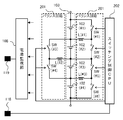
- the stack 103 and the battery monitoring unit 108 are the same as the parts having the same numbers in FIG. 1 or FIG. 1.
- the converter balance circuit 107 includes a balance circuit 201 and a switching control CPU 202.
- the balance circuit 201 includes a plurality of inductors L and a plurality of switching elements SW for, for example, four batteries 102 # 1 to # 4 constituting the stack 103.
- the first terminal of the inductor L of # 1 is connected to the common connection terminal of the batteries 102 of # 1 and # 2
- the inductor L of # 2 is connected to the common connection terminal of the batteries 102 of # 2 and # 3.
- the first terminal of the # 3 inductor L is connected to the common connection terminal of the # 3 and # 4 batteries 102, respectively.
- the second terminal of the # 1 inductor L is the common connection terminal for the # 1 and # 2 switching elements SW, and the second terminal of the # 2 inductor L is the common for the # 3 and # 4 switching elements SW.
- the second terminal of the # 3 inductor L is connected to the common connection terminal of the # 5 and # 6 switching elements SW.
- the output terminal side of the # 1 battery 102 is connected to the single connection terminal of the # 1 switching element SW.
- the common connection terminal of the batteries 102 of # 1 and # 2 is connected to the switching element SW of # 2.
- the common connection terminals of the # 2 and # 3 batteries 102 are connected to the common connection terminals of the switching elements SW of # 2 and # 5.
- the output terminal side of the # 4 battery 102 is connected to the single connection terminal of the # 6 switching element SW.
- the switching control CPU 202 is an oscillation circuit that oscillates a pulse signal having a predetermined frequency and duty ratio designated via the insulating element 120 from the main control CPU 116 on the low voltage system substrate 106 of FIG.
- Each switching element SW of # 1 to # 6 is, for example, an FET (field effect transistor), and performs a switching operation by a pulse signal from the switching control CPU 202.
- the battery monitoring unit 108 detects the voltages at both ends of each of the batteries # 1 to # 4 constituting the stack 103, and uses the detected voltage as a digital value via the insulating element 118 as shown in FIG. Output to the upper main control CPU 116.
- the main control CPU 116 designates a predetermined frequency and duty ratio to the switching control CPU 202 when determining that the balance control between the batteries 102 of # 1 and # 2 is performed, for example. Then, the switching elements SW of # 1 and # 2 are instructed to operate. For example, the main control CPU 116 (which may be the switching control CPU 202) determines that the voltage of the # 1 battery 102 is higher than the voltage of the # 2 battery 102 based on the voltage monitoring result of the battery monitoring unit 108. To do. In this case, first, energy is accumulated in the # 1 inductor L by discharging from the # 1 battery 102 by the on / off operation of the # 1 switching element SW.
- the main control CPU 116 determines that the voltage of the # 2 battery 102 is higher than the voltage of the # 1 battery 102 based on the voltage monitoring result of the battery monitoring unit 108. In this case, first, energy is accumulated in the # 1 inductor L by discharging from the # 2 battery 102 by the on / off operation of the # 2 switching element SW. Subsequently, the battery 102 of the energy # 1 stored in the inductor L of # 1 is charged by the on / off operation of the switching element SW of # 1 delayed by the duty ratio.
- the main control CPU 116 determines that the balance control between the # 2 and # 3 batteries 102 is to be performed, the main control CPU 116 designates a predetermined frequency and duty ratio to the switching control CPU 202, and # 3 and # 4. Instructing the switching element SW to operate. For example, the main control CPU 116 determines that the voltage of the # 2 battery 102 is higher than the voltage of the # 3 battery 102 based on the voltage monitoring result of the battery monitoring unit 108. In this case, first, by the ON / OFF operation of the switching element SW of # 3, the energy is accumulated in the inductor L of # 2 by discharging from the battery 102 of # 2.
- the battery # 3 of energy # 3 stored in the inductor L # 2 is charged by the on / off operation of the switching element SW # 4 delayed by the duty ratio.
- the main control CPU 116 determines that the voltage of the # 3 battery 102 is higher than the voltage of the # 2 battery 102 based on the voltage monitoring result of the battery monitoring unit 108. In this case, first, by the ON / OFF operation of the switching element SW of # 4, the energy is accumulated in the inductor L of # 2 by discharging from the battery 102 of # 3. Subsequently, the battery 102 of energy # 2 stored in the inductor L of # 2 is charged by the on / off operation of the switching element SW of # 3 delayed by the duty ratio.
- the main control CPU 116 determines that the balance control between the batteries # 3 and # 4 is to be performed, the main control CPU 116 designates a predetermined frequency and duty ratio to the switching control CPU 202, and # 5 and # 6. Instructing the switching element SW to operate. For example, the main control CPU 116 determines that the voltage of the # 3 battery 102 is higher than the voltage of the # 4 battery 102 based on the voltage monitoring result of the battery monitoring unit 108. In this case, energy is accumulated in the # 3 inductor L by discharging from the # 3 battery 102 by the on / off operation of the # 5 switching element SW.
- the battery 102 of energy # 4 stored in the inductor L of # 3 is charged by the on / off operation of the switching element SW of # 6 delayed by the duty ratio.
- the main control CPU 116 determines that the voltage of the # 4 battery 102 is higher than the voltage of the # 3 battery 102 based on the voltage monitoring result of the battery monitoring unit 108. In this case, energy is accumulated in the # 3 inductor L by discharging from the # 4 battery 102 by the on / off operation of the # 6 switching element SW. Subsequently, the battery 102 of the energy # 3 stored in the inductor L of # 3 is charged by the on / off operation of the switching element SW of # 5 delayed by the duty ratio.
- the converter balance circuit 107 determines that the balance control is necessary by the main control CPU 116 on the low voltage system board 106 as a result of the voltage monitoring of each battery 102 in the stack 103 by the battery monitoring unit 108.
- the switching control CPU 202 on the high voltage system substrate 104 causes the inductors L from # 1 to # 3 and the switching elements SW from # 1 to # 6 to be selectively operated sequentially.
- balance control is sequentially performed between the adjacent batteries 102 of the batteries 102 of # 1 to # 4, and the operation is repeated, so that the batteries 102 of # 1 to # 4 in the stack 103 are finally obtained.
- the voltage becomes uniform.
- the battery monitoring unit 108 is preferably mounted on the high voltage system board 104 in order to directly monitor the voltage and temperature of each battery 102 in each stack 103 of the battery block 101. .
- the balance circuit 201 is preferably mounted on the high voltage system substrate 104 in order to directly control each battery 102. Further, since the switching control CPU 202 supplies a pulse signal to the switching element SW, it is not desirable to have a very long signal path, and therefore it is desirable to be mounted on the high voltage system substrate 104. In this way, the battery monitoring unit 108 for monitoring the battery in the stack 103, the balance circuit 201 for performing equalization control in the stack 103, and the switching control CPU 202 include a high voltage system board corresponding to the stack 103.
- the main control CPU 116 on the low voltage system board 106 is based on the digital value of the voltage of each battery 102 detected by the battery monitoring unit 108 on each high voltage system board 104. Then, it is determined whether or not the voltage balance of the battery 102 is lost. Based on the determination result, first, the main control CPU 116 operates the switching control CPU 115 in the transbalance circuit 105 based on the control operation specifically described below, and the rough voltage between the stacks 103. Adjust the balance. Thereafter, based on an instruction from the main control CPU 116, the switching control CPU 202 (FIG. 2) in each converter balance circuit 107 operates each balance circuit 201 so that the voltage balance of each battery 102 in each stack 103 is uniform. I ’m going to be in a bad state. By finely performing such digital control, efficient cell balancing becomes possible, and the time to balance can be shortened.
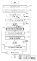
- FIG. 3 is a flowchart showing a control operation executed by the main control CPU 116 on the low voltage system substrate 106 of FIG.
- This control operation is realized as an operation in which a processor (not shown) in the main control CPU 116 executes a control program stored in a memory (not shown).
- This control program is executed once or repeatedly at a predetermined time interval, for example, when the vehicle equipped with the system of this embodiment is turned off or when idling is started.
- the main control CPU 116 uses each battery monitoring unit 108 (FIG. 1) connected to each converter balance circuit 107 to measure each terminal voltage of each battery 102 and obtains it as a digital value (step S301). ).
- the main control CPU 116 calculates the difference between the maximum voltage value and the minimum voltage value of each battery 102 (step S302).
- the main control CPU 116 determines whether or not the difference between the maximum voltage value and the minimum voltage value calculated in step S302 is equal to or greater than a predetermined threshold 1 (step S303). This threshold value 1 determines whether or not balance control is necessary.
- step S303 determines that balance control is unnecessary and ends the current balance control.
- step S303 If the result of determination in step S303 is that the difference is greater than or equal to the threshold value 1, the main control CPU 116 further calculates the voltage across each stack 103 based on the voltage monitoring result of each battery monitoring unit 108. Specifically, the main control CPU 116 adds all the voltage values at both ends of, for example, # 1 to # 4 batteries 102 (see FIG. 2) belonging to the stack 103 to each stack 103, and both ends of the stack 103 are added. Voltage. Then, the main control CPU 116 calculates the difference between the maximum voltage value and the minimum voltage value of each stack 103 (step S304).
- the main control CPU 116 determines whether or not the difference between the maximum voltage value and the minimum voltage value calculated in step S304 is equal to or greater than a predetermined threshold 2 (step S305). This threshold value 2 determines whether or not the balance control between stacks is necessary.
- step S305 If the difference is smaller than the threshold value 2 as a result of the determination in step S305, the main control CPU 116 determines that the inter-stack balance control is unnecessary, and shifts to the intra-stack balance control in and after step S307.
- step S305 If the difference is greater than or equal to the threshold value 2 as a result of the determination in step S305, the main control CPU 116 instructs the switching control CPU 202 in the transbalance circuit 105 on the high voltage system board in FIG. An activation instruction is issued (step S306). Details of this operation will be described later in the description of the flowchart of FIG.
- step S306 After the operation of the inter-stack balance control in step S306, or when it is determined in step S305 that the inter-stack balance control is not necessary (the difference is smaller than the threshold value 2), the intra-stack balance shown in steps S307 to S311 A control loop for balance control is executed.
- the main control CPU 116 sequentially selects the stacks 103 constituting the battery block 101 of FIG.
- the main control CPU 116 measures the battery voltage of each of the batteries 102 (FIG. 2) # 1 to # 4 in the selected stack 103 based on the voltage monitoring result of the battery monitoring unit 108 (step S307).
- the main control CPU 116 calculates the difference between the maximum voltage value and the minimum voltage value of the batteries 102 # 1 to # 4 in the selected stack 103 (step S308).
- the main control CPU 116 determines whether or not the difference between the maximum voltage value and the minimum voltage value calculated in step S308 is greater than or equal to a predetermined threshold 3 (step S309). This threshold value 3 determines whether or not the balance control within the stack is necessary.
- step S309 If it is determined in step S309 that the difference is smaller than the threshold 3, the main control CPU 116 determines that the balance control in the selected stack 103 is not necessary. As a result, the main control CPU 116 shifts to the determination process in step S311.
- step S 309 the main control CPU 116 activates in-stack balance control to the switching control CPU 202 in the converter balance circuit 107 on the high voltage system board 104 corresponding to the selected stack 103.
- the switching control CPU 202 sequentially specifies the # 1 and # 2 batteries 102, the # 2 and # 3 batteries 102, and the # 3 and # 4 batteries 102 in the stack 103 to which the switching control CPU 202 belongs. Then, the switching control CPU 202 operates the corresponding switching element SW for the designated pair of batteries 102 to execute the operation of the in-stack balance control (step S310). Details of this operation will be described later in the description of the flowchart of FIG.
- the main control CPU 116 determines whether or not the intra-stack balance control has been completed for all the stacks 103 at this time (step S311).
- the main control CPU 116 selects an unprocessed stack 103, returns to the processing of step S307, and within the stack for that stack 103. Perform balance control.
- the main control CPU 116 ends the current balance control process.
- FIG. 4 is activated by the switching control CPU 115 in the transbalance circuit 105 on the high voltage board based on the activation instruction of the inter-stack balance control in step S306 of FIG. 3 by the main control CPU 116 on the low voltage board 106.
- 5 is a flowchart showing a control operation.
- the switching control CPU 115 determines whether or not a current is flowing through the battery block 101 (FIG. 1) using an ammeter (not shown) connected to one end of the battery block 101 (step S401).
- the switching control CPU 115 determines that current is flowing through the battery block 101 in step S401, such as when the vehicle is idling, the switching control CPU 115 sets the voltage value for each stack 103 calculated in step S304 of FIG. 3 by the main control CPU 116, respectively.
- the internal resistance of each stack 103 is calculated by dividing by the current value measured in step S401 (step S402).
- the switching control CPU 115 obtains the temperature value of the battery block 101 from a temperature sensor (not shown), in particular, when it is determined in step S401 that no current is flowing through the battery block 101, such as when the vehicle is turned off.
- the switching control CPU 115 holds the voltage value (OCV: open circuit voltage) in the state where no current flows in each stack 103 calculated in step S304 of FIG. 3 and the above temperature value inside.
- OCV open circuit voltage
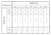
- the internal resistance is estimated with reference to the OCV-internal resistance map for each temperature (step S403).
- FIG. 5 is a diagram illustrating a data configuration example of an OCV-internal resistance map for each temperature. Internal resistance [m ⁇ ] is stored in each value of temperature [° C.] and OCV [V].
- the switching control CPU 115 calculates and sets the frequency and duty ratio of the pulse signal for the switching operation in the transformer balance circuit 105 of FIG. 1 from the value of the internal resistance in step S402 or S403 (step S404).
- a pulse signal is output from the switching control CPU 115 to the switching element 113, and switching control is executed (step S405).
- FIG. 6 shows the operation on the high voltage system board 104 corresponding to the stack 103 selected by the main control CPU 116 based on the start instruction of the balance control in the stack in step S310 of FIG. 3 by the main control CPU 116 on the low voltage system board 106.
- 7 is a flowchart showing a control operation started by a switching control CPU 202 in the converter balance circuit 107 of FIG.
- the switching control CPU 202 in FIG. 2 determines whether or not current is flowing through the battery block 101 (FIG. 1) using an ammeter (not shown) connected to one end of the battery block 101 (step S601). ).
- the switching control CPU 202 determines that current is flowing through the battery block 101 in step S601, such as when the vehicle is idling, the switching control CPU 202 calculates the voltage value for each battery 102 calculated by the main control CPU 116 in step S307 in FIG. Then, the internal resistance of each battery 102 is calculated by dividing by the current value measured in step S601 (step S602).
- the switching control CPU 202 determines that no current flows through the battery block 101 in step S601, for example, when the vehicle is turned off, the temperature value of the battery block 101 is acquired from a temperature sensor (not shown). Then, the switching control CPU 202 uses the voltage value (OCV) in the state where no current flows through each battery 102 calculated in step S307 in FIG. -The internal resistance is estimated with reference to the internal resistance map (step S603).
- OCV voltage value
- the switching control CPU 202 calculates and sets the frequency and duty ratio of the pulse signal for the switching operation in the selected switching element SW in the converter balance circuit 107 of FIG. 2 from the value of the internal resistance in step S602 or S603 ( Step S604). In this calculation process, calculation may be performed in consideration of temperature information from the temperature sensor. In addition, the pulse signal frequency and duty ratio may be set to arbitrary fixed values.
- a pulse signal is output from the switching control CPU 202 to the switching element SW, and switching control is executed (step S605).
- the transformer balance circuit 105 may have any configuration as long as an active balance configuration that can equalize the potential difference between the stacks 103 is employed. Further, the converter balance circuit 107 may have any configuration as long as an active balance configuration is adopted that can equalize the potential difference between the batteries 102 in the stack 103.
- the direct control system for equalization control is modularized on the high-voltage system board, and the main control CPU for performing the overall equalization control is arranged on the low-voltage system board. easily copes with an increase in the number of series. Thereby, an increase in circuit scale can be suppressed.
- the modules of the high-voltage system board 104 may be added in units of the stack 103, and the overall equalization control is performed at a low voltage.
- the main control CPU 116 on the system board 106 may be used. Thereby, complication of control can be prevented.
Landscapes
- Engineering & Computer Science (AREA)
- Power Engineering (AREA)
- Life Sciences & Earth Sciences (AREA)
- Sustainable Development (AREA)
- Sustainable Energy (AREA)
- Transportation (AREA)
- Mechanical Engineering (AREA)
- Secondary Cells (AREA)
- Charge And Discharge Circuits For Batteries Or The Like (AREA)
Abstract
L'invention concerne un système d'équilibrage de batterie dans lequel l'augmentation de l'échelle d'un circuit d'équilibrage est évitée même lorsque le nombre de batteries connectées en série et comprises dans une batterie assemblée augmente. Une unité de surveillance de batterie (108), un circuit d'équilibrage de convertisseur (107), et le mécanisme de commande de commutation du circuit d'équilibrage de convertisseur (107) sont modularisés sur une carte haute tension (104) pour chaque assemblage (103). Un circuit d'équilibrage de transformateur (105) pour équilibrer les tensions entre les assemblages (103) et une unité centrale (CPU) de commande de commutation (115) pour réaliser une commande de commutation sur le circuit d'équilibrage de transformateur (105) sont disposés sur la carte haute tension. Par contraste, une CPU de commande principale (116) pour commander totalement l'équilibrage est disposée sur une carte basse tension (106). Une communication mutuelle est possible entre le côté carte basse tension et le côté carte haute tension par l'intermédiaire d'éléments isolants (118, 119, 120) pour maintenir une isolation électrique. La modularisation d'un système de commande directe pour une commande d'équilibrage sur la carte haute tension et la disposition de la CPU de commande principale sur la carte basse tension rendent possible de gérer facilement, par exemple, l'augmentation du nombre de batteries connectées en série.
Applications Claiming Priority (2)
| Application Number | Priority Date | Filing Date | Title |
|---|---|---|---|
| JP2012-094841 | 2012-04-18 | ||
| JP2012094841A JP2013223378A (ja) | 2012-04-18 | 2012-04-18 | 電池均等化システムおよび方法 |
Publications (1)
| Publication Number | Publication Date |
|---|---|
| WO2013157576A1 true WO2013157576A1 (fr) | 2013-10-24 |
Family
ID=49383531
Family Applications (1)
| Application Number | Title | Priority Date | Filing Date |
|---|---|---|---|
| PCT/JP2013/061391 Ceased WO2013157576A1 (fr) | 2012-04-18 | 2013-04-17 | Système et procédé d'équilibrage de batterie |
Country Status (2)
| Country | Link |
|---|---|
| JP (1) | JP2013223378A (fr) |
| WO (1) | WO2013157576A1 (fr) |
Cited By (3)
| Publication number | Priority date | Publication date | Assignee | Title |
|---|---|---|---|---|
| CN110611300A (zh) * | 2019-09-30 | 2019-12-24 | 雅迪科技集团有限公司 | 一种电动车总线通讯高压短接关断保护电路 |
| EP3731367A4 (fr) * | 2017-12-19 | 2020-12-02 | SANYO Electric Co., Ltd. | Dispositif de gestion et système d'alimentation électrique |
| CN113764811A (zh) * | 2021-08-25 | 2021-12-07 | 东莞新能安科技有限公司 | 电池包、用电设备及电池包控制方法 |
Families Citing this family (4)
| Publication number | Priority date | Publication date | Assignee | Title |
|---|---|---|---|---|
| FR3014612B1 (fr) * | 2013-12-10 | 2015-12-04 | IFP Energies Nouvelles | Systeme et procede d'equilibrage de la charge d'une pluralite de modules de stockage d'energie |
| JP5996151B1 (ja) * | 2015-01-06 | 2016-09-21 | 三菱電機株式会社 | 電池システム |
| JP2016220449A (ja) * | 2015-05-22 | 2016-12-22 | 株式会社リコー | 二次電池システム、その制御方法及びプログラム |
| KR102749309B1 (ko) * | 2022-02-21 | 2025-01-02 | 주식회사 모큐라텍 | 액티브 밸런싱에 기초한 배터리 제어 시스템 |
Citations (2)
| Publication number | Priority date | Publication date | Assignee | Title |
|---|---|---|---|---|
| JP2006067742A (ja) * | 2004-08-27 | 2006-03-09 | Fdk Corp | 直列接続した2次電池のバランス補正装置およびその補正方法 |
| JP2010016928A (ja) * | 2008-07-01 | 2010-01-21 | Hitachi Ltd | 電池システム |
-
2012
- 2012-04-18 JP JP2012094841A patent/JP2013223378A/ja active Pending
-
2013
- 2013-04-17 WO PCT/JP2013/061391 patent/WO2013157576A1/fr not_active Ceased
Patent Citations (2)
| Publication number | Priority date | Publication date | Assignee | Title |
|---|---|---|---|---|
| JP2006067742A (ja) * | 2004-08-27 | 2006-03-09 | Fdk Corp | 直列接続した2次電池のバランス補正装置およびその補正方法 |
| JP2010016928A (ja) * | 2008-07-01 | 2010-01-21 | Hitachi Ltd | 電池システム |
Cited By (5)
| Publication number | Priority date | Publication date | Assignee | Title |
|---|---|---|---|---|
| EP3731367A4 (fr) * | 2017-12-19 | 2020-12-02 | SANYO Electric Co., Ltd. | Dispositif de gestion et système d'alimentation électrique |
| US11588185B2 (en) | 2017-12-19 | 2023-02-21 | Sanyo Electric Co., Ltd. | Management device and power supply system |
| CN110611300A (zh) * | 2019-09-30 | 2019-12-24 | 雅迪科技集团有限公司 | 一种电动车总线通讯高压短接关断保护电路 |
| CN110611300B (zh) * | 2019-09-30 | 2021-08-03 | 雅迪科技集团有限公司 | 一种电动车总线通讯高压短接关断保护电路 |
| CN113764811A (zh) * | 2021-08-25 | 2021-12-07 | 东莞新能安科技有限公司 | 电池包、用电设备及电池包控制方法 |
Also Published As
| Publication number | Publication date |
|---|---|
| JP2013223378A (ja) | 2013-10-28 |
Similar Documents
| Publication | Publication Date | Title |
|---|---|---|
| US8692508B2 (en) | Battery voltage monitoring device | |
| JP5744598B2 (ja) | バランス補正装置および蓄電システム | |
| JP5864320B2 (ja) | バランス補正装置および蓄電システム | |
| JP2013223378A (ja) | 電池均等化システムおよび方法 | |
| US20140009116A1 (en) | Balance correction apparatus and electric storage system | |
| WO2013154156A1 (fr) | Dispositif et procédé d'égalisation de piles | |
| WO2013146905A1 (fr) | Appareil et procédé d'égalisation de batterie | |
| JP2019030180A (ja) | 管理装置、蓄電装置、蓄電システム、及び、電気機器 | |
| JP2013005677A (ja) | セルバランス装置 | |
| JP2012191804A (ja) | バランス補正装置および蓄電システム | |
| US20120249058A1 (en) | Auxiliary battery charging apparatus | |
| JP2013116006A (ja) | 電池均等化装置および方法 | |
| JP2015519865A (ja) | バッテリの充電平衡 | |
| JP5187407B2 (ja) | 補機バッテリ充電装置 | |
| JP2013121242A (ja) | Soc推定装置及び電池パック | |
| US20100289453A1 (en) | Vehicle power system | |
| WO2013114757A1 (fr) | Dispositif et procédé d'égalisation entre accumulateurs | |
| JP2019161839A (ja) | 高電圧系と低電圧系とを備えた電源系 | |
| JP2013116008A (ja) | セルバランス装置 | |
| JP2013162661A (ja) | 補機電池への充電が可能な電池均等化装置および方法 | |
| WO2014073281A1 (fr) | Dispositif d'égalisation de tension | |
| WO2013187316A1 (fr) | Dispositif et procédé d'égalisation de tension | |
| JP5758234B2 (ja) | 蓄電システム | |
| JP7640012B2 (ja) | バッテリー装置およびバランシング方法 | |
| US9484762B2 (en) | Device and method for balancing battery cells |
Legal Events
| Date | Code | Title | Description |
|---|---|---|---|
| 121 | Ep: the epo has been informed by wipo that ep was designated in this application |
Ref document number: 13778785 Country of ref document: EP Kind code of ref document: A1 |
|
| NENP | Non-entry into the national phase |
Ref country code: DE |
|
| 122 | Ep: pct application non-entry in european phase |
Ref document number: 13778785 Country of ref document: EP Kind code of ref document: A1 |