WO2013161276A1 - Unité extérieure pour appareil de climatisation - Google Patents
Unité extérieure pour appareil de climatisation Download PDFInfo
- Publication number
- WO2013161276A1 WO2013161276A1 PCT/JP2013/002727 JP2013002727W WO2013161276A1 WO 2013161276 A1 WO2013161276 A1 WO 2013161276A1 JP 2013002727 W JP2013002727 W JP 2013002727W WO 2013161276 A1 WO2013161276 A1 WO 2013161276A1
- Authority
- WO
- WIPO (PCT)
- Prior art keywords
- collecting pipe
- header collecting
- outdoor unit
- heat exchanger
- air conditioner
- Prior art date
- Legal status (The legal status is an assumption and is not a legal conclusion. Google has not performed a legal analysis and makes no representation as to the accuracy of the status listed.)
- Ceased
Links
Images


Classifications
-
- F—MECHANICAL ENGINEERING; LIGHTING; HEATING; WEAPONS; BLASTING
- F28—HEAT EXCHANGE IN GENERAL
- F28F—DETAILS OF HEAT-EXCHANGE AND HEAT-TRANSFER APPARATUS, OF GENERAL APPLICATION
- F28F9/00—Casings; Header boxes; Auxiliary supports for elements; Auxiliary members within casings
- F28F9/007—Auxiliary supports for elements
- F28F9/013—Auxiliary supports for elements for tubes or tube-assemblies
-
- F—MECHANICAL ENGINEERING; LIGHTING; HEATING; WEAPONS; BLASTING
- F24—HEATING; RANGES; VENTILATING
- F24F—AIR-CONDITIONING; AIR-HUMIDIFICATION; VENTILATION; USE OF AIR CURRENTS FOR SCREENING
- F24F1/00—Room units for air-conditioning, e.g. separate or self-contained units or units receiving primary air from a central station
- F24F1/06—Separate outdoor units, e.g. outdoor unit to be linked to a separate room comprising a compressor and a heat exchanger
- F24F1/14—Heat exchangers specially adapted for separate outdoor units
- F24F1/16—Arrangement or mounting thereof
-
- F—MECHANICAL ENGINEERING; LIGHTING; HEATING; WEAPONS; BLASTING
- F24—HEATING; RANGES; VENTILATING
- F24F—AIR-CONDITIONING; AIR-HUMIDIFICATION; VENTILATION; USE OF AIR CURRENTS FOR SCREENING
- F24F1/00—Room units for air-conditioning, e.g. separate or self-contained units or units receiving primary air from a central station
- F24F1/06—Separate outdoor units, e.g. outdoor unit to be linked to a separate room comprising a compressor and a heat exchanger
- F24F1/40—Vibration or noise prevention at outdoor units
-
- F—MECHANICAL ENGINEERING; LIGHTING; HEATING; WEAPONS; BLASTING
- F28—HEAT EXCHANGE IN GENERAL
- F28D—HEAT-EXCHANGE APPARATUS, NOT PROVIDED FOR IN ANOTHER SUBCLASS, IN WHICH THE HEAT-EXCHANGE MEDIA DO NOT COME INTO DIRECT CONTACT
- F28D1/00—Heat-exchange apparatus having stationary conduit assemblies for one heat-exchange medium only, the media being in contact with different sides of the conduit wall, in which the other heat-exchange medium is a large body of fluid, e.g. domestic or motor car radiators
- F28D1/02—Heat-exchange apparatus having stationary conduit assemblies for one heat-exchange medium only, the media being in contact with different sides of the conduit wall, in which the other heat-exchange medium is a large body of fluid, e.g. domestic or motor car radiators with heat-exchange conduits immersed in the body of fluid
- F28D1/04—Heat-exchange apparatus having stationary conduit assemblies for one heat-exchange medium only, the media being in contact with different sides of the conduit wall, in which the other heat-exchange medium is a large body of fluid, e.g. domestic or motor car radiators with heat-exchange conduits immersed in the body of fluid with tubular conduits
- F28D1/047—Heat-exchange apparatus having stationary conduit assemblies for one heat-exchange medium only, the media being in contact with different sides of the conduit wall, in which the other heat-exchange medium is a large body of fluid, e.g. domestic or motor car radiators with heat-exchange conduits immersed in the body of fluid with tubular conduits the conduits being bent, e.g. in a serpentine or zig-zag
- F28D1/0471—Heat-exchange apparatus having stationary conduit assemblies for one heat-exchange medium only, the media being in contact with different sides of the conduit wall, in which the other heat-exchange medium is a large body of fluid, e.g. domestic or motor car radiators with heat-exchange conduits immersed in the body of fluid with tubular conduits the conduits being bent, e.g. in a serpentine or zig-zag the conduits having a non-circular cross-section
-
- F—MECHANICAL ENGINEERING; LIGHTING; HEATING; WEAPONS; BLASTING
- F28—HEAT EXCHANGE IN GENERAL
- F28D—HEAT-EXCHANGE APPARATUS, NOT PROVIDED FOR IN ANOTHER SUBCLASS, IN WHICH THE HEAT-EXCHANGE MEDIA DO NOT COME INTO DIRECT CONTACT
- F28D1/00—Heat-exchange apparatus having stationary conduit assemblies for one heat-exchange medium only, the media being in contact with different sides of the conduit wall, in which the other heat-exchange medium is a large body of fluid, e.g. domestic or motor car radiators
- F28D1/02—Heat-exchange apparatus having stationary conduit assemblies for one heat-exchange medium only, the media being in contact with different sides of the conduit wall, in which the other heat-exchange medium is a large body of fluid, e.g. domestic or motor car radiators with heat-exchange conduits immersed in the body of fluid
- F28D1/04—Heat-exchange apparatus having stationary conduit assemblies for one heat-exchange medium only, the media being in contact with different sides of the conduit wall, in which the other heat-exchange medium is a large body of fluid, e.g. domestic or motor car radiators with heat-exchange conduits immersed in the body of fluid with tubular conduits
- F28D1/053—Heat-exchange apparatus having stationary conduit assemblies for one heat-exchange medium only, the media being in contact with different sides of the conduit wall, in which the other heat-exchange medium is a large body of fluid, e.g. domestic or motor car radiators with heat-exchange conduits immersed in the body of fluid with tubular conduits the conduits being straight
- F28D1/0535—Heat-exchange apparatus having stationary conduit assemblies for one heat-exchange medium only, the media being in contact with different sides of the conduit wall, in which the other heat-exchange medium is a large body of fluid, e.g. domestic or motor car radiators with heat-exchange conduits immersed in the body of fluid with tubular conduits the conduits being straight the conduits having a non-circular cross-section
- F28D1/05366—Assemblies of conduits connected to common headers, e.g. core type radiators
- F28D1/05391—Assemblies of conduits connected to common headers, e.g. core type radiators with multiple rows of conduits or with multi-channel conduits combined with a particular flow pattern, e.g. multi-row multi-stage radiators
-
- F—MECHANICAL ENGINEERING; LIGHTING; HEATING; WEAPONS; BLASTING
- F28—HEAT EXCHANGE IN GENERAL
- F28F—DETAILS OF HEAT-EXCHANGE AND HEAT-TRANSFER APPARATUS, OF GENERAL APPLICATION
- F28F9/00—Casings; Header boxes; Auxiliary supports for elements; Auxiliary members within casings
- F28F9/001—Casings in the form of plate-like arrangements; Frames enclosing a heat exchange core
- F28F9/002—Casings in the form of plate-like arrangements; Frames enclosing a heat exchange core with fastening means for other structures
-
- F—MECHANICAL ENGINEERING; LIGHTING; HEATING; WEAPONS; BLASTING
- F28—HEAT EXCHANGE IN GENERAL
- F28D—HEAT-EXCHANGE APPARATUS, NOT PROVIDED FOR IN ANOTHER SUBCLASS, IN WHICH THE HEAT-EXCHANGE MEDIA DO NOT COME INTO DIRECT CONTACT
- F28D1/00—Heat-exchange apparatus having stationary conduit assemblies for one heat-exchange medium only, the media being in contact with different sides of the conduit wall, in which the other heat-exchange medium is a large body of fluid, e.g. domestic or motor car radiators
- F28D1/02—Heat-exchange apparatus having stationary conduit assemblies for one heat-exchange medium only, the media being in contact with different sides of the conduit wall, in which the other heat-exchange medium is a large body of fluid, e.g. domestic or motor car radiators with heat-exchange conduits immersed in the body of fluid
- F28D2001/0253—Particular components
- F28D2001/026—Cores
- F28D2001/0273—Cores having special shape, e.g. curved, annular
-
- F—MECHANICAL ENGINEERING; LIGHTING; HEATING; WEAPONS; BLASTING
- F28—HEAT EXCHANGE IN GENERAL
- F28D—HEAT-EXCHANGE APPARATUS, NOT PROVIDED FOR IN ANOTHER SUBCLASS, IN WHICH THE HEAT-EXCHANGE MEDIA DO NOT COME INTO DIRECT CONTACT
- F28D21/00—Heat-exchange apparatus not covered by any of the groups F28D1/00 - F28D20/00
- F28D2021/0019—Other heat exchangers for particular applications; Heat exchange systems not otherwise provided for
- F28D2021/0068—Other heat exchangers for particular applications; Heat exchange systems not otherwise provided for for refrigerant cycles
-
- F—MECHANICAL ENGINEERING; LIGHTING; HEATING; WEAPONS; BLASTING
- F28—HEAT EXCHANGE IN GENERAL
- F28F—DETAILS OF HEAT-EXCHANGE AND HEAT-TRANSFER APPARATUS, OF GENERAL APPLICATION
- F28F2215/00—Fins
- F28F2215/12—Fins with U-shaped slots for laterally inserting conduits
-
- F—MECHANICAL ENGINEERING; LIGHTING; HEATING; WEAPONS; BLASTING
- F28—HEAT EXCHANGE IN GENERAL
- F28F—DETAILS OF HEAT-EXCHANGE AND HEAT-TRANSFER APPARATUS, OF GENERAL APPLICATION
- F28F2265/00—Safety or protection arrangements; Arrangements for preventing malfunction
- F28F2265/30—Safety or protection arrangements; Arrangements for preventing malfunction for preventing vibrations
Definitions
- the present invention relates to an outdoor unit of an air conditioner, and particularly relates to measures against misalignment of a header collecting pipe of a mounted heat exchanger.
- the heat exchanger disclosed in Patent Document 1 is made of aluminum, and is arranged vertically between two header collecting pipes arranged upright, and one header at one end. It has a plurality of flat tubes inserted into the collecting pipe and the other end inserted into the other header collecting pipe, and a plurality of fins joined to the flat tube. In this heat exchanger, heat exchange is performed between the refrigerant flowing in the flat tube and the air passing between the fins.
- an insulating rubber member may be provided on the bottom plate of the casing to support the header collecting pipe from below.
- the heat exchanger is vibration-insulated, and further, the header collecting pipe and the bottom plate are insulated from each other to prevent the header collecting pipe from being corroded (electric corrosion).
- this rubber member is fixed with an adhesive, the condensed water dripped from the heat exchanger enters the adhesive and its adhesive strength is reduced, so the rubber member may be displaced. Further, when the refrigerant is condensed by the heat exchanger during the cooling operation, the rubber member may be softened and deformed by the heat of condensation. In such a case, there is a risk that the position of the header collecting pipe on the rubber member may be greatly displaced. There was a problem that occurred.
- the present invention has been made in view of such a point, and an object thereof is to prevent the generation of abnormal noise due to the displacement of the header collecting pipe.
- the first invention provides a housing (40), two header collecting pipes (51, 52) erected in the housing (40), and the two header collecting pipes (51, 52).
- a plurality of flat tubes (53) having one end inserted into one header collecting pipe (51, 52) and the other end inserted into the other header collecting pipe (51, 52), It is intended for an outdoor unit of an air conditioner including a heat exchanger (23) having a plurality of fins (55) joined to a flat tube (53).
- a support portion (91b) provided on the bottom plate (41) of the housing (40) and supporting the header collecting pipe (51, 52) from below, and the vicinity of the header collecting pipe (51, 52) And a restricting portion (101) for restricting movement of the header collecting pipe (51, 52).
- the restricting portion (101) is provided in the vicinity of the header collecting pipe (51, 52), and the movement of the header collecting pipe (51, 52) is restricted by the restricting portion (101). Therefore, for example, even if the posture of the heat exchanger (23) is inclined and the position of the header collecting pipe (51, 52) is largely displaced, the positional deviation of the header collecting pipe (51, 52) is restricted. Is suppressed by.
- the header collecting pipe (51, 52) is provided with an insulating circumscribed portion (91c) that circumscribes the header collecting pipe (51, 52), and the restricting portion (101) includes the circumscribed portion ( The movement of the header collecting pipe (51, 52) is regulated via 91c).
- the header collecting pipe (51, 52) is moved in a state where the insulating circumscribing part (91c) is interposed between the header collecting pipe (51, 52) and the restricting part (101). Is regulated. Therefore, the header collecting pipe (51, 52) and the restricting portion (101) are insulated by the circumscribed portion (91c).
- the restricting portion (101) restricts the movement of the header collecting pipe (51, 52) while being in surface contact with the circumscribed portion (91c). It is characterized by.
- the support portion (91b) has an insulating property, and the upper surface is in contact with the lower surface of the header collecting pipe (51, 52).
- the header collecting pipe (51, 52) is supported from below, and the circumscribed part (91c) is formed continuously from the support part (91b), and protrudes upward from the upper surface of the support part (91b). It is characterized by circumscribing the header collecting pipe (51, 52).
- the circumscribed portion (91c) and the support portion (91b) are integrally formed of an insulating material. Therefore, both the header collecting pipe (51, 52) and the bottom plate (41) and the header collecting pipe (51, 52) and the restricting portion (101) are insulated, and the number of parts is reduced.
- the restriction portion (101) is configured such that the header collecting pipe (51,52) is in direct contact with the restriction portion (101). ) Movement is restricted.
- the restricting portion (101) is substantially horizontal and is substantially perpendicular to the extending direction of the flat tube (53). The movement of the header collecting pipe (51, 52) is restricted.
- the heat exchanger (23) is inclined substantially in a direction that is substantially horizontal and substantially perpendicular to the extending direction of the flat tube (53), and the header collecting tube (51, 52) Misalignment is also likely to occur in that direction.
- the restricting portion (101) is provided in a direction in which the header collecting pipe (51, 52) is likely to be displaced. Therefore, the position shift of the 1st header collecting pipe (51) with high frequency is suppressed reliably.
- the restricting portion (101) is provided in the vicinity of the header collecting pipe (51, 52), and the movement of the header collecting pipe (51, 52) is restricted by the restricting portion (101). .
- the position shift of the header collecting pipe (51, 52) can be suppressed, and the posture of the outdoor heat exchanger (23) can be stably maintained.
- the posture of the outdoor heat exchanger (23) is inclined and the connection pipes (75, 76) are distorted, and the distortion of the compressor (21) is prevented from resonating and causing noise. be able to.
- the insulating outer peripheral portion (91c) is circumscribed to the header collecting pipe (51, 52), and the outer peripheral portion is interposed between the header collecting pipe (51, 52) and the restricting portion (101).
- the movement of the header collecting pipe (51, 52) was regulated with (91c) interposed.
- the header collecting pipe (51, 52) and the regulating part (101) can be insulated by the circumscribed part (91c), and the header collecting pipe (51, 52) can be prevented from being corroded (electric corrosion). it can.
- the movement of the header collecting pipe (51, 52) is regulated in a state where the regulating part (101) and the circumscribed part (91c) are in surface contact.
- the restriction state of the restricting portion (101) via the circumscribed portion (91c) can be stabilized, and the displacement of the header collecting pipe (51, 52) can be reliably suppressed, thereby preventing abnormal noise. Can increase the sex.
- the circumscribed portion (91c) and the support portion (91b) that supports the header collecting pipe (51, 52) from below are integrally formed of an insulating material.
- 51, 52) can be further prevented from corrosion (electric corrosion).
- the number of parts can be reduced to reduce the cost, and the parts can be miniaturized.
- the header collecting pipe (51, 52) is directly brought into contact with the restricting portion (101) to restrict the movement of the header collecting pipe (51, 52).
- the position accuracy of the header collecting pipe (51, 52) regulated by the regulating part (101) can be increased.
- the restricting portion (101) is provided in a direction in which the posture of the heat exchanger (23) is inclined and the header collecting pipe (51, 52) is likely to be displaced. As a result, it is possible to reliably suppress misalignment of the frequent header collecting pipes (51, 52) and to improve the certainty of noise prevention.
- FIG. 1 is a refrigerant circuit diagram illustrating a schematic configuration of the air conditioner according to the first embodiment.
- FIG. 2 is an external perspective view of the outdoor unit according to the first embodiment.
- FIG. 3 is a plan view of the outdoor unit according to the first embodiment with a top plate removed.
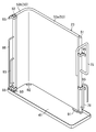
- FIG. 4 is a perspective view illustrating an installation state of the outdoor heat exchanger according to the first embodiment.
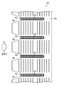
- FIG. 5 is a partial cross-sectional view of the outdoor heat exchanger according to the first embodiment.
- FIG. 6 is an enlarged cross-sectional view of a part of the VI-VI cross section of FIG.
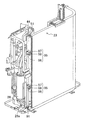
- FIG. 7 is a perspective view of the outdoor unit according to Embodiment 1 with a top plate and side plates removed.
- FIG. 1 is a refrigerant circuit diagram illustrating a schematic configuration of the air conditioner according to the first embodiment.
- FIG. 2 is an external perspective view of the outdoor unit according to the first embodiment.
- FIG. 3 is a plan view of the outdoor unit according to the first
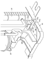
- FIG. 8 is an enlarged view in which the main part (positional displacement suppression structure) of FIG. 7 is enlarged.
- FIG. 9 is a plan view showing the misalignment suppressing structure of the first embodiment.
- 10 is a cross-sectional view taken along the line XX of FIG.
- FIG. 11 is a longitudinal sectional view showing a misregistration suppressing structure according to another embodiment.
- FIGS. 12A and 12B are vertical cross-sectional views showing a misregistration suppression structure according to another embodiment.
- FIGS. 13A and 13B are longitudinal cross-sectional views showing a misregistration suppressing structure according to another embodiment.
- FIG. 14 is a plan view showing a misregistration suppression structure according to another embodiment.
- Embodiment 1 of the Invention A first embodiment of the present invention will be described.
- the outdoor unit (2) of this embodiment constitutes a part of the air conditioner (1) and is installed outdoors, for example. Below, the whole structure of an air conditioner (1) is demonstrated first, and the structure of an outdoor unit (2) is demonstrated next.
- the air conditioner (10) includes an outdoor unit (11) and an indoor unit (12).
- the outdoor unit (11) and the indoor unit (12) are connected via a liquid side connecting pipe (13) and a gas side connecting pipe (14).
- a refrigerant circuit (20) is formed by the outdoor unit (11), the indoor unit (12), the liquid side connection pipe (13), and the gas side connection pipe (14).
- the refrigerant circuit (20) includes a compressor (21), a four-way switching valve (22), an outdoor heat exchanger (23), an expansion valve (24), an indoor heat exchanger (25), and an accumulator (26). ing.
- the compressor (21), the four-way switching valve (22), the outdoor heat exchanger (23), the expansion valve (24) and the accumulator (26) are accommodated in the outdoor unit (11).
- the outdoor unit (11) is provided with an outdoor fan (15) for supplying outdoor air to the outdoor heat exchanger (23).
- the indoor heat exchanger (25) is accommodated in the indoor unit (12).
- the indoor unit (12) is provided with an indoor fan (16) for supplying room air to the indoor heat exchanger (25).
- the compressor (21) has its discharge side connected to the first port of the four-way switching valve (22) and its suction side connected to the second port of the four-way switching valve (22) via the accumulator (26). Has been.
- the outdoor heat exchanger (23), the expansion valve (24), and the indoor heat exchanger are sequentially arranged from the third port to the fourth port of the four-way switching valve (22). (25) is arranged.
- Compressor (21) is a scroll type or rotary type hermetic compressor.
- the four-way selector valve (22) includes a first state (state indicated by a solid line in FIG. 1) in which the first port communicates with the third port and the second port communicates with the fourth port;
- the second port communicates with the fourth port and the second port communicates with the third port (a state indicated by a broken line in FIG. 1).
- the expansion valve (24) is a so-called electronic expansion valve.
- the outdoor heat exchanger (23) exchanges heat between the outdoor air and the refrigerant, and constitutes the heat exchanger of the present invention.
- the outdoor heat exchanger (23) will be described later.
- the indoor heat exchanger (25) exchanges heat between indoor air and the refrigerant.
- the indoor heat exchanger (25) is constituted by a so-called cross fin type fin-and-tube heat exchanger provided with a heat transfer tube which is a circular tube.
- the accumulator (26) gas-liquid separates the refrigerant and sucks only the gas refrigerant into the compressor (21).
- the air conditioner (10) selectively performs a cooling operation and a heating operation.
- the refrigeration cycle is performed with the four-way switching valve (22) set to the first state.
- the refrigerant circulates in the order of the outdoor heat exchanger (23), the expansion valve (24), the indoor heat exchanger (25), and the accumulator (26).
- the outdoor heat exchanger (23) the refrigerant discharged from the compressor (21) dissipates heat to the outdoor air and condenses.
- the indoor heat exchanger (25) the refrigerant expanded when passing through the expansion valve (24) absorbs heat from the indoor air and evaporates.
- the indoor unit (12) supplies the sucked room air to the indoor heat exchanger (25), and blows out the air cooled in the indoor heat exchanger (25) into the room.
- the refrigeration cycle is performed with the four-way switching valve (22) set to the second state.
- the refrigerant circulates in the order of the indoor heat exchanger (25), the expansion valve (24), the outdoor heat exchanger (23), and the accumulator (26).
- the indoor heat exchanger (25) the refrigerant discharged from the compressor (21) dissipates heat to the indoor air and condenses.
- the indoor unit (12) supplies the sucked indoor air to the indoor heat exchanger (25), and blows out the air heated in the indoor heat exchanger (25) into the room.
- the outdoor heat exchanger (23) the refrigerant expanded when passing through the expansion valve (24) absorbs heat from the outdoor air and evaporates.
- the outdoor unit (11) includes a casing (40).
- the casing (40) is an iron box formed in a vertically long and substantially rectangular parallelepiped shape, and constitutes the casing of the present invention.
- the casing (40) includes a bottom plate (41), a front plate (42a), a left plate (42b), a rear plate (42c) and a right plate (42d) that are erected on the bottom plate (41).
- a top plate (43) installed at the upper end of the side plates (42a to 42d), and the left-right direction is the longitudinal direction.
- a partition plate (44) is erected from the front plate (42a) to the rear (in the short direction) extending in an arc shape in plan view.
- the internal space of the casing (40) is partitioned by the partition plate (44) into a left blower chamber (S1) and a right machine chamber (S2).
- the blower room (S1) accommodates an outdoor heat exchanger (23) and an outdoor fan (15).
- the machine room (S2) includes a compressor (21), a four-way switching valve (22) (not shown in FIG. 3), an expansion valve (24) (not shown in FIG. 3), and an accumulator (26 ) And is housed.
- the rear plate (42c) of the casing (40) has a rear suction port (45a) on the fan chamber (S1) side, and the left plate (42b) has a left suction port (45b). .
- These two suction ports (45a, 45b) are for sucking air (outdoor air) into the blower chamber (S1).
- an air outlet (46) is opened on the fan chamber (S1) side.
- This blower outlet (46) is for blowing off air (outdoor air) from the inside of the blower chamber (S1) to the outside.
- a fan grill (47) is fitted into the air outlet (46).
- the outdoor heat exchanger (23) is formed in a substantially L shape in plan view, and faces the two suction ports (45a, 45b) in the blower chamber (S1). Is installed.
- the outdoor heat exchanger (23) includes a first header collecting pipe (51), a second header collecting pipe (52), a number of flat tubes (53), and a number of fins (55). ).
- the first header collecting pipe (51), the second header collecting pipe (52), the flat tube (53), and the fin (55) are all made of aluminum and are joined to each other by brazing.
- the first header collecting pipe (51) and the second header collecting pipe (52) are both formed in an elongated cylindrical shape with both ends closed. As shown in FIG. 3, in the fan chamber (S1), the first header collecting pipe (51) is erected between the rear side plate (42c) and the partition plate (44), and the second header collecting pipe ( 52) is erected on the corners of the front plate (42a) and the left plate (42b).
- the flat tube (53) is an elliptical heat transfer tube having a flat cross section, and a plurality of fluid passages (54) arranged in a row are formed inside.
- the plurality of flat tubes (53) are arranged in the vertical direction at regular intervals with each flat side surface facing each other, and are substantially parallel to each other.
- the flat tube (53) is formed in a substantially L shape in plan view and extends in the left-right direction (longitudinal direction) in FIG. 3, and in FIG. And a short side portion (53b) extending in the front-rear direction (short direction).
- the long side portion (53a) of the flat tube (53) faces the rear suction port (45a), and its end portion is inserted into the first header collecting pipe (51), and a plurality of fluid passages (54 ) Communicates with the internal space of the first header collecting pipe (51).
- the short side portion (53b) of the flat tube (53) faces the left suction port (45b), and its end portion is inserted into the second header collecting pipe (52), and a plurality of fluid passages ( 54) communicates with the internal space of the second header collecting pipe (52).
- the fin (55) is a vertically long plate-like fin formed by pressing a metal plate.
- the plurality of fins (55) are arranged in the extension direction of the flat tube (53) at regular intervals, and air (outdoor air) is placed between the adjacent fins (55) through the suction ports (45a, 45b).
- notches (56) are formed at regular intervals in the vertical direction on the inlet (45a, 45b) side, which is the windward side.
- the flat tube (53) is inserted in the leeward part of each notch part (56).
- the outdoor heat exchanger (23) is divided into an upper main heat exchange region (61) and a lower auxiliary heat exchange region (62), and each heat exchange region (61, 62 ) Is divided into three heat exchangers (61a to 61c, 62a to 62c).
- the first main heat exchange part (61a), the second main heat exchange part (61b), and the third main heat exchange part in order from bottom to top. (61c) is formed.
- auxiliary heat exchange region (62) in order from bottom to top, a first auxiliary heat exchange unit (62a), a second auxiliary heat exchange unit (62b), and a third auxiliary heat exchange unit (62c) Is formed.
- the number of flat tubes (53) constituting each main heat exchange section (61a to 61c) is larger than the number of flat tubes (53) constituting each auxiliary heat exchange section (62a to 62c).
- the internal space of the first header collecting pipe (51) is partitioned into an upper space (71) and a lower space (72) by a partition plate (51a).
- the upper space (71) communicates with all the flat tubes (53) constituting the main heat exchange region (61), and the lower space (72) is all the flat tubes constituting the auxiliary heat exchange region (62). Communicates with (53).
- a gas side connecting pipe (75) and a liquid side connecting pipe (76) are connected to the first header collecting pipe (51).
- One end of the gas side connecting pipe (75) is connected to the upper part of the first header collecting pipe (51) and communicates with the upper space (71), and the other end is connected to the third port of the four-way switching valve (22). It is connected.
- the liquid side connection pipe (76) has one end connected to the lower part of the first header collecting pipe (51) and communicating with the lower space (72), and the other end connected to the expansion valve (24).
- the internal space of the second header collecting pipe (52) is divided into a main communication space (81) corresponding to the main heat exchange area (61) and an auxiliary communication space (82) corresponding to the auxiliary heat exchange area (62).
- the main communication space (81) is divided into a first partial space (81a), a second partial space (81b), and a third partial space (81c) in order from the bottom to the top by the two partition plates (52a). It is partitioned.
- Each partial space (81a to 81c) communicates with all the flat tubes (53) constituting each main heat exchange section (61a to 61c).
- the auxiliary communication space (82) is divided into a fourth partial space (82a), a fifth partial space (82b), and a sixth partial space (82c) in order from the bottom to the top by the two partition plates (52b). It is partitioned.
- Each partial space (82a to 82c) communicates with all the flat tubes (53) constituting each auxiliary heat exchange section (62a to 62c).
- the first connection pipe (85) has one end connected to the second partial space (81b) and the other end connected to the fifth partial space (82b).
- the second connection pipe (86) has one end connected to the third partial space (81c) and the other end connected to the fourth partial space (82a).
- the first partial space (81a) and the sixth partial space (82c) form one continuous space.
- the outdoor heat exchanger (23) is supported in the casing (40) by three rubber members (91 to 93) and four attachment members (95).
- each mounting member (95) has an aluminum bracket (96), an iron mounting plate (97), and an insulating resin cover (98).
- the bracket (96) is fixed to each header collecting pipe (51, 52)
- the mounting plate (97) is fixed to each side plate (42b, 42c) of the casing (40)
- the bracket (98) 96) and the mounting plate (97) are fixed in an insulated state.
- the rubber members (91 to 93) are substantially plate-like rubber materials having insulating properties, and are adhesively fixed on the bottom plate (41) with an adhesive.
- the first rubber member (91) is provided between the rear plate (42c) and the partition plate (44), and supports the first header collecting pipe (51) from below.
- the second rubber member (92) is provided at corners of the rear side plate (42c) and the left side plate (42b), and supports the plurality of fins (55) from below.
- the third rubber member (93) is provided at the corner of the front side plate (42a) and the left side plate (42b), and supports the second header collecting pipe (52) from below.
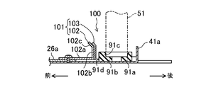
- the outdoor unit (2) of the present embodiment is provided with a misalignment suppressing structure (100) in order to suppress misalignment of the first header collecting pipe (51).
- the positional deviation suppressing structure (100) includes an accumulator leg (26a), a restricting portion (101), and the first rubber member (91).
- the accumulator leg (26a) is a support part for supporting the restricting portion (101), and is installed in the vicinity of the first header collecting pipe (51). Specifically, the accumulator leg (26a) is installed directly below the accumulator (26) positioned in front of the first header collecting pipe (51), and is fixed to the bottom surface of the bottom plate (41) with a screw. ) Is supported from below.
- the regulating part (101) is connected to the accumulator leg (26a).
- the restricting portion (101) restricts the movement of the first header collecting pipe (51) from the side and includes a restricting plate (102) and a buffer sheet (103).
- the regulation plate (102) is formed by bending an iron plate material, and has an extension portion (102a), a regulation surface portion (102b), and a guide portion (102c).
- the extension (102a) is connected to the accumulator leg (26a) by tightening the accumulator leg (26a) with a screw for fixing the accumulator leg (26a) to the bottom plate (41).
- the extension (102a) extends substantially horizontally from the accumulator leg (26a) toward the rear first header collecting pipe (51).
- the regulating surface portion (102b) is formed by bending the rear end of the extension portion (102a) (the end portion on the first header collecting pipe (51) side) at approximately 90 degrees, and extends upward in the vertical direction.
- the restriction surface portion (102b) is formed substantially parallel to the front surface (91d) (described later) of the insertion portion (91a) into which the lower end of the first header collecting pipe (51) is inserted.
- the movement of the first header collecting pipe (51) is restricted by the front surface (91d) of the insertion part (91a) coming into contact with the buffer sheet (103) on the restriction surface part (102b).
- the guide portion (102c) is formed by bending approximately 45 degrees forward from the upper end of the restriction surface portion (102b) (in a direction away from the first header collecting pipe (51)).
- the guide portion (102c) is formed so as to increase the gap between the restricting portion (101) and the rear wall (41a) on the rear side of the bottom plate (41), and is attached to the first header collecting pipe (51). Sometimes the first header collecting pipe (51) is guided to the gap.
- the buffer sheet (103) is a rubber sheet material, and is adhered to the rear surface (surface on the first header collecting pipe (51) side) of the regulation surface portion (102b) and the guide portion (102c).
- the buffer sheet (103) prevents the vibration of the accumulator (26) from propagating to the peripheral parts via the restricting plate (102).
- the first rubber member (91) is formed in a substantially rectangular shape in plan view, the side surface on the long side is in contact with the rear wall (41a) on the rear side of the bottom plate (41), and the back surface is It is fixed to the bottom surface of the bottom plate (41) with an adhesive.
- the insertion part (91a) is formed in the right side part of the 1st rubber member (91).
- the insertion part (91a) is a part that is located in the gap between the restriction part (101) and the standing wall (41a) and into which the lower end of the first header collecting pipe (51) is inserted.
- the insertion part (91a) has a support part (91b) and a circumscribed part (91c).
- the support part (91b) is a part that supports the first header collecting pipe (51) from below, and the upper surface is formed flat, and the lower surface of the first header collecting pipe (51) is in contact with the upper surface. ing.
- the circumscribed part (91c) is a part circumscribing the first header collecting pipe (51), and protrudes from the upper surface of the support part (91b) upward in a substantially annular shape.
- the insertion part (91a) has a front surface (91d) formed in the vertical direction. And the front surface (91d) of this insertion part (91a) and the buffer sheet
- the displacement of the first header collecting pipe (51) is often caused by the inclination of the outdoor heat exchanger (23).
- the outdoor heat exchanger (23) is substantially L-shaped in plan view as in the present embodiment, the outdoor heat exchanger (23) is positioned rearward (on the long side (53a) of the flat tube (53).
- the lower end of the first header collecting pipe (51) is displaced forward by tilting in the direction perpendicular to the extending direction.
- the restriction part (101) is provided in the vicinity of the first header collecting pipe (51).
- the lower end of the first header collecting pipe (51) is inserted into the insertion portion (91a), and the front surface (91d) of the insertion portion (91a) and the regulating portion (101) (buffer sheet (103)) are slightly It faces almost parallel through a gap. Therefore, when the first header collecting pipe (51) tries to move forward with the insertion portion (91a), the front surface (91d) of the insertion portion (91a) becomes the restriction portion (101) (buffer sheet (103)). In contact with each other, the first header collecting pipe (51) cannot move forward any more, and as a result, the forward displacement of the first header collecting pipe (51) is suppressed.
- a restricting portion (101) is provided in the vicinity of the first header collecting pipe (51), and the movement of the first header collecting pipe (51) is restricted by the restricting portion (101).
- the position shift of the 1st header collecting pipe (51) can be suppressed, and the attitude
- the posture of the outdoor heat exchanger (23) is inclined and the connection pipes (75, 76) are distorted, and the distortion of the compressor (21) is prevented from resonating and causing noise. be able to.
- the first header collecting pipe (51) is inserted into the insertion part (91a) of the insulating first rubber member (91). Then, the front surface (91d) of the insertion portion (91a) is brought into contact with the restriction portion (101), and the outer portion of the insertion portion (91a) between the first header collecting pipe (51) and the restriction portion (101) ( The movement of the first header collecting pipe (51) is regulated with 91c) in between.
- the first header collecting pipe (51) and the regulating part (101) can be insulated by the circumscribed part (91c), and corrosion (electric corrosion) of the aluminum first header collecting pipe (51) can be prevented. can do.
- the contact portion (front surface (91d)) on the insertion portion (91a) side and the contact portion (buffer sheet (103)) on the regulation portion (101) side are faced substantially parallel to each other, and the insertion portion ( 91a) and the regulating part (101) are brought into surface contact.
- the restriction state by the restriction part (101) via the insertion part (91a) can be stabilized, and the positional deviation of the first header collecting pipe (51) can be more reliably suppressed, thereby preventing abnormal noise. Certainty can be increased.
- the support portion (91b) that supports the first header collecting pipe (51) from below and the circumscribed portion (91c) that circumscribes the first header collecting pipe (51) have insulating properties.
- the first rubber member (91) is integrally formed. Accordingly, it is possible to insulate both the first header collecting pipe (51) and the bottom plate (41) and between the first header collecting pipe (51) and the restricting portion (101). Corrosion (electric corrosion) of the pipe (51) can be further prevented. Further, the number of parts can be reduced to reduce the cost, and the parts can be miniaturized.
- the direction of the outdoor heat exchanger (23) is inclined and the first header collecting pipe (51) is likely to be displaced (in this embodiment, in front of the first header collecting pipe (51)).
- the first header collecting pipe (51) is regulated. Thereby, the position shift of the 1st header collecting pipe (51) with a high frequency can be suppressed reliably, and the certainty of noise prevention can be improved.
- the movement of the first header collecting pipe (51) is regulated with the circumscribed part (91c) sandwiched between the first header collecting pipe (51) and the regulating part (101). .
- the restriction state of the first header collecting pipe (51) by the restricting section (101) is not limited to this.
- the movement of the header collecting pipe (51) may be restricted. In this case, since there is nothing intervening between the first header collecting pipe (51) and the regulating part (101), the positional accuracy of the header collecting pipe (51, 52) regulated by the regulating part (101) is increased. can do.
- the buffer sheet (103) is attached to the restriction plate (102) of the restriction portion (101).
- the configuration of the restricting portion (101) is not limited to this.
- the restricting portion (101) is configured only by the restricting plate (102) without attaching the buffer sheet (103).
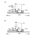
- a gap is provided between the restriction portion (101) and the insertion portion (91a). This gap is provided in order to increase the distance between the restricting portion (101) and the standing wall (41a) of the bottom plate (41) and facilitate the insertion of the first header collecting pipe (51) therein. .
- FIGS. 12A and 12B there is no gap between the restricting portion (101) and the insertion portion (91a), and the first header collecting pipe (51) is not displaced at all. A state may be formed.
- the support part (91b) which supports the 1st header collecting pipe (51) from the bottom, and the circumscribed part (91c) which circumscribes the 1st header collecting pipe (51) are made into the 1st rubber member. (91) is integrally formed.
- the support portion (91b) and the circumscribed portion (91c) are formed separately, and the first header collecting pipe (51), the restricting portion (101), The movement of the first header collecting pipe (51) may be restricted with the circumscribed portion (91c) sandwiched between them.
- seat (103)) by the side of a control part (101) are planar shape (planar view linear shape), respectively.
- the shape of each contact surface is not limited to this, and for example, as shown in FIG. 14, it may be formed in a circular arc shape in plan view along the outer peripheral surface of the first header collecting pipe (51). . Even in this case, the insertion portion (91a) and the restriction portion (101) can be brought into surface contact.
- the restricting portion (101) is connected to the accumulator leg (26a).
- the component that connects and supports the restricting portion (101) may be other than the accumulator leg (26a).
- the first header collecting pipe (51) is provided with the misregistration suppression structure (100).
- the second header collecting pipe (52) may be provided with a misalignment suppressing structure for suppressing misalignment.
- the present invention relates to an outdoor unit of an air conditioner, and is particularly useful for an outdoor unit equipped with an outdoor heat exchanger having a standing header collecting pipe.
- Air conditioner 11 Outdoor unit 23 Outdoor heat exchanger (heat exchanger) 40 Casing (housing) 41 Bottom plate 51 First header collecting pipe (header collecting pipe) 52 Second header collecting pipe (header collecting pipe) 53 Flat tube 55 fins 91b Support 91c Outer part 101 Regulatory Department
Landscapes
- Engineering & Computer Science (AREA)
- Mechanical Engineering (AREA)
- General Engineering & Computer Science (AREA)
- Physics & Mathematics (AREA)
- Thermal Sciences (AREA)
- Chemical & Material Sciences (AREA)
- Combustion & Propulsion (AREA)
- Other Air-Conditioning Systems (AREA)
- Heat-Exchange Devices With Radiators And Conduit Assemblies (AREA)
Priority Applications (3)
| Application Number | Priority Date | Filing Date | Title |
|---|---|---|---|
| EP13782026.2A EP2851624A4 (fr) | 2012-04-27 | 2013-04-23 | Unité extérieure pour appareil de climatisation |
| CN201380020298.6A CN104220815A (zh) | 2012-04-27 | 2013-04-23 | 空调机的室外机 |
| US14/391,942 US20150060029A1 (en) | 2012-04-27 | 2013-04-23 | Outdoor unit of air conditioner |
Applications Claiming Priority (2)
| Application Number | Priority Date | Filing Date | Title |
|---|---|---|---|
| JP2012-102646 | 2012-04-27 | ||
| JP2012102646A JP5447580B2 (ja) | 2012-04-27 | 2012-04-27 | 空調機の室外機 |
Publications (1)
| Publication Number | Publication Date |
|---|---|
| WO2013161276A1 true WO2013161276A1 (fr) | 2013-10-31 |
Family
ID=49482619
Family Applications (1)
| Application Number | Title | Priority Date | Filing Date |
|---|---|---|---|
| PCT/JP2013/002727 Ceased WO2013161276A1 (fr) | 2012-04-27 | 2013-04-23 | Unité extérieure pour appareil de climatisation |
Country Status (5)
| Country | Link |
|---|---|
| US (1) | US20150060029A1 (fr) |
| EP (1) | EP2851624A4 (fr) |
| JP (1) | JP5447580B2 (fr) |
| CN (1) | CN104220815A (fr) |
| WO (1) | WO2013161276A1 (fr) |
Cited By (2)
| Publication number | Priority date | Publication date | Assignee | Title |
|---|---|---|---|---|
| JP2018179395A (ja) * | 2017-04-12 | 2018-11-15 | 日立ジョンソンコントロールズ空調株式会社 | 室外機および冷凍サイクル装置 |
| JP2018185101A (ja) * | 2017-04-26 | 2018-11-22 | 東芝キヤリア株式会社 | 空気調和機の室外機 |
Families Citing this family (12)
| Publication number | Priority date | Publication date | Assignee | Title |
|---|---|---|---|---|
| JP2015021676A (ja) * | 2013-07-19 | 2015-02-02 | 三菱電機株式会社 | 室内熱交換器、室内機、室外熱交換器、室外機、及び空気調和機 |
| JP6137114B2 (ja) * | 2014-10-27 | 2017-05-31 | ダイキン工業株式会社 | 空気調和装置の熱源ユニット |
| JP6028815B2 (ja) * | 2015-01-19 | 2016-11-24 | ダイキン工業株式会社 | 空気調和装置の熱交換ユニット |
| JP6501071B2 (ja) * | 2015-12-28 | 2019-04-17 | 株式会社富士通ゼネラル | 空気調和機の室外機 |
| JP6288147B2 (ja) * | 2016-04-06 | 2018-03-07 | ダイキン工業株式会社 | 熱源ユニット |
| EP3452771B1 (fr) * | 2016-05-03 | 2022-08-31 | Carrier Corporation | Agencement d'échangeur thermique |
| CN109219723A (zh) * | 2016-06-07 | 2019-01-15 | 三菱电机株式会社 | 空调装置的室外机 |
| WO2018020536A1 (fr) * | 2016-07-25 | 2018-02-01 | 三菱電機株式会社 | Unité extérieure pour climatiseur |
| JP6583489B1 (ja) | 2018-06-15 | 2019-10-02 | ダイキン工業株式会社 | 熱交換ユニット |
| KR102812007B1 (ko) * | 2019-12-23 | 2025-05-23 | 삼성전자주식회사 | 공기조화기 |
| WO2024210022A1 (fr) * | 2023-04-03 | 2024-10-10 | 三菱電機株式会社 | Échangeur de chaleur et son procédé de fabrication |
| DE102023130327A1 (de) * | 2023-11-02 | 2025-05-08 | Stiebel Eltron Gmbh & Co. Kg | Luft-Wasser-Wärmepumpe mit einem Wärmeübertrager |
Citations (7)
| Publication number | Priority date | Publication date | Assignee | Title |
|---|---|---|---|---|
| JPH0473773U (fr) * | 1990-10-31 | 1992-06-29 | ||
| JPH04336397A (ja) * | 1991-05-13 | 1992-11-24 | Koatsu Gas Hoan Kyokai | ガス漏洩検知装置 |
| JPH05332694A (ja) * | 1992-06-04 | 1993-12-14 | Nippondenso Co Ltd | 熱交換器 |
| JPH0618012U (ja) * | 1992-08-19 | 1994-03-08 | サンデン株式会社 | 熱交換器のブラケット構造 |
| JP2010151375A (ja) * | 2008-12-25 | 2010-07-08 | Sharp Corp | 熱交換器 |
| JP2010249388A (ja) | 2009-04-15 | 2010-11-04 | Sharp Corp | 熱交換器及びそれを搭載した空気調和機 |
| JP2011145029A (ja) * | 2010-01-18 | 2011-07-28 | Sharp Corp | 空気調和機 |
Family Cites Families (3)
| Publication number | Priority date | Publication date | Assignee | Title |
|---|---|---|---|---|
| JPH0612381Y2 (ja) * | 1987-02-27 | 1994-03-30 | 昭和アルミニウム株式会社 | 熱交換器 |
| JPH0432698A (ja) * | 1990-05-28 | 1992-02-04 | Showa Alum Corp | 熱交換器の製造方法 |
| JP3133376B2 (ja) * | 1991-06-11 | 2001-02-05 | 昭和アルミニウム株式会社 | 熱交換器 |
-
2012
- 2012-04-27 JP JP2012102646A patent/JP5447580B2/ja not_active Expired - Fee Related
-
2013
- 2013-04-23 CN CN201380020298.6A patent/CN104220815A/zh active Pending
- 2013-04-23 WO PCT/JP2013/002727 patent/WO2013161276A1/fr not_active Ceased
- 2013-04-23 EP EP13782026.2A patent/EP2851624A4/fr not_active Withdrawn
- 2013-04-23 US US14/391,942 patent/US20150060029A1/en not_active Abandoned
Patent Citations (7)
| Publication number | Priority date | Publication date | Assignee | Title |
|---|---|---|---|---|
| JPH0473773U (fr) * | 1990-10-31 | 1992-06-29 | ||
| JPH04336397A (ja) * | 1991-05-13 | 1992-11-24 | Koatsu Gas Hoan Kyokai | ガス漏洩検知装置 |
| JPH05332694A (ja) * | 1992-06-04 | 1993-12-14 | Nippondenso Co Ltd | 熱交換器 |
| JPH0618012U (ja) * | 1992-08-19 | 1994-03-08 | サンデン株式会社 | 熱交換器のブラケット構造 |
| JP2010151375A (ja) * | 2008-12-25 | 2010-07-08 | Sharp Corp | 熱交換器 |
| JP2010249388A (ja) | 2009-04-15 | 2010-11-04 | Sharp Corp | 熱交換器及びそれを搭載した空気調和機 |
| JP2011145029A (ja) * | 2010-01-18 | 2011-07-28 | Sharp Corp | 空気調和機 |
Non-Patent Citations (1)
| Title |
|---|
| See also references of EP2851624A4 |
Cited By (2)
| Publication number | Priority date | Publication date | Assignee | Title |
|---|---|---|---|---|
| JP2018179395A (ja) * | 2017-04-12 | 2018-11-15 | 日立ジョンソンコントロールズ空調株式会社 | 室外機および冷凍サイクル装置 |
| JP2018185101A (ja) * | 2017-04-26 | 2018-11-22 | 東芝キヤリア株式会社 | 空気調和機の室外機 |
Also Published As
| Publication number | Publication date |
|---|---|
| EP2851624A1 (fr) | 2015-03-25 |
| JP5447580B2 (ja) | 2014-03-19 |
| EP2851624A4 (fr) | 2016-03-09 |
| US20150060029A1 (en) | 2015-03-05 |
| CN104220815A (zh) | 2014-12-17 |
| JP2013231526A (ja) | 2013-11-14 |
Similar Documents
| Publication | Publication Date | Title |
|---|---|---|
| JP5447580B2 (ja) | 空調機の室外機 | |
| CN103547867B (zh) | 空调装置的室外机 | |
| JP6361685B2 (ja) | 熱源ユニット | |
| JP6156323B2 (ja) | 熱交換器組立体および冷凍装置の室外ユニット | |
| WO2013080682A1 (fr) | Machine d'extérieur pour dispositif de climatisation | |
| JP6826805B2 (ja) | 冷凍装置の室外ユニット | |
| JP5708237B2 (ja) | 冷凍装置の室外ユニット | |
| JP4918902B2 (ja) | 空気調和機の室外機 | |
| JP2013113558A (ja) | 空気調和装置の室外機及びこれに用いる閉鎖弁用の支持部材 | |
| JP5104993B1 (ja) | 冷凍装置の室外ユニット | |
| JP6610691B2 (ja) | 熱源ユニット | |
| JP5720621B2 (ja) | 空調機の室外機 | |
| CN202835596U (zh) | 制冷装置的室外机组 | |
| JP2018087698A5 (fr) | ||
| JP2011174653A (ja) | 空気調和機の室外機 | |
| JP7137092B2 (ja) | 熱交換器 | |
| JP2016084977A (ja) | 空気調和装置の熱源ユニット | |
| JP6131762B2 (ja) | 空気調和装置の室外ユニット | |
| JP6954429B2 (ja) | 冷凍装置の室外ユニット | |
| JP2014240712A (ja) | 空気調和装置の室外ユニット | |
| JP6635131B2 (ja) | 空気調和装置の室外機 | |
| WO2026083543A1 (fr) | Unité intérieure pour climatiseur? et climatiseur | |
| JP2024002648A (ja) | 熱交換器、及びその熱交換器を備える空気調和装置の室内機 | |
| JP2019132546A (ja) | 空気調和装置の室外機 |
Legal Events
| Date | Code | Title | Description |
|---|---|---|---|
| 121 | Ep: the epo has been informed by wipo that ep was designated in this application |
Ref document number: 13782026 Country of ref document: EP Kind code of ref document: A1 |
|
| WWE | Wipo information: entry into national phase |
Ref document number: 14391942 Country of ref document: US |
|
| NENP | Non-entry into the national phase |
Ref country code: DE |
|
| REEP | Request for entry into the european phase |
Ref document number: 2013782026 Country of ref document: EP |
|
| WWE | Wipo information: entry into national phase |
Ref document number: 2013782026 Country of ref document: EP |