WO2013161385A1 - Unité de chemise autoportante et procédé de construction de réservoir - Google Patents
Unité de chemise autoportante et procédé de construction de réservoir Download PDFInfo
- Publication number
- WO2013161385A1 WO2013161385A1 PCT/JP2013/055509 JP2013055509W WO2013161385A1 WO 2013161385 A1 WO2013161385 A1 WO 2013161385A1 JP 2013055509 W JP2013055509 W JP 2013055509W WO 2013161385 A1 WO2013161385 A1 WO 2013161385A1
- Authority
- WO
- WIPO (PCT)
- Prior art keywords
- plate
- tank
- liner
- independent
- liner unit
- Prior art date
- Legal status (The legal status is an assumption and is not a legal conclusion. Google has not performed a legal analysis and makes no representation as to the accuracy of the status listed.)
- Ceased
Links
Images








Classifications
-
- E—FIXED CONSTRUCTIONS
- E04—BUILDING
- E04H—BUILDINGS OR LIKE STRUCTURES FOR PARTICULAR PURPOSES; SWIMMING OR SPLASH BATHS OR POOLS; MASTS; FENCING; TENTS OR CANOPIES, IN GENERAL
- E04H7/00—Construction or assembling of bulk storage containers employing civil engineering techniques in situ or off the site
- E04H7/02—Containers for fluids or gases; Supports therefor
- E04H7/18—Containers for fluids or gases; Supports therefor mainly of concrete, e.g. reinforced concrete, or other stone-like material
-
- F—MECHANICAL ENGINEERING; LIGHTING; HEATING; WEAPONS; BLASTING
- F17—STORING OR DISTRIBUTING GASES OR LIQUIDS
- F17C—VESSELS FOR CONTAINING OR STORING COMPRESSED, LIQUEFIED OR SOLIDIFIED GASES; FIXED-CAPACITY GAS-HOLDERS; FILLING VESSELS WITH, OR DISCHARGING FROM VESSELS, COMPRESSED, LIQUEFIED, OR SOLIDIFIED GASES
- F17C3/00—Vessels not under pressure
- F17C3/02—Vessels not under pressure with provision for thermal insulation
- F17C3/022—Land-based bulk storage containers
-
- B—PERFORMING OPERATIONS; TRANSPORTING
- B65—CONVEYING; PACKING; STORING; HANDLING THIN OR FILAMENTARY MATERIAL
- B65D—CONTAINERS FOR STORAGE OR TRANSPORT OF ARTICLES OR MATERIALS, e.g. BAGS, BARRELS, BOTTLES, BOXES, CANS, CARTONS, CRATES, DRUMS, JARS, TANKS, HOPPERS, FORWARDING CONTAINERS; ACCESSORIES, CLOSURES, OR FITTINGS THEREFOR; PACKAGING ELEMENTS; PACKAGES
- B65D90/00—Component parts, details or accessories for large containers
- B65D90/02—Wall construction
- B65D90/06—Coverings, e.g. for insulating purposes
-
- F—MECHANICAL ENGINEERING; LIGHTING; HEATING; WEAPONS; BLASTING
- F17—STORING OR DISTRIBUTING GASES OR LIQUIDS
- F17C—VESSELS FOR CONTAINING OR STORING COMPRESSED, LIQUEFIED OR SOLIDIFIED GASES; FIXED-CAPACITY GAS-HOLDERS; FILLING VESSELS WITH, OR DISCHARGING FROM VESSELS, COMPRESSED, LIQUEFIED, OR SOLIDIFIED GASES
- F17C1/00—Pressure vessels, e.g. gas cylinder, gas tank, replaceable cartridge
- F17C1/12—Pressure vessels, e.g. gas cylinder, gas tank, replaceable cartridge with provision for thermal insulation
-
- F—MECHANICAL ENGINEERING; LIGHTING; HEATING; WEAPONS; BLASTING
- F17—STORING OR DISTRIBUTING GASES OR LIQUIDS
- F17C—VESSELS FOR CONTAINING OR STORING COMPRESSED, LIQUEFIED OR SOLIDIFIED GASES; FIXED-CAPACITY GAS-HOLDERS; FILLING VESSELS WITH, OR DISCHARGING FROM VESSELS, COMPRESSED, LIQUEFIED, OR SOLIDIFIED GASES
- F17C3/00—Vessels not under pressure
- F17C3/02—Vessels not under pressure with provision for thermal insulation
- F17C3/04—Vessels not under pressure with provision for thermal insulation by insulating layers
-
- F—MECHANICAL ENGINEERING; LIGHTING; HEATING; WEAPONS; BLASTING
- F17—STORING OR DISTRIBUTING GASES OR LIQUIDS
- F17C—VESSELS FOR CONTAINING OR STORING COMPRESSED, LIQUEFIED OR SOLIDIFIED GASES; FIXED-CAPACITY GAS-HOLDERS; FILLING VESSELS WITH, OR DISCHARGING FROM VESSELS, COMPRESSED, LIQUEFIED, OR SOLIDIFIED GASES
- F17C2201/00—Vessel construction, in particular geometry, arrangement or size
- F17C2201/01—Shape
- F17C2201/0104—Shape cylindrical
- F17C2201/0109—Shape cylindrical with exteriorly curved end-piece
-
- F—MECHANICAL ENGINEERING; LIGHTING; HEATING; WEAPONS; BLASTING
- F17—STORING OR DISTRIBUTING GASES OR LIQUIDS
- F17C—VESSELS FOR CONTAINING OR STORING COMPRESSED, LIQUEFIED OR SOLIDIFIED GASES; FIXED-CAPACITY GAS-HOLDERS; FILLING VESSELS WITH, OR DISCHARGING FROM VESSELS, COMPRESSED, LIQUEFIED, OR SOLIDIFIED GASES
- F17C2201/00—Vessel construction, in particular geometry, arrangement or size
- F17C2201/01—Shape
- F17C2201/0104—Shape cylindrical
- F17C2201/0119—Shape cylindrical with flat end-piece
-
- F—MECHANICAL ENGINEERING; LIGHTING; HEATING; WEAPONS; BLASTING
- F17—STORING OR DISTRIBUTING GASES OR LIQUIDS
- F17C—VESSELS FOR CONTAINING OR STORING COMPRESSED, LIQUEFIED OR SOLIDIFIED GASES; FIXED-CAPACITY GAS-HOLDERS; FILLING VESSELS WITH, OR DISCHARGING FROM VESSELS, COMPRESSED, LIQUEFIED, OR SOLIDIFIED GASES
- F17C2201/00—Vessel construction, in particular geometry, arrangement or size
- F17C2201/03—Orientation
- F17C2201/032—Orientation with substantially vertical main axis
-
- F—MECHANICAL ENGINEERING; LIGHTING; HEATING; WEAPONS; BLASTING
- F17—STORING OR DISTRIBUTING GASES OR LIQUIDS
- F17C—VESSELS FOR CONTAINING OR STORING COMPRESSED, LIQUEFIED OR SOLIDIFIED GASES; FIXED-CAPACITY GAS-HOLDERS; FILLING VESSELS WITH, OR DISCHARGING FROM VESSELS, COMPRESSED, LIQUEFIED, OR SOLIDIFIED GASES
- F17C2201/00—Vessel construction, in particular geometry, arrangement or size
- F17C2201/05—Size
- F17C2201/052—Size large (>1000 m3)
-
- F—MECHANICAL ENGINEERING; LIGHTING; HEATING; WEAPONS; BLASTING
- F17—STORING OR DISTRIBUTING GASES OR LIQUIDS
- F17C—VESSELS FOR CONTAINING OR STORING COMPRESSED, LIQUEFIED OR SOLIDIFIED GASES; FIXED-CAPACITY GAS-HOLDERS; FILLING VESSELS WITH, OR DISCHARGING FROM VESSELS, COMPRESSED, LIQUEFIED, OR SOLIDIFIED GASES
- F17C2203/00—Vessel construction, in particular walls or details thereof
- F17C2203/03—Thermal insulations
- F17C2203/0304—Thermal insulations by solid means
- F17C2203/0329—Foam
- F17C2203/0333—Polyurethane
-
- F—MECHANICAL ENGINEERING; LIGHTING; HEATING; WEAPONS; BLASTING
- F17—STORING OR DISTRIBUTING GASES OR LIQUIDS
- F17C—VESSELS FOR CONTAINING OR STORING COMPRESSED, LIQUEFIED OR SOLIDIFIED GASES; FIXED-CAPACITY GAS-HOLDERS; FILLING VESSELS WITH, OR DISCHARGING FROM VESSELS, COMPRESSED, LIQUEFIED, OR SOLIDIFIED GASES
- F17C2203/00—Vessel construction, in particular walls or details thereof
- F17C2203/03—Thermal insulations
- F17C2203/0304—Thermal insulations by solid means
- F17C2203/0337—Granular
- F17C2203/0341—Perlite
-
- F—MECHANICAL ENGINEERING; LIGHTING; HEATING; WEAPONS; BLASTING
- F17—STORING OR DISTRIBUTING GASES OR LIQUIDS
- F17C—VESSELS FOR CONTAINING OR STORING COMPRESSED, LIQUEFIED OR SOLIDIFIED GASES; FIXED-CAPACITY GAS-HOLDERS; FILLING VESSELS WITH, OR DISCHARGING FROM VESSELS, COMPRESSED, LIQUEFIED, OR SOLIDIFIED GASES
- F17C2203/00—Vessel construction, in particular walls or details thereof
- F17C2203/03—Thermal insulations
- F17C2203/0304—Thermal insulations by solid means
- F17C2203/0345—Fibres
- F17C2203/035—Glass wool
-
- F—MECHANICAL ENGINEERING; LIGHTING; HEATING; WEAPONS; BLASTING
- F17—STORING OR DISTRIBUTING GASES OR LIQUIDS
- F17C—VESSELS FOR CONTAINING OR STORING COMPRESSED, LIQUEFIED OR SOLIDIFIED GASES; FIXED-CAPACITY GAS-HOLDERS; FILLING VESSELS WITH, OR DISCHARGING FROM VESSELS, COMPRESSED, LIQUEFIED, OR SOLIDIFIED GASES
- F17C2203/00—Vessel construction, in particular walls or details thereof
- F17C2203/06—Materials for walls or layers thereof; Properties or structures of walls or their materials
- F17C2203/0602—Wall structures; Special features thereof
- F17C2203/0612—Wall structures
- F17C2203/0626—Multiple walls
- F17C2203/0631—Three or more walls
-
- F—MECHANICAL ENGINEERING; LIGHTING; HEATING; WEAPONS; BLASTING
- F17—STORING OR DISTRIBUTING GASES OR LIQUIDS
- F17C—VESSELS FOR CONTAINING OR STORING COMPRESSED, LIQUEFIED OR SOLIDIFIED GASES; FIXED-CAPACITY GAS-HOLDERS; FILLING VESSELS WITH, OR DISCHARGING FROM VESSELS, COMPRESSED, LIQUEFIED, OR SOLIDIFIED GASES
- F17C2203/00—Vessel construction, in particular walls or details thereof
- F17C2203/06—Materials for walls or layers thereof; Properties or structures of walls or their materials
- F17C2203/0634—Materials for walls or layers thereof
- F17C2203/0636—Metals
- F17C2203/0639—Steels
- F17C2203/0643—Stainless steels
-
- F—MECHANICAL ENGINEERING; LIGHTING; HEATING; WEAPONS; BLASTING
- F17—STORING OR DISTRIBUTING GASES OR LIQUIDS
- F17C—VESSELS FOR CONTAINING OR STORING COMPRESSED, LIQUEFIED OR SOLIDIFIED GASES; FIXED-CAPACITY GAS-HOLDERS; FILLING VESSELS WITH, OR DISCHARGING FROM VESSELS, COMPRESSED, LIQUEFIED, OR SOLIDIFIED GASES
- F17C2203/00—Vessel construction, in particular walls or details thereof
- F17C2203/06—Materials for walls or layers thereof; Properties or structures of walls or their materials
- F17C2203/0634—Materials for walls or layers thereof
- F17C2203/0636—Metals
- F17C2203/0648—Alloys or compositions of metals
-
- F—MECHANICAL ENGINEERING; LIGHTING; HEATING; WEAPONS; BLASTING
- F17—STORING OR DISTRIBUTING GASES OR LIQUIDS
- F17C—VESSELS FOR CONTAINING OR STORING COMPRESSED, LIQUEFIED OR SOLIDIFIED GASES; FIXED-CAPACITY GAS-HOLDERS; FILLING VESSELS WITH, OR DISCHARGING FROM VESSELS, COMPRESSED, LIQUEFIED, OR SOLIDIFIED GASES
- F17C2203/00—Vessel construction, in particular walls or details thereof
- F17C2203/06—Materials for walls or layers thereof; Properties or structures of walls or their materials
- F17C2203/0634—Materials for walls or layers thereof
- F17C2203/0678—Concrete
-
- F—MECHANICAL ENGINEERING; LIGHTING; HEATING; WEAPONS; BLASTING
- F17—STORING OR DISTRIBUTING GASES OR LIQUIDS
- F17C—VESSELS FOR CONTAINING OR STORING COMPRESSED, LIQUEFIED OR SOLIDIFIED GASES; FIXED-CAPACITY GAS-HOLDERS; FILLING VESSELS WITH, OR DISCHARGING FROM VESSELS, COMPRESSED, LIQUEFIED, OR SOLIDIFIED GASES
- F17C2221/00—Handled fluid, in particular type of fluid
- F17C2221/03—Mixtures
- F17C2221/032—Hydrocarbons
- F17C2221/033—Methane, e.g. natural gas, CNG, LNG, GNL, GNC, PLNG
-
- F—MECHANICAL ENGINEERING; LIGHTING; HEATING; WEAPONS; BLASTING
- F17—STORING OR DISTRIBUTING GASES OR LIQUIDS
- F17C—VESSELS FOR CONTAINING OR STORING COMPRESSED, LIQUEFIED OR SOLIDIFIED GASES; FIXED-CAPACITY GAS-HOLDERS; FILLING VESSELS WITH, OR DISCHARGING FROM VESSELS, COMPRESSED, LIQUEFIED, OR SOLIDIFIED GASES
- F17C2223/00—Handled fluid before transfer, i.e. state of fluid when stored in the vessel or before transfer from the vessel
- F17C2223/01—Handled fluid before transfer, i.e. state of fluid when stored in the vessel or before transfer from the vessel characterised by the phase
- F17C2223/0146—Two-phase
- F17C2223/0153—Liquefied gas, e.g. LPG, GPL
- F17C2223/0161—Liquefied gas, e.g. LPG, GPL cryogenic, e.g. LNG, GNL, PLNG
-
- F—MECHANICAL ENGINEERING; LIGHTING; HEATING; WEAPONS; BLASTING
- F17—STORING OR DISTRIBUTING GASES OR LIQUIDS
- F17C—VESSELS FOR CONTAINING OR STORING COMPRESSED, LIQUEFIED OR SOLIDIFIED GASES; FIXED-CAPACITY GAS-HOLDERS; FILLING VESSELS WITH, OR DISCHARGING FROM VESSELS, COMPRESSED, LIQUEFIED, OR SOLIDIFIED GASES
- F17C2223/00—Handled fluid before transfer, i.e. state of fluid when stored in the vessel or before transfer from the vessel
- F17C2223/03—Handled fluid before transfer, i.e. state of fluid when stored in the vessel or before transfer from the vessel characterised by the pressure level
- F17C2223/033—Small pressure, e.g. for liquefied gas
-
- F—MECHANICAL ENGINEERING; LIGHTING; HEATING; WEAPONS; BLASTING
- F17—STORING OR DISTRIBUTING GASES OR LIQUIDS
- F17C—VESSELS FOR CONTAINING OR STORING COMPRESSED, LIQUEFIED OR SOLIDIFIED GASES; FIXED-CAPACITY GAS-HOLDERS; FILLING VESSELS WITH, OR DISCHARGING FROM VESSELS, COMPRESSED, LIQUEFIED, OR SOLIDIFIED GASES
- F17C2260/00—Purposes of gas storage and gas handling
- F17C2260/01—Improving mechanical properties or manufacturing
- F17C2260/013—Reducing manufacturing time or effort
-
- F—MECHANICAL ENGINEERING; LIGHTING; HEATING; WEAPONS; BLASTING
- F17—STORING OR DISTRIBUTING GASES OR LIQUIDS
- F17C—VESSELS FOR CONTAINING OR STORING COMPRESSED, LIQUEFIED OR SOLIDIFIED GASES; FIXED-CAPACITY GAS-HOLDERS; FILLING VESSELS WITH, OR DISCHARGING FROM VESSELS, COMPRESSED, LIQUEFIED, OR SOLIDIFIED GASES
- F17C2270/00—Applications
- F17C2270/01—Applications for fluid transport or storage
- F17C2270/0134—Applications for fluid transport or storage placed above the ground
- F17C2270/0136—Terminals
Definitions
- the present invention relates to an independent liner unit and a tank construction method.
- This application claims priority based on Japanese Patent Application No. 2012-101266 for which it applied to Japan on April 26, 2012, and uses the content here.
- a low-temperature liquefied gas such as LNG (Liquefied Natural Gas) is stored in a cylindrical double-shell tank having, for example, a metal inner tank and a concrete outer tank.
- LNG Liquefied Natural Gas
- a double-shell tank is generally formed by first dividing a concrete outer tank side plate into a plurality of stages in the height direction from the foundation, forming an outer tank roof inside, and lifting the outer tank roof.
- the inner tank side plate is constructed in the same manner in the height direction divided into a plurality of stages below.
- Patent Document 1 discloses a method of using a precon mold with an outer tank liner in which an outer tank liner plate and precast concrete are integrated. According to this method, the construction of the lower part of the outer tank and the formation of the internal structure of the tank are performed in parallel by installing the precon mold with the outer tank liner on the foundation and using it as a formwork for placing concrete. be able to.
- Patent Document 1 it is conceivable to apply Patent Document 1 to form a mold (independent liner unit) by integrating the outer tank liner plate and a part of the outer tank side plate.
- the weight of the integrated structure increases, which increases the burden of transportation work and increases the transportation cost. The handleability of the formwork will deteriorate.
- the present invention has been made in view of the above-described problems, and enables the shortening of the work period by performing the formation of the outer tank side plate and the formation of the tank internal structure in parallel, and the handling property of the independent liner unit.
- the purpose is to improve.
- the present invention adopts the following configuration as means for solving the above-described problems.
- the independent liner unit according to the first aspect of the present invention includes a plate-shaped outer tub liner plate, a plate-shaped secondary barrier plate, and a cold insulating material disposed between the outer tub liner plate and the secondary barrier plate. Layers are integrated.
- An independent liner unit according to a second aspect of the present invention is fixed to one or more of the outer tank liner plate, the secondary barrier plate, and the cold insulation material layer in the first aspect, and has improved rigidity. Reinforcing means to be provided.
- the reinforcing means is an anchor bolt that penetrates the outer tank liner plate, the secondary barrier plate, and the cold insulation material layer.
- the reinforcing means is a rib fixed to the outer tank liner plate in the second aspect.
- a tank construction method comprising: a step of standing the independent liner unit according to any one of the first to fourth aspects; and a concrete on the outer tank liner plate side of the independent liner unit.
- a step of forming the tank internal structure on the secondary barrier plate side of the independent liner unit is included.
- the independent liner unit is formed by the outer tank liner plate, the secondary barrier plate, and the cold insulation material layer. Since such an independent liner unit is not integrated with a concrete outer tub side plate, it can be reduced in weight compared to an independent liner unit with an outer tub side plate integrated, and handling is improved. . Furthermore, since the independent liner unit of the present invention can be used as a mold when forming a side plate made of concrete, the internal structure of the tank can be formed in parallel with the formation of the outer tank side plate. Therefore, according to the present invention, it is possible to shorten the work period by performing the formation of the outer tank side plate and the formation of the tank internal structure in parallel, and it is possible to improve the handleability of the independent liner unit.
- FIG. 1A It is a longitudinal section showing a schematic structure of an independent liner unit concerning one embodiment of the present invention. It is the arrow line view seen from the direction of arrow A of Drawing 1A which shows the schematic structure of the independent liner unit concerning one embodiment of the present invention. It is sectional drawing which shows typically schematic structure of the tank which has the independent liner unit which concerns on one Embodiment of this invention. It is a schematic diagram for demonstrating the construction method of the tank using the independent liner unit which concerns on one Embodiment of this invention. It is a schematic diagram for demonstrating the construction method of the tank using the independent liner unit which concerns on one Embodiment of this invention.
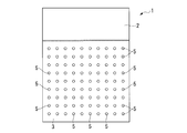
- FIG. 1A and 1B are diagrams showing a schematic configuration of the independent liner unit 1 of the present embodiment, FIG. 1A is a longitudinal sectional view, and FIG. 1B is an arrow view seen from the direction of arrow A in FIG. 1A. is there.
- the independent liner unit 1 of the present embodiment is configured by integrating an outer tank liner plate 2, a secondary barrier plate 3, a cold insulation material layer 4, and an anchor bolt 5 (reinforcing means). Is done.
- the outer tank liner plate 2 is a plate material made of stainless steel, for example, and constitutes a part of the outer tank liner 19 provided in the tank 10 described later. As shown in FIG. 1B, the outer tank liner plate 2 has the same width as the secondary barrier plate 3 and has a rectangular shape higher (longer) than the secondary barrier plate 3.
- the secondary barrier plate 3 is a plate material made of, for example, 9% nickel steel, and constitutes a part of the secondary barrier 17 included in the tank 10 described later. As shown in FIG. 1B, the secondary barrier plate 3 has the same width as the outer tank liner plate 2 and a substantially rectangular shape that is lower (shorter) than the outer tank liner plate 2. Further, the secondary barrier plate 3 is disposed to face the outer tank liner plate 2 with a certain interval in a state where the positions of the lower end of the outer tank liner plate 2 coincide with those of the outer tank liner plate 2. The upper end portion of the secondary barrier plate 3 is bent toward the outer tank liner plate 2 and is connected to the outer tank liner plate 2.
- the cold insulating material layer 4 is disposed between the outer tank liner plate 2 and the secondary barrier plate 3 and is supported by being sandwiched between the outer tank liner plate 2 and the secondary barrier plate 3.
- the cold insulation material layer 4 constitutes a part of the second cold insulation layer 18 provided in the tank 10 described later.
- the cold insulation material layer 4 is formed of a cold insulation material such as foam glass or PUF (hard urethane foam).
- Anchor bolt 5 penetrates outer tank liner plate 2, secondary barrier plate 3 and cold insulation material layer 4 and fastens them. As shown in FIG. 1B, a plurality of anchor bolts 5 are provided, for example, vertically and horizontally at a constant pitch. Such an anchor bolt 5 increases the fastening force of the outer tank liner plate 2, the secondary barrier plate 3 and the cold insulation material layer 4, and improves the rigidity of the independent liner unit 1.
- FIG. 2 is a cross-sectional view schematically showing a schematic configuration of a tank 10 including the independent liner unit 1 of the present embodiment.
- the corner of the tank 10 in which the independent liner unit 1 of the present embodiment is installed is partially enlarged.
- the tank 10 includes a foundation 11, an outer tub 12, a bottom portion 13, an inner tub 14, an elastic blanket 15, a first cold insulation layer 16, a secondary barrier 17, and a second cold insulation layer. 18, an outer tank liner 19, and an anchor strap 20.
- the tank 10 is also provided with equipment such as a payout pump and a manhole.
- the foundation 11 is a base made of reinforced concrete that supports the outer tub 12 and the inner tub 14.
- the outer tub 12 is a cylindrical concrete container formed directly on the foundation 11 so as to surround the inner tub 14.
- the outer tub 12 includes an outer tub side plate 12a that forms a peripheral surface, and an outer tub roof 12b that covers an upper portion of the outer tub side plate 12a.
- the outer tub 12 forms the outermost shell of the tank 10.
- Such a member existing inside the outer tub 12 is a tank internal structure in the present invention.
- the bottom portion 13 is formed on the foundation 11 in a region surrounded by the outer tank side plate 12a. As shown in the enlarged view of FIG. 2, the bottom portion 13 is provided on the bottom liner plate 13a installed in the lowermost layer, the dry sand layer 13b provided on the bottom liner plate 13a, and the dry sand layer 13b. The foamed glass layer 13c and two dry sand layers 13d provided on the foamed glass layer 13c are provided. Further, in the vicinity of the corner of the tank 10, the bottom portion 13 is, as shown in the enlarged view of FIG.
- a leveling concrete 13e provided on the bottom liner plate 13a
- a pearlite concrete block 13f provided on the leveling concrete 13e
- Reinforced concrete 13g is provided on the pearlite concrete block 13f and supports an annular plate 14d described later.
- the inner tank 14 is a cylindrical metal container (for example, 9% nickel steel) formed on the bottom 13 inside the outer tank 12.
- the inner tank 14 includes an inner tank side plate 14a that forms a peripheral surface, an inner tank roof 14b that covers the upper portion of the inner tank side plate 14a, an inner tank floor 14c that is disposed on the bottom 13, and an inner tank side plate 14a It is comprised from the annular plate 14d which connects the tank floor 14c.
- the elastic blanket 15 is installed outside the inner tank side plate 14a and surrounds the entire circumference of the inner tank side plate 14a.
- the first cold insulation layer 16 is installed outside the elastic blanket 15 and surrounds the entire circumference of the elastic blanket 15.
- the first cold insulation layer 16 is formed of, for example, pearlite.
- the secondary barrier 17 is installed so as to surround the lower part of the inner tank 14 with the elastic blanket 15 and the first cold insulation layer 16 interposed therebetween. If the inner tank 14 is damaged and LNG or the like leaks out, the LNG or the like is leaked. It is provided to stop the dam.
- the secondary barrier 17 is formed by joining a plurality of secondary barrier plates 3 of the independent liner unit 1 of the present embodiment in the circumferential direction of the inner tank 14.
- the second cold insulation layer 18 is installed outside the secondary barrier 17 and surrounds the entire circumference of the secondary barrier 17.
- the second cold insulation layer 18 is formed by joining a plurality of the cold insulation material layers 4 of the independent liner unit 1 of the present embodiment in the circumferential direction of the inner tank 14.
- the outer tank liner 19 is installed inside the outer tank side plate 12a and is provided on the entire surface of the outer tank side plate 12a.
- the lower part of the outer tank liner 19 is formed by joining a plurality of outer tank liner plates 2 of the independent liner unit 1 of the present embodiment in the circumferential direction of the inner tank 14.
- the anchor strap 20 is embedded between the inner tank side plate 14a and the outer tank side plate 12a, and supports the inner tank side plate 14a.
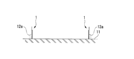
- the foundation 11 is constructed, and the independent liner unit 1 of this embodiment is erected on the foundation 11.
- the independent liner units 1 are arranged in a plurality of annular shapes when viewed from above, and are joined and arranged by welding.
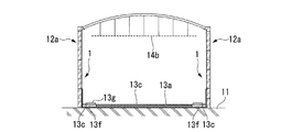
- the formation of the outer tub side plate 12a is started outside the independent liner unit 1, as shown in FIG. 3A.
- the outer tank side plate 12a is formed by stacking concrete blocks in a plurality of stages.
- the bottom liner plate 13a that is the tank internal structure is formed in parallel with the formation of the outer tub side plate 12a as shown in FIG. 3B. Installation of will begin. That is, in the construction method of the tank 10 using the independent liner unit 1 of the present embodiment, the formation of the tank internal structure can be started inside the independent liner unit 1 at the same time as the formation of the outer tank side plate 12a is started. it can.
- a rain avoidance 30 is installed in accordance with the corner of the inner tank 14, and a pearlite is provided below the rain avoidance 30 via the leveling concrete 13e.
- a concrete block 13f is installed. Since the leveling concrete 13e is thin, it is omitted in FIG. 3C.
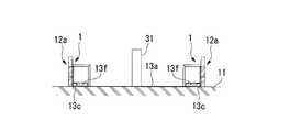
- FIG. 4A a part of the bottom 13 is formed between the pearlite concrete block 13f and the independent liner unit 1 in parallel with the formation of the outer tank side plate 12a.
- the bottom portion 13 formed between the pearlite concrete block 13f and the independent liner unit 1 is formed with a space for installing the anchor strap 20 therebetween.
- the mount frame 31 for forming the outer tank roof 12b is installed in the center of the foundation 11. As shown in FIG.
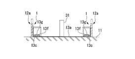
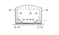
- reinforced concrete 13g is installed on the pearlite concrete block 13f. Furthermore, as shown in FIG. 4C, the outer tub roof 12 b is formed while being supported by the support columns 32. As shown in FIG. 4C, after the outer tank side plate 12 a is formed beyond the independent liner unit 1, the outer tank liner 19 is formed at a site beyond the independent liner unit 1.
- a support base 33 is formed on a part of the already formed outer tub side plate 12a to support the outer tub roof 12b, and the gantry 31 and the column 32 are removed. Is done.
- a dry sand layer 13b and a foamed glass layer 13c at the bottom 13 are formed. Since the dry sand layer 13b is thin, it is omitted in FIG. 5A.
- the inner tank roof 14b is formed so as to be suspended from the outer tank roof 12b. Then, after completion of the outer tub side plate 12a, as shown in FIG. 5C, the outer tub roof 12b and the inner tub roof 14b are raised by the air lifter and fixed to the top of the outer tub side plate 12a. Thereby, the outer tub 12 is completed.
- a crane 34 for forming the inner tank side plate 14 a is installed inside the outer tank 12.
- An annular plate 14d is disposed on the reinforced concrete 13g, and a dry sand layer 13d is formed on the foamed glass layer 13c.
- the inner tank 14 is completed by forming the inner tank side plate 14a and the inner tank floor 14c.
- the tank 10 is completed by installing the elastic blanket 15, the first cold insulation layer 16, and the anchor strap 20.
- the independent liner unit 1 of this embodiment is formed by an outer tank liner plate 2, a secondary barrier plate 3, and a cold insulation material layer 4. Since the independent liner unit 1 of this embodiment is not integrated with the concrete outer tub side plate 12a, it is lighter than a conventional independent liner unit with an integrated outer tub side plate. Can be handled, and handling is improved. Furthermore, since the independent liner unit 1 of the present embodiment can be used as a mold when forming a concrete outer tub side plate 12a as shown in FIGS. 3A to 3C, for example, the outer tub side plate 12a In parallel with the formation of the tank, the internal structure of the tank can be formed.
- the tank construction method using the independent liner unit 1 of the present embodiment the formation of the outer tank side plate 12a and the formation of the tank internal structure can be performed in parallel. That is, the tank construction method using the independent liner unit 1 of the present embodiment is a process of forming the tank internal structure on the secondary barrier plate 3 side of the independent liner unit 1 in parallel with the process of forming the outer tank side plate 12a. have. For this reason, the construction period can be shortened. Thus, according to the independent liner unit 1 of the present embodiment, the handleability is improved and the work period can be shortened.
- the outer tank liner plate 2, the secondary barrier plate 3, and the cold insulating material layer 4 are fastened, and the strength of the outer tank liner plate 2, the secondary barrier plate 3 and the cold insulating material layer 4 is increased.
- An anchor bolt 5 for improving is provided.
- the rigidity of the independent liner unit 1 can be changed depending on the arrangement pitch of the anchor bolts 5.
- the arrangement pitch of the anchor bolts 5 may be determined based on the hydraulic pressure of the concrete.
- the anchor bolts 5 may be installed at a higher density than the upper part in the lower part of the independent liner unit 1.
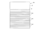
- FIGS. 7A and 7B are diagrams showing a schematic configuration of an independent liner unit 1A having a rib, FIG. 7A is a longitudinal sectional view, and FIG. 7B is an arrow view seen from the direction of arrow B in FIG. 7A. .
- this independent liner unit 1 ⁇ / b> A a plurality of ribs 6 are installed with respect to the outer tank liner plate 2.
- the rib 6 has the same length as the width of the outer tank liner plate 2, and a plurality of ribs 6 are installed at equal intervals in the height direction.
- the rigidity of the outer tank liner plate 2 is increased, and accordingly, the rigidity of the independent liner unit 1A is also increased. Even when such an independent liner unit 1A is used, it is possible to easily withstand the hydraulic pressure of concrete when used as a mold.
- the rib 6 may be installed at a high density with respect to the upper portion in the lower portion of the independent liner unit 1 ⁇ / b> A that receives a high hydraulic pressure.
- the tank when the tank is constructed, it is possible to shorten the work period by performing the formation of the outer tank side plate and the formation of the tank internal structure in parallel, and it is possible to improve the handleability of the independent liner unit. It becomes.
- inner tank floor, 14d ... annular plate, 15 ... elastic blanket, 16 ... first cold insulation layer, 17 ... secondary barrier, 18 ... second cold insulation layer, 1 ?? outer tub liner, 20 ?? anchor strap 31 ?? cradle, 32 ?? struts, 33 ?? support base, 34 ; cranes
Landscapes
- Engineering & Computer Science (AREA)
- Architecture (AREA)
- General Engineering & Computer Science (AREA)
- Mechanical Engineering (AREA)
- Physics & Mathematics (AREA)
- Thermal Sciences (AREA)
- Civil Engineering (AREA)
- Structural Engineering (AREA)
- Filling Or Discharging Of Gas Storage Vessels (AREA)
Priority Applications (9)
| Application Number | Priority Date | Filing Date | Title |
|---|---|---|---|
| SG11201406811PA SG11201406811PA (en) | 2012-04-26 | 2013-02-28 | Free-standing liner unit and method of building tank |
| CA2871473A CA2871473C (fr) | 2012-04-26 | 2013-02-28 | Unite de chemise autoportante et procede de construction de reservoir |
| CN201380020885.5A CN104220803B (zh) | 2012-04-26 | 2013-02-28 | 独立衬垫单元和罐的建设方法 |
| AU2013253963A AU2013253963B2 (en) | 2012-04-26 | 2013-02-28 | Free-standing liner unit and method for building tank |
| KR1020167027733A KR101745509B1 (ko) | 2012-04-26 | 2013-02-28 | 독립 라이너 유닛 및 탱크의 건설 방법 |
| US14/395,562 US10364939B2 (en) | 2012-04-26 | 2013-02-28 | Free-standing liner unit and method of building tank |
| KR1020147031018A KR20150000499A (ko) | 2012-04-26 | 2013-02-28 | 독립 라이너 유닛 및 탱크의 건설 방법 |
| RU2014146994/03A RU2583391C1 (ru) | 2012-04-26 | 2013-02-28 | Отдельно стоящий блок облицовки и способ строительства резервуара |
| IN9232DEN2014 IN2014DN09232A (fr) | 2012-04-26 | 2014-11-04 |
Applications Claiming Priority (2)
| Application Number | Priority Date | Filing Date | Title |
|---|---|---|---|
| JP2012101266A JP5998616B2 (ja) | 2012-04-26 | 2012-04-26 | 独立ライナユニット及びタンクの建設方法 |
| JP2012-101266 | 2012-04-26 |
Publications (1)
| Publication Number | Publication Date |
|---|---|
| WO2013161385A1 true WO2013161385A1 (fr) | 2013-10-31 |
Family
ID=49482725
Family Applications (1)
| Application Number | Title | Priority Date | Filing Date |
|---|---|---|---|
| PCT/JP2013/055509 Ceased WO2013161385A1 (fr) | 2012-04-26 | 2013-02-28 | Unité de chemise autoportante et procédé de construction de réservoir |
Country Status (12)
| Country | Link |
|---|---|
| US (1) | US10364939B2 (fr) |
| JP (1) | JP5998616B2 (fr) |
| KR (2) | KR20150000499A (fr) |
| CN (1) | CN104220803B (fr) |
| AU (1) | AU2013253963B2 (fr) |
| CA (1) | CA2871473C (fr) |
| IN (1) | IN2014DN09232A (fr) |
| MY (1) | MY168496A (fr) |
| RU (1) | RU2583391C1 (fr) |
| SG (1) | SG11201406811PA (fr) |
| TW (1) | TWI481538B (fr) |
| WO (1) | WO2013161385A1 (fr) |
Families Citing this family (12)
| Publication number | Priority date | Publication date | Assignee | Title |
|---|---|---|---|---|
| JP6127453B2 (ja) * | 2012-11-06 | 2017-05-17 | 株式会社Ihi | 円筒型タンクの構築方法 |
| JP6127459B2 (ja) * | 2012-11-12 | 2017-05-17 | 株式会社Ihi | 円筒型タンクの構築方法 |
| WO2016193913A1 (fr) * | 2015-06-03 | 2016-12-08 | Brl Patents Limited | Ensemble de sécurisation |
| DE102015008428A1 (de) * | 2015-06-30 | 2017-01-05 | Linde Aktiengesellschaft | Tank und Verfahren zum Herstellen eines Tanks |
| JP6465488B2 (ja) * | 2015-09-11 | 2019-02-06 | 株式会社Ihi | 円筒型タンクの構築方法 |
| JP2017128349A (ja) * | 2016-01-19 | 2017-07-27 | 株式会社Ihi | 二重殻タンクの施工方法 |
| JP2017150568A (ja) * | 2016-02-24 | 2017-08-31 | 株式会社Ihi | 低温液体タンク |
| CN107380780B (zh) * | 2017-08-31 | 2023-06-20 | 中国成达工程有限公司 | 一种双层夹套高温熔盐储罐 |
| KR102097154B1 (ko) * | 2018-01-10 | 2020-04-03 | 한국가스공사 | 구조가 개선된 9중량% Ni강 액화천연가스 저장탱크의 단열 구조체 및 이를 이용한 9중량% Ni강 액화천연가스 저장탱크의 단열재 충전방법 |
| KR102275074B1 (ko) * | 2020-01-09 | 2021-07-09 | 한국가스공사 | 유압을 이용한 액화 가스 탱크에서 내조의 부양 방법과 내조 부양을 이용한 액화 가스 탱크의 보강 방법 |
| KR200498179Y1 (ko) * | 2021-09-27 | 2024-07-22 | (주)포스코이앤씨 | 저온저장탱크 지지용 경량콘크리트 블록 |
| CN118953899B (zh) * | 2024-10-12 | 2025-01-24 | 上海联和日环能源科技有限公司 | 一种熔盐储罐、熔盐储能系统及其温度控制方法 |
Citations (5)
| Publication number | Priority date | Publication date | Assignee | Title |
|---|---|---|---|---|
| JPS542507A (en) * | 1977-06-08 | 1979-01-10 | Nippon Kokan Kk <Nkk> | Wall-panel of cold liquid underground tank |
| JPS58123119U (ja) * | 1982-02-16 | 1983-08-22 | 工藤 和子 | パネル補強装置 |
| JPH05180393A (ja) * | 1991-12-26 | 1993-07-20 | Osaka Gas Co Ltd | 低温貯槽における外槽の内装方法 |
| JP2002276894A (ja) * | 2001-03-21 | 2002-09-25 | Kajima Corp | 防液堤一体型低温タンクの冷熱抵抗緩和材の設置方法、防液堤一体型低温タンクおよび断熱パネル |
| JP2010106501A (ja) * | 2008-10-29 | 2010-05-13 | Takenaka Komuten Co Ltd | 低温貯槽の建設工法 |
Family Cites Families (14)
| Publication number | Priority date | Publication date | Assignee | Title |
|---|---|---|---|---|
| SU59507A1 (ru) * | 1940-02-04 | 1940-11-30 | Н.И. Покровский | Резервуар дл хранени нефтепродуктов |
| US3300943A (en) | 1964-04-29 | 1967-01-31 | Albert C Racine | Building system |
| US3583592A (en) * | 1968-11-05 | 1971-06-08 | Gen Am Transport | Cryogenic storage tank |
| JPS51129914A (en) | 1975-05-02 | 1976-11-11 | Nichias Corp | Heat insulation wall of low temperature liquified gas storage tank |
| JPS55117167A (en) * | 1979-11-24 | 1980-09-09 | Mita Ind Co Ltd | Moving frame control unit in electrophotographic copier |
| JPS58123119A (ja) | 1982-01-16 | 1983-07-22 | Sanyo Electric Co Ltd | マイクロコンピユ−タのリセツト回路 |
| FR2781557B1 (fr) | 1998-07-24 | 2000-09-15 | Gaz Transport & Technigaz | Perfectionnement pour une cuve etanche et thermiquement isolante a panneaux prefabriques |
| JP2001180793A (ja) | 1999-12-28 | 2001-07-03 | Ishikawajima Harima Heavy Ind Co Ltd | 地下式貯槽の側壁部構造 |
| JP2003240197A (ja) | 2002-02-15 | 2003-08-27 | Ishikawajima Harima Heavy Ind Co Ltd | 低温液化ガスタンク |
| US20060086741A1 (en) | 2004-10-21 | 2006-04-27 | Chicago Bridge & Iron Company | Low temperature/cryogenic liquid storage structure |
| FR2903165B1 (fr) | 2006-06-30 | 2008-09-05 | Gaz Transport & Technigaz | Panneau prefabrique avec film protecteur |
| US8603375B2 (en) | 2007-06-05 | 2013-12-10 | Chicago Bridge & Iron Company | Method of constructing a storage tank for cryogenic liquids |
| CN101343955B (zh) * | 2008-08-13 | 2010-04-14 | 深圳市普新科技有限公司 | 衬胆式混凝土罐体成型装置 |
| KR100964824B1 (ko) * | 2009-11-05 | 2010-06-23 | 한국가스공사 | 육상용 액화가스 저장탱크의 제작방법 |
-
2012
- 2012-04-26 JP JP2012101266A patent/JP5998616B2/ja not_active Expired - Fee Related
-
2013
- 2013-02-28 KR KR1020147031018A patent/KR20150000499A/ko not_active Ceased
- 2013-02-28 CN CN201380020885.5A patent/CN104220803B/zh not_active Expired - Fee Related
- 2013-02-28 CA CA2871473A patent/CA2871473C/fr not_active Expired - Fee Related
- 2013-02-28 KR KR1020167027733A patent/KR101745509B1/ko not_active Expired - Fee Related
- 2013-02-28 RU RU2014146994/03A patent/RU2583391C1/ru not_active IP Right Cessation
- 2013-02-28 US US14/395,562 patent/US10364939B2/en not_active Expired - Fee Related
- 2013-02-28 WO PCT/JP2013/055509 patent/WO2013161385A1/fr not_active Ceased
- 2013-02-28 SG SG11201406811PA patent/SG11201406811PA/en unknown
- 2013-02-28 MY MYPI2014703124A patent/MY168496A/en unknown
- 2013-02-28 AU AU2013253963A patent/AU2013253963B2/en not_active Ceased
- 2013-03-08 TW TW102108195A patent/TWI481538B/zh not_active IP Right Cessation
-
2014
- 2014-11-04 IN IN9232DEN2014 patent/IN2014DN09232A/en unknown
Patent Citations (5)
| Publication number | Priority date | Publication date | Assignee | Title |
|---|---|---|---|---|
| JPS542507A (en) * | 1977-06-08 | 1979-01-10 | Nippon Kokan Kk <Nkk> | Wall-panel of cold liquid underground tank |
| JPS58123119U (ja) * | 1982-02-16 | 1983-08-22 | 工藤 和子 | パネル補強装置 |
| JPH05180393A (ja) * | 1991-12-26 | 1993-07-20 | Osaka Gas Co Ltd | 低温貯槽における外槽の内装方法 |
| JP2002276894A (ja) * | 2001-03-21 | 2002-09-25 | Kajima Corp | 防液堤一体型低温タンクの冷熱抵抗緩和材の設置方法、防液堤一体型低温タンクおよび断熱パネル |
| JP2010106501A (ja) * | 2008-10-29 | 2010-05-13 | Takenaka Komuten Co Ltd | 低温貯槽の建設工法 |
Also Published As
| Publication number | Publication date |
|---|---|
| US10364939B2 (en) | 2019-07-30 |
| JP2013227050A (ja) | 2013-11-07 |
| IN2014DN09232A (fr) | 2015-07-10 |
| CN104220803B (zh) | 2016-12-28 |
| RU2583391C1 (ru) | 2016-05-10 |
| AU2013253963A1 (en) | 2014-11-13 |
| US20150053692A1 (en) | 2015-02-26 |
| MY168496A (en) | 2018-11-12 |
| KR101745509B1 (ko) | 2017-06-09 |
| CA2871473C (fr) | 2017-06-20 |
| SG11201406811PA (en) | 2014-11-27 |
| TWI481538B (zh) | 2015-04-21 |
| KR20150000499A (ko) | 2015-01-02 |
| TW201343501A (zh) | 2013-11-01 |
| AU2013253963B2 (en) | 2016-06-30 |
| JP5998616B2 (ja) | 2016-09-28 |
| CA2871473A1 (fr) | 2013-10-31 |
| CN104220803A (zh) | 2014-12-17 |
| KR20160120796A (ko) | 2016-10-18 |
Similar Documents
| Publication | Publication Date | Title |
|---|---|---|
| JP5998616B2 (ja) | 独立ライナユニット及びタンクの建設方法 | |
| CN104704180B (zh) | 圆筒型罐的构筑方法 | |
| JP6444585B2 (ja) | ガス貯蔵タンク及びlngタンクの施工方法 | |
| CN104769196B (zh) | 圆筒型罐的构筑方法 | |
| US20160083957A1 (en) | Method for constructing cylindrical tank | |
| WO2012099042A1 (fr) | Procédé pour construire un réservoir cylindrique | |
| WO2012137671A1 (fr) | Procédé pour construire un réservoir cylindrique | |
| JP2011122389A (ja) | 地上式低温タンク及びその構築方法 | |
| JP2014151926A (ja) | 地上タンクおよび地上タンクの施工方法 | |
| JP6136606B2 (ja) | 貯蔵タンクの施工方法 | |
| WO2014208672A1 (fr) | Procédé de construction d'un réservoir cylindrique | |
| JP6075004B2 (ja) | 地上式低温タンクの施工方法 | |
| WO2014208659A1 (fr) | Procédé de construction d'un réservoir cylindrique | |
| JP5516105B2 (ja) | 杭基礎式タンクの施工方法 | |
| TW201404992A (zh) | 圓筒型儲槽之構築方法 | |
| JP6330264B2 (ja) | プレストレスコンクリート構造物の施工方法 | |
| TWI608153B (zh) | 圓筒型槽的建構方法 | |
| JPWO2019193765A1 (ja) | 貯蔵タンクの施工装置 |
Legal Events
| Date | Code | Title | Description |
|---|---|---|---|
| 121 | Ep: the epo has been informed by wipo that ep was designated in this application |
Ref document number: 13782611 Country of ref document: EP Kind code of ref document: A1 |
|
| WWE | Wipo information: entry into national phase |
Ref document number: 14395562 Country of ref document: US |
|
| ENP | Entry into the national phase |
Ref document number: 2871473 Country of ref document: CA |
|
| NENP | Non-entry into the national phase |
Ref country code: DE |
|
| ENP | Entry into the national phase |
Ref document number: 20147031018 Country of ref document: KR Kind code of ref document: A |
|
| ENP | Entry into the national phase |
Ref document number: 2013253963 Country of ref document: AU Date of ref document: 20130228 Kind code of ref document: A |
|
| ENP | Entry into the national phase |
Ref document number: 2014146994 Country of ref document: RU Kind code of ref document: A |
|
| 122 | Ep: pct application non-entry in european phase |
Ref document number: 13782611 Country of ref document: EP Kind code of ref document: A1 |