WO2013161461A1 - Actionneur pour une opération d'allumage - Google Patents
Actionneur pour une opération d'allumage Download PDFInfo
- Publication number
- WO2013161461A1 WO2013161461A1 PCT/JP2013/058096 JP2013058096W WO2013161461A1 WO 2013161461 A1 WO2013161461 A1 WO 2013161461A1 JP 2013058096 W JP2013058096 W JP 2013058096W WO 2013161461 A1 WO2013161461 A1 WO 2013161461A1
- Authority
- WO
- WIPO (PCT)
- Prior art keywords
- cam
- ignition
- cam follower
- ignition operation
- operation actuator
- Prior art date
- Legal status (The legal status is an assumption and is not a legal conclusion. Google has not performed a legal analysis and makes no representation as to the accuracy of the status listed.)
- Ceased
Links
Images


Classifications
-
- G—PHYSICS
- G01—MEASURING; TESTING
- G01M—TESTING STATIC OR DYNAMIC BALANCE OF MACHINES OR STRUCTURES; TESTING OF STRUCTURES OR APPARATUS, NOT OTHERWISE PROVIDED FOR
- G01M17/00—Testing of vehicles
- G01M17/007—Wheeled or endless-tracked vehicles
- G01M17/0072—Wheeled or endless-tracked vehicles the wheels of the vehicle co-operating with rotatable rolls
- G01M17/0074—Details, e.g. roller construction, vehicle restraining devices
-
- F—MECHANICAL ENGINEERING; LIGHTING; HEATING; WEAPONS; BLASTING
- F16—ENGINEERING ELEMENTS AND UNITS; GENERAL MEASURES FOR PRODUCING AND MAINTAINING EFFECTIVE FUNCTIONING OF MACHINES OR INSTALLATIONS; THERMAL INSULATION IN GENERAL
- F16H—GEARING
- F16H53/00—Cams or cam-followers, e.g. rollers for gearing mechanisms
- F16H53/02—Single-track cams for single-revolution cycles; Camshafts with such cams
-
- G—PHYSICS
- G05—CONTROLLING; REGULATING
- G05G—CONTROL DEVICES OR SYSTEMS INSOFAR AS CHARACTERISED BY MECHANICAL FEATURES ONLY
- G05G1/00—Controlling members, e.g. knobs or handles; Assemblies or arrangements thereof; Indicating position of controlling members
- G05G1/02—Controlling members for hand actuation by linear movement, e.g. push buttons
-
- Y—GENERAL TAGGING OF NEW TECHNOLOGICAL DEVELOPMENTS; GENERAL TAGGING OF CROSS-SECTIONAL TECHNOLOGIES SPANNING OVER SEVERAL SECTIONS OF THE IPC; TECHNICAL SUBJECTS COVERED BY FORMER USPC CROSS-REFERENCE ART COLLECTIONS [XRACs] AND DIGESTS
- Y10—TECHNICAL SUBJECTS COVERED BY FORMER USPC
- Y10T—TECHNICAL SUBJECTS COVERED BY FORMER US CLASSIFICATION
- Y10T74/00—Machine element or mechanism
- Y10T74/13—Machine starters
- Y10T74/139—Cam operated
Definitions
- the present invention relates to an ignition operation actuator for performing an ignition operation, for example, when a vehicle running test is performed with a chassis dynamometer.
- a rotary ignition operation actuator for example, Patent Document 1 that rotates a rotary ignition and a push type ignition operation actuator (for example, Patent Document 2) that presses a push type ignition. )It has been known.
- a rotary ignition operation actuator 101 includes a drive unit 102 including a motor, a gear box, a rotation transmission coupling, and the like, a flexible shaft 103 that is rotationally driven by the drive unit 102, and a flexible shaft 103.
- An operation unit 104 that rotates the ignition key 105 and a chucking member 107 that attaches the drive unit 102 to the handle 106.
- the operation unit 104 inserts the end of the ignition key 105 between a pair of opposed pieces 108 a and 108 b of a key holding member 108 formed in a U shape, The ignition key 104 is pressed against the other piece 108b with the pressing screw 109 screwed into one piece 108a of the pieces 108a, 108b, thereby sandwiching the ignition key 104. Then, the ignition key 105 is rotated by the drive unit 102 and the flexible shaft 103 to perform an ignition operation.
- a pressing type ignition operation actuator (not shown) is a type in which a pressing type (push type) ignition is pressed with an operation button.
- Push-type ignition operation actuators use a motor as a drive source, convert the rotation of the motor into a straight movement of an operation button by a motion conversion mechanism, and operate a push-type ignition, and an air A system using a cylinder to press an operation button is known.
- the conventional ignition operation actuator has the following problems.
- Ignition operation actuators that use an air cylinder as the drive source require an air compressor for supplying air, piping, solenoid valves, electrical circuits for operating solenoid valves, etc., and are expensive.
- a rotary ignition operation actuator that uses a motor as a drive source uses a rack and pinion, ball screw, ball nut, etc. for the motor conversion mechanism, the rack and pinion, ball screw, ball nut, etc.
- the operation part is long and large, and may not be installed depending on the vehicle (in some vehicles, the ignition may be arranged on the back side of the steering wheel. Is too long to interfere with the handle).
- the conventional rotary type ignition operation actuator 101 is configured to be attached to the handle 106 by the chucking member 107, the play of the handle 106 causes the position of the operation portion 104 and the center of the ignition button. Deviation may occur.
- the conventional rotary type ignition operation actuator is configured exclusively as an ignition key actuator that rotates the ignition key, and the push type ignition operation actuator exclusively operates a push type ignition. Because it is configured as a push-type ignition-dedicated actuator, it is not possible to operate a push-type ignition key using a rotary-type ignition operation actuator. Conversely, a push-type ignition-operation actuator is used. Therefore, the rotary ignition key could not be pressed.
- the present invention relates to a press-type ignition operation actuator that uses a motor as a drive source and changes the rotation of the motor to a linear motion of a press button by a motion conversion mechanism to press the push-type ignition.
- a cam By using a cam, the ignition operation section is simplified.
- the present invention can be used as a push-type ignition operation actuator by sharing the drive unit of the rotary ignition operation actuator and the flexible shaft that is rotationally driven by the drive unit and replacing the operation unit. It is what I did.
- a drive unit having a motor and a rotational transmission coupling, a flexible shaft that is rotationally driven by the drive unit, and a push operation of a push-type ignition of the vehicle that is attached to the tip of the flexible shaft
- an operation unit is an ignition operation actuator comprising: a push button that pushes a push type ignition; and a motion conversion mechanism that converts the rotation of the flexible shaft into a straight movement of the push button.
- the motion conversion mechanism is constituted by a cam that is rotated by the flexible shaft and presses a cam engaging portion provided on the back side of the pressing button.
- the cam is provided with a cam follower that contacts the cam engaging portion and presses the cam engaging portion.
- the invention of claim 3 is the ignition operation actuator of claim 2,
- the cam follower is composed of a first cam follower provided at one end and a second cam follower provided at the other end with the rotation axis of the cam as a center.
- the ignition operation actuator according to the second or third aspect further comprises a spring that pushes back the pressing button when the pressing of the cam engaging portion by the cam follower is released.
- the invention of claim 5 is the ignition operation actuator of claim 4,
- the cam engaging portion includes a first cam engaging surface that is pressed by the first cam follower so as to face the first cam follower, and a second cam that is pressed by the second cam follower so as to face the second cam follower.
- An engagement surface, The first cam engagement surface and the second cam engagement surface are gradually separated from the cam follower as they go from the center to the side of the boundary between the first cam engagement surface and the second cam engagement surface. It is formed in the inclined surface which inclines.
- the operation portion is attached to a fixed frame fixed to a vehicle seat via an arm.
- a seventh aspect of the invention is the ignition operation actuator according to any one of the first to fifth aspects, wherein the operation portion is attached to a fixing jig and a fixed frame fixed to a vehicle seat via an arm. .
- the operation portion is attached to the inner surface of the vehicle with a suction cup.
- the conventional motion conversion mechanism includes a rack and pinion, a ball screw, a ball Compared to a case using a nut or the like, the structure of the operation unit can be simplified, and the operation unit can be reduced in size and weight.
- the ignition operation actuator according to claim 2 is configured such that a cam follower is attached to the cam, and a cam engaging portion provided on the back side of the push button is pressed from the cam follower, so that the cam follower rotates, The cam engaging portion is moved so as to slide, and the cam engaging portion is smoothly pressed.
- the cam follower includes a first cam follower provided at one end with the rotation axis of the cam as a center, and a second cam follower provided at the other end.
- the cam engagement portion is pressed by one cam follower by rotating the cam in one direction, and the cam engagement portion is pressed by the other cam follower by rotating (reversing) the cam in the other direction. can do.
- the cam engagement portion is opposed to the first cam follower and is opposed to the first cam follower, and is opposed to the second cam follower. And the second cam engagement surface pressed by the second cam follower, and gradually move from the cam follower as the first cam engagement surface and the second cam engagement surface are moved from the central portion to the side portion. Since it formed in the inclined surface which inclines in the space
- the ignition operation actuator according to the sixth aspect is configured to be attached via an arm to a fixed frame in which the operation portion is fixed to the seat of the vehicle, the center point of the press is shifted even if there is play in the handle. Can be prevented.
- the operation portion can be more reliably positioned by the arm of the fixed frame fixed to the vehicle seat and the fixing jig.
- the ignition operation actuator according to claim 8 can adsorb and fix the operation portion to the inner surface of the vehicle with a suction cup without using a free guide arm or the like.
- Explanatory drawing which shows a use condition.
- Explanatory drawing which shows the attachment state to the vehicle interior of an operation part.
- Explanatory drawing of a cam engaging part Explanatory drawing which shows the attachment state of a cam, and the state which the return coil spring is extending
- Explanatory drawing which shows the state in which the attachment state of a cam and the return coil spring are compressed.
- Explanatory drawing which shows the coupling
- Explanatory drawing which shows the case where an operation part is fixed to the vehicle body inner surface using a suction cup.
- the front view which shows a rotary operation part.
- FIG. 1 is an explanatory view showing a usage state of the ignition operation actuator 1.
- the ignition operation actuator 1 is attached to a drive unit 2 having a motor, a gear box, and a rotary transmission coupling (not shown), a flexible shaft 3 that is rotationally driven by the drive unit 2, and a distal end portion of the flexible shaft 3.
- an operation unit 4 that performs a pressing operation on a push-type ignition 117 (see FIG. 2) of the vehicle.
- the drive unit 2 and the operation unit 4 are attached to a fixed frame 111 that fixes a drive robot (not shown) to the vehicle seat 110, and prevents the center point of the press from shifting due to play of the handle 112. .
- the operation unit 4 is attached to the tip of the free guide arm 114 via the universal joint 113.
- a base end portion of the free guide arm 114 is attached to a clamp lever 116 provided on the fixed frame 111 by a clamp 115.
- the operation unit 4 is installed in a state where an operation button 5 described below is opposed to the push-type ignition 117 through a free guide arm 114.
- the fixing jig 118 indicated by a two-dot chain line is fitted into the unevenness around the ignition 117.
- the ignition actuator operation unit 4 can reliably press the center of the ignition 117.
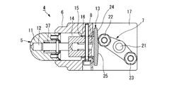
- FIG. 3 and 4 are cross-sectional views of the operation unit 4.
- FIG. 3 shows a state in which the operation button 5 is moved out to a position where the pressing of the pressing type ignition 117 is released.
- the operation unit 4 includes an operation button 5, a holder 6 on which the operation button 5 is slidably mounted, a cam 7 that presses the operation button 5 and protrudes to a position shown in FIG.
- a spring 8 is provided for returning the operation button 5 to the position shown in FIG. 3 when released.
- the spring 8 is optimally a coil spring, but may be another spring material.
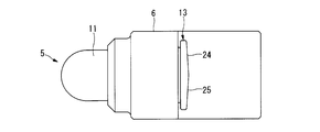
- the operation button 5 includes a button main body 11 that presses the press-type ignition 117, a rod 12 that has the button main body 11 attached to one end thereof, and is attached to the other end of the rod 12 and is pressed by the cam 7.
- the cam engaging portion 13 is provided.
- the holder 6 has a button main body accommodating portion 14 for accommodating the button main body 11 on one end side, and has a rod support portion 16 for slidably supporting the rod 12 via a thrust bearing 15 at a central portion.
- a cam accommodating portion 17 for accommodating the cam 7 is provided on the other end side.
- the cam 7 is formed in a substantially isosceles triangle shape, the central part is attached to the rotating shaft 21, and the first and second cam followers 22, 23 are attached to both sides, and either one of the cam followers 22, 23, the cam engaging part 13 is pressed.
- the cam engagement portion 13 is disposed to face the first cam follower 22 and is opposed to the first cam follower surface 24 pressed by the first cam follower 22 and the second cam follower 23. And a second cam engaging surface 25 that is pressed by the second cam follower 23.
- the first cam engagement surface 24 and the second cam engagement surface 25 are formed on inclined surfaces that gradually incline in a direction away from the cam follower as they go from the boundary portion to the side portion. ing.
- the button body 11 communicates with a rod mounting hole 26 into which the tip of the rod 12 is inserted and fixed, and one end of the rod mounting hole 26, and a spring receiver formed with a diameter larger than the diameter of the rod mounting hole 26.
- a hole 27 is provided.
- the rod 12 includes a first shaft portion 31, a second shaft portion 32 having a larger diameter than the first shaft portion 31, a bolt 34 attached to a bolt receiving hole 33 provided in the second shaft portion 32, A nut 35 is provided which is screwed onto the outer periphery of the head of the bolt 34 and clamps the cam engaging portion 13 with the second shaft portion 32.
- the distal end portion of the first shaft portion 31 is attached to the rod attachment hole 26. Further, a flange portion 36 is provided at the center portion of the first shaft portion 31. A spring (spring) 37 is interposed between the flange portion 36 and the end face of the coil spring receiving hole 27 to compress the button main body 11 and cause the button main body 11 to escape when overloaded. Yes. A ring-shaped member 38 is attached to the back side of the button main body 11 with a screw 39, and acts as a stopper with which the flange portion 36 abuts the ring-shaped member 38.
- the holder 6 is provided with an operation button rotation prevention pin 41 penetrating the thrust bearing 15 and the rod support 16.
- the operation button rotation prevention pin 41 is inserted into a slit provided in the second shaft portion 32 to prevent the rod 12 and the button body 11 from rotating, and moves the rod 12 and the button body 11 straightly.
- the spring 8 is interposed between the operation button rotation prevention pin 41 and the head of the bolt 34.
- the tip 3 a of the flexible shaft 3 is connected to an adapter 42 provided on the lower surface of the holder 6 by a fixing bolt 43.
- the rotation of the flexible shaft 3 is transmitted to the rotation shaft 21 of the cam 7 via the rotation transmission mechanism 44.
- the second cam follower 23 causes the second cam engagement of the cam engagement unit 13.
- the surface 25 is pressed, the operation button 5 is protruded, and the pressing type ignition 117 is pressed.
- FIG. 9 shows an embodiment of a method of fixing to the vehicle body inner surface 119 of the operation unit 4 without using the free guide arm 114.
- the fixing jig 118 is not fixed to the vehicle body inner surface 119 such as a dashboard, the free guide arm 119 is necessary, but the suction cup 50 is used as shown in FIG. Then, by firmly adsorbing to the inner surface 119 of the vehicle body, the center of pressing can be captured without using the free guide arm 114.
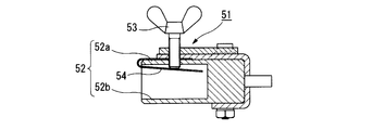
- the rotary operation unit 51 includes an end portion of an ignition key (not shown) inserted between a pair of opposed pieces 52a and 52b of a key holding member 52 formed in a U-shape, and the pair of pieces.
- the ignition key is pressed against the other piece 52b by the thumbscrew 53 and the leaf spring 54, which are screwed into one piece 52a of 52a, 52b, and the ignition key is sandwiched and held.
- the key holding member 52 includes an adapter 55 on one side surface, and is inserted into the adapter 55 by inserting the distal end 3a of the flexible shaft 3 and fixing the adapter 55 with a fixing screw 56, thereby being connected to the distal end 3a of the flexible shaft 3. Yes.
- the flexible shaft 3 rotates the rotary operation unit 51 and the ignition key to perform an ignition on / off operation.
Landscapes
- Engineering & Computer Science (AREA)
- Physics & Mathematics (AREA)
- General Physics & Mathematics (AREA)
- General Engineering & Computer Science (AREA)
- Mechanical Engineering (AREA)
- Automation & Control Theory (AREA)
- Lock And Its Accessories (AREA)
- Mechanical Control Devices (AREA)
- Seats For Vehicles (AREA)
Priority Applications (3)
| Application Number | Priority Date | Filing Date | Title |
|---|---|---|---|
| CN201380022086.1A CN104254765B (zh) | 2012-04-27 | 2013-03-21 | 用于点火操作的致动器 |
| KR1020147029685A KR101532624B1 (ko) | 2012-04-27 | 2013-03-21 | 이그니션 조작용 액튜에이터 |
| US14/396,921 US9599539B2 (en) | 2012-04-27 | 2013-03-21 | Actuator for ignition operation |
Applications Claiming Priority (2)
| Application Number | Priority Date | Filing Date | Title |
|---|---|---|---|
| JP2012-102064 | 2012-04-27 | ||
| JP2012102064A JP5556847B2 (ja) | 2012-04-27 | 2012-04-27 | イグニッション操作用アクチュエータ |
Publications (1)
| Publication Number | Publication Date |
|---|---|
| WO2013161461A1 true WO2013161461A1 (fr) | 2013-10-31 |
Family
ID=49482798
Family Applications (1)
| Application Number | Title | Priority Date | Filing Date |
|---|---|---|---|
| PCT/JP2013/058096 Ceased WO2013161461A1 (fr) | 2012-04-27 | 2013-03-21 | Actionneur pour une opération d'allumage |
Country Status (5)
| Country | Link |
|---|---|
| US (1) | US9599539B2 (fr) |
| JP (1) | JP5556847B2 (fr) |
| KR (1) | KR101532624B1 (fr) |
| CN (1) | CN104254765B (fr) |
| WO (1) | WO2013161461A1 (fr) |
Families Citing this family (7)
| Publication number | Priority date | Publication date | Assignee | Title |
|---|---|---|---|---|
| JP7021611B2 (ja) * | 2018-07-23 | 2022-02-17 | 株式会社明電舎 | イグニッション操作用アクチュエータ装置 |
| JP6787531B1 (ja) | 2019-03-25 | 2020-11-18 | 株式会社明電舎 | 車両自動運転装置のトランスミッションアクチュエータ取付構造 |
| WO2020196259A1 (fr) * | 2019-03-25 | 2020-10-01 | 株式会社明電舎 | Structure de support pour dispositif de conduite de véhicule automatique |
| JP6733852B1 (ja) | 2019-03-25 | 2020-08-05 | 株式会社明電舎 | 車両自動運転装置 |
| JP6750760B1 (ja) | 2019-03-25 | 2020-09-02 | 株式会社明電舎 | 車両自動運転装置のトランスミッションアクチュエータ取付構造 |
| US11453116B2 (en) | 2019-03-25 | 2022-09-27 | Meidensha Corporation | Transmission actuator support structure for vehicle automated driving device |
| JP6766979B1 (ja) | 2019-03-25 | 2020-10-14 | 株式会社明電舎 | 車両自動運転装置のペダルアクチュエータ |
Citations (3)
| Publication number | Priority date | Publication date | Assignee | Title |
|---|---|---|---|---|
| JPH0368041U (fr) * | 1989-11-07 | 1991-07-03 | ||
| JP2009162715A (ja) * | 2008-01-10 | 2009-07-23 | Meidensha Corp | 車両のスタータボタン操作装置 |
| JP2009233844A (ja) * | 2008-03-06 | 2009-10-15 | Pascal Engineering Corp | ワークパレット着脱システム |
Family Cites Families (19)
| Publication number | Priority date | Publication date | Assignee | Title |
|---|---|---|---|---|
| US1556889A (en) * | 1923-03-29 | 1925-10-13 | Wright William Bruce | Means for cleaning, scaling, or chipping surfaces |
| US1588832A (en) * | 1924-02-21 | 1926-06-15 | Donald B Young | Automatically-operated reciprocating tool |
| US1832732A (en) * | 1930-04-15 | 1931-11-17 | Walter S Dawson | Riveting machine |
| US2029326A (en) * | 1934-08-06 | 1936-02-04 | Lembke Halford | Combination power tool |
| US2087018A (en) * | 1936-04-27 | 1937-07-13 | Leonard F Carter | Electric reciprocating hand tool |
| US2121831A (en) * | 1936-09-04 | 1938-06-28 | Ruth D Simmons | Tool-actuating apparatus |
| US2113084A (en) * | 1937-11-23 | 1938-04-05 | John F Hewitt | Hammer |
| US2317158A (en) * | 1941-07-09 | 1943-04-20 | Miles R Westover | Flexible shaft hammer |
| US2525922A (en) * | 1945-05-05 | 1950-10-17 | Blackhawk Mfg Co | Rotary-reciprocating motion converter |
| US2884842A (en) * | 1954-11-03 | 1959-05-05 | Richard P Schmitz | Post hole tamper |
| US3152942A (en) * | 1962-02-08 | 1964-10-13 | John R Horton | Stitching head assembly for repairing tires |
| AT258650B (de) * | 1965-02-20 | 1967-12-11 | Bosch Gmbh Robert | Stirnnockengetriebe, insbesondere für Kraftstoffeinspritzpumpen |
| GB1099639A (en) * | 1966-01-19 | 1968-01-17 | Marconi Instruments Ltd | Improvements in or relating to a precision electronic circuit tuning device incorporating rotary cam and spring loaded follower devices |
| US3449967A (en) * | 1967-07-17 | 1969-06-17 | Joseph J Dancsik | Profiling machine |
| JP2613517B2 (ja) | 1991-12-07 | 1997-05-28 | 株式会社堀場製作所 | シャシダイナモメータ上の自動車運転用ロボット |
| JP4099017B2 (ja) | 2002-08-22 | 2008-06-11 | 株式会社東海理化電機製作所 | 押しボタン式イグニッションスイッチ装置 |
| SE525578C2 (sv) * | 2003-12-30 | 2005-03-15 | Jan Norrman | Reglageanordning för ett motorfordon |
| JP4776591B2 (ja) * | 2007-07-06 | 2011-09-21 | 三菱電機株式会社 | 熱動式過電流継電器およびその電調方法 |
| US8542092B2 (en) * | 2009-01-29 | 2013-09-24 | Trw Automotive U.S. Llc | Keyless-go ignition switch with fault backup |
-
2012
- 2012-04-27 JP JP2012102064A patent/JP5556847B2/ja active Active
-
2013
- 2013-03-21 WO PCT/JP2013/058096 patent/WO2013161461A1/fr not_active Ceased
- 2013-03-21 KR KR1020147029685A patent/KR101532624B1/ko active Active
- 2013-03-21 CN CN201380022086.1A patent/CN104254765B/zh active Active
- 2013-03-21 US US14/396,921 patent/US9599539B2/en active Active
Patent Citations (3)
| Publication number | Priority date | Publication date | Assignee | Title |
|---|---|---|---|---|
| JPH0368041U (fr) * | 1989-11-07 | 1991-07-03 | ||
| JP2009162715A (ja) * | 2008-01-10 | 2009-07-23 | Meidensha Corp | 車両のスタータボタン操作装置 |
| JP2009233844A (ja) * | 2008-03-06 | 2009-10-15 | Pascal Engineering Corp | ワークパレット着脱システム |
Also Published As
| Publication number | Publication date |
|---|---|
| US9599539B2 (en) | 2017-03-21 |
| JP5556847B2 (ja) | 2014-07-23 |
| KR20140136522A (ko) | 2014-11-28 |
| CN104254765B (zh) | 2016-03-16 |
| CN104254765A (zh) | 2014-12-31 |
| US20150053026A1 (en) | 2015-02-26 |
| KR101532624B1 (ko) | 2015-06-30 |
| JP2013228344A (ja) | 2013-11-07 |
Similar Documents
| Publication | Publication Date | Title |
|---|---|---|
| JP5556847B2 (ja) | イグニッション操作用アクチュエータ | |
| US9545699B2 (en) | Work tool | |
| US9051982B2 (en) | Electric caliper brake with parking function | |
| JP2014131824A (ja) | 作業工具 | |
| KR101226037B1 (ko) | 자동차 부품의 위치 고정용 전동 클램핑 장치 | |
| CN108027626B (zh) | 具有致动阻尼的踏板装置 | |
| KR20110114567A (ko) | 연삭 및 이와 유사한 공정을 위한 휴대용 기계장치 | |
| JPWO2016104685A1 (ja) | ディスクブレーキ | |
| US7367434B2 (en) | Electric power clamping apparatus | |
| EP2292503A3 (fr) | Appareil de levier de frein à main pour véhicule | |
| US12429135B2 (en) | Actuator system | |
| CN100439034C (zh) | 夹紧装置 | |
| CN101623880B (zh) | 操作头 | |
| WO2015012295A1 (fr) | Dispositif de frein électrique de stationnement | |
| JP6400965B2 (ja) | ダンパ | |
| JP2008023695A (ja) | クランプ装置 | |
| EP3434925B1 (fr) | Étrier de frein | |
| CN107120367A (zh) | 制动钳单元 | |
| CN119749485B (zh) | 一种拖拉机驻车制动系统及拖拉机 | |
| JP5766502B2 (ja) | 締結装置 | |
| JP2016037980A (ja) | ボールねじ装置 | |
| US20250207647A1 (en) | Brake actuator and brake apparatus including the same | |
| JP5126656B2 (ja) | ステアリングコラム装置 | |
| JP2014030873A (ja) | ステアリング装置用組立装置、およびステアリング装置の製造方法 | |
| JP2011161618A (ja) | 締結装置 |
Legal Events
| Date | Code | Title | Description |
|---|---|---|---|
| WWE | Wipo information: entry into national phase |
Ref document number: 201380022086.1 Country of ref document: CN |
|
| 121 | Ep: the epo has been informed by wipo that ep was designated in this application |
Ref document number: 13782065 Country of ref document: EP Kind code of ref document: A1 |
|
| DPE1 | Request for preliminary examination filed after expiration of 19th month from priority date (pct application filed from 20040101) | ||
| ENP | Entry into the national phase |
Ref document number: 20147029685 Country of ref document: KR Kind code of ref document: A |
|
| WWE | Wipo information: entry into national phase |
Ref document number: 14396921 Country of ref document: US |
|
| NENP | Non-entry into the national phase |
Ref country code: DE |
|
| 122 | Ep: pct application non-entry in european phase |
Ref document number: 13782065 Country of ref document: EP Kind code of ref document: A1 |